Article

Research on Collapse Testing of Nuclear Icebreaker Reactor Hull Structure Based on Distortion Similarity Theory

1
China National Nuclear Power Co., Ltd., Shanghai 100045, China
2
Green & Smart River-Sea-Going Ship, Cruise and Yacht Research Center, Wuhan University of Technology, Wuhan 430063, China
3
Hubei Province Engineering Research Center on Green & Smart River-Sea-Going Ship, Wuhan 430063, China
*
Author to whom correspondence should be addressed.
J. Mar. Sci. Eng. 2024, 12(7), 1184; https://doi.org/10.3390/jmse12071184
Submission received: 8 May 2024 / Revised: 9 July 2024 / Accepted: 11 July 2024 / Published: 15 July 2024
(This article belongs to the Special Issue Safety and Reliability of Ship and Ocean Engineering Structures)

Abstract

:
In this study, the finite element method combined with the model test method are used to investigate the ultimate strength of a target ship reactor hull structure under a pure bending load. Based on the distortion similarity theory and nonlinear similarity method, a scale model of the actual ship reactor hull structure is designed and the model collapse test is conducted. The ultimate bending moment obtained by the model test is transformed to the actual ship through the similarity transformation relationship and compared with the nonlinear finite element analysis result of the actual structure. The results are consistent with each other, which indicates that the collapse characteristics of the actual ship reactor hull structure can be better forecasted using the model test results when the test model is designed based on the nonlinear similarity method and distortion similarity theory.

1. Introduction

The Arctic region’s abundant resources and its prospective role as a future shipping hub have garnered significant attention from various countries. As a nation near the Arctic, the opening of an Arctic shipping route is anticipated to make substantial contributions to the transportation industry and economic development of the northern regions. Despite China’s late initiation of icebreaker research, it has been actively engaged in icebreaker design and manufacturing and is committed to the development of Arctic resources [1]. In 2013, China achieved observer status with the Arctic Council. In 2017, China formally proposed the construction of the “Ice Silk Road”. In 2018, China released a white paper titled “China’s Arctic Policy”. These measures show that China has adopted a positive attitude toward the development of Arctic resources [2]. Currently, “Snow Dragon”, a polar research ship independently designed and built by China, stands as the largest in the country. It has extremely strong cold-resistant ability, and it can continuously break ice of 1.5 m thick and snow of 0.5 m thick at speeds of 2–3 knots [3].
In recent years, the utilization of nuclear energy for icebreakers has been a topic of ongoing discussion. Compared with conventional icebreakers, nuclear icebreakers have the advantages of superior endurance, increased icebreaking capacity and improved maneuverability [4]. As an environmentally friendly and efficient energy source, nuclear energy holds significant potential for future development. For nuclear icebreakers, the safety and reliability of the reactor cabin structure are very important. Once the reactor hull structure is damaged and radioactive materials are leaked, it may cause loss of life and property, and it may have an influence on the external environment. The ultimate strength represents the maximum carrying ability of the hull structure, and it is crucial for ensuring the safety and reliability of the hull structure. Therefore, it is of great significance to investigate the ultimate strength of the nuclear icebreaker reactor hull structure.
There are theoretical research methods and model test methods to investigate the hull structure’s ultimate strength. The theoretical research method, however, is plagued by issues related to its calculation accuracy and application scope. Consequently, the most essential and reliable method to elucidate the collapse mechanism and ultimate strength of the hull structure is the model test method [5].
When conducting a hull structure model test, it should have a similarity transformation relationship between the actual ship and the scale model, so that the model test results can be accurately translated to the actual ship [6,7]. The design of the scale model plays a crucial role in analyzing the collapse behavior and determining the ultimate strength of the actual ship [8,9,10]. Shi and Wang conducted studies on the bending similar model and torsional similar model of a container ship, and found that before reaching the proportional limit, the calculation results of the model test closely matched those of the actual ship within the proportional limit but diverged significantly beyond that point [11]. Xie investigated the similarity criterion on the basis of theoretical analysis and revised the model test prediction results by the linear regression method, which has a high accuracy in the linear stage [12]. Zhang conducted a box girder model test to examine the ultimate strength, while also analyzing the limitations of the directional dimension analysis method [13]. Wang discovered that the scaling factor for the plate thickness cannot be the same as that for the other geometric lengths, and it took out the uncertainty of the transformation process between the test model and the actual ship [14]. Therefore, it is essential to account for nonlinear factors in the design of the scale model to guarantee that its nonlinear behavior aligns with that of the actual ship.
In recent years, numerous scholars have conducted research on the similarity of structural nonlinear behaviors. Numerous experiments and computational research studies have demonstrated a strong correlation between the slenderness ratios of plates and stiffeners and the ultimate strength of plates and stiffened plates under axial compression [15]. Zhou proposed a stability compensation approach for designing test models subjected to bending moments, which took into account the local buckling [16]. Pei designed a river-sea-going ship similar model in consideration of nonlinear factors, including the slenderness ratio of plate and stiffener [17]. Garbatov designed a model with the same slenderness ratio as the actual ship, and the actual ship’s ultimate bending moment could be calculated through the similar transformation from the test results [18]. The main parameters that influenced the collapse behavior of the stiffened plate were investigated by Zhu, and he proposed the nonlinear similarity method for the hull structure under bending and torsional moments separately [19]. Pei and Cheng investigated the ultimate strength of ship structures under combined bending and torsional moments, where a similar model was designed and a collapse test was conducted, and the test result could accurately predict the actual ship’s ultimate bending and torsional moment [20].
In this study, based on the distortion similarity theory, linear similarity criterion and nonlinear similarity method, a reasonable and reliable similar model of a reactor hull structure was designed and a collapse model test under a longitudinal bending moment was conducted, where the ultimate strength of the actual reactor hull structure was obtained through the similar transformation of the test result.

2. Distortion Similarity Theory

The hull structure is a typical thin-walled structure, which is composed of vertical and horizontal stiffeners as the skeleton and thin plates as the covering. Compared with the conventional structure, it can withstand greater loads per unit mass of material, so it is widely used in the field of aerospace and marine engineering.
To achieve structural response similarity between the model and the actual ship, it is crucial to maintain similarity in both the geometry and loading conditions. However, due to the great difference between the line dimension scale and the thickness scale of a thin-walled structure, the distortion caused by the thickness similarity constant will inevitably be encountered in the similar design of a thin-walled structure, and the traditional similarity theory is not applicable to the similarity design of such a structure. In order to solve the problem, the dimension [t] of the thickness scale should be expanded to the basic dimension. The following principles should guide this expansion:
(1)
The determination of the concrete object for the dimensional extension is based on the results of a dimensional analysis of the physical quantities involved in the studied physical phenomena. Therefore, the extended dimension must meet this criterion: it should be expressible by the dimension of one or more physical quantities in the phenomenon.
(2)
The newly expanded dimension must be physically independent from the other fundamental dimensions.
(3)
Based on the fundamental characteristics of the physical parameters, the exponents of the extended dimension can be reasonably assigned and determined without destroying its homogeneity.
Based on the extension principles of the basic dimensions, the length L, width B and thickness t are all considered part of the same length dimension. However, they play different mechanical roles within a thin-walled structure and possess different physical properties. Consequently, the thickness parameter in a thin-walled structure can be regarded as a new independent basic dimension [t], and along with the line dimension [L] (including length L and width B), these dimensions serve as the foundation for similarity analysis.
By considering the plate’s thickness as an independent dimension from the linear dimension in the similarity analysis, a test model designed based on the distortion similarity theory will ensure that the structural responses of the actual ship and the test model are consistent.

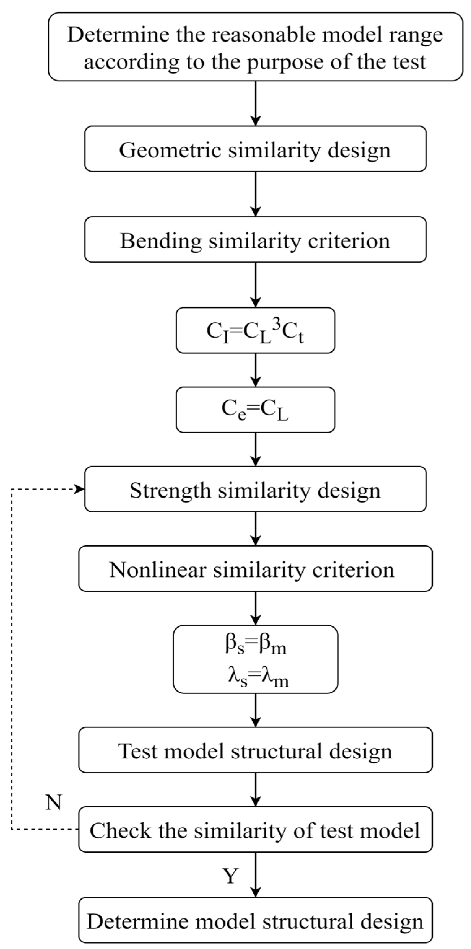
3. Test Model Design

Based on the distortion similarity theory and nonlinear similarity method under a pure bending moment, a similar test model of a nuclear-powered icebreaker reactor hull structure is designed to maintain the similar relationship between the test model and the actual ship during the collapse process.

3.1. Linear Similarity Principle

In thin-walled structures, the moment of inertia is a critical parameter representing the structural stiffness, whereas the height of the neutral axis signifies the structural strength. Traditional similarity theories often fail to account for the unique characteristics of thin-walled structures, particularly the significant differences between the linear dimensions and the thickness dimensions. Applying the distortion similarity theory to thin-walled structures enables a more accurate and reliable simulation of the structural responses. This methodology ensures that both the moment of inertia and the neutral axis height are scaled appropriately.
Based on the dimensional–directional analysis [21], the similarity principle of the moment of inertia is expressed as follows [22].
C I = I s / I m = C L 3 C t
C e = e s / e m = C L
C L = L s / L m
C t = t s / t m
where C represents the similarity coefficient between the actual ship and the test model; I represents the moment of inertia; e represents the neutral axis height; L represents the structure length; t represents the plate thickness; the subscript s means the actual ship; and m means the test model.

3.2. Nonlinear Similarity Method

It is noted that the stiffened plate is the basic unit of a hull structure, meaning that its collapse characteristics play an important role in the collapse characteristics of a hull girder.
Some researchers found that the collapse characteristics of stiffened plates under compression are greatly influenced by both the plate slenderness ratio (β) and the stiffener slenderness ratio (λ) [19].
A series of studies indicated that for stiffened plate structures of different scales, as long as the slenderness ratios of the plates and stiffeners are consistent, their collapse characteristics under a compression load will basically be the same. The formulas defining these parameters are as follows [19].
β = ( b / t ) σ Y / E
λ = ( a / r ) σ Y / E
r = I / A
where a represents the length of the plate; b represents the width of the plate; t represents the plate thickness; σY is the yield strength of the material; E is Young’s modulus; A is the cross-section area of the stiffener; I is the moment of inertia; and r represents the radius of gyration of the stiffener.
By modifying the size and spacing of the stiffeners in the similar model to ensure that the β and λ of the similar model are the same as those of the actual ship, the stiffened plate structure at the corresponding positions on both the actual ship and the test model can have the same nonlinear behavior. This ensures that the model accurately replicates the actual ship’s responses in nonlinear conditions. The nonlinear similarity method can be expressed as follows [20].
β s = β m
λ s = λ m

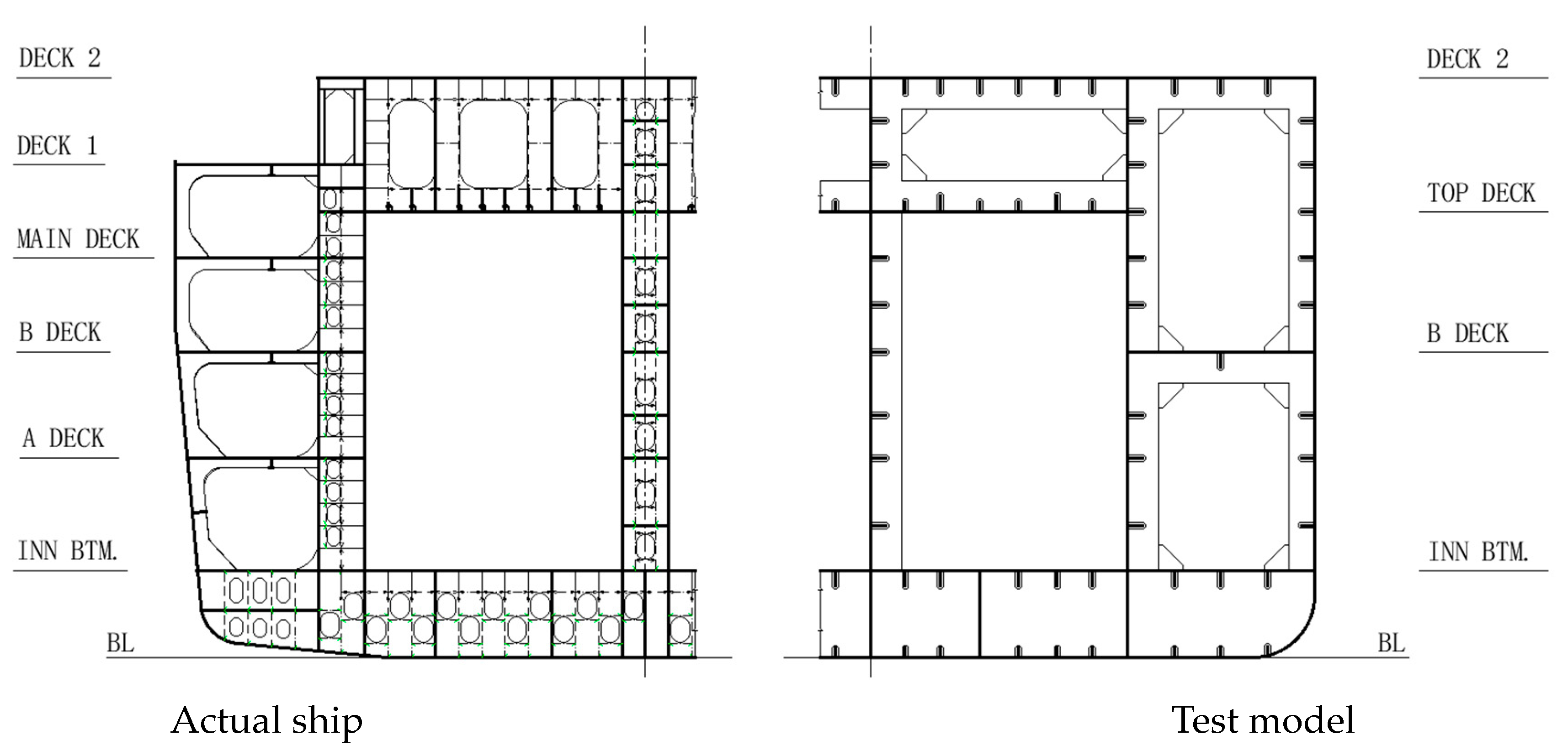
3.3. Design of Test Model

The test model is designed in accordance with distortion similarity principles, taking into account the similarity of the inertia moments and the neutral axis. The nonlinear similarity approach is utilized to determine the structural dimensions and arrangements for the model. If the discrepancy in the section properties between the model and the actual ship remains below 5%, the model is considered to meet the requirements. Conversely, adjustments to the stiffeners’ size and spacing are required to satisfy these criteria. The design process is depicted in Figure 1.
Upon meticulous consideration of factors such as the expenses, laboratory conditions, and model fabrication requirements, the geometric similarity factor CL is set as 10. According to the distortion similarity theory, the thickness is treated as a separate variable and the thickness similarity ratio Ct is set as 6.
The comparative analysis of the cross-sections between the actual ship and the test model is illustrated in Figure 2. In the test model, the three platforms near the neutral axis of the actual ship are consolidated into a single platform due to their minimal effect on the ultimate bending moment. The number of stiffeners may be appropriately reduced while maintaining the similarity cross-section properties. All the stiffeners in the test model are flat steel.
The cross-section properties between the actual ship and the test model are compared in Table 1, and the errors are all less than 5%. This shows that the typical characteristics between the actual ship and the test model can be kept consistent.

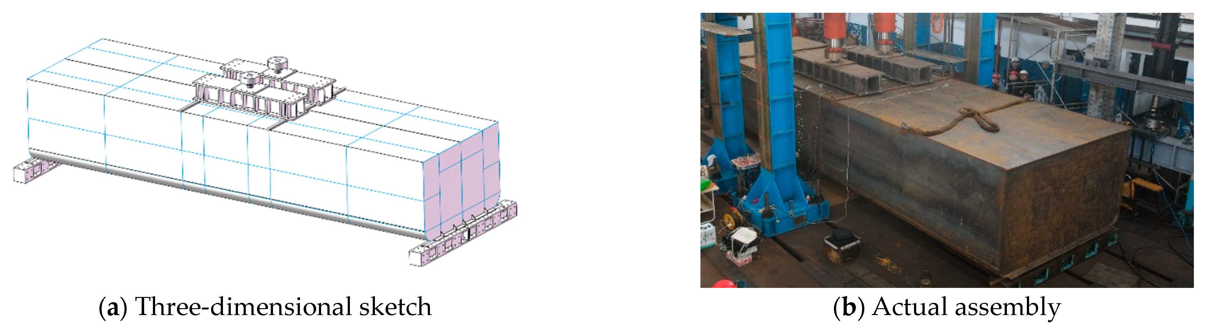
4. Collapse Model Test
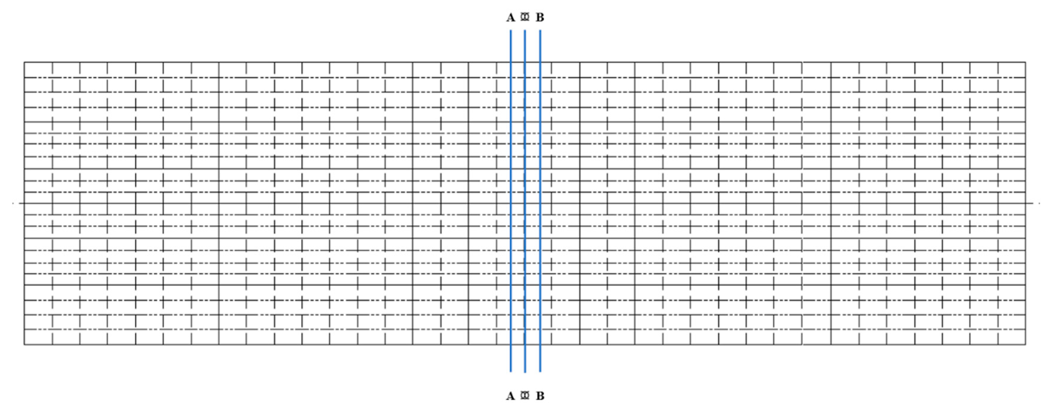
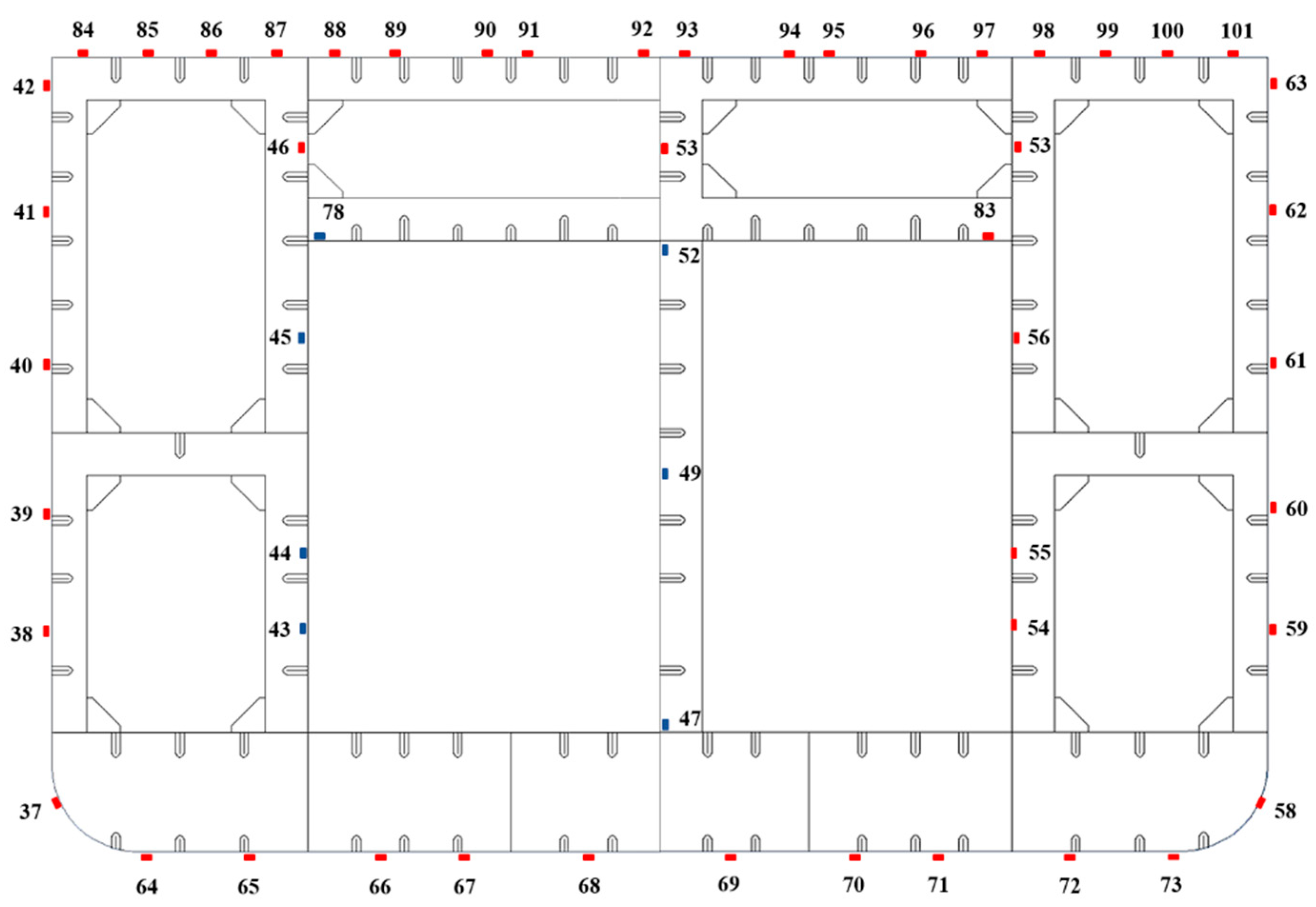
4.1. Test Plan

The test model sketch is shown in Figure 3. There are two oil jacks that act on the top of the test model, and two round bars at either end. The boundary conditions are detailed in Table 2. The load is applied on the top of the two transverse bulkheads in the middle of the test model by a distributive girder, thereby generating bending moments in conjunction with the constraint sections.
According to the finite element calculation result, there are a total of 160 strain gauges positioned at three critical cross-sections in the middle area to analyze the stress distribution situation and collapse behavior, as shown in Figure 4. The arrangement of the strain gauges for the midship section is shown in Figure 5. Additionally, dial indicators are installed at the base of the load transverse bulkhead to measure the displacement in the vertical direction.
To alleviate the effects of the welding residual stress, the test model is subjected to repeated preloading and unloading in the elastic phase. Once the system has been set up and debugged, the testing phase commences. During the loading process, the loads at both loading positions are progressively increased, with the structural responses being meticulously documented. As the load intensifies, the stress level of the structure also escalates until failure occurs. The maximum bending moment that the model can withstand is considered to be its ultimate strength.

4.2. Test Result

The bending moment at the midship section is ascertained by analyzing the applied load. Figure 6 illustrates the correlation between the bending moment and the displacement. The bending moment is taken as the vertical coordinate and the vertical displacement of the loading position is taken as the horizontal coordinate. The slope of the curve represents the bending stiffness of the test model.
During the initial phase of the model testing, the applied load is minimal, and the structure remains in the elastic phase. As the load progressively increases, the main deck plate in the central region of the test model buckles first, resulting in a decrease in stiffness. With the expansion of the buckling region, the bearing capacity of the structure gradually decreases. Ultimately, the test model collapses due to the overall buckling failure of the main deck plate and hull shell plate, as shown in Figure 7. The ultimate bending moment is Mm = 1.10 × 10¹⁰ N·mm.
Finite element analysis is performed on the test model to confirm the results of the model tests. The elements are finely sized to precisely replicate the buckling and collapse behaviors. The boundary condition and loading method are replicated to match those used in the model test. The stress distribution and collapse situation calculated are shown in Figure 8. Compared with the model test results, it can be seen that the test results and the finite element results have the same collapse situation and the collapse positions are also consistent, where the overall buckling failure occurs in the main deck plate and the hull shell plate. The results demonstrate a correspondence between the progressive collapse behavior observed in both the nonlinear finite element analysis and the model test.
The different moment–displacement curves are compared in Figure 9, which shows that the two lines coincide with each other in basically the linear stage. The error of the ultimate bending moment in the different results is 12.7%. As the influence of the welding residual stress produced during model manufacturing is not considered in the finite element analysis, the finite element result is greater than the test result.

5. Ultimate Bending Moment of the Actual Ship

5.1. Result Predicted from the Model Test

The test model is crafted based on the distortion similarity theory and the nonlinear similarity method so that the ultimate strength of the actual ship’s structure can be predicted through the similarity transformation relationship from the model test result.
The geometric ratio is set as CL = 10 and the thickness ratio is set as Ct = 6. The bending moment ratio CM can be calculated [22] as follows.
CM = CL2Ct
The ultimate bending moment of the actual ship Ms can be converted as follows.
Ms = CL2CtMm
where Mm is the ultimate bending moment of the test model.
According to the test result, Mm is 1.10 × 10¹⁰ N·mm, so that the ultimate bending moment of the actual ship can be predicted as Ms = 6.59 × 10¹² N·mm.

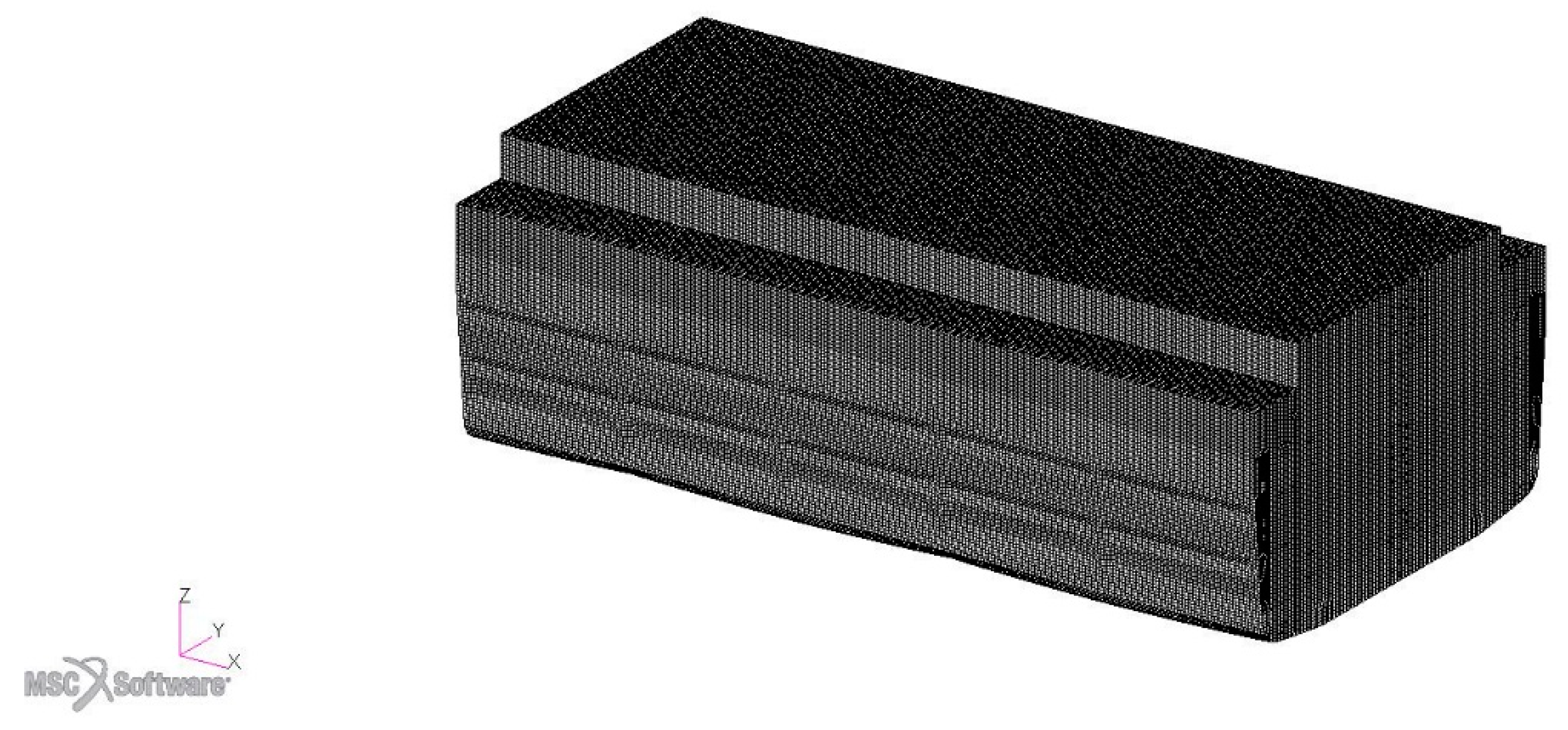
5.2. Result Calculated by Nonlinear Finite Element Analysis

Nonlinear finite element analysis is applied to the reactor hull structure of the actual ship, and the finite element model is shown in Figure 10. The model utilizes an elastic-perfectly plastic material assumption and includes 4-node doubly curved shell elements (S4R) and 3-node triangular shell elements (S3). The loading and boundary conditions are the same as those used in the model test.
The collapse situation of the actual reactor hull structure obtained by finite element analysis is shown in Figure 11. It shows that the buckling failure occurs on the deck plate and hull shell plate, which is the same as the result of the model test.
The moment–displacement relationship derived from the model test is translated to the actual ship using the similarity transformation and is compared with the finite element analysis results of the actual ship, as shown in Figure 12. It shows that the two curves are basically consistent with each other in the linear stage, and a difference gradually occurs after entering the nonlinear stage. As shown in Table 3, the actual ship’s ultimate bending moment predicted through the model test is 6.59 × 10¹² N·mm and the ultimate bending moment obtained by finite element analysis of the actual ship is 7.45 × 10¹² N·mm, where the error between them is 11.5%.
The structure of an actual reactor is significantly more complex than that of an ordinary ship. Consequently, the test model for the reactor is also more intricate compared to ship models studied in the past. This increased complexity may amplify the impact of the welding residual stress, which is not accounted for in the finite element analysis. As a result, the error is slightly larger than anticipated.

6. Conclusions

In this study, the finite element method and model test method are combined to investigate the collapse situation and ultimate strength of a ship reactor hull structure under a pure bending moment. The test model, designed using the distortion similarity theory and the nonlinear similarity method, is subsequently tested, and the results are compared with those from the finite element analysis. The findings indicate that the combined research method effectively captures the collapse situation and ultimate strength, with the model test results coinciding well with the finite element analysis. The main findings are as follows.
(1)
The distortion similarity theory and improved nonlinear similarity method are used to design the test model of the actual ship reactor hull structure. The cross-section properties of the test model and actual structure satisfy the similar ratio, which indicates that the test model is similar to the actual structure. The model design method adopted in this study is reasonable and reliable.
(2)
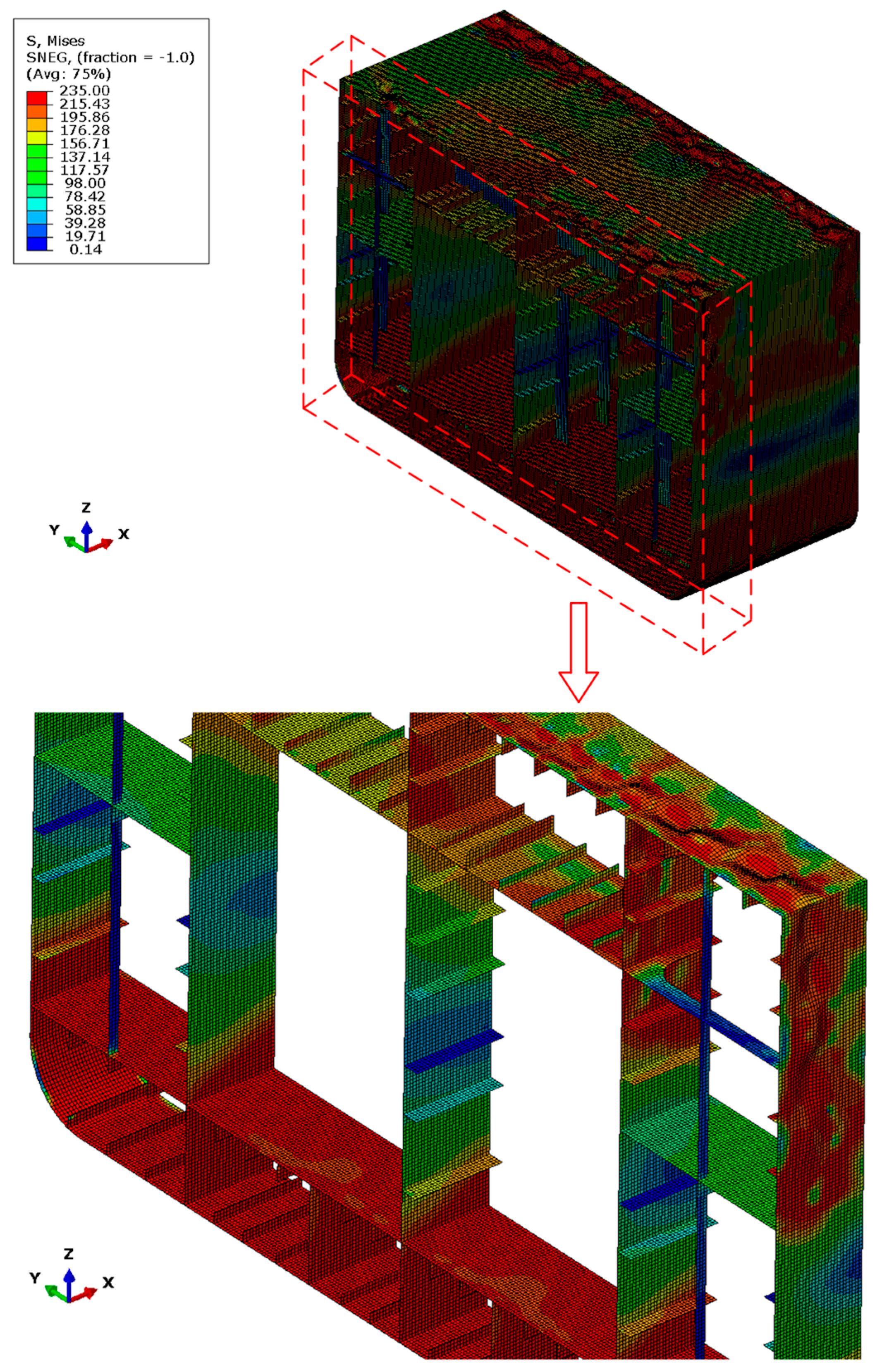
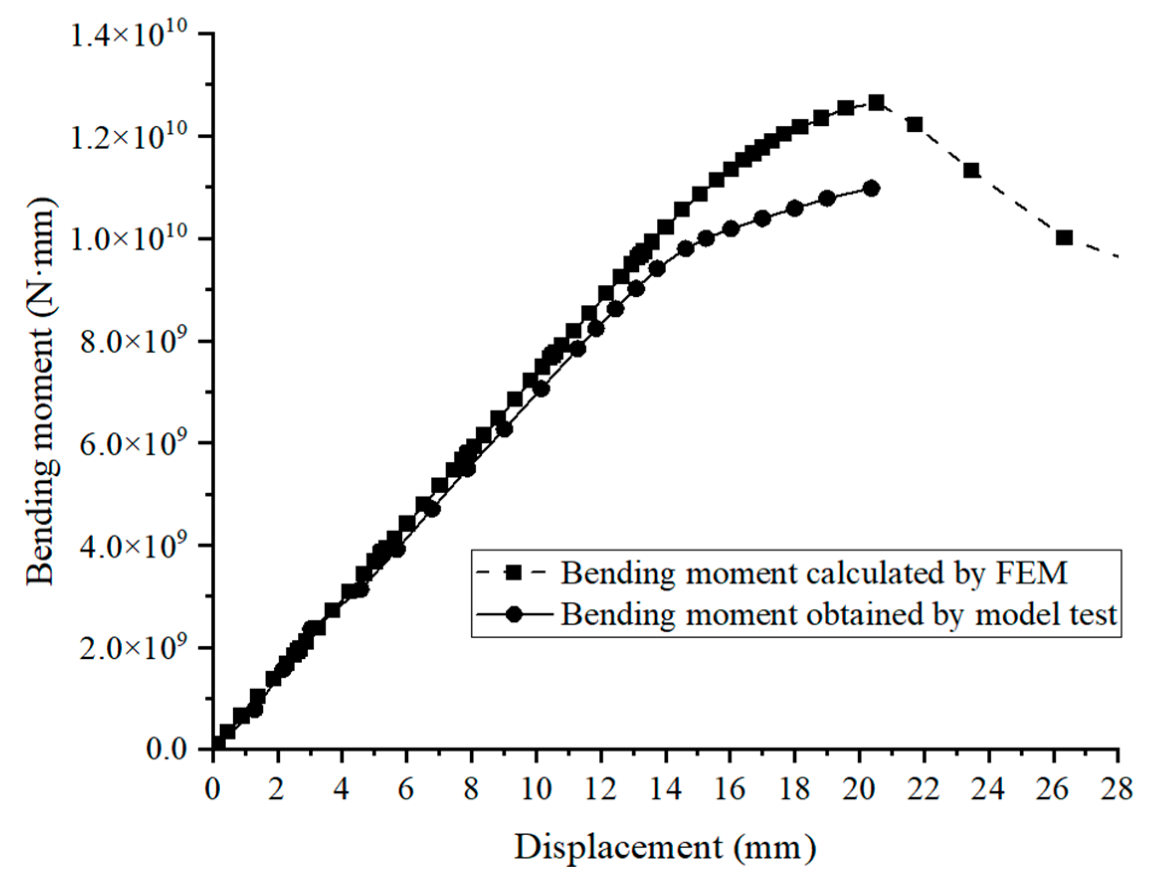
The collapse position, collapse situation and ultimate bending moment of the model test and test model finite element analysis are consistent. This verifies the accuracy of the finite element analysis results.
(3)
The collapse position and collapse situation of the model test and actual ship structure finite element analysis are consistent. The ultimate bending moment obtained by the model test is 1.10 × 10¹⁰ N·mm and transformed to the actual ship structure it is 6.59 × 10¹² N·mm through the similarity transformation relationship. The ultimate bending moment of the actual ship obtained by finite element analysis is 7.45 × 10¹² N·mm. The error between them is 11.5%. It is proved that the test model designed based on the distortion similarity theory and nonlinear similarity method can better predict the ultimate strength of the actual ship.

Author Contributions

Conceptualization, Y.L. and Z.P.; methodology, Z.P. and X.K.; software, R.C.; validation, Y.L., Z.P. and X.K.; formal analysis, R.C.; investigation, Y.L.; resources, Y.L.; data curation, Y.L. and L.C.; writing—original draft preparation, R.C.; writing—review and editing, Y.L., R.C., X.K. and Z.P.; visualization, visualization; supervision, Y.L. and L.C.; project administration, Y.L. and L.C.; funding acquisition, Y.L. and L.C. All authors have read and agreed to the published version of the manuscript.

Funding

This research received no external funding.

Institutional Review Board Statement

Not applicable.

Informed Consent Statement

Not applicable.

Data Availability Statement

Data is unavailable due to privacy.

Conflicts of Interest

Author Yi Lin was employed by the China National Nuclear Power Co., Ltd. The remaining authors declare that the research was conducted in the absence of any commercial or financial relationships that could be construed as a potential conflict of interest.

References

  1. Wang, D. Study on Structural Strength Evaluation Method of Containment Compartment of Nuclear Powered Icebreaker. Master’s Thesis, Dalian Maritime University, Dalian, China, 2022. (In Chinese). [Google Scholar]
  2. Wang, Q. Study on the Physical and Mechanical Engineering Parameters of Sea Ice during Melt Season for Arctic Passage. Ph.D. Thesis, Dalian University of Technology, Dalian, China, 2019. (In Chinese). [Google Scholar]
  3. Wu, S. Prospects for the Development of Nuclear Powered Icebreakers. Energy Environ. 2019, 4, 97–98. (In Chinese) [Google Scholar]
  4. Xu, J.; Qiu, J.; Song, F. Research on Conceptual Design of Nuclear-powered Icebreaker. Prog. Rep. China Nucl. Sci. Technol. 2009, 1, 72–76. (In Chinese) [Google Scholar]
  5. Cheng, R. Research on Nonlinear Similarity Method under Torsion Moment for Hull Structure. Master’s Thesis, Wuhan University of Technology, Wuhan, China, 2019. (In Chinese). [Google Scholar]
  6. Endo, H.; Tanaka, Y.; Aoki, G.; Inoue, H.; Yamamoto, Y. Longitudinal strength of the fore body of ships suffering from slamming. J. Soc. Nav. Archit. Jpn. 1988, 163, 322–333. [Google Scholar] [CrossRef]
  7. Yao, T.; Fujikubo, M.; Yanagihara, D.; Fujii, I.; Matsui, R.; Furui, N.; Kuwamura, Y. Buckling collapse strength of ship carrier under longitudinal bending (1st Report). J. Soc. Nav. Archit. Jpn. 2002, 191, 191–220. [Google Scholar]
  8. Yang, P. Research on Ultimate Strength of Ship Hulls and Residual Strength of Damaged Ships. Ph.D. Thesis, Wuhan University of Technology, Wuhan, China, 2005. (In Chinese). [Google Scholar]
  9. Gordo, J.; Soares, C. Experimental evaluation of the behavior of a mild steel box girder under bending moment. Ships Offshore Struct. 2008, 3, 347–358. [Google Scholar] [CrossRef]
  10. Gordo, J.; Soares, C. Tests on ultimate strength of hull box girders made of high tensile steel. Mar. Struct. 2009, 22, 770–790. [Google Scholar] [CrossRef]
  11. Shi, G.; Wang, D. Analysis of the Similar Model for Ultimate Strength Subjected to Combined Action of Bending and Torsion of a Container Ship. J. Shanghai Jiaotong Univ. 2010, 44, 782–786. (In Chinese) [Google Scholar]
  12. Xie, Z. Study on Design of Ultimate Strength Testing Cabin Model. Master’s Thesis, Shanghai Jiao Tong University, Shanghai, China, 2010. (In Chinese). [Google Scholar]
  13. Zhang, H. The Research of the Ultimate Strength Test Technology of Ship Structures. Master’s Thesis, Harbin Engineering University, Harbin, China, 2015. (In Chinese). [Google Scholar]
  14. Wang, Q.; Wang, D. Scaling characteristics of hull girder’s ultimate strength and failure behaviors: An empirically modified scaling criterion. Ocean. Eng. 2020, 212, 107595. [Google Scholar] [CrossRef]
  15. Zhang, S.; Khan, I. Buckling and ultimate capability of plates and stiffened panels in axial compression. Mar. Struct. 2009, 22, 791–808. [Google Scholar] [CrossRef]
  16. Zhou, F. Research on the Design Method of Hull Scaled Model in Ultimate Strength Test. Master’s Thesis, Wuhan University of Technology, Wuhan, China, 2014. (In Chinese). [Google Scholar]
  17. Pei, Z.; Wu, W. Ultimate strength research on river-sea-going ship with large hatch opening. In Proceedings of the International Offshore and Polar Engineering Conference, Busan, Republic of Korea, 15–20 June 2014; pp. 685–692. [Google Scholar]
  18. Garbatov, Y.; Saad-Eldeen, S.; Soares, C.G. Hull girder ultimate strength assessment based on experimental results and the dimensional theory. Eng. Struct. 2015, 100, 742–750. [Google Scholar] [CrossRef]
  19. Zhu, Z. Research on Nonlinear Similarity Criterion for Model Test of Ultimate Strength. Master’s Thesis, Wuhan University of Technology, Wuhan, China, 2017. (In Chinese). [Google Scholar]
  20. Cheng, R.; Pei, Z. Research on Nonlinear Similarity Method for Ultimate Strength Model Test. J. Wuhan Univ. Technol. Transp. Eng. 2020, 44, 195–200. (In Chinese) [Google Scholar]
  21. Araneda, J. Dimensional-directional analysis by a quaternionic representation of physical quantities. J. Frankl. Inst. 1996, 333, 113–126. [Google Scholar] [CrossRef]
  22. Pei, Z.; Yuan, Q.; Ao, L.; Wu, W. Research on the nonlinear similarity law on model collapse test of ship structures under combined bending and torsional moments. Ships Offshore Struct. 2023, 1–12. [Google Scholar] [CrossRef]
Figure 1. Test model design process [22].
Jmse 12 01184 g001
Figure 2. Comparison of the typical cross-section structure.
Jmse 12 01184 g002
Figure 3. Test model sketch.
Jmse 12 01184 g003
Figure 4. Locations of the strain gauges.
Jmse 12 01184 g004
Figure 5. Arrangement of the strain gauges for the midship section.
Jmse 12 01184 g005
Figure 6. Bending moment–displacement relationship.
Jmse 12 01184 g006
Figure 7. Collapse situation obtained by the collapse model test.
Jmse 12 01184 g007
Figure 8. Collapse situation calculated by FEM analysis.
Jmse 12 01184 g008
Figure 9. Comparison of the moment–displacement relationship.
Jmse 12 01184 g009
Figure 10. The finite element model of the actual reactor hull structure.
Jmse 12 01184 g010
Figure 11. Collapse situation of the actual ship.
Jmse 12 01184 g011
Figure 12. Comparison of the moment–displacement relationship.
Jmse 12 01184 g012
Table 1. Comparison of the cross-section properties.
ItemActual ShipSimilar
Transformation
Test ModelError
Height of neutral axis (mm)8788.0878.8875.50.3%
Section area (mm2)7.60 × 1061.27 × 1051.24 × 1052.2%
Moment of inertia (mm4)2.77 × 10144.62 × 10104.77 × 10103.2%
Table 2. Boundary conditions.
PositionUxUyUzθxθyθz
Bottom of the fore transverse bulkhead0000-0
Bottom of the end transverse bulkhead-000-0
Table 3. Comparison of the ultimate bending moment.
Ultimate StrengthPredicted ResultCalculated ResultError
Ultimate bending moment (N·mm)6.59 × 10127.45 × 101211.5%
Disclaimer/Publisher’s Note: The statements, opinions and data contained in all publications are solely those of the individual author(s) and contributor(s) and not of MDPI and/or the editor(s). MDPI and/or the editor(s) disclaim responsibility for any injury to people or property resulting from any ideas, methods, instructions or products referred to in the content.

