Article

Numerical Studies on the Hydrodynamic Patterns and Energy-Saving Advantages of Fish Swimming in Vortical Flows of an Upstream Cylinder

1
State Key Laboratory of Maritime Technology and Safety, Shanghai Ship and Shipping Research Institute Co., Ltd., Minsheng Rd. 600, Shanghai 200135, China
2
Institute of Naval Architecture and Ocean Engineering, Ningbo University, Ningbo 315211, China
*
Author to whom correspondence should be addressed.
J. Mar. Sci. Eng. 2024, 12(8), 1254; https://doi.org/10.3390/jmse12081254
Submission received: 29 May 2024 / Revised: 27 June 2024 / Accepted: 4 July 2024 / Published: 25 July 2024
(This article belongs to the Section Ocean Engineering)

Abstract

:
Fish in nature can extract the vortex energies from the environment to enhance their swimming performance. This paper numerically investigated the hydrodynamic characteristics and the energy-saving advantages of an undulating fish-like body behind the vortical flows generated by an upstream cylinder. The numerical model was based on a robust ghost cell immersed boundary method for the solution of incompressible flows around arbitrary complex flexible boundaries. We examined the dynamic characteristics, the swimming performance, and the wake structures of the downstream fish under different locations and diameters of the cylinder in a wide range of Strouhal numbers. It was found that the average drag coefficient was significantly reduced in the presence of the upstream cylinder, while the RMS (root mean square) lift coefficients were very close for different locations and diameters of the cylinder as well as in the fish-only case. Therefore, the downstream fish gain efficiency and thrust enhancement by capturing energies from the vortex flows, which are more significant for smaller Strouhal numbers (St). However, the swimming efficiency converges to near 0.12 at St = 1.2 for different locations and diameters of the upstream cylinder, just slightly higher than that of the fish-only case. The fish can experience the thrust in not only the von-Kármán vortex street, but also the reversed one. In addition, the fish can be situated in the extended shear layer region and the fully developed wake region dependent on the position and diameter of the upstream cylinder, leading to abundant wake modes such as the splitting, coalescing, and competing of vortices.

1. Introduction

It is known that fish can gain hydrodynamic advantages by undulating their fins or exploiting the energy from the fluid environment. The unique streamlined surface and propulsive mechanism of fish have provided inspiration for the design of many biomimetic robot fishes [1]. Underwater biomimetic robots have become progressively crucial in various underwater operations for their excellent swimming performance and good environmental adaptability such as marine energy exploitation and emergency rescue. To achieve a motion performance and efficiency similar to their biological counterparts in the natural environment, the key is to accurately understand and utilize the motion mechanism of the biological prototype.
Lighthill [2] conducted pioneer work on the theoretical analysis of the physical mechanism of fish swimming. He applied the slender body theory to the small-amplitude undulation of the fish and successfully revealed the basic mechanism of fish swimming. Wu [3] and Cheng et al. [4] proposed the two-dimensional (2D) and three-dimensional (3D) wave plate models. These theoretical models [4,5] enhance our understanding of the physical mechanism of the biological locomotion and flight, as presented in the review by Wu [6]. However, the theoretical analysis is usually limited to simple geometric configurations and simplified kinetic modes due to simplified mathematical models such as linear approximation and the assumption of inviscid flow. On the other hand, experimental observation by high-speed cameras and particle image velocimetry (PIV) is an indispensable means for investigating the swimming mechanism of aquatic animal. For example, Tu et al. [7] surveyed a live zebra fish in a tunnel by a tomographic PIV to explore the 3D flow characteristics. Piskur et al. [8,9] experimentally investigated the propulsion efficiency of a new-designed biomimetic unmanned underwater vehicle (BUUV). However, these experiments are cost-expensive and time-consuming. Furthermore, the 3D flow visualization is difficult to measure in detail.
To avoid the challenges of the experiments, computational fluid dynamics (CFD) techniques have attracted increasing attention. Many numerical models including the moving grid methods [10,11], immersed boundary methods (IBM) [12,13], and meshfree methods [14] have been proposed to reveal the force-generation mechanism and hydrodynamic characteristics of the swimming fish. Among them, the IBM manifests excellent advantages for moving rigid or flexible boundary flows because the computation is performed on the background Cartesian grid, and no grid reconstruction is needed [15,16]. By using the IBM, Wang et al. [17] simulated non-sinusoidal oscillation of a hydrofoil under different pitching frequencies by an immersed boundary method. It was found that the time-averaged input power coefficient was shown to increase with the pitching frequency and decrease with the maximum pitching amplitude. Ghommem et al. [18] simulated the hydrodynamic performance of a swimming fish with different fin configurations and revealed that the caudal fin with a controlled flapping frequency could enhance the thrust generation.
It is known that fish can exploit the energy from the shedding vortices generated by the undulating of itself to swim forward. Moreover, fish can obtain hydrodynamic advantages by extracting the vortex energy from the adjacent fish or those generated from the obstacles. Fish schools are widespread in nature [19], which can be explained from hydrodynamic aspects. To investigate the hydrodynamic advantages of a fish school, Deng et al. [20] simulated the in-phase undulation of two tandem foils undergoing fishlike swimming by an IBM. It was found that the fish encountered thrust boost or deduction strongly dependent on the Strouhal number. Khalid et al. [21] numerically studied the asynchronous undulation of two tandem fish and showed that the upstream fish gained much drag deduction, while the force coefficients of the downstream fish were strongly dependent on the phase speed. Dai et al. [22] solved the self-propelled movement of two, three, and four swimming fishes in nine configurations. It was observed that multiple stable configurations were formed by hydrodynamic interactions. Kurt et al. [23] studied the self-propelled swimming of two pitching hydrofoils through new experiments. They found that the thrust and the efficiency of the side-by-side hydrofoils increased by 100% and 40%, respectively. For other related studies, please refer to [24,25].
Besides obtaining energy from the adjacent bodies, fish can also transform motion strategies to exploit the vortical flows caused by obstacles. It has often been observed by anglers that trout like to hide behind rocks to “rest”. To explore the underlying mechanism, Liao [26] and Liao et al. [27] experimentally studied the swimming behaviors of the trout in Kármán vortical flows behind a cylinder. They found that the muscle activity of the trout in cylindrical wake flows can apparently be lower than that in free-stream flows. The trout can gain hydrodynamic advantage from the vortex energy generated by the upstream cylinder with very little energy consumption. In addition, Beal et al. [28] found that the dead fish could generate forward propulsive motion in a vortical flow behind a cylinder, though there was no forward flow velocity. There have also been numerical investigations [29,30,31] involving the undulation of flexible boundaries in the vortex flows generated by the upstream cylinder. For example, Hu et al. [32] studied the fluid induced oscillation of an elastic plate behind a rotating cylinder. The mode transition features and the formation mechanism of the flapping filament were analyzed. Sahu [29] simulated the flow induced oscillation of an elastic plate attached on a cylinder. The effects of the elastic plate on the motion and dynamic characteristics of the upstream cylinder were also examined.
In the afore-mentioned experimental and numerical studies for flexible bodies behind the wake of a cylinder [27,28,29,30,32], the flexible body undulates with the oncoming vortices passively. Moreover, the focus was placed on the flapping characteristics of the flexible body [32] or the dynamic response of the upstream cylinder [29]. However, the influences of the upstream cylinder on the dynamic performance of the downstream flexible body have rarely been investigated. Furthermore, few studies have been devoted to the energy exploiting of an actively undulating flexible body in the vortex flows generated by an upstream cylinder. To gain a deeper understanding of the vortex energy exploiting, this paper numerically investigated the hydrodynamic characteristics and energy-saving advantages of an actively oscillating fish in the vortex flows of a cylinder. The present numerical model was based on a robust ghost cell immersed boundary method (GCIBM) with GPU acceleration to simulate the incompressible flows around rigid and flexible boundaries. This method can treat multiple complex boundaries well without adding the grid complexity, compared with the moving grid method. Parametrical studies were performed on the gap spacing between the leading edge of the fish and the cylindrical center, the cylindrical diameter, and the Strouhal number. The dynamic characteristics, the propulsive efficiencies, and the wake structures of the fish in the vortical flow were quantitatively evaluated in comparison with those in free flow. This study is expected to provide new insights into fish swimming behind rocks in nature. Furthermore, it is helpful for the design of UUVs (unmanned underwater vehicles) and their carriers in engineering.

2. Physical and Numerical Models

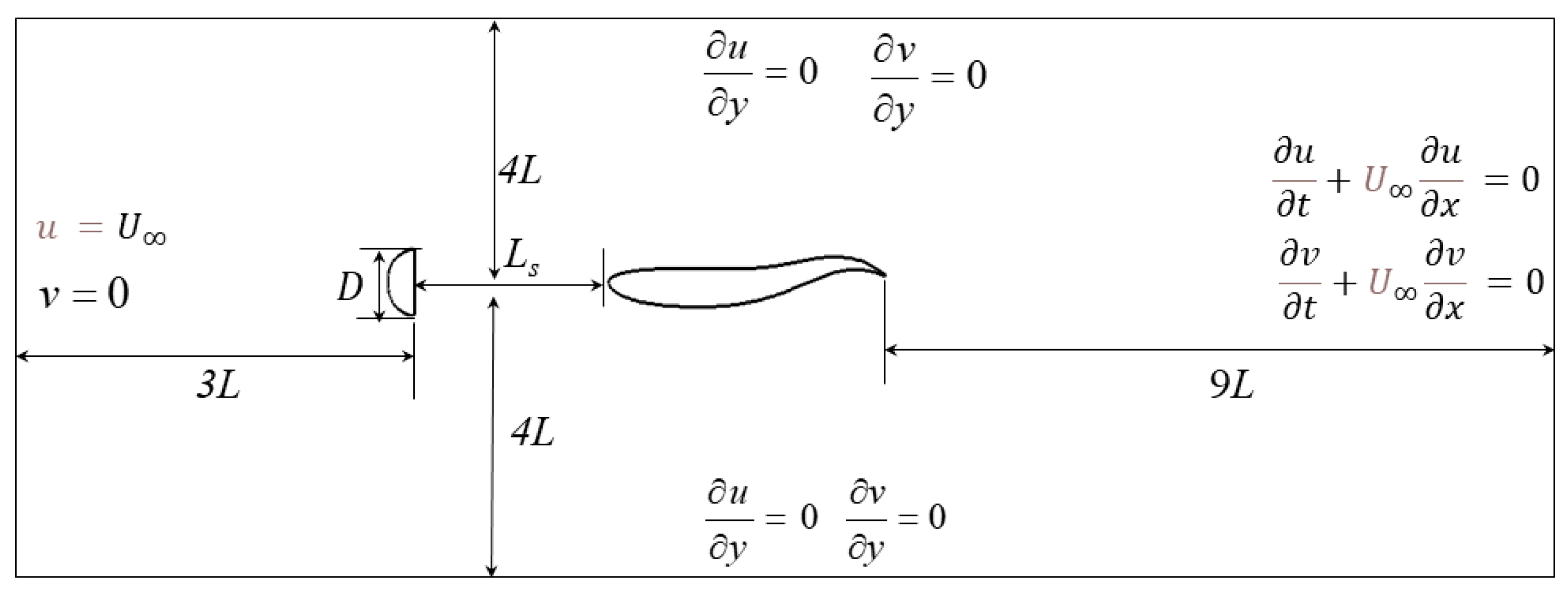
2.1. Problem Description

This study investigated the vortex shedding flows around an undulating fish with prescribed kinematics. The vortex shedding flows were generated by a D-section cylinder to further enhance the generation of vortex shedding. The fish surfaces were described by the airfoil profile of NACA0012. The geometrical model of the fish swimming and the boundary conditions are presented in Figure 1. The fish was located downstream of the cylinder with a gap distance of Ls and positioned 4 L away from the two side walls. Its distance to the outlet boundary was set as 9 L, where L is the length of the fish. In addition, the distance of the D-section cylinder to the inlet was 3 L. The freestream flow was imposed on the inlet boundary with the uniform flow of U. The two side walls were treated with the slip boundary conditions. A fully-developed free stream was adopted on the outlet boundary. Regarding the pressure, the Dirichlet boundary condition was employed on the outlet with a reference pressure of zero, and the Neumann condition was enforced on the other walls.
The fish undulates transversely in a sinusoidal function, which is expressed as:
y x , t = A x sin ( k x c t )         0 x L
where x is the local coordinate along the central axis of the fish; y is the transverse coordinates with respect to the midline of the fish; A(x) is the amplitude envelope along the horizontal direction; k is the wave number with the definition of k = 2π/λ; λ represents the wave length; t means the time; c defines the phase speed with c = 2πf; f is the undulation frequency.
To simulate the undulating of the fish, λ/L and A(x) are the important shape parameters. The fish length was set to L = 1 m, and the wave length was λ = L. Therefore, the wave number was obtained as k = 2π. The amplitude envelope is described as follows:
A x = C 0 + C 1 x + C 2 x 2
where C0, C1, and C2 are the constant coefficients. Following the work of Khalid et al. [21], C0, C1, and C2 were determined as A(0) = 0.02, A(0.2) = 0.01, and A(1) = 0.10. These were obtained as C0 = 0.02, C1 = 0.0825, C2 = 0.1625, respectively.

2.2. Numerical Model

In the present study, the flows around arbitrary moving boundaries were governed by incompressible Navier–Stokes (N–S) equations, which were solved by the GPU accelerated GCIBM [33]. The 2D governing equations in the vector form are given as:
u = 0       in   Ω
u t + u u = 1 ρ p + 1 ρ μ u + u T   in   Ω
u | Γ = V i     and   p n i | Γ = n i d V i d t
where u represents the velocity in the Cartesian grid system; p denotes the pressure; ρ is the density; μ is the dynamic viscosity coefficient; V i denotes the velocity of the undulating fish at the Lagrangian point of i ; n i describes the normal vector of the immersed boundary at the Lagrangian point of i ; Ω and Γ denote the computational domain and the immersed boundary, respectively.
An explicit finite difference method with a GPU acceleration was adopted to resolve the N–S Equations (3) and (4) on a staggered Cartesian grid. Equations (3) and (4) are integrated in time by a total variation diminishing second-order Runge–Kutta (TVD-RK3) scheme combined with the fractional step method. The convective term was approximated by a TVD higher-order monotonic upstream-centered scheme for conservation laws (TVD-MUSCL). The viscous term was treated by a central difference scheme. The intermediate velocity was predicted by explicitly solving the momentum equation. A pressure Poisson equation was solved to obtain the pressure by a preconditioned BICGSTAB (biconjugate gradient stabilized) algorithm. The present GCIBM was employed to meet the no-slip boundary conditions on the fish surface in Equation (5). Implementation details of the numerical model are presented in Xin et al. [34] and Shi et al. [33].
To clarify the flow characteristics, the Reynolds number (Re = LρU/μ) and the Strouhal number (St = 2Amaxf/U) are two critical flow parameters, where Amax is the maximum undulating amplitude of the fish. According to Equation (2), we can obtain Amax = 0.1 m. The instantaneous horizontal (Fx) and transverse (Fy) forces were approximated by integrating the pressure and viscous stress on the fish surfaces using a bilinear interpolation scheme. The instantaneous drag (CD) and lift (CL) coefficients are defined as:
C D = 2 F x ρ L U o 2 ,   C L = 2 F y ρ L U o 2
Note that the negative drag is termed as the thrust. The time-averaged drag ( C D a v g ) and root mean square (RMS) lift ( C L r m s ) coefficients are computed as:
C D a v g = 1 n T 0 n T C D d t ,   C L r m s = 1 n T 0 n T C L 2 d t
where T is the beating period of the fish with T = 2π/f and n is the number of the oscillation cycle. The horizontal force in Equation (6) is the net force that propels or hinders the fish forward. It manifests as the thrust type when the net force becomes negative, which means that the thrust force exceeds the drag force. Similarly, it shows as the drag force when the net force is positive, which means that the drag force outweighs the thrust force. The direction of the net force characterizes the relative proportion between the drag force and the thrust force. However, the horizontal force in Equation (6) is termed as the drag or thrust force for simplicity in the following description.
The swimming power (Ps) making the fish undulate in the transverse direction is expressed as:
P s = ( f y p + f y f ) V d s
where f y p and f y f are the pressure and the friction force at the Lagrangian points, respectively; V is the transverse velocity at the Lagrangian points; ds represents the element area of the fish surface. The propulsion power driving the fish moving forward is defined as P D = F ¯ D U . The total power can be obtained by PT = Ps + PD, where the thrust performs the positive work, and the transverse force performs the negative work. Therefore, the propulsive efficiency can be defined as:
η = P D P T
It should be noted that the propulsive efficiency in Equation (9) only holds in the condition of constant-speed swimming. Otherwise, the fish will be in an acceleration or deceleration state when the net force is not zero. In this study, the fish is held in place, and the propulsion velocity of the fish is equal to the free-stream velocity. The net force on the fish surface is usually not zero. As a consequence, the efficiency equation in Equation (9) cannot represent the ratio between the propulsion and the total powers. However, the introduction of propulsive efficiency in Equation (9) is still meaningful, since it can reflect the variation trend of the true efficiency with the flow parameters.

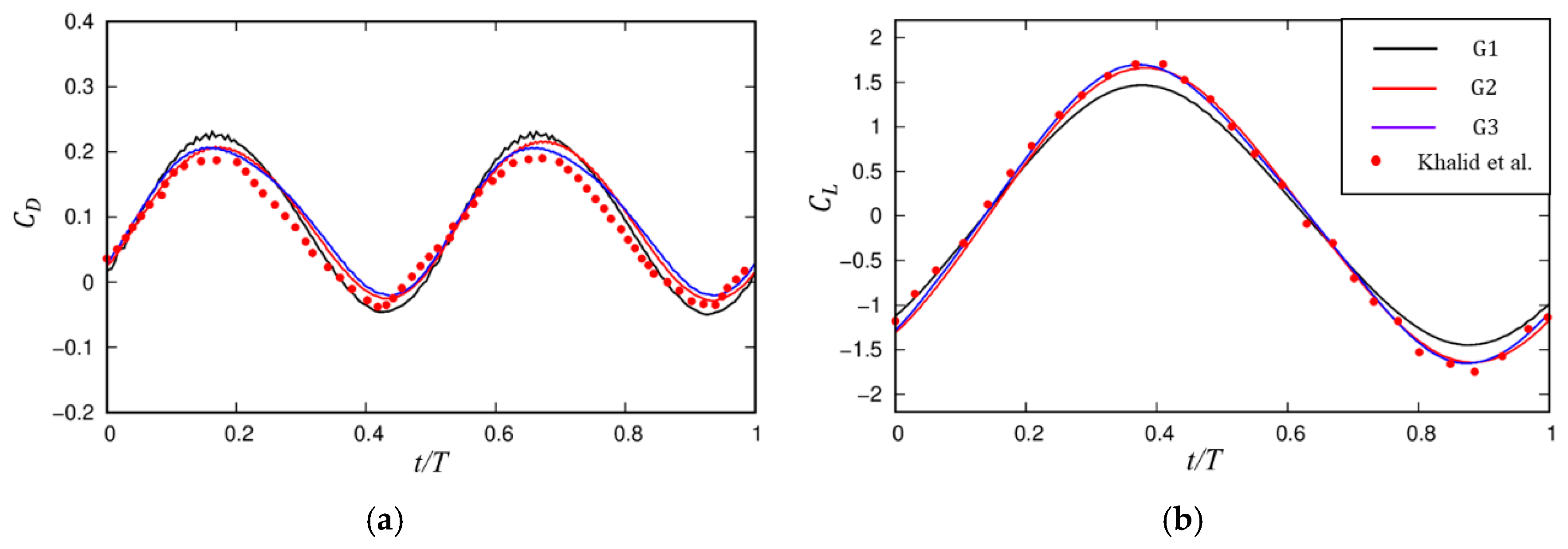
2.3. Numerical Validation

The accuracy and capability of the current method were comprehensively demonstrated in our prior research [33,34]. To further verify the current model for flexible boundary flows, uniform flows around an undulating fish were simulated. The geometrical profile and the kinematic form of the fish are given in Section 2.1. The Reynolds number was set to Re = 500 in this study. The simulation was performed on a domain of [−4 L, 12 L] × [−4 L, 4 L]. Additionally, a non-uniform grid was applied on the refined area of [−0.2 L, 1.3 L] × [−0.2 L, 0.2 L]. The boundary conditions are explained in Section 2.1. Three grid systems were tested for the case of St = 0.4 to examine the grid convergence, as shown in Table 1. The uniform flow velocity was set as U = 1 m/s. The Strouhal number (St) was obtained by varying the oscillating frequency fe, which was fe = 2 HZ in this case.
As seen in Table 1, the force coefficients tended to converge toward those on the finest grid as the grid became refined, where Δ x min and Δ y min are minimum grid size in the x- and y-directions, respectively. The maximum lift coefficients C L , max on two finer grids were identical. The average drag coefficients C D , a v g were very close, with a relative error of 1.2%. The results indicate that the grid convergence had been reached. Figure 2 plots the lift and drag coefficients against time for three grid systems at St = 0.4. The current numerical results are in satisfactory agreement with those reported by Khalid et al. [21]. The force coefficients on two finer grids were nearly the same as those of Khalid et al. [21]. Specifically, the C L , max was slightly underpredicted by about 1%, and the maximum drag coefficient was overestimated close to 3%, compared with the results by Khalid et al.

3. Numerical Results and Discussion

This section discusses the dynamics and wake features of an undulating fish in the downstream of a D-shape cylinder, called the cylinder for simplicity. The influences of the location and diameter of the upstream cylinder were examined in a wide range of Strouhal numbers. The parameters under different test conditions are listed in Table 2. The Reynolds number Re was 500, in consistent with that in Section 2.3. Additionally, the Strouhal number (St) was determined by setting the oscillating frequency fe, which was between 0 and 6 HZ in this study. The fish-only case in Section 2.3 was added for comparison, which is denoted by case #1. This was expected to reveal the hydrodynamic mechanism of the fish taking advantage of the Kármán vortex streets. The physical model and the related parameter settings are given in Section 2.1.

3.1. Effects of the Location of the Cylinder

The effects of the location of the upstream cylinder on the dynamics and wake characteristics of the downstream fish were investigated first. The settings were prescribed as cases #1–#5 in Table 2. The diameter was set as D/L = 0.2. The wave number of the fish was fixed as k = 2π. The gap spacing from the cylinder to the fish varied from Ls/L = 0.3 to 4. Based on the grid convergence tests in Section 2.3, a non-uniform Cartesian grid was employed with a moderate grid of Δ x min = 0.004 L and Δ y min = 0.00267 L on the local area.

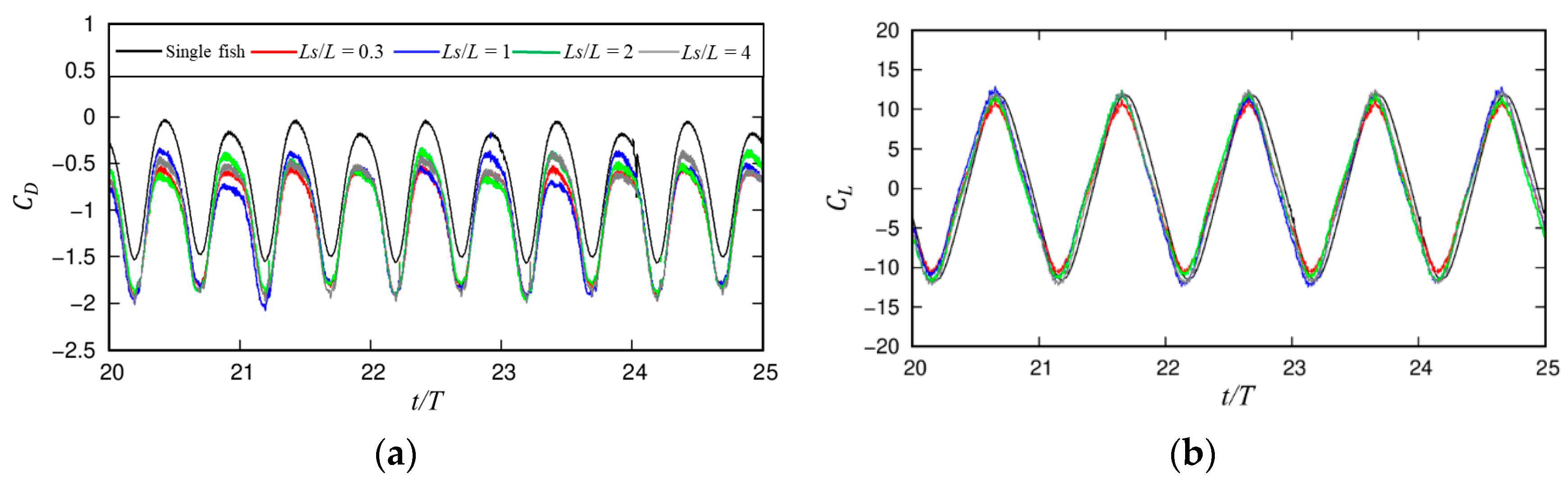
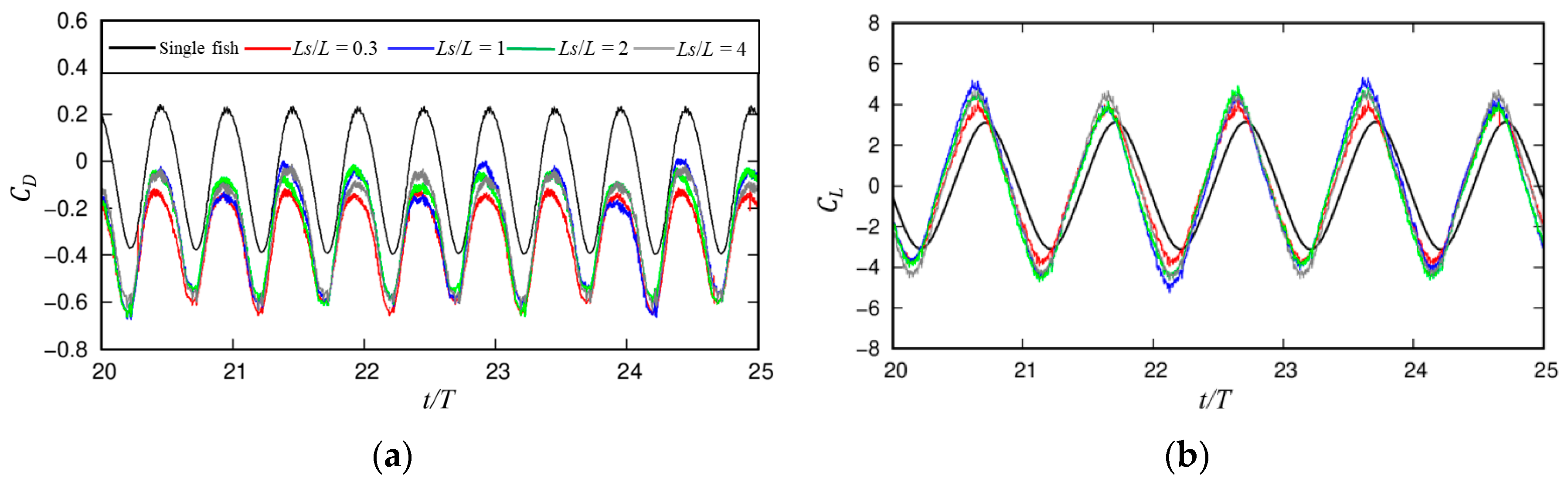
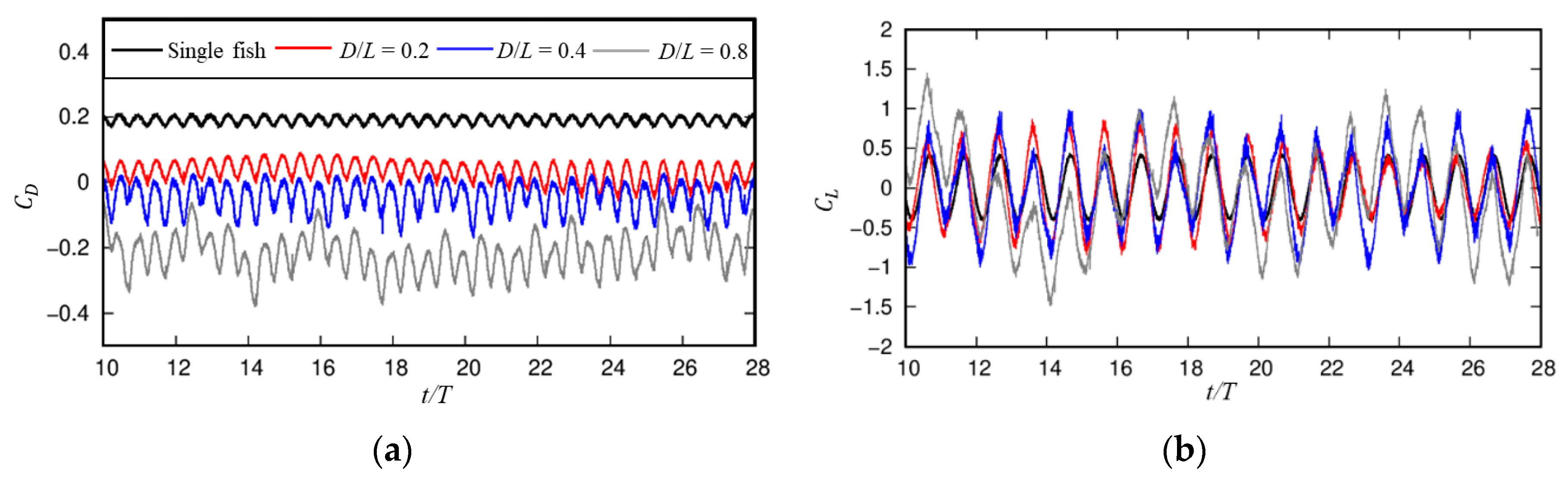
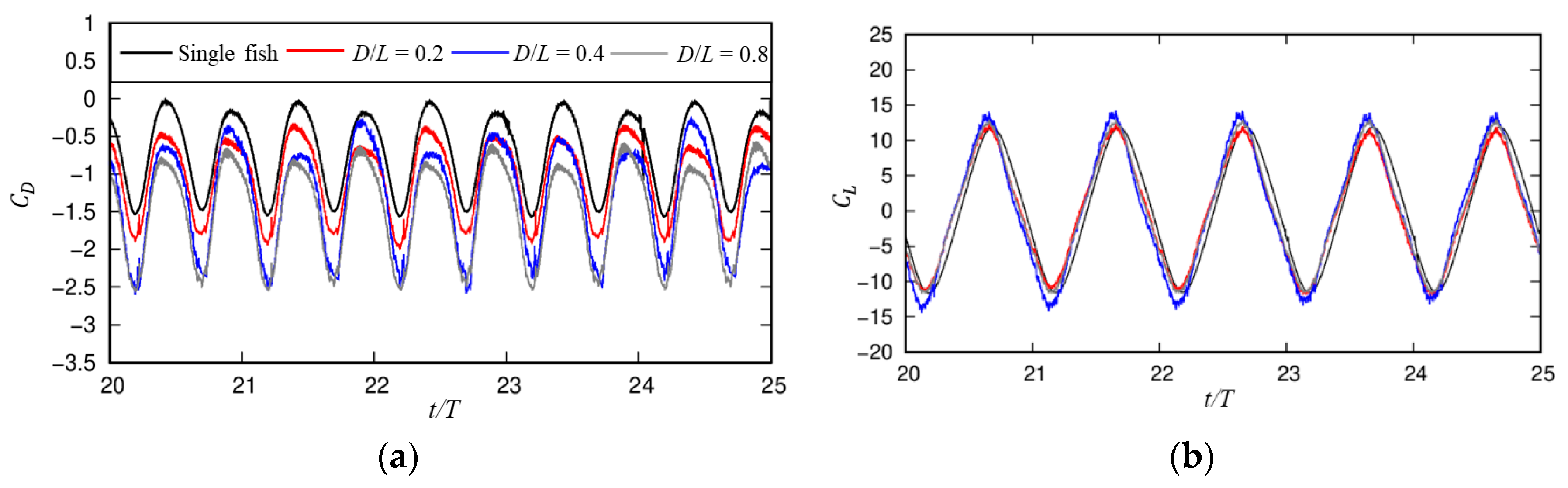
3.1.1. Dynamic Characteristics

The force patterns at several typical Strouhal numbers were first examined. Figure 3, Figure 4 and Figure 5 show the force coefficients against time for different gap distances at St = 0.2, 0.6, and 1, respectively. Case #1 for the undulating fish without the upstream cylinder was included, as shown by the black line. The force patterns on the fish behind the cylinder were distinct for different gap distances and Strouhal numbers.
In the case of St = 0.2, the sinusoidal oscillations of both the drag (CD) and lift (CL) coefficients were observed for Ls/L = 0.3, similar to those in the fish-only case, as seen in Figure 4. However, the fish encountered negative drag, namely the thrust, during the entire swimming period. The reason for this is that the free-stream flow is blocked by the cylinder, and in turn, the fish suppresses the generation of the vortex streets by the upstream cylinder. For Ls/L = 1, the sinusoidal variation patterns of the force coefficients observed in the fish-only case were disturbed by the vortex shedding flow, which can be explained by the Fourier spectra analysis. Both the drag and lift coefficients exhibited an obvious beating pattern. In every beating cycle of close to 10 s, the drag coefficient showed sinusoidal oscillation characteristics including a small sinusoidal oscillation with a short period of 1 s. The fish can experience the positive or negative drag in the oscillation period. The lift coefficient oscillated around the net force of zero with the varied amplitudes. For a wider spacing of Ls/L = 2 or 4, the beating pattern was weakened, and the force coefficients showed a slightly irregular oscillation pattern. Moreover, the drag coefficient was reduced and was turned into the thrust during the entire swimming period.
Figure 5. Force coefficients against time for different gap distances at St = 1: (a) CD; (b) CL.
Jmse 12 01254 g005
At St = 0.6 and 1, the force coefficients showed regular oscillation for different gap spacings, similar to the fish-only case. Specifically, the drag coefficients on the fish under four gap spacings demonstrated a slightly flat crest and a sharp trough, instead of the sinusoidal variation, which were very close and much smaller than those in the fish-only case. Regarding the lift coefficients, their amplitudes for four gap distances were slightly larger than those in the fish-only case at St = 0.6. The lift coefficients nearly coincided with those in the fish-only case at St = 1. In addition, the force patterns for Ls/L = 2 and 4 were nearly indistinguishable at various Strouhal numbers.
Figure 6, Figure 7 and Figure 8 present the amplitude spectra of the lift coefficient by fast Fourier transform (FFT) at three Strouhal numbers for Ls/L = 0.3, 1, and 2. The CL-spectrum showed single peak features for Ls/L = 0.3, where the peak occurred at the undulation frequency (fe) of the fish. At such a narrow distance, the alternative shedding vortices by the cylinder are interrupted by the adjacent fish before it can be fully developed. There were two peak frequencies of the CL for Ls/L = 1 and = 2 at various Strouhal numbers. The primary peak occurred at the undulating frequency (fe) of the fish, which was 1 at St = 0.2, 3 at St = 0.6, and 5 at St = 1. The secondary frequency fc corresponded to the vortex shedding frequency of the cylinder. At St = 0.2, the primary frequency fe was close to the secondary frequency fc for Ls/L = 1. The two peaks of the CL-spectra at fe and fc were comparable, leading to the strong nonlinear interaction, which explains the beating patterns of the force coefficients for Ls/L = 1 in Figure 4. Moreover, the undulating frequency (fe) of the fish was nearly equal to the secondary frequency fc for Ls/L = 2, leading to the resonance response.
At a higher Strouhal number of St = 0.6 and 1, the single peak pattern of the CL-spectrum with a higher amplitude was still presented for Ls/L = 0.3. This indicates that the alternative vortex shedding of the cylinder was not formed. On the other hand, the primary peak of the CL grew dramatically for Ls/L = 1 and 2, while the secondary peak at fc did not change much. For example, the primary peak was around seven times larger than the secondary peak at St = 0.6, and 16 times at St = 1 for Ls/L = 1. The impinging of the cylinder exerted a minor effect on the downstream fish. The prominent reduction in the drag coefficients in Figure 3, Figure 4 and Figure 5 can mainly be attributed to a momentum deficit region around the fish. The peak of CL-spectra at fc was reduced significantly when the gap distance increased from Ls/L = 1 to Ls/L = 2 because the strength of the impinging on the fish is weakened at a wide spacing. However, the variation in the secondary peak induced by the gap distance had negligible effects on the force coefficients of the downstream fish, since the secondary peak at fc was much smaller than the primary peak at fe.
Figure 9 plots the C D a v g and C L r m s as a function of the Strouhal number under different gap spacings. Generally, the C D a v g decreased and the C L r m s grew super-linearly with the increase in the St for different gap distances. The mean drag coefficients for different gap distances nearly coincided, while they were significantly smaller than those in the fish-only case. The disparity was more obvious for a larger St. In contrast, the RMS lift coefficients at different gap spacings as well as the fish-only case were similar at various Strouhal numbers. It was revealed that the downstream fish could swim forward with a small undulating frequency or accelerate forward at a fast speed in comparison with the fish-only case when the assumed numerical tether was removed. There was no significant increase in the lift force, which contributed to the negative work. As a result, the fish behind an obstacle can maintain steady swimming with less muscle activities, which means a higher swimming efficiency. Note that the C D a v g on the downstream fish was close to zero at St = 0, which means that the thrust cancels the drag. Therefore, the stationary fish behind an obstacle can hold in place in the incoming flow and even drift upstream for Ls/L = 0.3.
Furthermore, the swimming efficiency η of the fish against the St for various gap distances was studied, as shown in Figure 10. The swimming efficiency η at some St is not shown, since drag was encountered, and thus, the fish could not swim forward. For Ls/L = 0.3, the fish could achieve steady swimming at various Strouhal numbers and even at a stationary state. The fish gained a swimming efficiency of η = 1 at St = 0, since the stationary fish experienced no energy loss. However, the swimming efficiency was reduced dramatically to close to 0.12 as the St rose from 0 to 1.2. In addition, a critical Strouhal number of St*, if the mean net force is zero, can be found for other gap distances. In the present study, the St* was lower than 0.4 for Ls/L = 1, 2 and 4, and close to 0.6 in the fish-only case. A small St* means that the fish can consume less muscle activities to obtain the same cruising speed of swimming. Note that this critical Strouhal number is usually higher than that naturally selected by swimming fish, which is between 0.2 and 0.4 [5,35,36,37]. The underlying cause can be attributed to the distinct Reynolds numbers encountered. Aquatic animals usually swim in a turbulent flow environment. For mammals, sharks, and scombrids, the Reynolds numbers they experience are in a magnitude of 105 [5], far larger than that adopted in this study. The viscous force is non-negligible at a low Reynolds number, and thus the fish need to undulate faster to overcome the large viscous drag. The critical Strouhal number would approach that of natural fish as the Reynolds number grows, as reported by Borazjani and Sotiropoulos [38].
The η of the downstream fish was boosted in comparison with the fish-only case at various Strouhal numbers. This observation is consistent with the conclusion in Figure 9 in which the thrust obtained remarkable enhancement without the significant increase in the lift in the presence of the cylinder. The enhancement of the η was more evident at a small St. As the St rose to over 0.8, the swimming efficiency η was nearly independent of the Ls. The η on the downstream fish converged to about 0.12, slightly higher than that in the fish-only case. This mechanism of efficiency enhancement can potentially be used by underwater robots to save on the cost of locomotion for the maintenance of subsea pipelines. Additionally, UUVs can benefit from the reduced energy consumption by adapting to the wake behind its carrier.

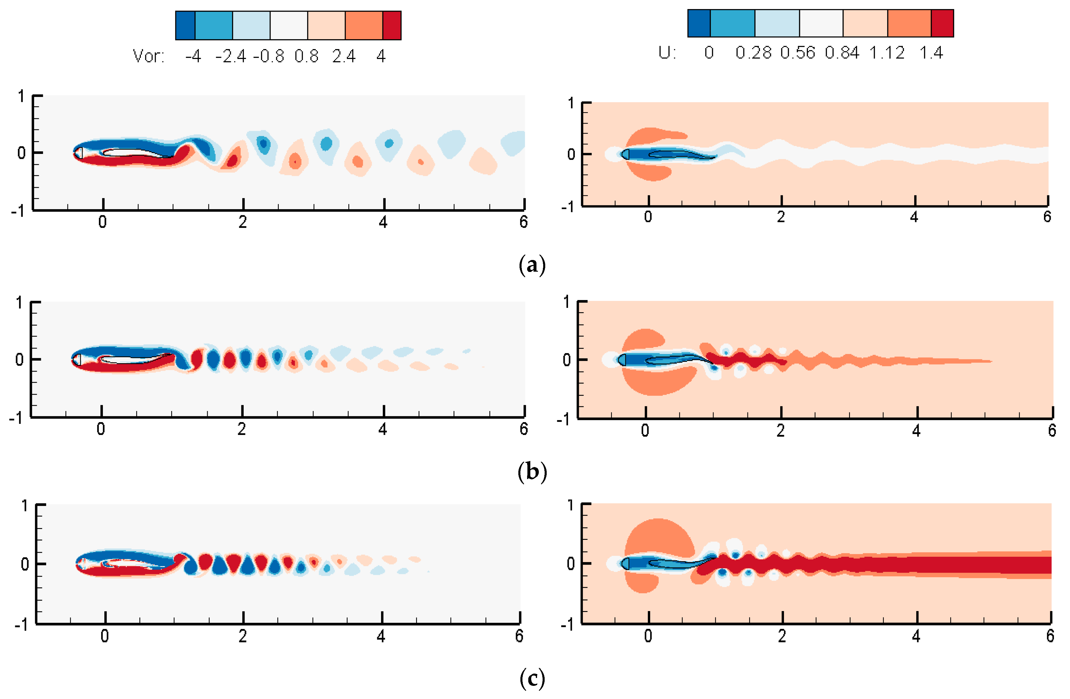
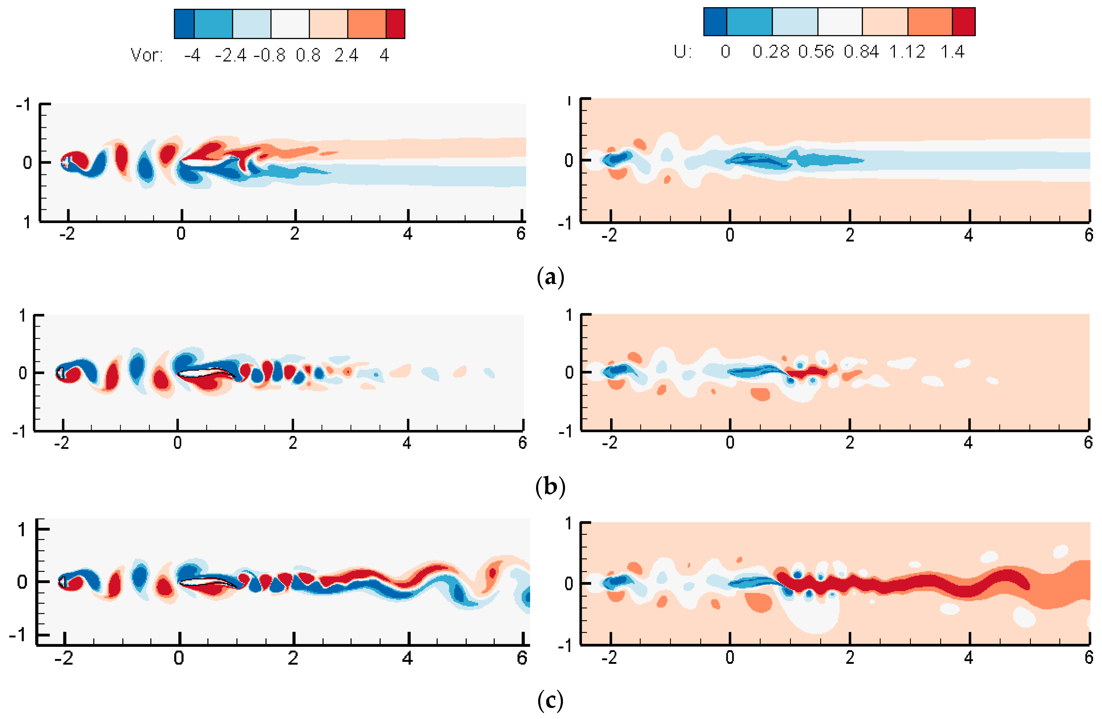
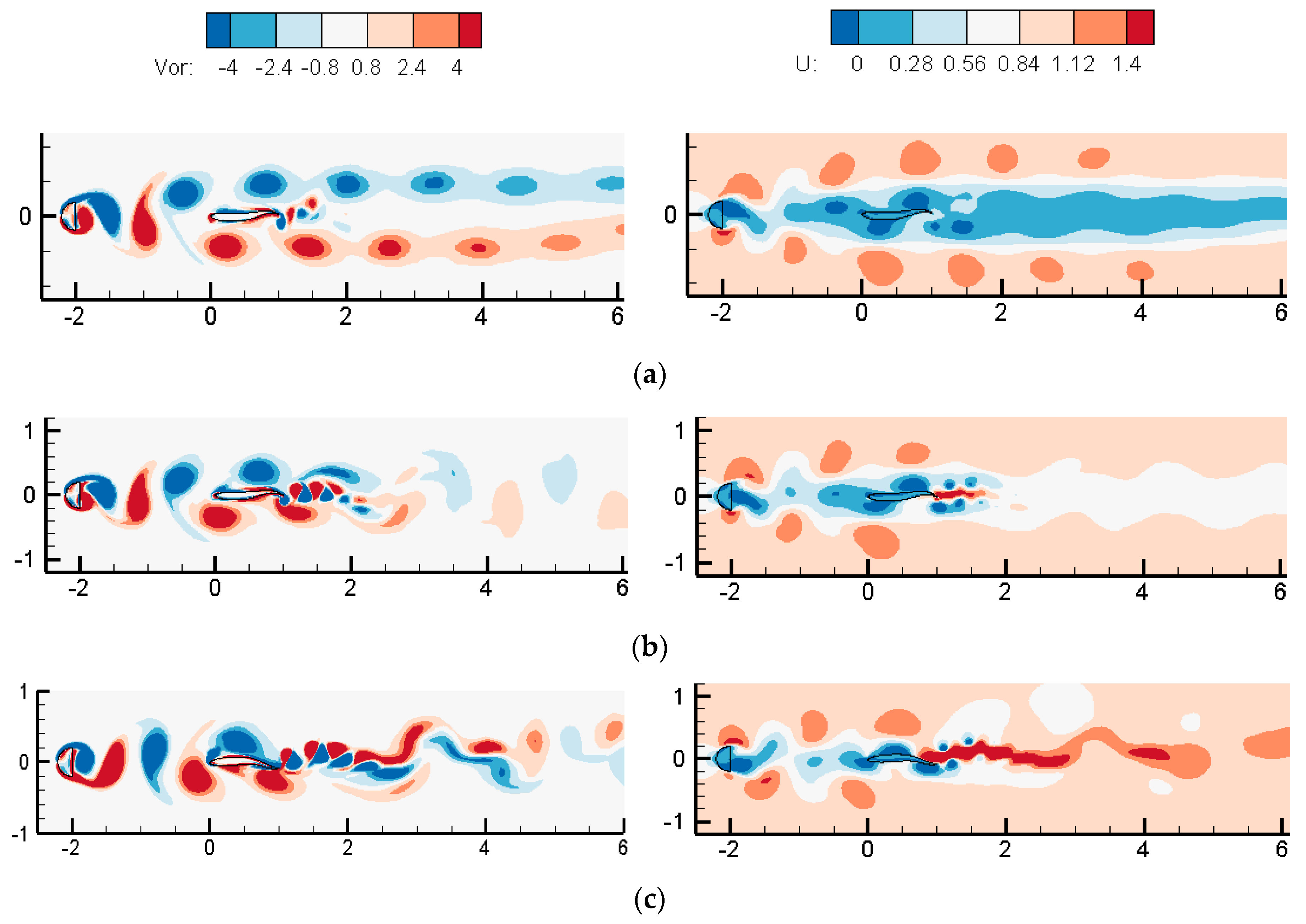
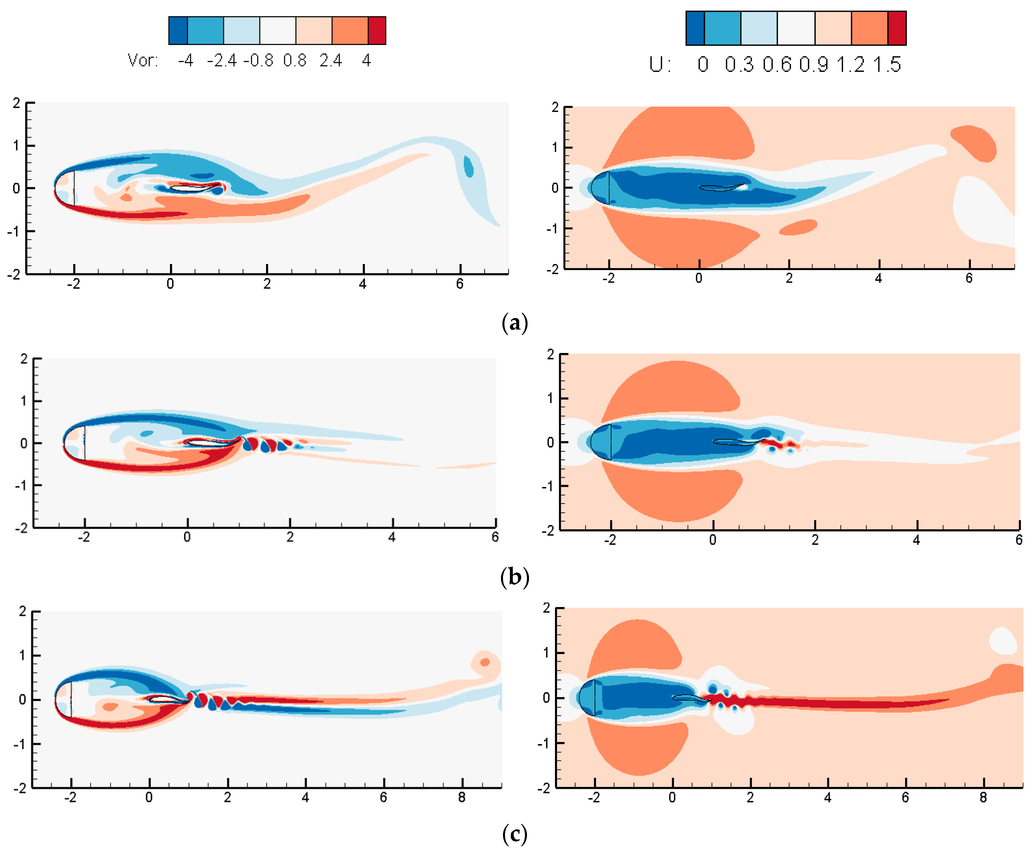
3.1.2. Wake Dynamics

To reveal the physical mechanism in fish swimming, this section emphasizes the wake structures around the downstream fish. Figure 11, Figure 12 and Figure 13 show the instantaneous vortex structures on the left and the velocity contours on the right surrounding the downstream fish at three Strouhal numbers for Ls/L = 0.3, 1, and 2. For a narrow gap distance of Ls/L = 0.3, as seen in Figure 11, a pair of shear layers could not be shed from the cylinder due to the splitting and blocking effects of the fish. At St = 0.2, the long shear layers were shed from the tail of the undulating fish, forming alternative shedding vortices. The conventional von-Kármán (CvK) vortex streets were observed with a large streamwise and crosswise width. The vortex streets span a large streamwise distance of over 5 L where the vortex intensity gradually attenuates in the far downstream region. At St = 0.6, a neutral wake was formed behind the fish with the vortices spanning in one row. The neutral wake with a tight arrangement covered a streamwise distance of 2 L, while the von-Kármán vortex street with a large crosswise width was generated in the far downstream. This von-Kármán vortex street dissipated quickly after traveling the distance of 2 L. For a larger Strouhal number of St = 1, the wake transited into the reverse von-Kármán vortex (RvK) mode where the positive and negative vortices were arranged in the upper and lower sides, respectively. The streamwise and crosswise distances between two rows of vortices became smaller, while they were enlarged as they travelled to the far downstream.
It is known that the generation of the thrust is commonly accompanied by the RvK vortex street [39,40,41]. However, the RvK vortex mode does not correspond exactly to the generation of thrust. It was found by Ma et al. [42] and Zhu et al. [43] that the drag-to-thrust transition lagged behind the transition of the Cvk to RvK modes in the flows around a pitching airfoil. In contrast, the thrust was generated for both the CvK vortex street and the reverse one in the present study. The causes of the thrust generation can be explained from the velocity field. The fish is situated in a momentum deficit region created by the upstream cylinder, as seen to the right side of Figure 11. At St = 0.2, the wake velocity of the fish was higher than the incoming flow around the fish. The incremented momentum led to the formation of the thrust. The wake velocity of the fish rose, as seen in Figure 11b, as the St increased, leading to the thrust enhancement. In particular, at St = 1, a horizontal and high velocity jet spanning a long distance of over 4 L was generated behind the fish, creating a very large thrust.
The wake patterns for Ls/L = 1 and 2 were very distinct from those for Ls/L = 0.3. For Ls/L = 1 and 2, the alternative shedding vortices of the cylinder could be fully developed before they impinged on the nose of the fish. The periodic impact from the upstream vortex shedding causes a strong wake interaction in the downstream, which compromises the sinusoidal variation of the force coefficients on the fish in Figure 3, Figure 4 and Figure 5. For Ls/L = 1 in Figure 12, a pair of vortices from the upstream cylinder hit the nose of the downstream fish alternatively in each period. When hit by the negative vortex, the fish splits the vortex into two parts with different strengths. The vortex with high strength is rolled along the upper surface of the fish to the far wake region. The vortex with weak strength dissipates and disappears rapidly. In contrast, the split vortex with high strength coalesces with the positive vortex in the down side of the fish when the positive vortex hits the fish and is split into two parts. Consequently, the vortices behind the undulating fish are enhanced due to the fusion of the vortices with the same rotational directions. Two rows of stable and connected vortex streets are formed. In addition, the CvK vortex streets caused by the upstream cylinder created a momentum deficit region, leading to the reduction in the drag in Figure 3a. There was also a momentum deficit region behind the downstream fish at St = 0.2 due to the CvK vortex pattern in Figure 12a. The fish encounters the positive or negative drag, which can be manifested from the velocity difference between the front and rear of the fish.
At St = 0.6 in Figure 12b, the wake of the downstream fish transited into the RvK vortex pattern. The positive and negative vortices were tightly arranged in the upper and lower sides, respectively. Some vortices from the cylinder merged with those by the fish to enhance the vortex strength. There were also some vortices rolling up freely and dissipating in the wake region. The intensity of the tightly arranged vortex streets faded away after a horizontal distance of 3 L. Correspondingly, it was shown in the velocity contours that a momentum surfeit region behind the fish was generated. A lateral velocity jet with a length of 2 L was apparently observed behind the fish. This generated a negative drag, namely the positive thrust, on the undulating fish according to momentum conservation. At St = 1, the RvK vortex pattern was obviously presented with narrower streamwise and crosswise widths in the near wake region. Moreover, a new RvK vortex pattern was generated in the far wake region with large streamwise and crosswise widths. Correspondingly, a streamwise velocity jet with a length of over 4 L formed behind the fish. Therefore, the momentum surfeit region behind the fish is enhanced, augmenting the thrust.
In Figure 13, there were two pairs of intact negative and positive vortices when the fish was further away from the cylinder for Ls/L = 2. The wake patterns at three Strouhal numbers were similar to those in Figure 12. Note that the vortex shedding of the cylinder was nearly synchronous with that generated by the downstream fish at St = 0.2, strengthening the coalescing of the vortices downstream. Consequently, two parallel vortex strips with a length of over 5 L were formed.

3.2. Influences of the Cylindrical Diameter

In Section 3.1, the radius of the upstream cylinder was equal to the oscillation amplitude of the fish. It is interesting to investigate how the size of the cylinder influences the downstream fish, since aquatic organisms can encounter upstream obstacles with various sizes in reality.
In this section, three diameters of the upstream cylinder were considered with D/L = 0.2, 0.4, and 0.8 to examine their effects on the dynamic and wake patterns of the downstream fish. The corresponding test cases of #4, #6 and #7 are listed in Table 2. The gap spacing between the cylinder and the fish was Ls/L = 2. The wave number of the fish was set as k = 2π. The physical model and the computational parameters were set the same as those in Section 3.1. The simulation was conducted on a non-uniform Cartesian grid with a middle grid of Δ x min = 0.004 L and Δ y min = 0.00267 L.
Figure 14, Figure 15 and Figure 16 present the time evolution of the force coefficients for different diameters of the cylinder at three Strouhal numbers, respectively. At St = 0.2, the sinusoidal variation patterns of the force coefficients observed in the fish-only case were disrupted by the cylinder. Moreover, the disruption on the fish was more severe, and the oscillation amplitude of the force coefficients was larger for a bigger diameter. For D/L = 0.8, both the drag and lift coefficients showed very irregular and chaotic variation trends with periodically varied amplitudes and equilibrium positions in Figure 15. The drag coefficient was reduced remarkably as the diameter of the cylinder was enlarged. The fish could experience negative drag, namely the thrust, in an entire undulating cycle for D/L = 0.8. The drag reduction can be explained by the fact that the upstream cylinder creates a momentum deficit region, shielding the downstream fish. More vortex flows are blocked by the cylinder for a larger diameter. At St = 0.6 or 1, the drag coefficient displayed regular oscillation pattern with a slightly flat crest and steep trough. The lift coefficient showed a nearly sinusoidal oscillation pattern. The cylinder exerted minor effects on the downstream fish at a higher St. The dynamic characteristics of the fish were dominated by its undulating motion.
To further observe the force variation patterns of the fish, the amplitude spectra of the lift force by the FFT for D/L = 0.4 and 0.8 at St = 0.2 and 0.6 were investigated, as seen in Figure 17 and Figure 18. At St = 0.2, the force variations on the fish were dominated by two contributions: one was from the undulating fish with the frequency fe, and the other may be caused by the attached shear layers on the upstream cylinder with the vortex shedding frequency fc. The two contributions are comparable in Figure 17, leading to the chaotic force variation in Figure 14. As the St rose to 0.6, the peak of the CL-spectrum at fe enlarged five times, while the peak of the CL-spectrum at fc only showed a slight increase, as seen in Figure 19. Therefore, the contribution of the vortical flow from the upstream cylinder can be ignored compared with that of the undulating fish.
The average drag ( C D a v g ) and RMS lift ( C L r m s ) coefficients on the downstream fish for different diameters of the cylinder were also examined, as shown in Figure 19. The C D a v g was reduced and the C L r m s grew remarkably with the increase in the St. Additionally, the thrust was enhanced for different diameters of the cylinder compared with the fish-only case. The thrust enhancement was more evident for a larger diameter of the cylinder, especially at a large St. It was noted that the fish encountered negative drag for D/L = 0.8 at various Strouhal numbers. The stationary fish could even drift toward the upstream cylinder. In contrast, the C L r m s for different diameters as well as the fish-only case were much closer. Specifically, the C L r m s for D/L = 0.4 was slightly larger than that for D/L = 0.2 and 0.8, and the fish-only case in Figure 19b. Consequently, the undulating fish behind the cylinder can gain remarkable thrust enhancement with a slight increase in the lift, thus the swimming efficiency can be enhanced.
To quantitatively evaluate the swimming efficiency η, Figure 20 presents the swimming efficiency η of the fish against the St for various diameters of the cylinder. The η of the fish for three diameters was higher than that for the fish-only at various Strouhal numbers. The fish could gain a higher η for a larger upstream cylinder. In particular, the efficiency enhancement was more significant at a smaller St. The critical St* became small as the diameter of the cylinder enlarged when the drag transitioned into the thrust. The critical St* was 0.6 for the fish-only case, 0.4 for D/L = 0.2, and 0.2 for D/L = 0.4. A critical St* did not exist for D/L = 0.8, since the fish could swim forward at any St, even at the stationary state. As the St increased, the η of the fish for three diameters was reduced dramatically. It converged close to 0.12 at St = 1.2 for three diameters, slightly larger than that of the fish-only, which is consistent with that in Section 3.1. The understanding of the influence of the cylindrical diameter is potentially helpful for habitat management and the design of fish passageways.
To reproduce the hydrodynamic interaction of the cylinder and fish, Figure 21 and Figure 22 show the instantaneous vorticity (left) and velocity (right) contours surrounding the fish for D/L = 0.4 and 0.8 at three Strouhal numbers. The fluid field for D/L = 0.2 is referenced in Figure 14. There were distinct disparities on the wake structures for three diameters of the cylinder. As the diameter was enlarged from D/L = 0.2 to D/L = 0.4, large transverse and horizontal distances of the vortex streets were generated by the cylinder. The fish could drift between the two rows of vortex streets. In the momentum deficit region created by the upstream cylinder, the downstream fish experienced a critical state transiting from the CvK vortex pattern to the reverse one in Figure 21a, although it undulated at a small St. The vortex streets behind the fish were tightly arranged, and their sizes were much smaller than those from the upstream cylinder. These were rolled up within the gap between the negative and positive vortices with relative independence.
At St = 0.6, the alternative vortices were shed at a faster speed and interacted with the vortices from the upstream cylinder. The intensities of the vortices gradually dissipated at a length of 2 L downstream of the fish due to the fusion between the negative and positive vortices. Meanwhile, the RvK vortex streets produced a momentum surfeit region behind the fish, causing the positive thrust. A horizontal velocity jet with a length of 2 L presented in the velocity contours apparently. At a higher St in Figure 21c, there occurred a strong interaction of the vortices by the upper cylinder and the fish. The wake vortices with high intensity were shed toward the far downstream and deflected to one side. The deflected wake was also observed in [21], which can be contributed to the pairing pattern of the downstream wake [44]. Moreover, the deflection direction is determined by the initial direction of the undulating motion. In addition, a streamwise velocity jet with a length of over 4 L was manifested, revealing a large thrust.
For a larger diameter of D/L = 0.8, a pair of large shear layers was attached on the cylinder. The shear layers were large and long enough to cover the downstream fish. In turn, the downstream fish hindered the detachment of the shear layers. Consequently, the alternative vortex shedding in the gap generated by the cylinder for D/L = 0.2 and 0.4 was not observed. At St = 0.2, the shear layers on the cylinder were reattached to the downstream fish, forming a pair of elongated vortices covering the fish in Figure 22a. The fish undulated in a small frequency, imposing negligible effects on the large vortices. Therefore, the elongated vortices can be shed in the far downstream region.
As the St increased to 0.6, an RvK vortex pattern with narrow streamwise and transverse width was generated in Figure 22b. However, the vortex intensity dissipated quickly after covering a length of 2 L. The rapid undulation of the fish disrupted the detachment of the large vortices on the cylinder. For a larger Strouhal number of St = 1, RvK vortex streets with a compact arrangement was extended to the far downstream. Regarding the velocity contours, the fish was situated in the momentum deficit region created by the upstream cylinder. The velocity in front of the fish was smaller than that behind the fish, leading to the generation of the thrust. At St = 0.2, there existed a local high velocity around the tail of the fish in Figure 22a, and the reaction force propelled the fish forward. At St = 0.6, a horizontal and high velocity jet with a length of L was created. In addition, the horizontal velocity jet had a length of over 3 L at St = 1, giving rise to a larger thrust.

4. Conclusions

This study numerically investigated the dynamic and wake characteristics of an undulating fish behind an upstream cylinder. The numerical model employed a robust ghost cell method to handle the flows around the complex rigid and flexible boundaries. Based on this numerical model, we examined the impacts of the location and diameter of the upstream cylinder on the force coefficient, swimming efficiency, and the wake structures of the downstream fish under various Strouhal numbers.
The dynamic features of the downstream fish were noticeably influenced by the upstream cylinder, especially for a small St. The average drag coefficients on the downstream fish for different diameters and locations of the cylinder were significantly smaller than those in the fish-only case, since a momentum deficit region was created behind the cylinder. However, the RMS lift coefficients nearly coincided with or without the upstream cylinder. This revealed that the downstream fish can swim faster without adding muscle activities. In addition, the stationary fish could hold in place and even drift upstream in the incoming flow for Ls/L = 0.3 or D/L = 0.8. The downstream fish could gain efficiency enhancement for different locations and diameters of the upstream cylinder, which was more significant at a smaller St.
At Ls/L = 0.3 and D/L = 0.2, the wake pattern transformed from the CvK vortex street at St = 0.2 to the reversed one at St = 0.6. The velocity jet behind the fish generated a reaction force, namely the thrust, on the fish according to the momentum conservation. The fish experienced the thrust at various Strouhal numbers. This revealed that the generation of the thrust is not inevitably accompanied by the reversed von-Kármán vortex street. As the gap distance rose to Ls/L = 1 and 2, strong wake interaction occurred in the downstream. The fish splits the vortex into two parts with different strengths, and the split vortices coalesce with the wake generated by the undulating fish. As the cylindrical diameter is enlarged, the fish can drift through two rows of vortex streets with a large width. The deflected wake in the far downstream was observed at St = 1.
The 2D fish model cannot fully reveal the flow characteristics of a real fish due to the significant 3D effects. The present method can be easily extended to simulate 3D flexible boundary flows. In the near future, we will investigate the hydrodynamic interaction of multiple 3D undulating fishes in tandem or parallel arrangements.

Author Contributions

Conceptualization, J.X.; Methodology, X.C.; Software, J.X.; Validation, J.X.; Formal analysis, X.C.; Investigation, B.M.; Resources, B.M.; Data curation, B.M.; Writing—original draft, X.C.; Writing—review & editing, B.M. and J.X.; Funding acquisition, X.C. and J.X. All authors have read and agreed to the published version of the manuscript.

Funding

This research was funded by the Foundation from China COSCO Shipping Corporation Limited (No. 2023-1-Z001-03) and the Natural Science Foundation of Zhejiang Province, China (No. 11LY21E090001).

Institutional Review Board Statement

Not applicable.

Informed Consent Statement

Not applicable.

Data Availability Statement

The original contributions presented in the study are included in the article.

Conflicts of Interest

Author Xing Chang and Bowen Ma were employed by Shanghai Ship and Shipping Research Institute Co. Ltd. The remaining authors declare that the research was conducted in the absence of any commercial or financial relationships that could be construed as potential conflicts of interest.

References

  1. Castro-Santos, T.; Goerig, E.; He, P.; Lauder, G.V. Applied Aspects of Locomotion and Biomechanics; Academic Press Fish Physiology: Cambridge, MA, USA, 2022; pp. 91–140. [Google Scholar]
  2. Lighthill, M.J. Large-amplitude elongated-body theory of fish locomotion. Proc. R. Soc. Lond. 1971, 179, 125–138. [Google Scholar]
  3. Wu, Y.T. Swimming of a waving plate. J. Fluid Mech. 1961, 10, 321–344. [Google Scholar] [CrossRef]
  4. Cheng, J.Y.; Zhuang, L.X.; Tong, B.G. Analysis of Swimming Three-dimensional Waving Plates. J. Fluid Mech. 1991, 232, 341–355. [Google Scholar] [CrossRef]
  5. Eloy, C. Optimal Strouhal number for swimming animals. J. Fluids Struct. 2011, 30, 205–218. [Google Scholar] [CrossRef]
  6. Wu, Y.T. Fish swimming and bird/insect flight. Annu. Rev. Fluid Mech. 2011, 43, 25–58. [Google Scholar] [CrossRef]
  7. Tu, H.; Wang, F.; Wang, H.; Gao, Q.; Wei, R. Experimental study on wake flows of a live fish with time-resolved tomographic PIV and pressure reconstruction. Exp. Fluids 2022, 63, 25. [Google Scholar] [CrossRef]
  8. Piskur, P.; Szymak, P.; Przybylski, M.; Naus, K.; Jaskólski, K.; Żokowski, M. Innovative energy-saving propulsion system for low-speed biomimetic underwater vehicles. Energies 2021, 14, 8418. [Google Scholar] [CrossRef]
  9. Piskur, P. Strouhal Number Measurement for Novel Biomimetic Folding Fins Using an Image Processing Method. J. Mar. Sci. Eng. 2022, 10, 484. [Google Scholar] [CrossRef]
  10. Wei, C.; Hu, Q.; Liu, Y.; Yin, S.; Ji, X. Performance evaluation and optimization for two-dimensional fish-like propulsion. Ocean Eng. 2021, 233, 109191. [Google Scholar] [CrossRef]
  11. Zhao, Z.; Dou, L. Effects of the structural relationships between the fish body and caudal fin on the propulsive performance of fish. Ocean Eng. 2019, 186, 106117. [Google Scholar] [CrossRef]
  12. Lauder, G.V.; Han, P. Hydrodynamics of median-fin interactions in fish-like locomotion: Effects of fin shape and movement. Phys. Fluids 2020, 32, 011902. [Google Scholar]
  13. Li, N.Y.; Zhuang, J.Y.; Zhu, Y.Z.; Su, G.S.; Yu, Y.M. Fluid dynamics of a self-propelled biomimetic underwater vehicle with pectoral fins. J. Ocean Eng. Sci. 2021, 6, 160–169. [Google Scholar] [CrossRef]
  14. Sun, P.N.; Colagrossi, A.; Zhang, A.M. Numerical simulation of the self-propulsive motion of a fishlike swimming foil using the δ+-sph model. Theor. Appl. Mech. Lett. 2018, 8, 115–125. [Google Scholar] [CrossRef]
  15. Verzicco, R. Immersed Boundary Methods: Historical Perspective and Future Outlook. Annu. Rev. Fluid Mech. 2023, 55, 129–155. [Google Scholar] [CrossRef]
  16. Huang, W.X.; Tian, F.B. Recent trends and progress in the immersed boundary method. J. Mech. Eng. Sci. 2019, 233, 095440621984260. [Google Scholar] [CrossRef]
  17. Wang, W.; Yan, Y.; Tian, F.B. Numerical study on hydrodynamics for a non-sinusoidal forced oscillating hydrofoil based on an immersed boundary method. Ocean Eng. 2017, 147, 606–620. [Google Scholar] [CrossRef]
  18. Ghommem, M.; Bourantas, G.C.; Wittek, A.; Miller, K.; Hajj, M.R. Hydrodynamic modeling and performance analysis of bio-inspired swimming. Ocean Eng. 2020, 197, 106897. [Google Scholar] [CrossRef]
  19. Romano, D.; Stefanini, C. Individual neon tetras (Paracheirodon innesi, myers) optimise their position in the group depending on external selective contexts: Lesson learned from a fish-robot hybrid school. Biosyst. Eng. 2021, 204, 170–180. [Google Scholar] [CrossRef]
  20. Deng, J.; Shao, X.M.; Yu, Z.S. Hydrodynamic studies on two traveling wavy foils in tandem arrangement. Phys. Fluids 2007, 19, 305–371. [Google Scholar] [CrossRef]
  21. Khalid, M.S.U.; Akhtar, I.; Dong, H. Hydrodynamics of a tandem fish school with asynchronous undulation of individuals. J. Fluids Struct. 2016, 66, 19–35. [Google Scholar] [CrossRef]
  22. Dai, L.Z.; He, G.W.; Zhang, X.; Zhang, X. Stable formations of self-propelled fish-like swimmers induced by hydrodynamic interactions. J. R. Soc. Interface 2018, 15, 20180490. [Google Scholar] [CrossRef] [PubMed]
  23. Kurt, M.; Mivehchi, A.; Moored, K.W. Two-dimensionally stable self-organization arises in simple schooling swimmers through hydrodynamic interactions. Physics 2021, 10, 14. [Google Scholar]
  24. Feng, Y.K.; Liu, H.X.; Su, Y.Y.; Su, Y.M. Numerical study on the hydrodynamics of c-turn maneuvering of a tuna-like fish body under self-propulsion. J. Fluid Struct. 2020, 94, 102954. [Google Scholar] [CrossRef]
  25. Hemelrijk, C.; Reid, D.; Hildenbrandt, H.; Padding, J. The increased efficiency of fish swimming in a school. Fish Fish. 2015, 16, 12072. [Google Scholar] [CrossRef]
  26. Liao, J.C. Fish exploiting vortices decrease muscle activity. Science 2003, 302, 1566–1569. [Google Scholar] [CrossRef] [PubMed]
  27. Liao, J.; Beal, D.; Lauder, G.; Triantafyllou, M. The Kármán gait: Novel body kinematics of rainbow trout swimming in a vortex street. J. Exp. Biol. 2003, 206, 1059–1073. [Google Scholar] [CrossRef] [PubMed]
  28. Beal, D.N.; Hover, F.S.; Triantafyllou, M.S.; Liao, J.C.; Lauder, G.V. Passive propulsion in vortex wakes. J. Fluid Mech. 2006, 549, 385–402. [Google Scholar] [CrossRef]
  29. Sahu, M.M.S. Numerical study of flow-induced vibration of a circular cylinder with attached flexible splitter plate at low re. J. Fluid Mech. 2019, 880, 551–593. [Google Scholar] [CrossRef]
  30. Mao, Q.; Zhao, J.; Liu, Y.; Sung, H.J. Drag reduction by a rotationally oscillating cylinder with a flexible filament. Phys. Fluids 2022, 34, 041910. [Google Scholar] [CrossRef]
  31. Sun, X.; Suh, C.S.; Ye, Z.H.; Yu, B. Dynamics of a circular cylinder with an attached splitter plate in laminar flow: A transition from vortex-induced vibration to galloping. Phys. Fluids 2020, 32, 027104. [Google Scholar] [CrossRef]
  32. Hu, L.C.; Liu, N.S.; Hang, D.; Lu, X.Y. Study on flapping modes of a flexible filament in the wake of an upstream rotating cylinder. Sci. Sin. Phys. Mech. Astron. 2018, 48, 094706. [Google Scholar] [CrossRef]
  33. Shi, F.L.; Xin, J.J.; Yin, P.D.; Dong, Y.H. A GPU accelerated three-dimensional ghost cell method with an improved implicit surface representation for complex rigid or flexible boundary flows. Comput. Phys. Commun. 2024, 298, 109098. [Google Scholar] [CrossRef]
  34. Xin, J.J.; Shi, F.L.; Jin, Q.; Lin, C. A radial basis function based ghost cell method with improved mass conservation for complex moving boundary flows. Comput. Fluids 2018, 176, 210–225. [Google Scholar] [CrossRef]
  35. Dong, G.J.; Lu, X.Y. Characteristics of flow over traveling wavy foils in a side-by-side arrangement. Phys. Fluids 2007, 19, 057107. [Google Scholar] [CrossRef]
  36. Paraz, F.; Schouveiler, L.; Eloy, C. Thrust generation by a heaving flexible foil: Resonance, nonlinearities, and optimality. Phys. Fluids 2016, 28, 011903. [Google Scholar] [CrossRef]
  37. Liao, J.C. Fish swimming efficiency. Curr. Biol. 2022, 32, R589–R683. [Google Scholar] [CrossRef]
  38. Borazjani, I.; Sotiropoulos, F. On the role of form and kinematics on the hydrodynamics of self-propelled body/caudal fin swimming. J. Exp. Biol. 2010, 213, 89–107. [Google Scholar] [CrossRef] [PubMed]
  39. Triantafyllou, M.S.; Triantafyllou, G.S.; Yue, D.K.P. Hydrodynamics of fishlike swimming. Ann. Rev. Fluid Mech. 2000, 32, 33–53. [Google Scholar] [CrossRef]
  40. Liu, N.; Peng, Y.L.; Liang, Y.; Lu, X. Flow over a traveling wavy foil with a passively flapping flat plate. Phys. Rev. E 2012, 85, 056316. [Google Scholar] [CrossRef]
  41. Wang, H.L.; Zheng, X.B.; Pröbsting, S.; Hu, C.H.; Wang, Q. An unsteady RANS simulation of the performance of an oscillating hydrofoil at a high Reynolds number. Ocean Eng. 2023, 274, 114097. [Google Scholar] [CrossRef]
  42. Ma, D.C.; Qiu, Z.; Li, G.H.; Wang, F.X. Numerical investigation on lag mechanism of drag-to-thrust transition for a pitching airfoil. Acta Aerodyn. Sin. 2021, 39, 91–103. [Google Scholar]
  43. Zhu, B.; Wang, F.L.; Xu, W.J.; Xiao, Q.S. Mode transition mechanisms in semi-passive flapping-wing propulsion or energy extraction. Phys. Fluids 2023, 35, 123604. [Google Scholar] [CrossRef]
  44. Zheng, Z.C.; Wei, Z. Study of mechanisms and factors that influence the formation of vortical wake of a heaving airfoil. Phys. Fluids 2012, 24, 103601. [Google Scholar] [CrossRef]
Figure 1. Geometrical model of the fish swimming and the boundary conditions.
Jmse 12 01254 g001
Figure 2. Time history of the force coefficients for three grids at St = 0.4: (a) drag coefficient; (b) lift coefficient [21].
Jmse 12 01254 g002
Figure 3. Force coefficients against time for different gap distances at St = 0.2: (a) CD; (b) CL.
Jmse 12 01254 g003
Figure 4. Force coefficients against time for different gap distances at St = 0.6: (a) CD; (b) CL.
Jmse 12 01254 g004
Figure 6. Amplitude spectra of the lift coefficient for three gap distances at St = 0.2: (a) Ls/L = 0.3; (b) Ls/L = 1; (c) Ls/L = 2.
Jmse 12 01254 g006
Figure 7. Amplitude spectra of the lift coefficient for three gap distances at St = 0.6: (a) Ls/L = 0.3; (b) Ls/L = 1; (c) Ls/L = 2.
Jmse 12 01254 g007
Figure 8. Amplitude spectra of the lift coefficient for three gap distances at St = 1: (a) Ls/L = 0.3; (b) Ls/L = 1; (c) Ls/L = 2.
Jmse 12 01254 g008
Figure 9. Average drag ( C D a v g ) and RMS lift ( C L r m s ) coefficients as a function of the Strouhal number: (a) C D a v g ; (b) C L r m s .
Jmse 12 01254 g009
Figure 10. Swimming efficiency of the fish for different gap distances as the function of the St.
Jmse 12 01254 g010
Figure 11. Instantaneous vorticity and velocity contours surrounding the fish for Ls/L = 0.3 at three Strouhal numbers. (a) St = 0.2. (b) St = 0.6. (c) St = 1.
Jmse 12 01254 g011
Figure 12. Instantaneous vorticity and velocity contours surrounding the fish for Ls/L = 1 at three St: (a) St = 0.2; (b) St = 0.6; (c) St = 1.
Jmse 12 01254 g012
Figure 13. Instantaneous vorticity and velocity contours surrounding the fish for Ls/L = 2 at three St: (a) St = 0.2; (b) St = 0.6; (c) St = 1.
Jmse 12 01254 g013
Figure 14. Time evolution of the force coefficients for different diameters at St = 0.2: (a) CD; (b) CL.
Jmse 12 01254 g014
Figure 15. Time evolution of the force coefficients for different diameters at St = 0.6: (a) CD; (b) CL.
Jmse 12 01254 g015
Figure 16. Time evolution of the force coefficients for different diameters at St = 1: (a) CD; (b) CL.
Jmse 12 01254 g016
Figure 17. Amplitude spectra of the lift force for two diameters at St = 0.2: (a) D/L = 0.4; (b) D/L = 0.8.
Jmse 12 01254 g017
Figure 18. Amplitude spectra of the lift force for two diameters at St = 0.6: (a) D/L = 0.4; (b) D/L = 0.8.
Jmse 12 01254 g018
Figure 19. Force coefficients on the downstream fish for different diameters as a function of St: (a) C D a v g ; (b) C L r m s .
Jmse 12 01254 g019
Figure 20. Swimming efficiency η of the fish as a function of St.
Jmse 12 01254 g020
Figure 21. Instantaneous vorticity and velocity contours surrounding the fish for D/L = 0.4 at three St: (a) St = 0.2; (b) St = 0.6; (c) St = 1.
Jmse 12 01254 g021
Figure 22. Instantaneous vorticity and velocity contours surrounding the fish for D/L = 0.8 at three St: (a) St = 0.2; (b) St = 0.6; (c) St = 1.
Jmse 12 01254 g022
Table 1. Grid information for the convergence tests at St = 0.4.
Grid NotationGrid Number Δ x min , Δ y min C L m a x C D a v g
G1250 × 1000.006, 0.0041.490.101
G2375 × 1500.004, 0.002671.660.103
G3562 × 2250.00267, 0.001781.680.103
Table 2. Test conditions for fish swimming behind a cylinder.
Test ConditionDiameterGap DistanceStrouhal Number
Case #1--0–1.2
Case #2D/L = 0.2Ls/L = 0.30–1.2
Case #3D/L = 0.2Ls/L = 10–1.2
Case #4D/L = 0.2Ls/L = 20–1.2
Case #5D/L = 0.2Ls/L = 40–1.2
Case #6D/L = 0.4Ls/L = 20–1.2
Case #7D/L = 0.8Ls/L = 20–1.2
Disclaimer/Publisher’s Note: The statements, opinions and data contained in all publications are solely those of the individual author(s) and contributor(s) and not of MDPI and/or the editor(s). MDPI and/or the editor(s) disclaim responsibility for any injury to people or property resulting from any ideas, methods, instructions or products referred to in the content.

