
A Hybrid Fuzzy LQR-PI Blade Pitch Control Scheme for Spar-Type Floating Offshore Wind Turbines


Abstract
1. Introduction
2. FOWT Modeling
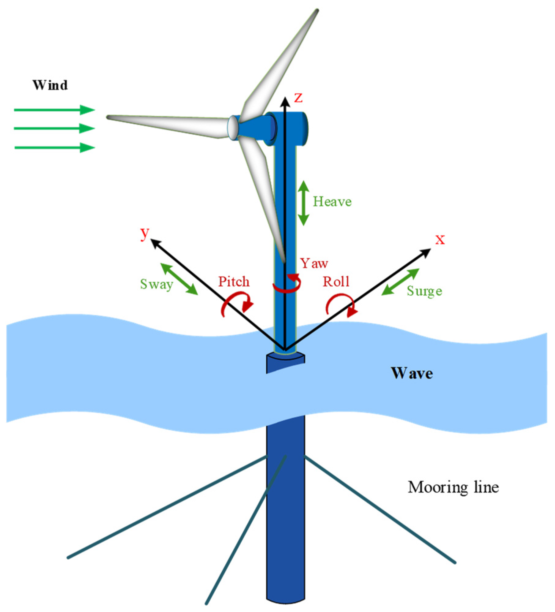
2.1. Spar-Type FOWT
2.2. Dynamics Modeling
2.2.1. Aerodynamic Model
2.2.2. Drivetrain Model
2.2.3. Generator Model
2.3. Reduced-Order Model
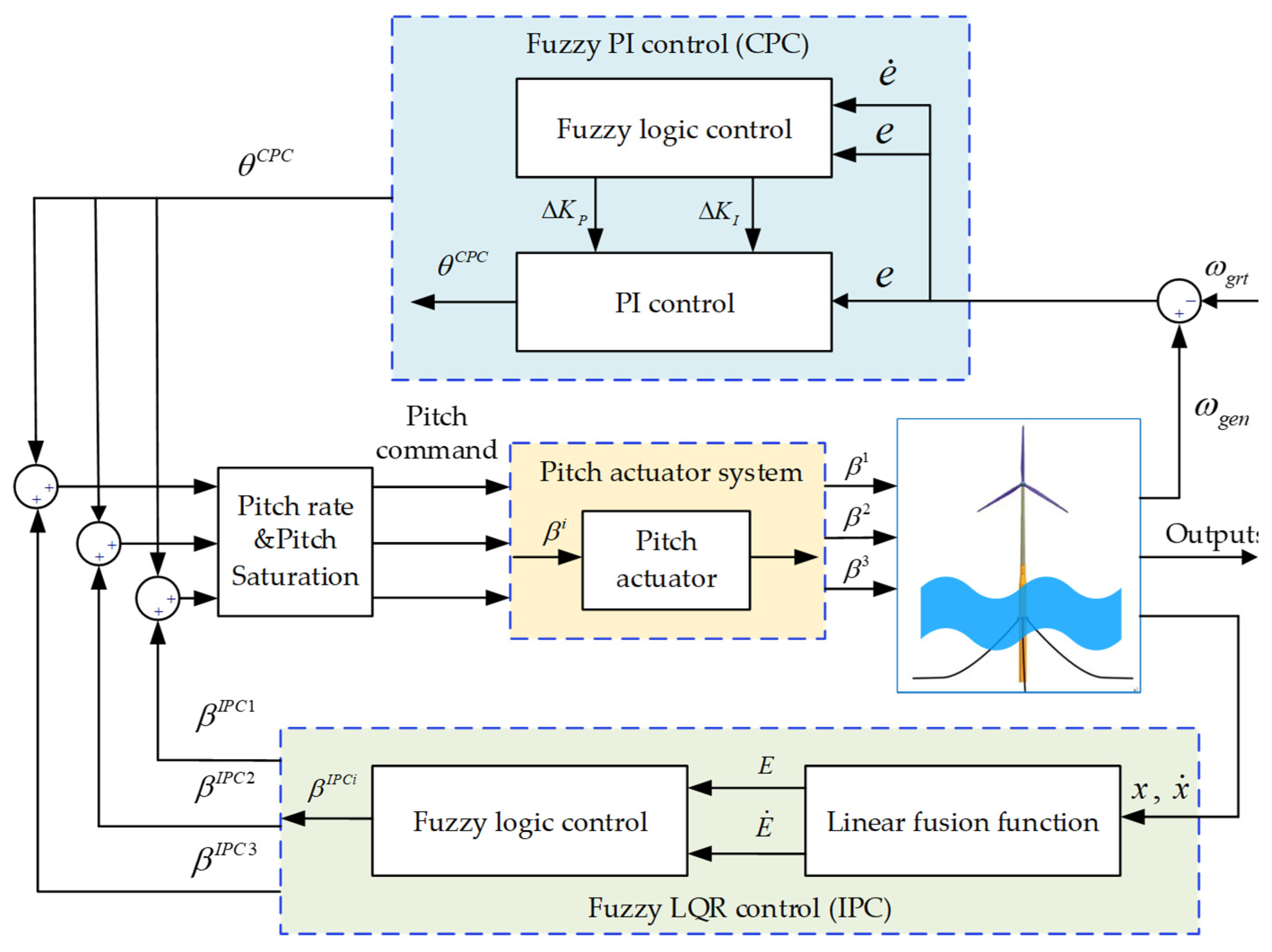
3. Control Scheme
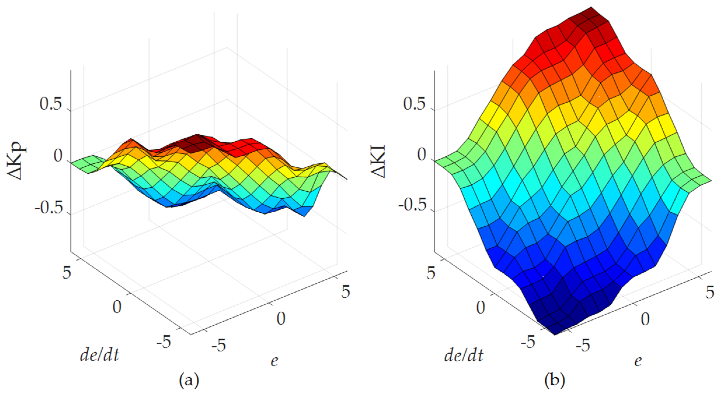
3.1. Fuzzy PI Control
3.2. Fuzzy LQR Control
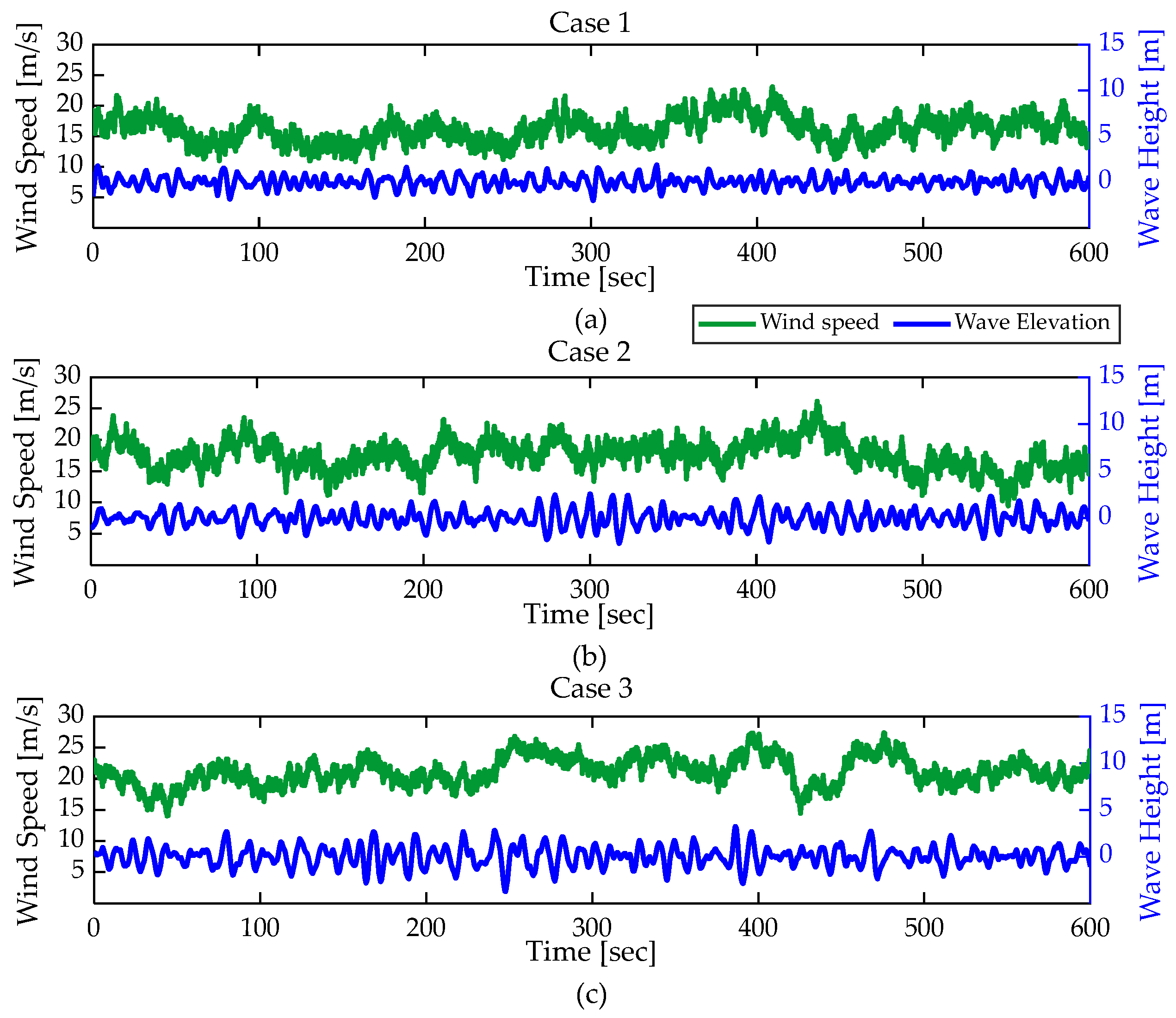
4. Simulation Results and Discussion
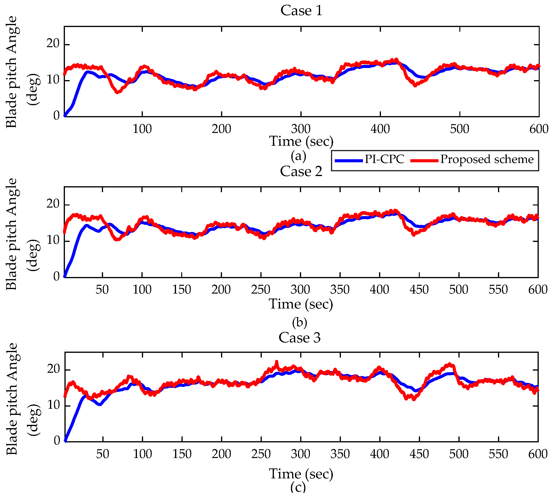
4.1. Time-Domain Analysis
4.1.1. Power and Speed Regulation
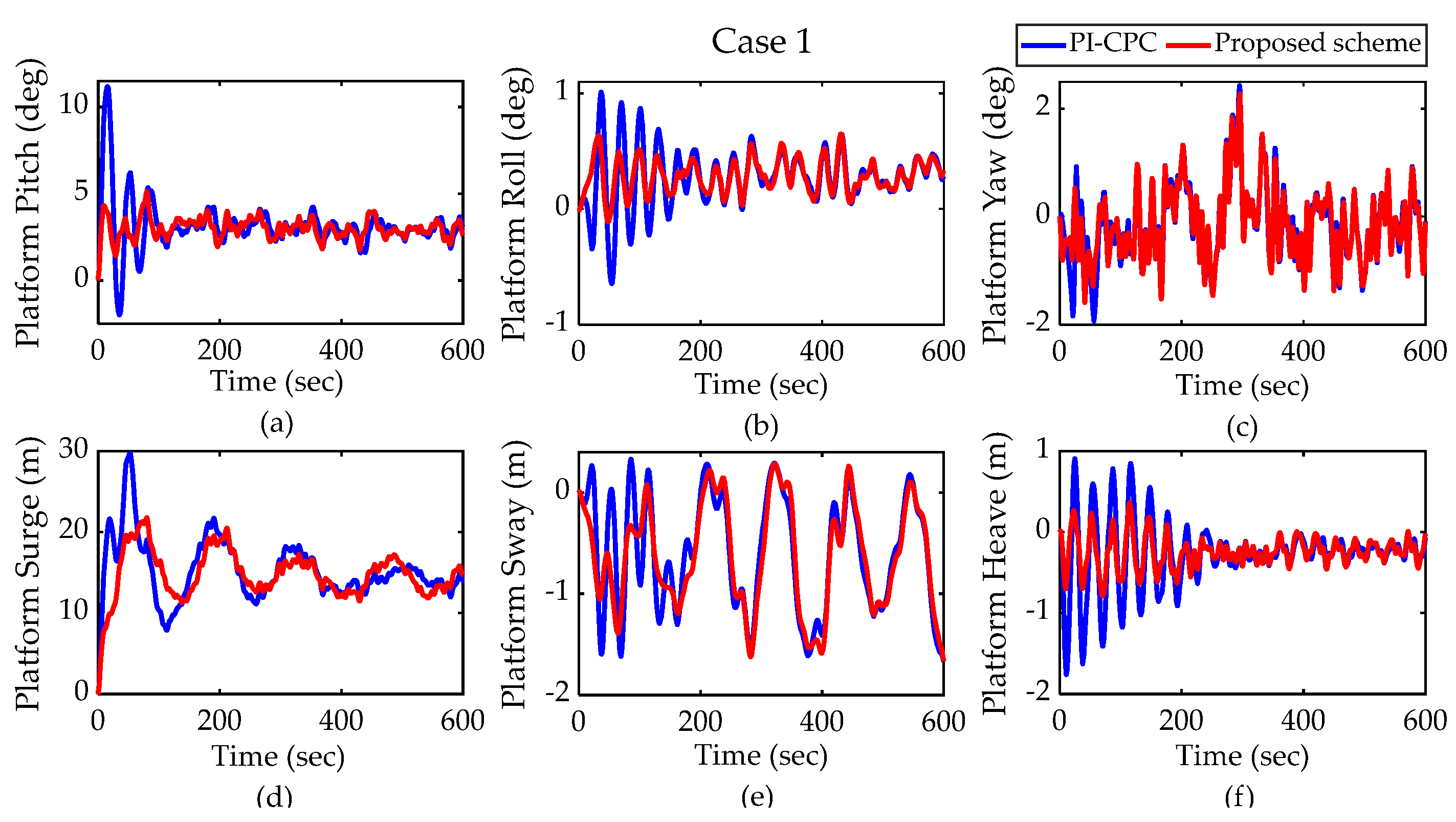
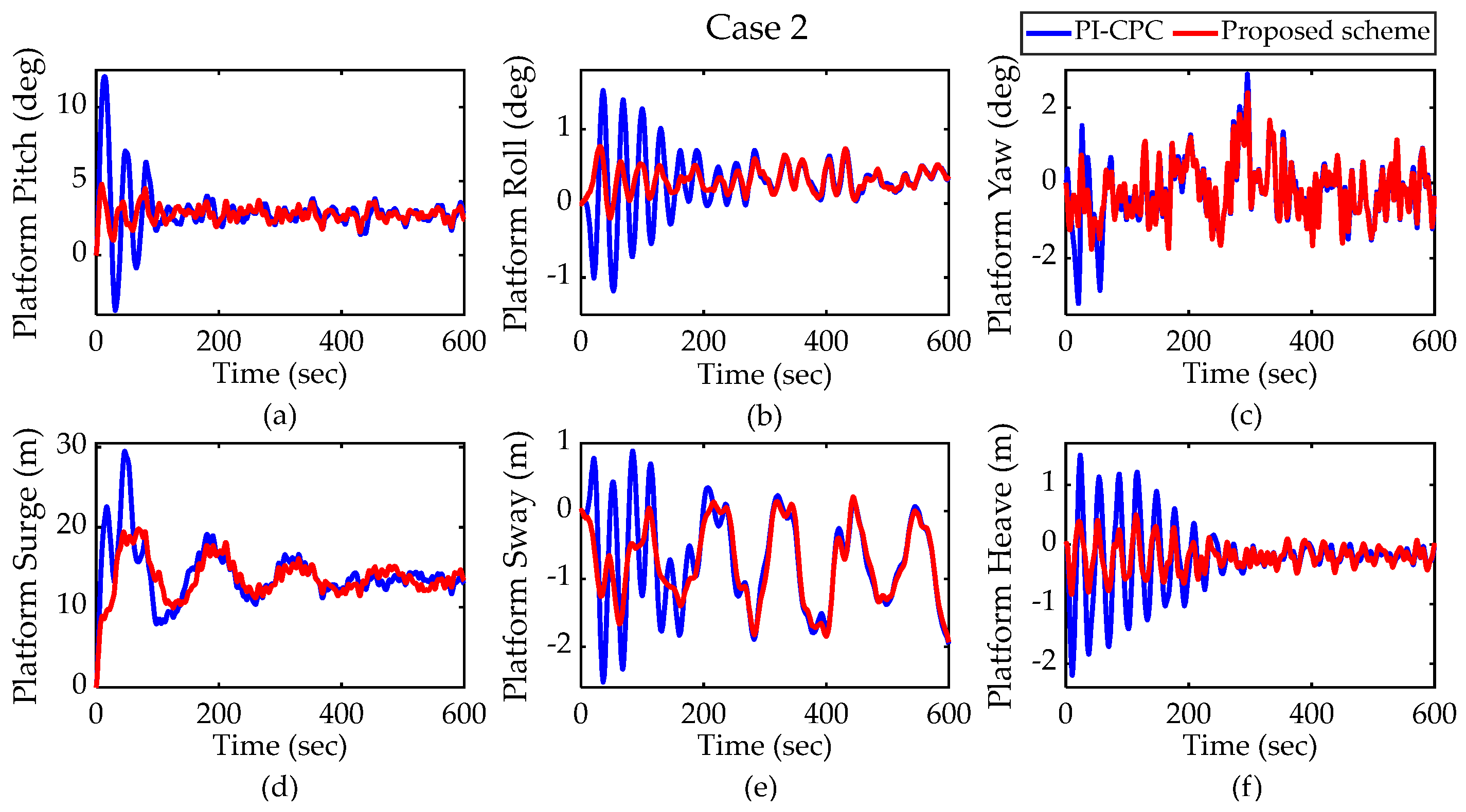
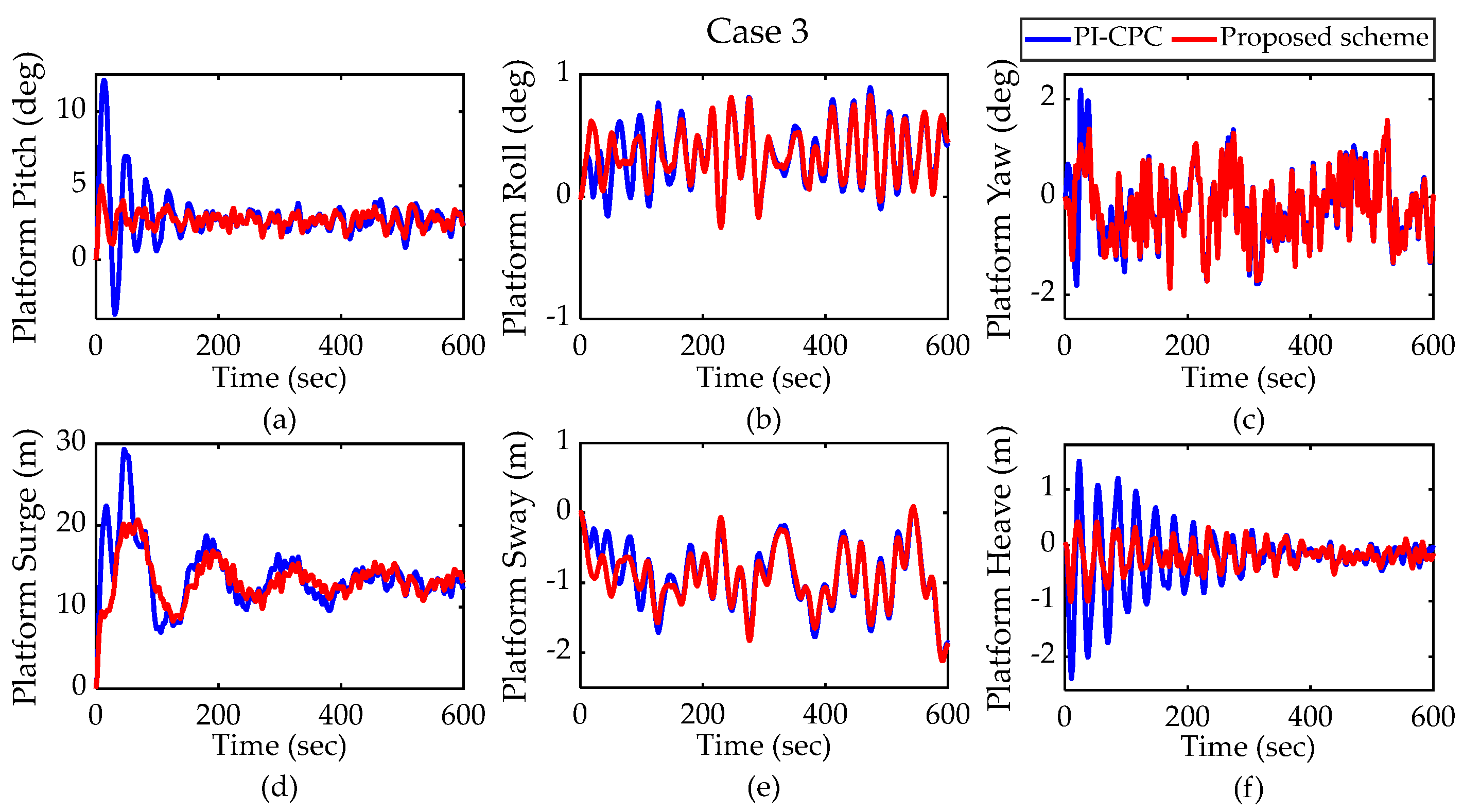
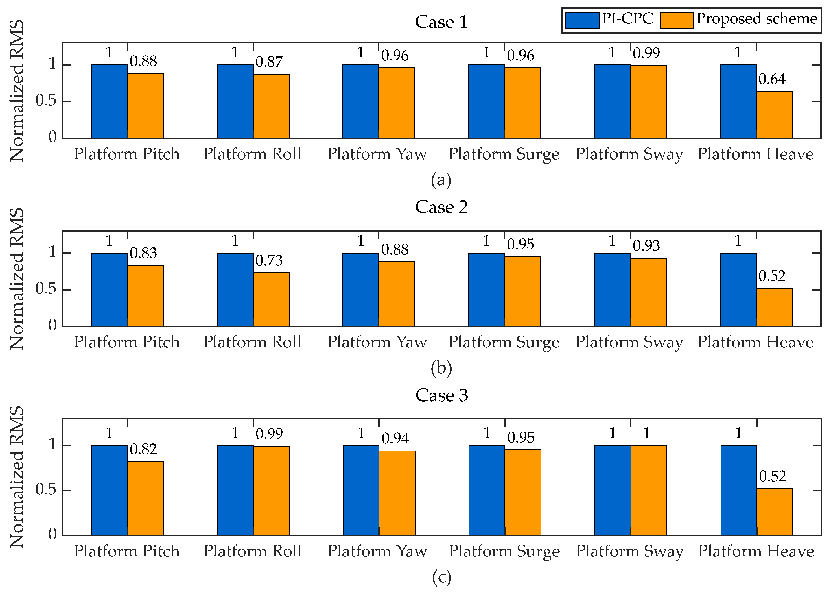
4.1.2. Platform Motion Response
4.1.3. Structural Loads Response
4.2. Power Spectral Density Analysis
4.2.1. Output Power Response
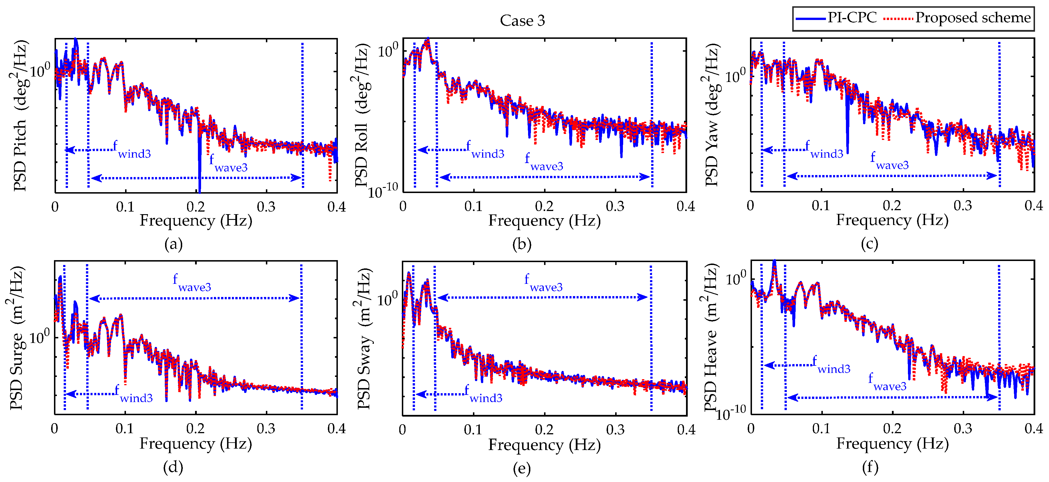
4.2.2. Platform Motion Response
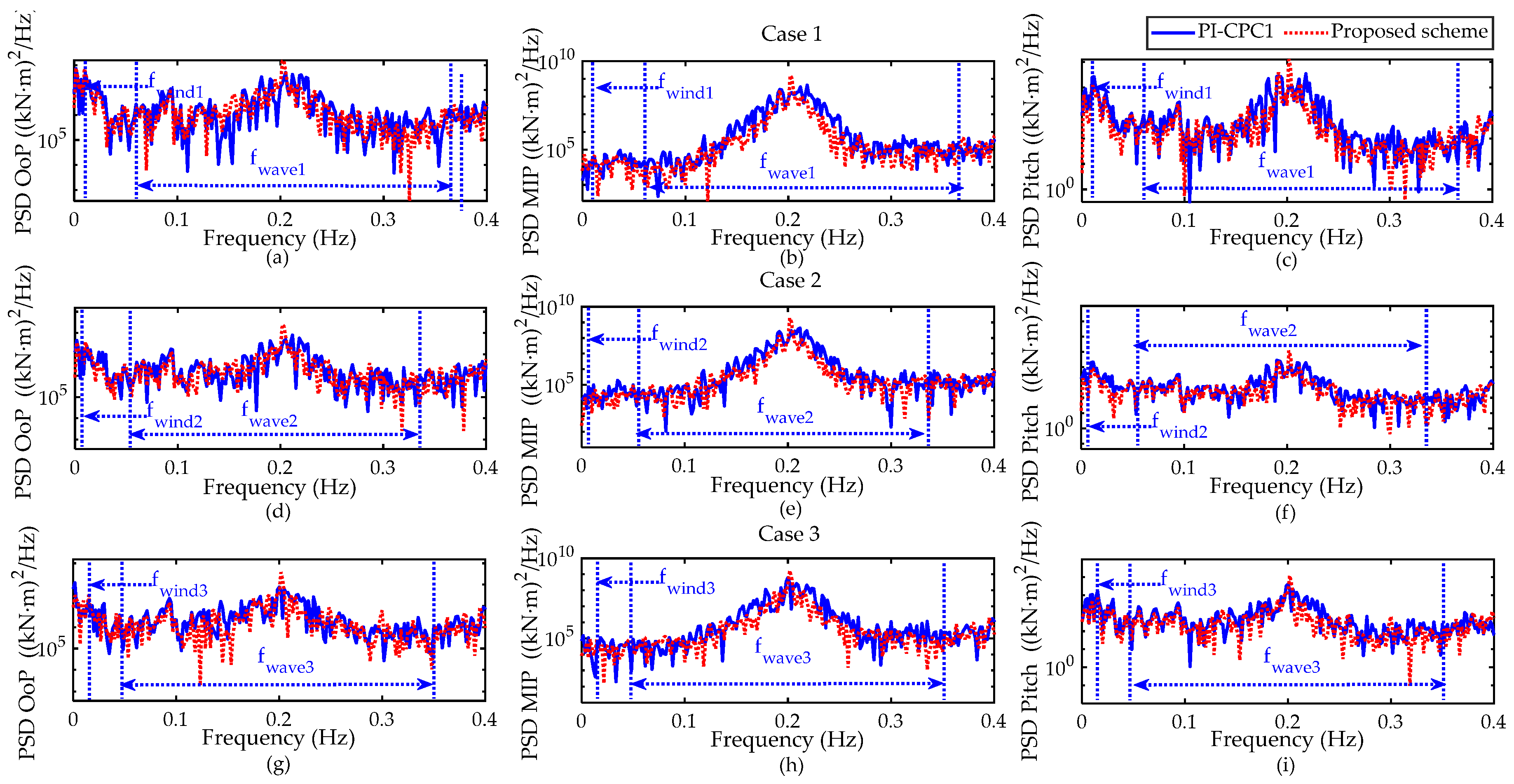
4.2.3. Fatigue Load Response
5. Conclusions
Author Contributions
Funding
Institutional Review Board Statement
Informed Consent Statement
Data Availability Statement
Conflicts of Interest
References
- López-Queija, J.; Robles, E.; Jugo, J.; Alonso-Quesada, S. Review of Control Technologies for Floating Offshore Wind Turbines. Renew. Sustain. Energy Rev. 2022, 167, 112787. [Google Scholar] [CrossRef]
- Zhang, C. A Contribution to the Nonlinear Control of Floating Wind Turbines. Ph.D. Thesis, École Centrale de Nantes, Nantes, France, 2021. [Google Scholar]
- Didier, F.; Liu, Y.-C.; Laghrouche, S.; Depernet, D. A Comprehensive Review on Advanced Control Methods for Floating Offshore Wind Turbine Systems above the Rated Wind Speed. Energies 2024, 17, 2257. [Google Scholar] [CrossRef]
- Shah, K.A.; Meng, F.; Li, Y.; Nagamune, R.; Zhou, Y.; Ren, Z.; Jiang, Z. A Synthesis of Feasible Control Methods for Floating Offshore Wind Turbine System Dynamics. Renew. Sustain. Energy Rev. 2021, 151, 111525. [Google Scholar] [CrossRef]
- Lackner, M.A. An Investigation of Variable Power Collective Pitch Control for Load Mitigation of Floating Offshore Wind Turbines. Wind Energy 2013, 16, 435–444. [Google Scholar] [CrossRef]
- Schipf, D.; Simley, E.; Lemmer, F.; Pao, L.; Cheng, P.W. Collective Pitch Feedforward Control of Floating Wind Turbines Using Lidar. In Proceedings of the Twenty-Fifth International Ocean and Polar Engineering Conference, Kona, HI, USA, 21 June 2015. [Google Scholar]
- Wakui, T.; Yoshimura, M.; Yokoyama, R. Novel Parameter Settings for Gain-Scheduled Feedback Control of Rotational Speed in a Floating Offshore Wind Turbine–Generator System. Wind Eng. 2017, 41, 26–42. [Google Scholar] [CrossRef]
- Bagherieh, O.; Nagamune, R. Utilization of Blade Pitch Control in Low Wind Speed for Floating Offshore Wind Turbines. In Proceedings of the 2014 American Control Conference, Portland, OR, USA, 4–6 June 2014; pp. 4354–4359. [Google Scholar] [CrossRef]
- Zhang, C.; Plestan, F. Individual/Collective Blade Pitch Control of Floating Wind Turbine Based on Adaptive Second Order Sliding Mode. Ocean Eng. 2021, 228, 108897. [Google Scholar] [CrossRef]
- Namik, H. Individual Blade Pitch and Disturbance Accommodating Control of Floating Offshore Wind Turbines. Ph.D. Thesis, The University of Auckland, Auckland, New Zealand, 2012. [Google Scholar]
- Ossmann, D.; Theis, J.; Seiler, P. Load Reduction on a Clipper Liberty Wind Turbine with Linear Parameter-Varying Individual Blade Pitch Control. Wind Energy 2017, 20, 1771–1786. [Google Scholar] [CrossRef]
- Bossanyi, E.A.; Fleming, P.A.; Wright, A.D. Validation of Individual Pitch Control by Field Tests on Two- and Three-Bladed Wind Turbines. IEEE Trans. Control Syst. Technol. 2013, 21, 1067–1078. [Google Scholar] [CrossRef]
- Routray, A.; Sivakumar, N.; Hur, S.; Bang, D. A Comparative Study of Optimal Individual Pitch Control Methods. Sustainability 2023, 15, 10933. [Google Scholar] [CrossRef]
- Zhou, Z.; Li, S. Self-Sustained and Coordinated Rhythmic Deformations with SMA for Controller-Free Locomotion. Adv. Intell. Syst. 2024, 6, 2300667. [Google Scholar] [CrossRef]
- Ma, R.; Siaw, F.L.; Thio, T.H.G.; Yang, W. New Adaptive Super-Twisting Extended-State Observer-Based Sliding Mode Scheme with Application to FOWT Pitch Control. J. Mar. Sci. Eng. 2024, 12, 902. [Google Scholar] [CrossRef]
- Yuan, Y.; Tang, J. On Advanced Control Methods toward Power Capture and Load Mitigation in Wind Turbines. Engineering 2017, 3, 494–503. [Google Scholar] [CrossRef]
- Tang, J.; Dai, K.; Luo, Y.; Bezabeh, M.A.; Ding, Z. Integrated Control Strategy for the Vibration Mitigation of Wind Turbines Based on Pitch Angle Control and TMDI Systems. Eng. Struct. 2024, 303, 117529. [Google Scholar] [CrossRef]
- Kipchirchir, E.; Söffker, D. IPC-Based Robust Disturbance Accommodating Control for Load Mitigation and Speed Regulation of Wind Turbines. Wind Energy 2024, 27, 382–402. [Google Scholar] [CrossRef]
- Yuan, Y.; Tang, J. Adaptive Pitch Control of Wind Turbine for Load Mitigation under Structural Uncertainties. Renew. Energy 2017, 105, 483–494. [Google Scholar] [CrossRef]
- Shah, K.A.; Li, Y.; Nagamune, R.; Zhou, Y.; Ur Rehman, W. Platform Motion Minimization Using Model Predictive Control of a Floating Offshore Wind Turbine. Theor. Appl. Mech. Lett. 2021, 11, 100295. [Google Scholar] [CrossRef]
- Sarkar, S.; Fitzgerald, B.; Basu, B. Nonlinear Model Predictive Control to Reduce Pitch Actuation of Floating Offshore Wind Turbines. IFAC-PapersOnLine 2020, 53, 12783–12788. [Google Scholar] [CrossRef]
- Hara, N.; Tsujimoto, S.; Nihei, Y.; Iijima, K.; Konishi, K. Experimental Validation of Model-Based Blade Pitch Controller Design for Floating Wind Turbines: System Identification Approach. Wind Energy 2017, 20, 1187–1206. [Google Scholar] [CrossRef]
- Wakui, T.; Nagamura, A.; Yokoyama, R. Stabilization of Power Output and Platform Motion of a Floating Offshore Wind Turbine-Generator System Using Model Predictive Control Based on Previewed Disturbances. Renew. Energy 2021, 173, 105–127. [Google Scholar] [CrossRef]
- Ramos, R.L. Linear Quadratic Optimal Control of a Spar-Type Floating Offshore Wind Turbine in the Presence of Turbulent Wind and Different Sea States. J. Mar. Sci. Eng. 2018, 6, 151. [Google Scholar] [CrossRef]
- da Cunha Barroso Ramos, R.L. Linear Quadratic Regulation for a 10-MW Tension Leg Platform Floating Offshore Wind Turbine Operating under Normal and Extreme Turbulence Model Conditions. Mar. Syst. Ocean. Technol. 2024. [Google Scholar] [CrossRef]
- Lemmer, F.; Schlipf, D.; Cheng, P.W. Control Design Methods for Floating Wind Turbines for Optimal Disturbance Rejection. J. Phys. Conf. Ser. 2016, 753, 092006. [Google Scholar] [CrossRef]
- Christiansen, S.; Knudsen, T.; Bak, T. Optimal Control of a Ballast-Stabilized Floating Wind Turbine. In Proceedings of the 2011 IEEE International Symposium on Computer-Aided Control System Design (CACSD), Denver, CO, USA, 28–30 September 2011; pp. 1214–1219. [Google Scholar]
- Abadi, A.S.S.; Hosseinabadi, P.A.; Mekhilef, S. Fuzzy Adaptive Fixed-Time Sliding Mode Control with State Observer for A Class of High-Order Mismatched Uncertain Systems. Int. J. Control Autom. Syst. 2020, 18, 2492–2508. [Google Scholar] [CrossRef]
- Yin, S.; Shi, P.; Yang, H. Adaptive Fuzzy Control of Strict-Feedback Nonlinear Time-Delay Systems With Unmodeled Dynamics. IEEE Trans. Cybern. 2016, 46, 1926–1938. [Google Scholar] [CrossRef] [PubMed]
- Jonkman, J. Definition of the Floating System for Phase IV of OC3; National Renewable Energy Laboratory (NREL): Golden, CO, USA, 2010. [Google Scholar]
- Roh, C.; Ha, Y.-J.; Ahn, H.-J.; Kim, K.-H. A Comparative Analysis of the Characteristics of Platform Motion of a Floating Offshore Wind Turbine Based on Pitch Controllers. Energies 2022, 15, 716. [Google Scholar] [CrossRef]
- Jonkman, J.; Butterfield, S.; Musial, W.; Scott, G. Definition of a 5-MW Reference Wind Turbine for Offshore System Development; National Renewable Energy Laboratory (NREL): Golden, CO, USA, 2009. [Google Scholar]
- Guenoune, I.; Plestan, F.; Chermitti, A.; Evangelista, C. Modeling and Robust Control of a Twin Wind Turbines Structure. Control Eng. Pract. 2017, 69, 23–35. [Google Scholar] [CrossRef]
- Asgharnia, A.; Shahnazi, R.; Jamali, A. Performance and Robustness of Optimal Fractional Fuzzy PID Controllers for Pitch Control of a Wind Turbine Using Chaotic Optimization Algorithms. ISA Trans. 2018, 79, 27–44. [Google Scholar] [CrossRef]
- Li, L.; Gao, Z.; Moan, T. Joint Environmental Data at Five European Offshore Sites for Design of Combined Wind and Wave Energy Devices. In Proceedings of the ASME 2013 32nd International Conference on Ocean, Offshore and Arctic Engineering, American Society of Mechanical Engineers Digital Collection, Nantes, France, 9–14 June 2013. [Google Scholar]
- Jonkman, B.J.; Buhl, M.L., Jr. TurbSim User’s Guide; National Renewable Energy Laboratory (NREL): Golden, CO, USA, 2006. [Google Scholar]
- Hayman, G.J.; Buhl, M.L., Jr. Mlife Users Guide for Version 1.00; National Renewable Energy Laboratory(NREL): Golden, CO, USA, 2012. [Google Scholar]


| Parameter | Value |
|---|---|
| Rated Power | 5 MW |
| Number of blades | 3 |
| Rotor Orientation | Upwind |
| Rotor, Hub Diameter | 126 m, 3 m |
| Hub Height | 90 m |
| Cut-in, Rated, Cut-out wind Speed | 3 m/s, 11.4 m/s, 25 m/s |
| Cut-in, Rated Rotor Speed | 6.9 rpm, 12.1 rpm |
| Blade Pitch Angle setting | 0°~90° |
| Blade Pitch rate | −8°/s~8°/s |
| Draft | 120 m |
| Platform Mass | 7.466 × 10⁶ kg |
| Tower Mass | 347,460 kg |
| Rotor Mass | 110,000 kg |
| Nacelle Mass | 240,000 kg |
| Pitch Inertia | m2 |
| Roll Inertia | m2 |
| Yaw Inertia | m2 |
| Cable Stiffness | 3.842 × 10⁸ N |
| N | Z | P | ||
| N | N | N | N | |
| Z | N | P | P | |
| P | P | P | P | |
| Case No. | Wind Speed (m/s) | Turbulence Intensity (%) | Wave Height HS (m) | Peak Spectral Period TP (s) |
|---|---|---|---|---|
| 1 | 16 | 13.17 | 3.0 | 10.5 |
| 2 | 18 | 12.67 | 3.6 | 10.9 |
| 3 | 20 | 12.48 | 4.1 | 11.2 |
| RMS | Generator Power (kW) | Generator Speed (rpm) | |
|---|---|---|---|
| Control Strategy | |||
| Case 1 | PI-CPC | 5512 | 1222.5 |
| Proposed scheme | 5293 | 1173.8 | |
| Case 2 | PI-CPC | 5554 | 1231.8 |
| Proposed scheme | 5298 | 1175.0 | |
| Case 3 | PI-CPC | 5547 | 1230.1 |
| Proposed scheme | 5294 | 1174.2 |
Disclaimer/Publisher’s Note: The statements, opinions and data contained in all publications are solely those of the individual author(s) and contributor(s) and not of MDPI and/or the editor(s). MDPI and/or the editor(s) disclaim responsibility for any injury to people or property resulting from any ideas, methods, instructions or products referred to in the content. |
© 2024 by the authors. Licensee MDPI, Basel, Switzerland. This article is an open access article distributed under the terms and conditions of the Creative Commons Attribution (CC BY) license (https://creativecommons.org/licenses/by/4.0/).
Share and Cite
Ma, R.; Siaw, F.L.; Thio, T.H.G. A Hybrid Fuzzy LQR-PI Blade Pitch Control Scheme for Spar-Type Floating Offshore Wind Turbines. J. Mar. Sci. Eng. 2024, 12, 1306. https://doi.org/10.3390/jmse12081306
Ma R, Siaw FL, Thio THG. A Hybrid Fuzzy LQR-PI Blade Pitch Control Scheme for Spar-Type Floating Offshore Wind Turbines. Journal of Marine Science and Engineering. 2024; 12(8):1306. https://doi.org/10.3390/jmse12081306
Chicago/Turabian StyleMa, Ronglin, Fei Lu Siaw, and Tzer Hwai Gilbert Thio. 2024. "A Hybrid Fuzzy LQR-PI Blade Pitch Control Scheme for Spar-Type Floating Offshore Wind Turbines" Journal of Marine Science and Engineering 12, no. 8: 1306. https://doi.org/10.3390/jmse12081306
APA StyleMa, R., Siaw, F. L., & Thio, T. H. G. (2024). A Hybrid Fuzzy LQR-PI Blade Pitch Control Scheme for Spar-Type Floating Offshore Wind Turbines. Journal of Marine Science and Engineering, 12(8), 1306. https://doi.org/10.3390/jmse12081306