Article

Field Redevelopment and Weight Shedding for Decommissioning of Offshore Facilities

by
Ahmed Reda
1,*,
Chiemela Victor Amaechi
2,3,4,
Mohamed A. Shahin
1 and
Kristoffer K. McKee
1
1
School of Civil and Mechanical Engineering, Curtin University, Perth, WA 6102, Australia
2
School of Engineering, Lancaster University, Lancaster LA1 4YR, UK
3
Department of Construction Management, Global Banking School, Manchester M12 6JH, UK
4
Institute of Energy Infrastructure, National Energy University, Kajang 43009, Malaysia
*
Author to whom correspondence should be addressed.
J. Mar. Sci. Eng. 2024, 12(8), 1331; https://doi.org/10.3390/jmse12081331
Submission received: 5 June 2024 / Revised: 28 July 2024 / Accepted: 3 August 2024 / Published: 6 August 2024
(This article belongs to the Section Marine Energy)

Abstract

:
There is currently a rising interest in reusing and repurposing offshore facilities through decommissioning; however, major challenges arise, such as size, weight, sea depth, planned use, and location. This article aims to discuss the philosophy that needs to be adopted for field redevelopment, particularly when existing platforms must be preserved and integrated into new greenfield facilities. The article also discusses the concept of weight shedding during the decommissioning of offshore facilities to either extend the life of existing platforms or provide clear space for new equipment to be installed by removing unnecessary components and structures. The above aspects of decommissioning are investigated through the redevelopment of a case study of a mature offshore oil field located in shallow water. The study indicated that weight shedding presents a favourable method for decommissioning offshore installations and can effectively lower expenses, minimise environmental consequences, and optimise the use of resources.

1. Introduction

Offshore oil and gas production has been crucial in fulfilling the world’s energy needs, resulting in the establishment of various offshore facilities across the globe [1,2,3,4,5,6,7,8,9]. When such facilities reach the end of their operating lives, decommissioning is required to guarantee safety, safeguard the environment, and comply with the regulations [10,11]. Decommissioning is the process of eliminating or deserting offshore structures, pipelines, and related infrastructure when production has ceased. The decommissioning process entails meticulous planning and approval procedures, as well as the plugging and abandoning of wells. It also involves ensuring that offshore facilities are free of hydrocarbons, removing and either reusing, recycling, or disposing of all or parts of the installation, and ultimately restoring the site to its former state [5,6,7,8,9]. A multitude of offshore fields have been in production for more than half a century and successfully extracted vast quantities of oil, and several fixed offshore constructions required decommissioning because their remaining lifespan is insufficient due to corrosion or worries about piling capacity. Furthermore, a significant number of ageing wellhead jackets have also been decommissioned either because they have integrity problems or contain few remaining reserves [1,2,3,4].
Recent research has highlighted the significance of decommissioning in the offshore industry [1,2,3,4,5,6,7,8,9,10,11,12,13,14,15,16]. More recently, there has been a rising interest in the decommissioning and reuse of offshore facilities; however, there are still some challenging factors, such as size, weight, sea depth, planned use, and location. When offshore oil and gas production facilities are near the end of their operating lifespans, decommissioning becomes essential to address, and the practical concerns include weight shedding, cost savings, and safety and environmental considerations [16,17,18].
While decommissioning cost models were proposed by [17,18], a predictive model for pipeline decommissioning was also proposed by [19]. Currently, there is an abundance of literature that covers different aspects of the decommissioning of offshore structures [13,14,15,20]; however, there is also a gap in the literature on weight shedding during the decommissioning process of offshore platforms. Some studies have also highlighted the environmental and regulation issues that the operator may face if weight shedding during the decommissioning is not considered carefully [21,22,23]. Another aspect that has been highlighted in the literature is the legislative and legal aspects of decommissioning [24,25,26], while other studies considered the cost implications of decommissioning [17,27]. Some other studies proposed strategies for decommissioning [28,29,30], and included aspects of planning, logistics, and relocation of the decommissioned offshore facilities [15,22,31].
There is an immense need to have a weight shedding model for the decommissioning of offshore facilities. Conventional decommissioning procedures usually entail the total extraction of structures, which can be expensive, intricate, and environmentally destructive. However, weight shedding presents a unique alternative to conventional decommissioning procedures by selectively eliminating non-essential components and structures to decrease the total weight of the facility before final decommissioning. This article examines the practicality, advantages, and difficulties of adopting a weight-shedding decommissioning approach for the installation of offshore facilities. The article also provides a comprehensive examination of the weight-shedding process. A case study and associated practical examples are also provided to illustrate the potential advantages and difficulties of this strategy. In addition, this article discusses potential areas for future research and prospects for innovation in the field of weight-shedding decommissioning and emphasises the prospects for sustainable and cost-effective decommissioning procedures in the offshore industry. Furthermore, Appendices A and B present the general strategy of decommissioning abandonment and decommissioning breakdown, respectively.

2. Case Study

As mentioned previously, this research presents an innovative method for decommissioning offshore facilities by reducing their weight. The objective is to lower costs, minimise environmental effects, and optimise the use of resources. The concept entails carefully eliminating non-essential components and structures to decrease the total weight of the facility before its final decommissioning. In principle, weight shedding refers to the deliberate and organised process of eliminating superfluous components and structures from offshore facilities to decrease their total weight. The basics of weight reduction involve identifying superfluous objects, analysing their structural soundness, assessing potential hazards, and ensuring adherence to regulations. It is important to take into account strategic considerations when trying to lose weight. Effective implementation of a weight-reduction decommissioning strategy requires strategic planning. Key considerations encompass the facility’s architectural configuration, past performance, surrounding ecological circumstances, and obligatory regulations. Another factor to consider is the feasibility evaluation of weight reduction, which is performed to ascertain the practicality of implementing weight-reduction measures for a certain offshore facility. This evaluation takes into account various criteria such as the soundness of the structure, potential risks to safety, influence on the environment, cost-effectiveness, and involvement of stakeholders. The above aspects will be investigated through a case study that covers the weight-shedding methodology; the removal of the assets has to be performed after the installation of the new greenfield assets. Figure 1 shows the field layout of the case study considered, whereas Figure 2 shows the assets that will be removed (highlighted in red) and those that will be modified (highlighted in purple), as well as the new greenfield developments (highlighted in yellow). The weight-shedding scope covers removals from two installations, including platforms PS-2C = 775 t and PS-3B = 850 t (only this platform will be discussed in this article).

2.1. Field Description

The field of the case study considered in this paper is a mature offshore oil field located in the shallow waters of the Arabian Gulf, approximately 100 km east of the Qatari coastline. This field has been producing oil and associated gas for over 50 years, with the production rates continuously declining. The existing facilities have already exceeded their design life whilst a significant quantity of oil and gas reserves remain to be recovered from the reservoirs. However, such potential cannot be realised through the existing facilities alone due to ageing and/or specific process requirements. The field has an existing central production PS-3B and several remote wellhead platforms (hereafter commonly referred to as WHJs) with one or more wells. Fluid from the WHJs is transported through a network of subsea pipelines to their respective production stations. Each production station complex has eight bridge-linked platforms where oil, water, and gas are separated and processed. The new redevelopment of this field aims to extend the life of the field by 30 years, by maximising the use of the existing facilities and installing new facilities. This is carried out to support the forecasted production profiles, as will be discussed herein. The existing production complex facilities and platforms are largely redundant and are considered for decommissioning, except for the riser and production manifold platforms.
The top deck of the PS-3B platform required an extensive weight-shedding campaign, which comprised the removal of six separation vessels. These vessels are identified as single heavy lifts that require a heavy-lift vessel (HLV) to be positioned to the northwest and southeast of the PS-3B. The weight-shedding strategy is to remove vessel V5367 on the east side of the platform to clear the deck space and place a tracked crawler with a hydraulic shear/crane, as shown in Figure 3. The crawler would then work west, clearing pipework and backfilling into 20 ft open-top containers that are lifted off and backloaded. This allows a “moon pool” to be opened on the top deck and permits the piece-by-piece removal of the lower deck pumps, tanks, ancillary equipment, etc., utilising the crane-type excavator. The strategy for the lower deck equipment is to clear as much as possible from this deck during the shutdown, where the clearance does not interfere with the greenfield to brownfield hook-up critical path. The remaining equipment is removed from the lower deck when the hook-up and commissioning activity is complete. Structural assessment of the PS-3B platform has identified several over-utilised members on the topside truss, and the soil compression unity checks are >1.0 at one pile of the steel jacket for the in-place operating case. To achieve the latest code compliance, weight reduction is proposed for the PS-3B platform’s topside by the removal of redundant process, piping, structural, and E&I equipment to achieve a minimum target weight reduction of 959.23 Te total gross dry weight and 1796.97 Te total gross operating weight. There are three areas on the PS-3B platform where weight shedding is required, including the upper deck, lower deck, and drain vessel deck. It should be noted that the structural assessment is not presented in this article as this is not the objective of the article.

2.2. Requirements of Weight Shedding

Based on the reassessment of structures in the field considered, and as mentioned earlier, two platforms (i.e., PS-2C = 775 t and PS-3B = 850 t) were deemed unsuitable for reuse as part of the field redevelopment due to insufficient pile capacity/reserve strength under storm conditions. For brevity, only the PS-3B platform will be discussed in this article. The foundations of the jacket structure of this platform did not comply with the design code recommendations for foundations and appeared to be under-strength. Yet the platform has been exposed to the environment for up to 50 years and showed no signs of environmental overload. This suggests that the foundations were likely stronger than assumed for design. To address this dilemma, Bayesian updating was undertaken. This is a statistical method to revise or update the merit of evidence-based beliefs (in this case foundation strength for the design criteria) considering new evidence a posteriori (endurance of 36 platforms, lasting on average 38 years, without failures). The results indicated that the actual foundation strength was likely to be a factor of 1.98 times the original design foundation strength. This conclusion is supported by two separate studies: a hindcast study of the environmental overturning moment that the platform has experienced and a soil set-up factors study obtained from restrike tests on structures in the region.
As part of the above two studies, the critical platform was reassessed using the pile driving and monitoring reports from the adjacent installed platform in 2005. These monitoring reports recorded pile capacity after soil set-up, which was significantly higher than those assumed in the previous studies, minimally by a factor of 1.45. New safety factors for the platform and individual piles were developed based on pile capacities derived from short-term soil set-up measurements.
For the minimum capital expenditure (CAPEX), the topside weight on the PS-3B platform can be reduced by the removal of weights from the topside. By recalculating the pile capacity to include the effect of soil set-up, the factor of safety (FoS) could be increased from 0.6–1.0 to 1.0–1.5 for the operating storm conditions (according to the API code, a FoS of 2.0 is recommended). For a potential identified removal scope (circa 850 MT topside weight), the FoS moved to a comfortable and acceptable range between 1.5 and 2.0. Short-term soil settlement is performed based on the evidence of pile monitoring and a restrike test on the adjacent platform, which was installed in 2005. The restrike test may be carried out during the abandonment of platforms for which the foundation properties (such as pile depth) have been documented. The outcomes from this test may be used to demonstrate adequate FoS to warrant reuse with the current foundation. The results, together with the structural and historical storm update, suggested that long-term soil ageing is also present in the region. To adopt this in the foundation assessment, a restrike test is performed on the old piles and soil long-term ageing is observed.

2.3. Weight Shedding Basis

It should be noted that the structural analysis performed for the PS-3B platform represented, in each case, the operating condition of the final, as-completed modified platforms. These include all weight reductions, construction, and strengthening activities completed, together with all applicable live loads. The demolition and construction activities are currently planned in a simple sequence (demolition being completed before construction of additions) that ensures that the weight is progressively reduced in a balanced manner, without the risk of significant CoG shifts, so that the structure is maintained in a reliably safe condition throughout the operations. The following considerations and engineering assessments would be required during the application of the weight-shedding concept:
  • Plan that would entail the progressive weight management of the platforms, with items needing to be weighed and located as they are removed and added so that the weight and CoG of the topsides would be able to be calculated at each stage.
  • Topside weight estimates are currently limited due to the available data for equipment and bulks being limited to weights contained in analysis models, which are not completely reliable and do not distinguish operating from dry weights. Addressing this would entail a detailed weight audit of the platforms in advance of the operations.
  • Additional structural analyses could be performed to address interim conditions to verify that structural capacities are not exceeded at each stage.
  • Simultaneous construction and demolition safety implications, which would entail a specific safety management plan—agreed and approved—as well.
It should be noted that the in-place status of offshore structures may be modified while the decommissioning activities are ongoing and therefore need to be rechecked. Due attention shall be paid to the following scenarios (in particular but not limited to):
  • Removal of part of the topsides or substructures may affect the load path of the remaining loads.
  • Topside weight reduction is also likely to make possible an increase in potential tension in jacket piles (for instance on a jacket left in place for unrestricted weather conditions).
  • Topside weight modification may affect the platform period and its dynamic response to waves.
  • Removal of part of the topsides is likely to induce impact loads on the remaining structure (typically, reversed topsides float over or lift a module from existing topsides).
  • Mooring of barge or vessel to a platform during a removal operation.

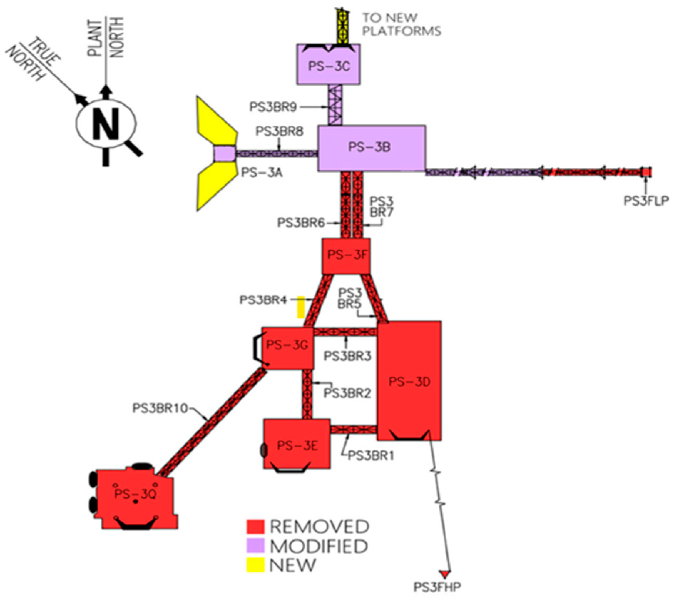
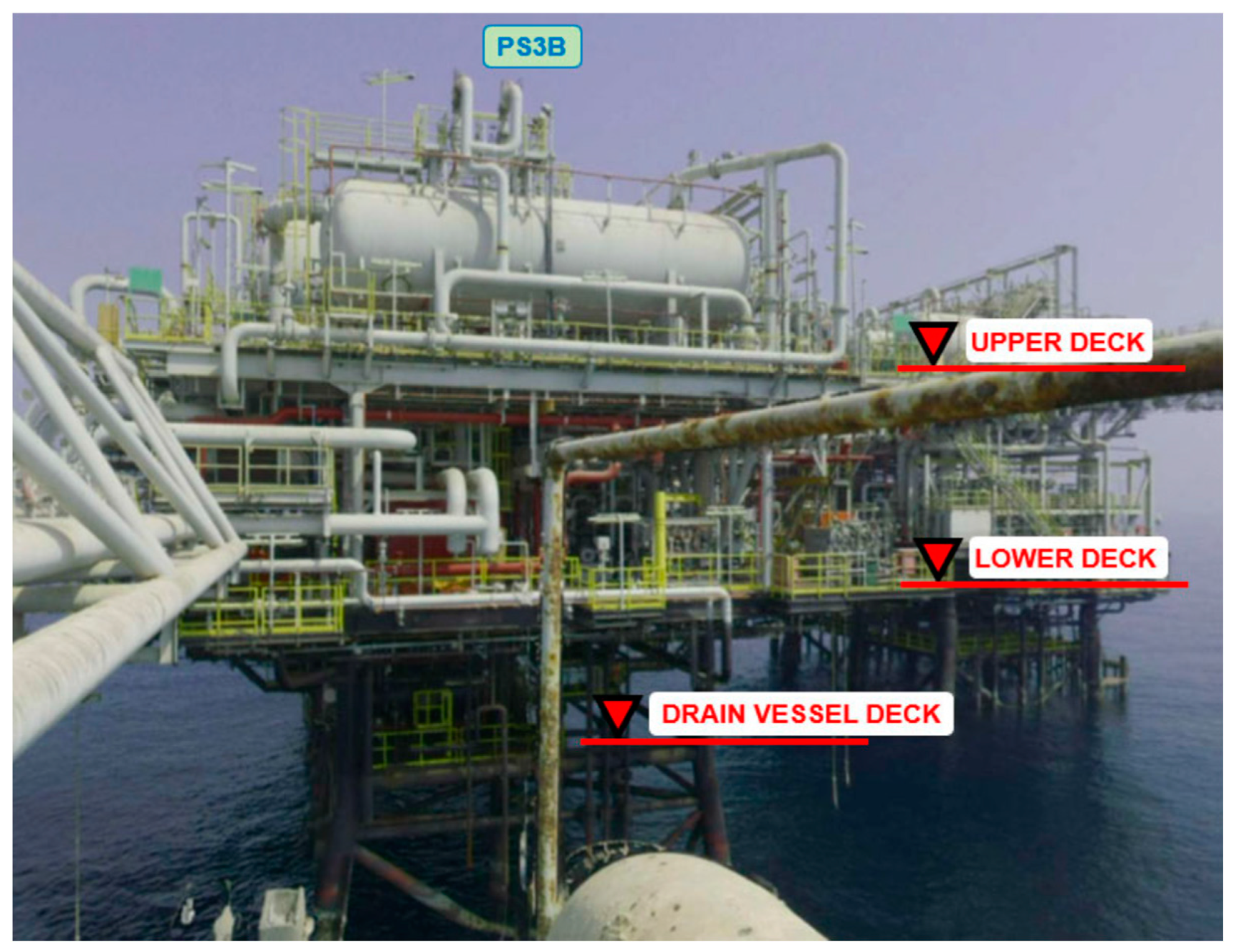
2.4. Asset Overview for PS3B Production Platform

The PS3B production platform is a three-deck topside module and jacket structure installed in 1971 comprising a drain vessel deck, a lower deck, and an upper deck. The fixed platform consists of an eight-leg piled steel jacket with raked legs. The topside module is stabbed into the jacket leg/piles transition piece. Figure 4 is a photograph of PS3B looking west, and Figure 5 is an elevation drawing looking north on the PS3B topside and jacket.

2.5. Permanent Isolation and Cleaning of Topside Facilities and Pipelines

It is important to perform draining/flushing/purging/venting on process systems, mechanical isolation of systems, bulk draining of fluids from vessels/tanks, physical isolation of systems (air gapping), and removal of potential dropped objects/loose material in modules. These activities confirm that the topside process plant status is classed as gross hydrocarbon free, preventing any possibility of re-energising, and provide a documented record of hazardous materials contained within the modules that will be transported onshore for disposal. Upon completion of the draining, flushing, purging, and venting activities, the global electrical isolation of the D&A complex can be completed. All temporary equipment required to support the PS-X3B complex decommissioning and abandonment activities is supplied from the temporary accommodation jack-up barge (JUB) through the topside preparation phases (ensuring adherence to the required performance standards during the D&A activities).

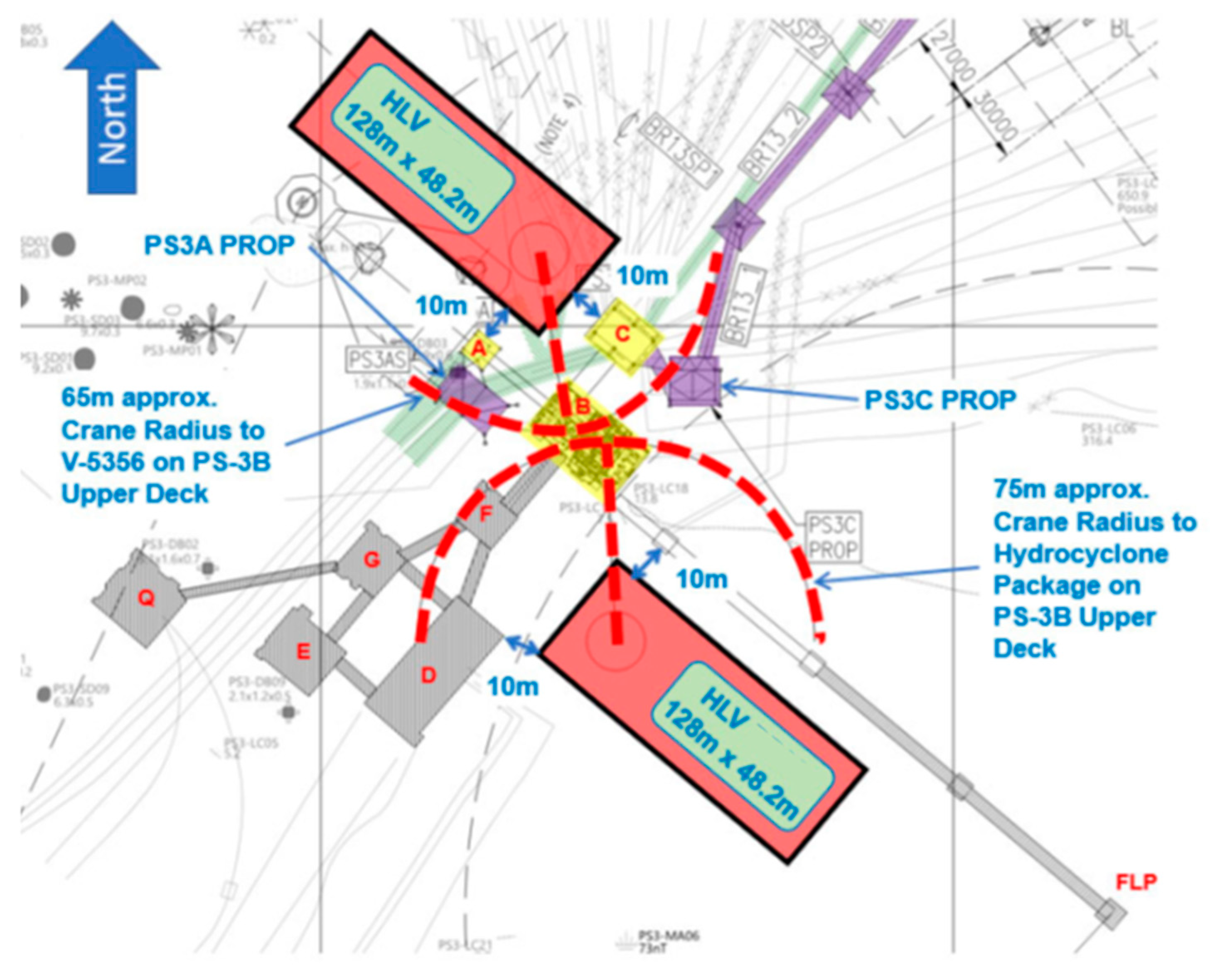
2.6. Heavy-Lift Vessel Locations

The sketch shown in Figure 6 indicates that two locations are required by a single heavy-lift vessel (HLV) to carry out the major equipment lifts.

2.7. Topside Weight Shedding

2.7.1. Weight Shedding Overview

There are three locations where weight shedding was required to destroy redundant equipment on the topsides of the PS-3B, including the upper deck, the lower deck, and the drain vessel deck. A working area was created for the decommissioning activities to achieve a target weight-shedding quantity of 750 Te. This weight is a combination of secondary/tertiary steelwork, pipework, electrical, instrumentation, and mechanical equipment that are demolished and removed. Procedures are implemented to protect primary steelwork during the works, i.e., dropped object protection, lift plans, approved method statements, risk assessments, permits to work, etc. Primary steel shall not be cut or impaired during the weight-shedding scope. The total dry weight that is to be shed across the three decks is 959.23 Te, and the total operating weight that is shed across the three decks is 1796.97 Te. For brevity, the weights of the upper and lower decks are not presented in the article.

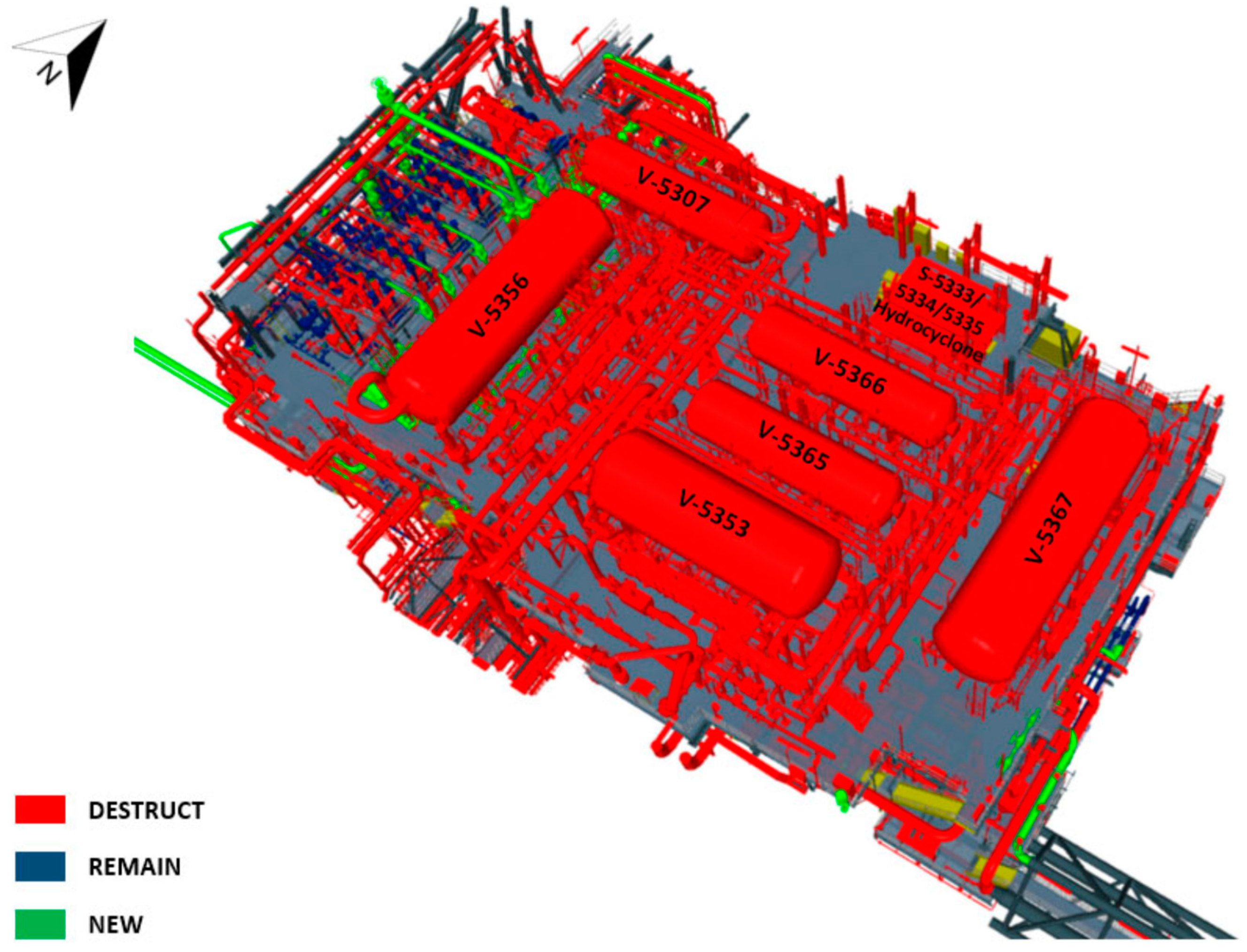
2.7.2. Upper Deck Weight Shedding

Figure 7 shows the upper deck plan, highlighting the areas of equipment to be destroyed, equipment to be retained, and new equipment to be installed on the upper deck. The total dry weight removed from the upper deck is 664.76 Te, and the total operating weight removed from the upper deck is 1281.15 Te. Figure 8 is an isometric view highlighting the areas of equipment to be demolished, equipment to be retained, and new equipment to be installed.

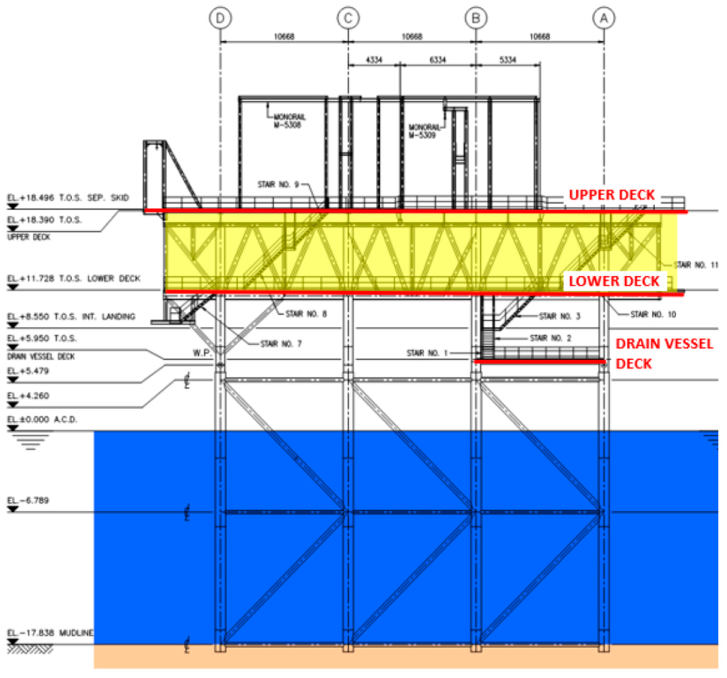
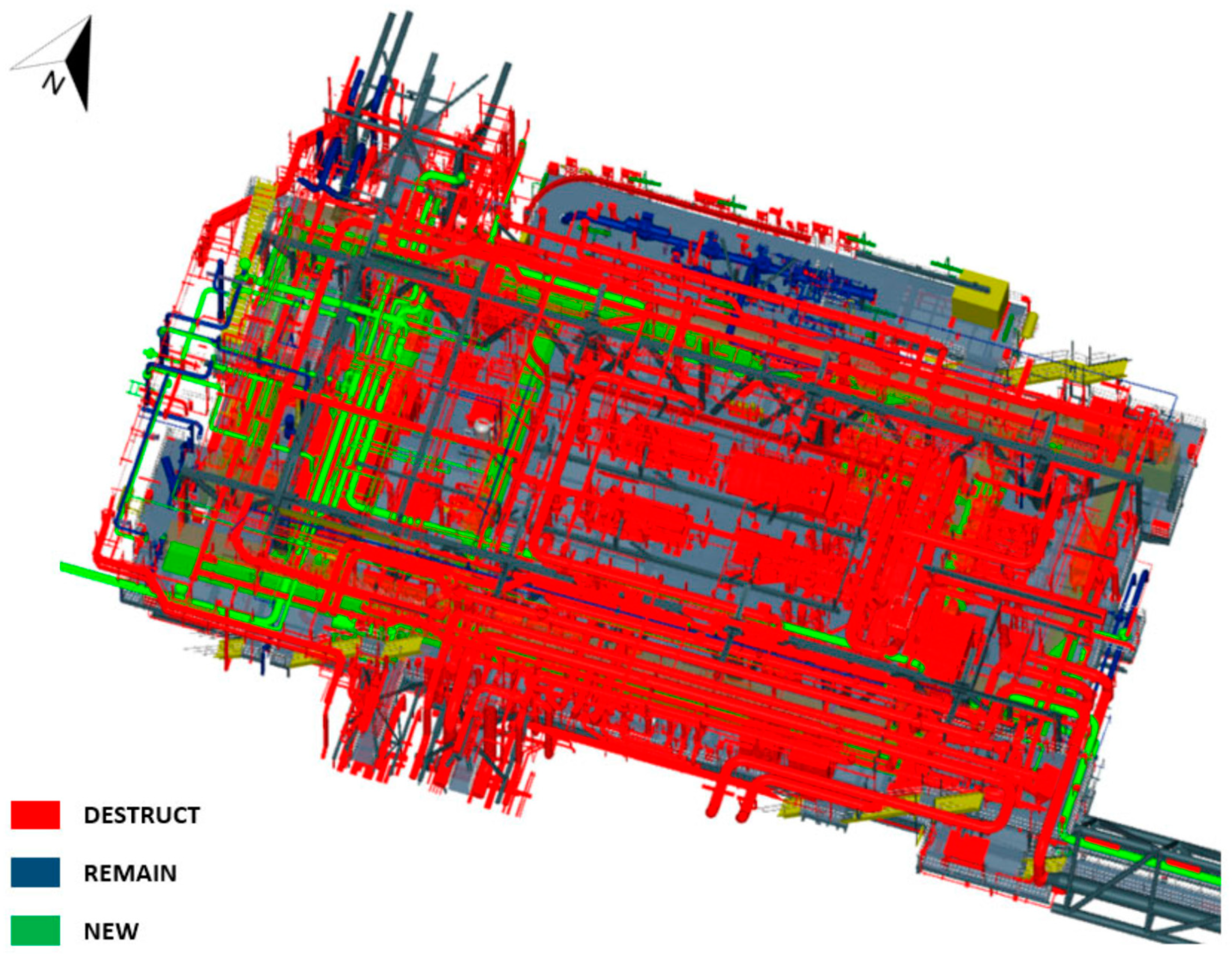
2.8. Lower Deck Weight Shedding

Figure 9 shows the lower deck plan, highlighting the areas of equipment to be demolished, equipment to be retained, and new equipment to be installed on the lower deck. The total dry weight removed from the lower deck is 255.1 Te, and the total operating weight is 462.24 Te. Figure 10 is an extract from the as-built PS-X3B elevation drawing highlighting (in yellow) the location of redundant equipment, pipework, and E&I within the lower deck between EL. +11.728 and EL. +18.390. Figure 11 is an isometric view highlighting the areas of equipment to be demolished, equipment to be retained, and new equipment to be installed. Figure 12 shows sections through the lower deck.

3. Benefits and Challenges of Weight Shedding in Decommissioning

3.1. Cost Reduction

The benefits and challenges of weight-shedding decommissioning include a significant reduction in costs. Weight shedding can result in substantial cost savings when compared to conventional decommissioning procedures since it reduces the extent and intricacy of removal operations, transportation charges, and disposal costs.

3.2. Measures to Reduce Environmental Impact

Weight shedding, through minimising the removal of material from offshore installations, effectively lowers environmental disturbance, habitat disruption, and marine pollution that are typically associated with decommissioning activities.

3.3. Resource Optimisation

This refers to the process of maximising the efficiency and effectiveness of resources used in a certain system or process. Weight shedding is a strategy that maximises resource utilisation by prioritising the removal of non-essential components, structures, and materials. This allows for the preservation of important assets and infrastructure, which can be potentially reused or repurposed.

3.4. Carbon Emissions

By minimising the construction of new platforms, it is possible to greatly reduce the carbon footprint by addressing many crucial issues. Initially, it reduces the need for primary resources such as steel, which requires a significant amount of energy to produce and has a substantial impact on carbon emissions. Furthermore, it mitigates the emissions linked to the transportation of these materials to construction sites, a process that frequently entails covering significant distances and consuming fossil fuels. Construction activities, which entail the use of substantial machinery and equipment, represent a significant contributor to emissions. By reducing the number of new projects, we can greatly reduce the amount of emissions produced on-site.
In addition, the construction process produces a significant amount of waste, a large portion of which is disposed of in landfills. This disposal contributes to additional emissions as the waste breaks down. By decreasing the amount of new construction, we concurrently decrease the quantity of waste generated. Rather than constructing new platforms, prioritising the renovation and retrofitting of existing structures can yield greater energy efficiency. Implementing improvements such as enhanced insulation, energy-efficient systems, and sustainable practices in buildings can result in reduced carbon emissions. An additional advantage of preserving natural regions is the prevention of land clearance and the subsequent release of stored carbon, as well as the preservation of ecosystems that serve as carbon sinks.
Weight shedding is more effective in reducing the carbon footprint compared to creating a completely new structure. To summarise, a reduction in new platform building leads to a drop in carbon emissions by reducing material production, minimising transportation and on-site emissions, minimising waste, improving energy efficiency, conserving natural areas, and optimising resource utilisation.

3.5. Technological Challenges

Weight-shedding decommissioning, despite its potential advantages, has technical difficulties and limitations such as structural intricacy, safety considerations, regulatory restrictions, and stakeholder concerns.

4. Future Directions of Weight Shedding in Decommissioning

4.1. Advanced Structural Analysis Techniques

Future areas of research and potential opportunities include the exploration of advanced techniques for structural analysis. Studying sophisticated methods of analysing structures, such as finite element modelling, nonlinear analysis, and probabilistic risk assessment, can improve the precision and dependability of evaluating the structural integrity for weight reduction during decommissioning.

4.2. Automation and Robotics

Progress in automation and robotics technology can simplify decommissioning operations for weight shedding, enhance safety, and decrease the need for manual labour in dangerous offshore areas.

4.3. Material Recycling and Reuse

Exploring novel methods for recycling and reusing materials can greatly enhance the sustainability of decommissioning processes by reducing waste production and encouraging concepts of a circular economy.

4.4. Policy and Regulatory Frameworks

Effective collaboration among industry players, government agencies, and regulatory authorities is crucial for developing policies and regulatory frameworks that promote the implementation of weight-shedding decommissioning concepts and ensure safety, environmental protection, and compliance.

5. Conclusions

This study presents an innovative method for decommissioning offshore facilities by reducing their weight. The goal is to lower costs, minimise environmental effects, and optimise the use of resources. Weight shedding presents a favourable method for decommissioning offshore installations, which can effectively lower expenses, minimise environmental consequences, and optimise the use of resources. Weight shedding is a planned process of removing unnecessary components and structures, which helps to reduce the scope and complexity of decommissioning activities. At the same time, it allows important assets to be preserved for eventual reuse or repurposing. Despite the presence of obstacles and restrictions, continuous research and innovation in weight-reduction decommissioning concepts can revolutionise the offshore business and encourage environmentally friendly decommissioning techniques. The concept entails systematically eliminating superfluous components and structures to decrease the overall weight of the facility before its final decommissioning. Based on the operational requirements of decommissioning, the following activities are recommended to be completed before weight shedding is commenced on any offshore platform:
  • Installation and commissioning of temporary equipment (power, air, light, etc.) that meets the appropriate performance standards for the decommissioning and abandonment plan.
  • Draining, flushing, purging, and venting of the hydrocarbon process system.
  • Processing boundary isolations wherever installed.
  • Engineering down and cleaning all systems on the offshore platform.
  • Providing global electrical isolations on the platform and switching over to temporary systems.
  • Completing the pre-commissioning of greenfield facilities.
During the reassessment of existing offshore platforms, the long-term soil ageing may be considered to provide an even greater increase in foundation strength. If this is necessary for confirmatory reassessments, a restrike test is required in the field. This would have to be a new pile installed sufficiently deep, and the restrike test would have to be performed after a sufficiently long stop-and-go duration.

Author Contributions

Conceptualization, A.R., C.V.A., M.A.S. and K.K.M.; methodology, A.R., C.V.A., M.A.S. and K.K.M.; formal analysis, A.R., C.V.A., M.A.S., and K.K.M.; investigation, A.R., C.V.A., M.A.S. and K.K.M.; resources, A.R., C.V.A., M.A.S. and K.K.M.; writing—original draft preparation, A.R., C.V.A., M.A.S. and K.K.M.; writing—reviewing draft, A.R., C.V.A., M.A.S. and K.K.M.; data curation, A.R., C.V.A., M.A.S. and K.K.M.; visualization, A.R., C.V.A., M.A.S. and K.K.M.; supervision, A.R., C.V.A., M.A.S. and K.K.M.; project administration, A.R., C.V.A., M.A.S. and K.K.M. All authors have read and agreed to the published version of the manuscript.

Funding

This research received no external funding.

Informed Consent Statement

All authors have read and agreed to the published version of the manuscript.

Data Availability Statement

The data are not publicly available due to privacy.

Conflicts of Interest

The authors declare no conflict of interest. The funders had no role in the design of the study; in the collection, analysis, or interpretation of data; in the writing of the manuscript, or in the decision to publish the results.

Appendix A. Decommissioning and Abandonment

Given the authors’ opinion, the strategy of any decommissioning and abandonment (D&A) can be summarised by the following main work areas:
  • Engineer down and clean/make safe.
  • Risk and opportunity management.
  • Topside preparation/weight shedding.
  • Topside and jacket removal.
  • Onshore disposal.
  • Environmental management.
The outputs from these work areas produce technical deliverables that support the cost estimate and schedule, and align with the master deliverable register contents, all of which together support the preparation of the contractual packages.

Appendix A.1. Engineer Down and Clean/Make Safe

This generally refers to engineering down, cleaning, and removal of hydrocarbons, and isolation of all relevant energy sources. As part of the decommissioning activities, it is important to assess each platform and pipeline to be removed (or abandoned in situ, as the case may be). It is vital to apply a logical methodology when reviewing how to isolate and clean, considering the specifics of the asset. This step aims to ensure that the assets are left as ‘dumb steel’ and that the risk of harm to personnel and the environment is as low as reasonably practicable (ALARP). During the selection of the decommissioning concept, the following requirements of ALARP will be considered:
  • Identify health, safety, security, and environmental (HSSE) hazards and document their effects on people, assets, environment, and reputation in a hazards and effects register.
  • Assess the risk of identified hazards for worst-case credible scenarios using the risk assessment matrix (RAM).
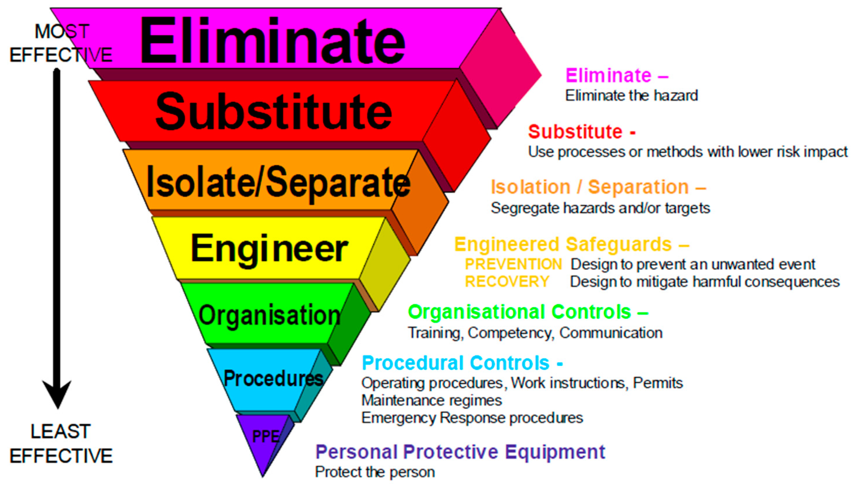
  • Apply the hierarchy of controls for managing risk (see Figure A1).
  • Where reasonably practicable, eliminate hazards or substitute hazards with ones having lower risk.
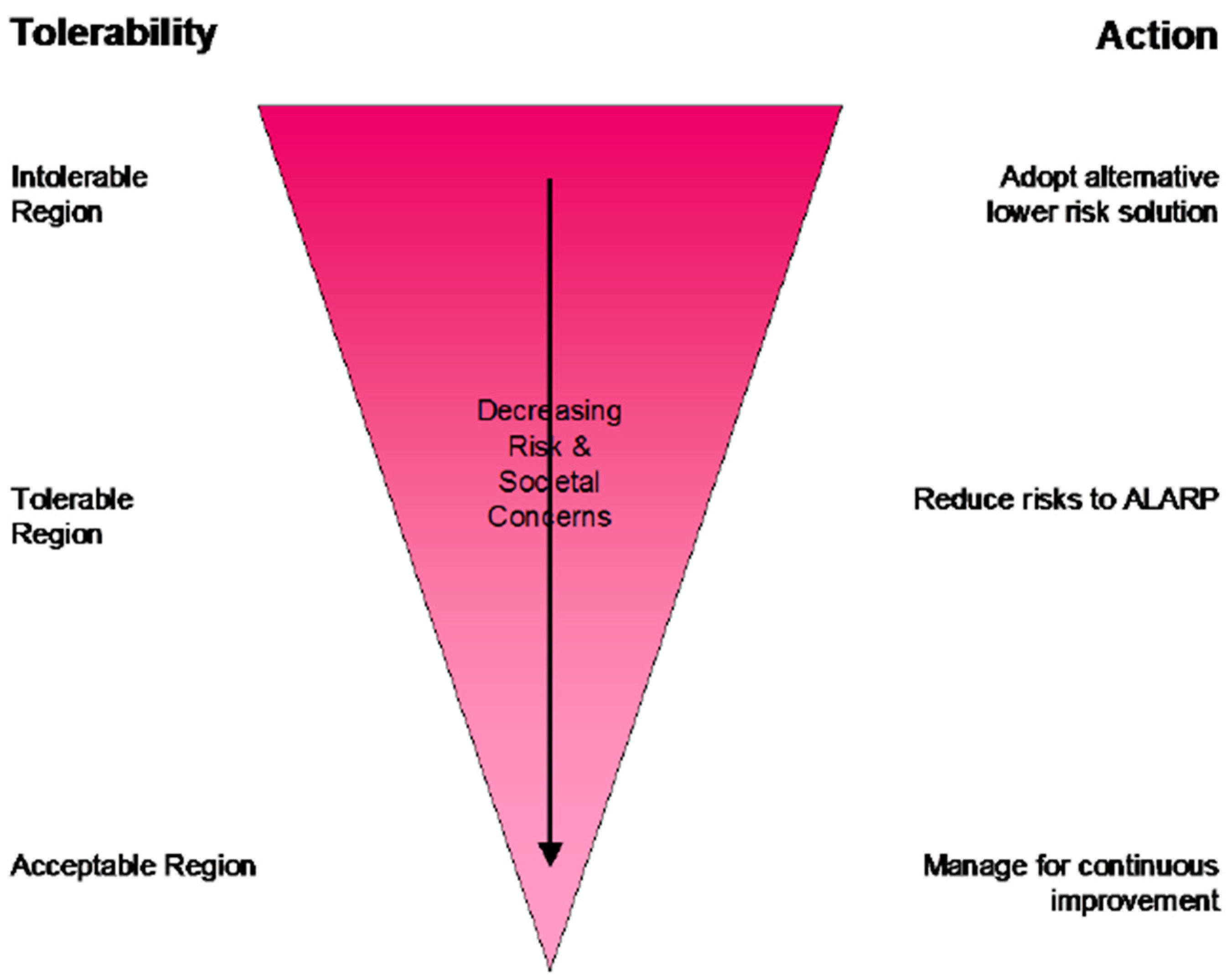
  • Identify and implement control and recovery measures to reduce risks to ALARP.
  • Actively seek out and, where reasonably practicable, select the lowest risk options.
Figure A1. Hierarchy of controls for managing risk.
Jmse 12 01331 g0a1
During this process, inventories and potential reuse/disposal options shall be created, and deliverables aligned with the requirements of the local regulations for abandonment of fixed offshore installations (topsides and jackets). The details of how the equipment and fluids are dealt with onshore should be captured in waste disposal studies.

Appendix A.2. Risk and Opportunity Management

The procedures for risk management, including risk identification and quantitative risk assessment (QRA), are aligned with the project execution plan (PEP) and project quality management plan and utilise the standards set out as part of the project. The decommissioning and abandonment scope should contribute to the overall project risk register where appropriate. Mitigation plans are developed as required, and actions are captured following the project risk management plan. Sufficient engineering studies should be conducted throughout the project as a basis on which to establish a safe design so that any hazards that could affect personnel safety, environment, assets, and the operator’s reputation are identified, evaluated, and appropriate measures are taken to prevent, control, or mitigate their occurrence and to reduce risk to ALARP.
The principle of ALARP (refer to Figure A2) is that HSSE risks shall be demonstrated to be both tolerable (within all legislative and other company and project requirements), and also further reduced as far as reasonably practicable. To reduce risk to a level which is ALARP involves balancing reduction in risk against the time, trouble, difficulty, and cost of achieving it. This level presents the point, objectively assessed, at which the time, trouble, difficulty, and cost of further reduction measures become grossly disproportionate to the additional risk reduction achieved. In the ALARP region, risk reduction measures (design options, additional or better barriers) should be sought until the cost and effort to implement these measures are grossly disproportionate to the risk reduction. When that point is reached, the risks have been reduced to ALARP. The risks should then be managed for continuous improvement.
Figure A2. ALARP triangle.
Jmse 12 01331 g0a2
A generic framework developed for the UK Offshore Operators Association [32] by an industry workgroup can be adopted during ALARP. This framework assists in guiding and supporting the decision-making process for the implementation of safety recommendations or issues.

Appendix A.3. Topside Preparation/Weight Shedding

In this study, weight shedding refers to the specific activity of removing infrastructure, equipment, and pipework from platforms which are not planned to be fully removed but must have their weight reduced to facilitate new additions. Weight shedding must be managed with a brownfield modification philosophy when compared to complete asset removal, as the asset will revert to producing status.

Appendix A.4. Topside and Jacket Removal

Work conducted under this sub-area refers to preparation for removal, assessing the structural work required for lifting, and the most appropriate methodology for removal. Due to the age of the assets, the integrity of lifting points and weight control over the history of production are considered when engineering the removal strategy and preparing the master deliverable list for the decommissioning scope.

Appendix A.5. Onshore Disposal

Onshore facilities for disposal and recycling shall be of a suitable standard to accommodate offshore structures. The quayside needs to be large enough for offloading the cargo barges and strong enough to sustain the load of the structures. It is common practice to offload the structure from the barges to the quayside by placing them on self-propelled modular transporters (SPMTs) and relocating them to designated dismantling areas of the yard. Smaller items can be removed using crawler cranes. Modules used for hydrocarbon production are placed within an appropriate area of the facility served by open hazardous drains to contain any spillage. The onshore facility itself shall be of adequate size to accept the structures and be equipped with the required machinery for dismantling. Module dismantling involves removing and properly disposing of asbestos, naturally occurring radioactive material (NORM), mercury, polychlorinated biphenyl (PCB), and other hazardous materials via licensed disposal routes. This is followed by the stripping of valuable materials like copper, rare earth metals, waste electrical and electronic equipment, the removal of soft furnishings for appropriate recycling, and then finally the steel structure is demolished in a controlled manner for recycling.

Appendix A.6. Environmental Management

For all decommissioning and abandonment activities, effective removal methodologies shall be designed to meet or exceed legislative requirements and be compliant with ISO 14001 [33] standards, any local requirements, and the approved Environmental Impact Assessment (EIA) and Environment Management Plan. In addition to local regulations, the decommissioning practices for offshore installations shall be based on IMO Resolution A.672 [34], which applies to all marine areas except for the North East Atlantic regions where the OSPAR Convention [35] is in force. It should not be necessary to repeat information that is presented elsewhere in the decommissioning programme, but an assessment of the potential effects of the project on the environment must be undertaken, and the measures envisaged to avoid, reduce, and, if possible, remedy any significant adverse effects indicated. The EIA should include the following [36,37,38]:
  • All potential impacts on the marine environment, including exposure of biota to contaminants associated with the installation, other biological impacts arising from physical effects, conflicts with the conservation of species, with the protection of their habitats, or with mariculture, and interference with other legitimate uses of the sea.
  • All potential impacts on other environmental compartments, including emissions to the atmosphere, leaching to groundwater, discharges to surface fresh water, and effects on the soil.
  • Consumption of natural resources and energy associated with reuse and recycling.
  • Other consequential effects on the physical environment which may be expected to result from the option.
  • Potential impacts on amenities, the activities of communities, and future uses of the environment.

Appendix B. Decommissioning Breakdown

Appendix B.1. Project Management

The project execution plan sets out the overall project management approach to the D&A execution plan and further details relevant additions specific to the decommissioning scope. The D&A scope is managed following the applicable local regulations, standards, and guidelines [39,40,41].

Appendix B.2. Post-CoP Running Costs

Post cessation of production (CoP) running costs refer to operational expenditure after termination of production on a platform but does not mean that all activity on the platform has stopped—all major mazards must be removed to ALARP, such as isolation of wells and removal of hydrocarbons [42,43,44]. This work breakdown structure is considered completed once the topsides are removed. Costs which are included may be onshore and offshore support teams, diesel and other fuels, integrity management, inspection and maintenance activities, and other costs associated with the routine management of the assets such as power, water, logistics, and accommodation costs. The requirement for any idle phase should be fully assessed during the early stage of any project and if it is selected, running costs during the period post-CoP will vary depending primarily on the duration of any lighthouse mode (referred to as idle phase). In the initial period post-CoP, there would be platform visits required to manage the safety and environmentally critical elements required to be maintained, such as navigation lighting, platform evacuation equipment (life rafts, etc.), and any life support systems and necessary utilities. As the time from CoP increases, deterioration in the asset’s physical conditions also increases, and additional consideration needs to be factored into operating expenditure (OPEX) running costs. The risk to structural integrity also increases as the time from CoP extends, leading to an additional risk assessment being required in advance of any scheduled or unscheduled maintenance visits.

Appendix B.3. Well Decommissioning

The well decommissioning does not form part of this article. For reference, in the OEUK guidelines, it is defined as the permanent isolation of any rock formations with flow potential and the restoration of the seabed to its previous status, with three phases [41,42,43,44,45,46]:
  • Permanent isolation of the reservoir.
  • Permanent isolation of any intermediate zones with flow potential. This phase is considered complete when all required barriers are in place.
  • A well is considered fully decommissioned after removing the wellhead and conductor, the well origin at the surface is removed, and the well will never be reused or entered again.

Appendix B.4. Permanent Isolation and Cleaning of Facilities and Pipelines

The platform and pipelines used to recover and transport the hydrocarbons must be isolated and cleaned. This involves ensuring any pressure sources are neutralised and that the installation is free, as far as is reasonably practicable, of hydrocarbons and contaminants. MAKE SAFE of the topsides is typically executed on a system-by-system basis and involves activities including shutdown, draining, flushing, purging, and venting of hydrocarbon and utility systems, mechanical and electrical isolation, removing any residual hydrocarbon sludges, disposal of hazardous wastes, and flushing of pipelines. Offshore operations personnel are responsible for shutting down and isolating post-gas/hydrocarbon freeing for handover to the contractor. The offshore MAKE SAFE scope of work shall be kept to a minimum whilst ensuring that the platforms are suitably prepared for safe transport to shore for further dismantling and cleaning. Any systems that can be permanently isolated before an overall facility shutdown would reduce the activities required to be carried out post-shutdown, therefore minimising the shutdown period. MAKE SAFE will ensure that the project maximises onshore destruction, cleaning, and decontamination of modules while also ensuring the following items:
  • Protection of personnel from exposure to hazardous wastes.
  • Protection of the environment from uncontrolled discharges.
  • Minimising fuel sources which could pose fire and explosion hazards.
  • Allowing reclassification of hazardous areas as and when flammable hazards are permanently removed.
  • Facilitating future preparation for the removal of the topsides, transportation, and disposal. The required cleaning work not only includes the removal of hydrocarbons and other hazardous fluids but also considers hazardous materials such as asbestos and radioactive substances such as those found in nucleonic level detection instruments.
MAKE SAFE scopes are interconnected as process, utility, and electrical systems pass through several common modules, including the bridges, which shall be considered separate modules for the decommissioning project. Positive isolations fall into two high-level categories: process (i.e., piping) isolation and E&I isolation. Process isolation begins with designing, identifying, and implementing boundary/system isolations. This isolation shall be controlled and documented. The design of the isolations shall make use of large global boundary perimeters to minimise isolation requirements and allow less restricted working inside the boundary isolations. Following the implementation of boundary isolations, further positive isolations are applied to ensure decommissioned systems and/or equipment are ‘permanently’ disconnected from potential sources of energy and/or hazardous inventories. This involves breaking containment, removal of spools, installation of blind flanges, local venting and draining, etc. The proposed means for achieving positive isolations are usually developed by the D&A team before the execution.

Appendix B.5. Temporary Utility and Life Support Systems

During decommissioning activities, in certain scenarios, there may be a requirement to install temporary facilities to enable decommissioning activities. The temporary systems/equipment to be considered include:
  • Power generation system.
  • Power distribution system.
  • Diesel fuel storage and distribution system.
  • Air compressor and distribution system.
  • Seawater supply and distribution system for flushing.
  • Instrument and telecommunication facilities.
An important area to address is the control rooms on existing D&A platforms to ensure there are control arrangements made for the instrument and telecommunication facilities that are not demolished to maintain control during the D&A activities. Typically, these temporary systems are installed in parallel to the existing systems and enable the engineering down and isolation of some of the existing systems as required. Until the relevant asset has achieved ‘hydrocarbon free’ status, temporary equipment must be suitable for the hazardous zone classification in which it is operating. Consideration can be given to renewable energy power systems which are becoming more common in lighthouse mode/idle phase operations, contributing to reducing both OPEX costs and carbon emissions.

Appendix B.6. Preparation for Idle Phase

Once the redundant sections of the production stations have gone through the MAKE SAFE process, removing bulk hydrocarbons to ALARP, there may be a delay in the arrival of the removal contractor and subsequent dismantlement/removal stage. During this time, there should be no requirement for personnel to visit the platform save for any preparatory works for the removal. During the idle phase, structures, including bridges, must be retained in a structurally sound state, and any cutting and separation completed in this phase must be stable with sufficient strength to withstand weather, seismic, and accidental loads such as ship collisions. During the engineering stage, the D&A team should consider the benefits and risks of maintaining such assets and the associated cost against promoting earlier removal. The initial basis considers the full removal of all assets following the start-up of the greenfield development; however, external factors influence this, such as vessel availability, weather conditions, and waste disposal sites (if they have sufficient capacity to dispose of several platforms at once).

Appendix B.7. Disconnection—Preparation for Removal

In advance of the platform being removed, work can commence to physically separate modules and packages in preparation for removal by HLV. The work involved is dependent on the removal method selected (i.e., reverse installation or piecemeal approach), which should be determined during the engineering stage but will likely include the following:
  • Structural separation: temporary and secondary steelwork (e.g., walkways, stairs, seal welds, etc.).
  • Piping separation: process and utility pipework and supports.
  • Electrical and instrument separation: power, instrument and control cables, cable trays, light fittings, etc.
  • Heating, ventilation, air conditioning (HVAC) separation: vent ducts.
  • Caissons, risers and J-tube separation.

Appendix B.8. Topside Removal

Redundant equipment and structures of the topsides shall be removed. As part of the engineering stage, removal options of the topsides for the production stations should be investigated. A summary of each option and potential advantages and disadvantages are detailed in Table A1.
Table A1. Comparison of removal options for topsides.
OptionDescriptionAdvantagesDisadvantages
Reverse Installation/Individual Module RemovalMost of the PS topsides were installed in individual modules.Lower chance of having to strengthen modules as the modules were designed for this lifting method.A large amount of offshore separation work.
Singe LiftDue to the increase in capacity of offshore HLVs, it may be possible to lift more than one of the modules at any one time.Fewer offshore lifts; less separation to be undertaken offshore.Strengthening of modules may be required, especially at lifting points, due to greater weight to be removed.
Piecemeal RemovalThe topsides would be broken down offshore and loaded onto barges using the HLV cranes. An analysis of the order of removal would be performed in the planning for the decommissioning phase.HLV is only needed for the very last stage. A large proportion of work will be able to be completed using a platform crane (if available).More offshore separation works, therefore greater offshore programme. Analysis will be required to determine the stability of cranes throughout demolition works.

Appendix B.9. Substructure Removal

The jackets need to be completely removed, and any piles should be severed below the natural seabed level at such a depth to ensure that any remains are unlikely to become uncovered. The depth will depend upon the prevailing seabed conditions and currents, as well as regulatory requirements. For instance, jacket piles in the UK are required to be cut 3 m below the seabed (UK Decommissioning Guidelines). The jacket removal options for all removal candidate platforms should be investigated. A summary of each option is listed in Table A2.
Table A2. Substructure removal summary.
OptionDescriptionAdvantagesDisadvantages
Jacket piecemeal removal.Jackets, footings, and piles would be cut into small manageable pieces and lifted to the surface to be transported to shore.Lift weights are lower, so greater competition of HLV. Easier to offload at the disposal yard, especially if barge-loaded.Many underwater cuts at great depth; environmental, programme, and cost issues. A large number of lifts.
The jacket is removed in a single lift by HLV.Piles are excavated and cut at a level agreed with the regulator. Jacket lifted by HLV to a barge or transported to shore in the hook.A small number of underwater cuts are required. Reduced offshore programme. If there is sufficient crane height, the jacket upending can be avoided, simplifying the lift. If readily available HLV capacity is exceeded, the option to remove in two sections may be more economical than a larger capacity vessel.
Each removal option is investigated for the jacket; the areas that are addressed include but are not limited to the extent of cutting, availability of technology required for removal, and potential structural strengthening required. Each of the jackets is secured in place by through-leg piles. To allow the removal of the jacket, the piles need to be cut below the mud line. The method for cutting the piles will be assessed during the jacket removal studies.

Appendix B.10. Onshore Disposal

The receiving facility (or facilities) for the topsides and jackets must be identified as early as possible [46,47,48,49]. This then informs the waste disposal strategy and provides detailed input into the cost and schedule deliverables. Waste hierarchy is a conceptual framework which ranks the options for dealing with waste in terms of their sustainability and will underpin the execution strategy. Depending on the approach selected, the decommissioning programme may indicate how the principles of the waste hierarchy can be met and show the extent to which the installations, including topsides and materials contained within the installations, can be reused, recycled, or disposed of on land. Figure A3 shows a typical waste hierarchy. The waste hierarchy principles shall be embedded within the waste management report to be developed, which reflects the different elements of the work:
  • Offshore operations.
  • Topside and jacket disposal.
  • Subsea infrastructure.
  • Flushed process fluids containing hazardous materials.
Given the age and condition of the equipment and structures for the production stations, it is very unlikely that there would be any items suitable for reuse, and all items are more likely to have at best scrap value. Field instruments, fire and gas devices, control and safety systems, and panels will also be assessed for alternative reuse (i.e., scrap or reuse). The subsea infrastructure is likely to be in a similar situation with significant integrity issues if the equipment is even recovered.
Figure A3. Typical waste hierarchy.
Jmse 12 01331 g0a3
The handling and disposal options for each of the waste streams are assessed against the waste hierarchy, ensuring options for reuse and recycling wherever possible in preference to being disposed of. The types of waste generated include but are not limited to the following: steel, glass, wood, plastics, composite materials, metals (e.g., lead, zinc, aluminium, anodes), concrete, electrical equipment and cabling, liquid washings and sludges, and marine growth.
Options for recycling or disposal may be dependent on the presence of hazardous contaminants associated with the construction materials used and activities previously carried out on the platforms. These include but are not limited to the following: hydrocarbons, hydrogen sulphide, benzene, production chemicals, asbestos, paint, naturally occurring radioactive material, heavy metals, radioactive isotopes, polychlorinated biphenyls, and pyrophoric scale.
All waste materials generated in the process of decommissioning the production stations shall be treated or disposed of by licensed contractors at licensed sites with all the necessary permits and consents. The disposal phase of the project may involve further cleaning, separation, and disposal of the removed and transported sections of the platform topsides and jacket structures. To ensure an effective, cost-efficient, and environmentally sustainable disposal of the platform, an assessment of the capabilities of disposal yards within the accessible area of the platform shall be carried out. This assessment reviews all the technical aspects of the disposal, including but not limited to the following:
  • Distance of disposal yard from the platform.
  • Accessibility of the yard from the sea.
  • Offloading and heavy-lift capabilities.
  • Laydown area/yard space.
  • Security arrangements.
  • Watertight floored space/covered storage capacity.
  • HSSE management plans.
  • Waste management systems.
  • Material control procedures.
To ensure material is reused and recycled wherever possible in preference to being disposed of, the waste hierarchy shall be implemented when considering the disposal options. During the planning and removal phases, it is important to liaise with the disposal yard and ensure that sea fastenings are designed to facilitate offload from the barge, thus ensuring a smooth transition from the offshore facility into the disposal yard. The methods for landing the structures on the quayside vary and include the use of HLV crane vessels, yard cranes, or occasionally multi-wheelers. Procurement decisions may result in some of the platform and its facilities being delivered overseas for onshore disposal. Relevant regulations on the trans-frontier shipment of waste would apply to all waste disposed of overseas.

References

  1. Bull, A.S.; Love, M.S. Worldwide oil and gas platform decommissioning: A review of practices and reefing options. Ocean Coast. Manag. 2018, 168, 274–306. [Google Scholar] [CrossRef]
  2. Elchalakani, M.; Kimiaei, M.; Reda, A.; Yang, B. Repair and strengthening of offshore platforms topside girders using externally bonded fibre-reinforced polymers. Ocean. Eng. 2023, 272, 113313. [Google Scholar] [CrossRef]
  3. Amaechi, C.V.; Reda, A.; Butler, H.O.; Ja’e, I.A.; An, C. Review on fixed and floating offshore structures. Part I: Types of platforms with some applications. J. Mar. Sci. Eng. 2022, 10, 1074. [Google Scholar] [CrossRef]
  4. Amaechi, C.V.; Reda, A.; Butler, H.O.; Ja’e, I.A.; An, C. Review on fixed and floating offshore structures. Part II: Sustainable design approaches and project management. J. Mar. Sci. Eng. 2022, 10, 973. [Google Scholar] [CrossRef]
  5. Wilkinson, W.B.; Bakke, T.; Clauss, G.F.; Clements, R.; Dover, W.D.; Rullkötter, J.; Shepherd, J.G. Decommissioning of large offshore structures—The role of an Independent Review Group (IRG). Ocean. Eng. 2016, 113, 11–17. [Google Scholar] [CrossRef]
  6. Pollett, B.B. Risk-Based Offshore Decommissioning Standards and Regulations. In Proceedings of the Offshore Technology Conference, Houston, TX, USA, 4–7 May 2020. [Google Scholar] [CrossRef]
  7. Techera, E.J.; Chandler, J. Offshore installations, decommissioning and artificial reefs: Do current legal frameworks best serve the marine environment? Mar. Policy 2015, 59, 53–60. [Google Scholar] [CrossRef]
  8. Smyth, K.; Christie, N.; Burdon, D.; Atkins, J.P.; Barnes, R.; Elliott, M. Renewables-to-reefs?—Decommissioning options for the offshore wind power industry. Mar. Pollut. Bull. 2015, 90, 247–258. [Google Scholar] [CrossRef] [PubMed]
  9. Chandler, J.; White, D.; Techera, E.J.; Gourvenec, S.; Draper, S. Engineering and legal considerations for decommissioning of offshore oil and gas infrastructure in Australia. Ocean. Eng. 2017, 131, 338–347. [Google Scholar] [CrossRef]
  10. Hall, R.; Topham, E.; João, E. Environmental Impact Assessment for the decommissioning of offshore wind farms. Renew. Sustain. Energy Rev. 2022, 165, 112580. [Google Scholar] [CrossRef]
  11. Gorman, D.G.; Neilson, J. Decommissioning Offshore Structures; Series Title: Environmental Science and Engineering; Springer: London, UK, 1998. [Google Scholar] [CrossRef]
  12. Shams, S.; Prasad, D.R.; Imteaz, M.A.; Khan MM, H.; Ahsan, A.; Karim, M.R. An Assessment of Environmental Impact on Offshore Decommissioning of Oil and Gas Pipelines. Environments 2023, 10, 104. [Google Scholar] [CrossRef]
  13. Junior FJ, C.; Bressan RD, S.; Nicolosi, E.R.; Santana AL, B.; De Souza, D.C.; Fernandes, P.T.; Tavares, G.M. Cost Reduction Challenges in Subsea Decommissioning Operations. In Proceedings of the Offshore Technology Conference, Houston, TX, USA, 1–4 May 2023; p. D031S039R001. [Google Scholar] [CrossRef]
  14. Bressan, R.S.; Artigas, D. Task Scheduling for Subsea Flexible Pipes Decommissioning. In Proceedings of the Offshore Technology Conference, Houston, TX, USA, 16–19 August 2021. [Google Scholar] [CrossRef]
  15. Reda, A.; Amaechi, C.V.; Diaz Jimenez, L.F.; Sultan, I.A.; Rawlinson, A. Guideline for the Decommissioning/Abandonment of Subsea Pipelines. J. Mar. Sci. Eng. 2024, 12, 8. [Google Scholar] [CrossRef]
  16. Reda, A.; Amaechi, C.V.; Shahin, M.A. Case study for effects of pile installation on existing offshore facilities in brownfields. Appl. Ocean. Res. 2023, 138, 103651. [Google Scholar] [CrossRef]
  17. Kaiser, M.J. A review of onshore and offshore pipeline construction and decommissioning cost in the USA-part 1: Specifications, cost estimation and onshore construction. Int. J. Oil Gas Coal Technol. 2021, 27, 247–285. [Google Scholar] [CrossRef]
  18. Kaiser, M.J. BSEE decommissioning cost estimates in the shallow water US Gulf of Mexico. Ships Offshore Struct. 2023, 18, 1482–1496. [Google Scholar] [CrossRef]
  19. Bijker, R.; Chen, Z. Prediction model for decommissioned offshore pipelines. In Proceedings of the ISOPE International Ocean and Polar Engineering Conference, Stavanger, Norway, 17–22 June 2001; p. ISOPE-I. [Google Scholar]
  20. Jas, E.; Selman, A.; Linton, V. Out of sight out of mind–subsea pipeline decommissioning. APPEA J. 2017, 57, 79–87. [Google Scholar] [CrossRef]
  21. Shen, Y.; Birkinshaw, P.; Palmer-Jones, R. Challenges in offshore pipeline decommissioning and what can we learn from integrity management practices. In Proceedings of the ISOPE International Ocean and Polar Engineering Conference, San Francisco, CA, USA, 25–30 June 2017; p. ISOPE-I. [Google Scholar]
  22. Koroma, S.G.; Animah, I.; Shafiee, M.; Tee, K.F. Decommissioning of deep and ultra-deepwater oil and gas pipelines: Issues and challenges. Int. J. Oil Gas Coal Technol. 2019, 22, 470–487. [Google Scholar] [CrossRef]
  23. Raitt, P.; Selman, A.; Lanoëlle, C. Engineering and environmental studies for decommissioning of subsea infrastructure. APPEA J. 2019, 59, 277–288. [Google Scholar] [CrossRef]
  24. Anderson, J.M. Decommissioning pipelines and subsea equipment: Legislative issues and decommissioning processes. Underw. Technol. 2002, 25, 105–111. [Google Scholar] [CrossRef]
  25. Tularak, A.; Ali Khan, W.; Thungsuntonkhun, W. Decommissioning challenges in Thailand. In Proceedings of the SPE Asia Pacific Health, Safety, Security, Environment and Social Responsibility Symposium, Bangkok, Thailand, 10–12 September 2007; p. SPE-108867. [Google Scholar]
  26. Greca, A.D. Decommissioning & removal options: Which choice? In Proceedings of the ISOPE International Ocean and Polar Engineering Conference, Los Angeles, CA, USA, 26–31 May 1996; p. ISOPE-I. [Google Scholar]
  27. MacKenzie, H.; Jones, C. Cost Reducing Pipeline Decommissioning Technology. In Proceedings of the SPE Offshore Europe Conference and Exhibition, Aberdeen, UK, 8–11 September 2015; p. SPE-175487. [Google Scholar]
  28. Smith, R.W. An Assessment of Current US Pipeline Flushing Practice and Decommissioning Requirements: How Clean Is Clean? In Proceedings of the International Conference on Offshore Mechanics and Arctic Engineering, Oslo, Norway, 23–28 June 2022; Volume 36142, pp. 33–38. [Google Scholar]
  29. Yap, T.L. Planning & Execution of Field 1 Subsea Facilities Decommissioning. In Proceedings of the SPE Symposium: Decommissioning and Abandonment, Kuala Lumpur, Malaysia, 3–4 December 2018; p. D011S004R002. [Google Scholar]
  30. Krause, P.; Baquiran, J. Determining Environmentally Superior Decommissioning Options for Hard and Flexible Pipelines. In Proceedings of the SPE Symposium: Decommissioning and Abandonment, Kuala Lumpur, Malaysia, 3–4 December 2019; p. D011S002R003. [Google Scholar]
  31. Philip, N.S.; Wilde, S.; Arshad, R.; Washash, I.; Al-Sayed, T.A. Decommissioning process for subsea pipelines. In Proceedings of the Abu Dhabi International Petroleum Exhibition and Conference, Abu Dhabi, United Arab Emirates, 10–13 November 2014; p. D021S035R005. [Google Scholar]
  32. UKOOA. Industry Guidelines on a Framework for Risk Related Decision Making; UK Offshore Operators Association: Aberdeen, UK, 1999. [Google Scholar]
  33. ISO 14001:2015; Environmental Management Systems—Requirements with Guidance for Use. ISO: Geneva, Switzerland, 2015. Available online: https://www.iso.org/standard/60857.html (accessed on 1 June 2024).
  34. IMO Resolution A.672 (16) Guidelines and Standards for the Removal of Offshore Installations and Structures on the Continental Shelf and in the Exclusive Economic Zone. Adopted on 19 October 1989. Available online: https://wwwcdn.imo.org/localresources/en/KnowledgeCentre/IndexofIMOResolutions/AssemblyDocuments/A.672(16).pdf (accessed on 1 June 2024).
  35. OSPAR Commission. OSPAR Convention. In Convention for the Protection of the Marine Environment of the North-East Atlantic; Text as Amended on 24 July 1998, Updated 9 May 2002, 7 February 2005 and 18 May 2006; Amendments to Annexes II and III Adopted at OSPAR 2007; OSPAR Commission: Paris, France, 1992. [Google Scholar]
  36. Jones, C.M.; Boisvert, M.B.; Dolbel, S.L.; Langsford, R.P.; Farag, G.N.; Rinaldi, K.A.; Brauhart, J.D.; Hoffman, P.Y.; Brunsdon, G.A. Key lessons in planning for proactive decommissioning–a review of the Thevenard Island decommissioning project. APPEA J. 2022, 62, 1–13. [Google Scholar] [CrossRef]
  37. Jones, D.O.; Gates, A.R.; Huvenne, V.A.; Phillips, A.B.; Bett, B.J. Autonomous marine environmental monitoring: Application in decommissioned oil fields. Sci. Total Environ. 2019, 668, 835–853. [Google Scholar] [CrossRef]
  38. Tan, Y.; Li, H.X.; Cheng, J.C.; Wang, J.; Jiang, B.; Song, Y.; Wang, X. Cost and environmental impact estimation methodology and potential impact factors in offshore oil and gas platform decommissioning: A review. Environ. Impact Assess. Rev. 2021, 87, 106536. [Google Scholar] [CrossRef]
  39. Adedipe, T.; Shafiee, M. An economic assessment framework for decommissioning of offshore wind farms using a cost breakdown structure. Int. J. Life Cycle Assess. 2021, 26, 344–370. [Google Scholar] [CrossRef]
  40. Esson, R. Transforming Decommissioning Planning. In Proceedings of the Offshore Technology Conference, Houston, TX, USA, 1–4 May 2017; p. D041S049R006. [Google Scholar]
  41. Ars, F.; Rios, R. Decommissioning: A call for a new approach. In Proceedings of the Offshore Technology Conference, Houston, TX, USA, 1–4 May 2017; p. D031S037R007. [Google Scholar]
  42. Bressler, A.; Bernstein, B.B. A costing model for offshore decommissioning in California. Integr. Environ. Assess. Manag. 2015, 11, 554–563. [Google Scholar] [CrossRef] [PubMed]
  43. Jadali, A.M.; Ioannou, A.; Salonitis, K.; Kolios, A. Decommissioning vs. repowering of offshore wind farms—A techno-economic assessment. Int. J. Adv. Manuf. Technol. 2021, 112, 2519–2532. [Google Scholar] [CrossRef]
  44. Milne, C.; Jalili, S.; Maheri, A. Decommissioning cost modelling for offshore wind farms: A bottom-up approach. Sustain. Energy Technol. Assess. 2021, 48, 101628. [Google Scholar] [CrossRef]
  45. Babaleye, A.O.; Kurt, R.E.; Khan, F. Safety analysis of plugging and abandonment of oil and gas wells in uncertain conditions with limited data. Reliab. Eng. Syst. Saf. 2019, 188, 133–141. [Google Scholar] [CrossRef]
  46. Kaiser, M.J. Rigless well abandonment remediation in the shallow water U.S. Gulf of Mexico. J. Pet. Sci. Eng. 2017, 151, 94–115. [Google Scholar] [CrossRef]
  47. Thierfeldt, S. Decommissioning and Waste Management. Clement, C. (n.d.). ICRP Publication 103 and beyond. Third European IRPA Congress 2010, Helsinki, Finland, 2904–2904. Available online: http://www.irpa2010europe.com/pdfs/proceedings/R.pdf#page=131 (accessed on 1 June 2024).
  48. Akinyemi, A.G.; Sun, M.; Gray, A.J. Data integration for offshore decommissioning waste management. Autom. Constr. 2020, 109, 103010. [Google Scholar] [CrossRef]
  49. MacKerron, G. Evaluation of Nuclear Decommissioning and Waste Management; University of Sussex: Falmer, UK, 2012. [Google Scholar]
Figure 1. Field layout of the case study considered.
Jmse 12 01331 g001
Figure 2. Indicative plan view of platform removals.
Jmse 12 01331 g002
Figure 3. PS-3B weight-shedding decommissioning of the case study.
Jmse 12 01331 g003
Figure 4. Photo looking west of PS3B.
Jmse 12 01331 g004
Figure 5. Elevation drawing of PS3B.
Jmse 12 01331 g005
Figure 6. Plan view of heavy-lift vessel location to remove destroyed items from the PS3B platform.
Jmse 12 01331 g006
Figure 7. Plot of PS3B upper deck plan.
Jmse 12 01331 g007
Figure 8. View of PS3B upper deck equipment.
Jmse 12 01331 g008
Figure 9. Lower deck plan.
Jmse 12 01331 g009
Figure 10. PS3B elevation drawing.
Jmse 12 01331 g010
Figure 11. PS3B lower deck view.
Jmse 12 01331 g011
Figure 12. Sections through the lower deck.
Jmse 12 01331 g012
Disclaimer/Publisher’s Note: The statements, opinions and data contained in all publications are solely those of the individual author(s) and contributor(s) and not of MDPI and/or the editor(s). MDPI and/or the editor(s) disclaim responsibility for any injury to people or property resulting from any ideas, methods, instructions or products referred to in the content.

