Article

Advanced Capacitor-Based Battery Equalizer for Underwater Vehicles

Department of Automation Engineering, National Formosa University, Yunlin 632, Taiwan
J. Mar. Sci. Eng. 2024, 12(8), 1357; https://doi.org/10.3390/jmse12081357
Submission received: 8 July 2024 / Revised: 5 August 2024 / Accepted: 7 August 2024 / Published: 9 August 2024
(This article belongs to the Special Issue Ocean Observations)

Abstract

:
As maritime technology advances, exploration of the oceans has progressively moved from surface exploration to underwater ventures. Unmanned underwater vehicles (UUVs), now prevalent for such exploration, effectively reduce human labor and lower operational costs. These vehicles rely on an internal Battery Storage System (BSS) that sustains device operation by extending operational duration and providing stable voltage. Typically arranged in series, BSSs face challenges due to differences in the chemical characteristics of individual batteries, which lead to discrepancies in battery voltages and cause imbalances during charge and discharge cycles. This results in varied utilization rates among the batteries and uneven aging of the battery pack, potentially decreasing operational efficiency and increasing failure rates, thus reducing reliability and safety. Considering the harsh environmental conditions and maintenance difficulties associated with underwater operations, this paper proposes a robust solution: a balancing system featuring a modular switch with electrical isolation. Through theoretical analysis and circuit simulation, this study constructs and tests a novel prototype of a capacitor-based equalizer circuit with electrical isolation, verifying its feasibility.

1. Introduction

As human desire for oceanic exploration intensifies, efforts to probe the unknown underwater worlds are being actively pursued. However, underwater exploration entails a host of uncertainties, and human operations underwater are fraught with significant risks. Consequently, with the rapid development of unmanned underwater vehicles (UUVs) [1,2,3], these vehicles have facilitated more challenging and extreme underwater tasks, thereby reducing threats to human life. With the rapid development of microunderwater unmanned vehicles, the main bottleneck faced is their limited size, which restricts the volume and capacity of the batteries [4,5]. Yet, various operations of these drones, such as image recognition, data collection, propulsion systems, and communication with the mother ship, heavily rely on the battery system for power [6]. To provide sufficient voltage, battery systems are often composed of batteries connected in series. Due to the chemical differences between each battery, there are variances in voltage across the cells, leading to uneven utilization. This can cause specific batteries to age excessively or become damaged, resulting in the failure of the battery pack. Therefore, a battery balancing system is necessary to enhance the reliability and endurance of underwater vehicles, making it a critical component of UUVs.
Recent advancements have focused on enhancing the endurance and battery conversion efficiency of UUVs, aiming to minimize battery damage and aging through innovative energy conversion techniques. Notably, a comprehensive study on wireless charging systems for UUVs includes the design of induction coils and comparisons of compensation systems, though it stops short of exploring detailed battery charging applications [7]. Another significant contribution is the use of an LLC resonant converter architecture to facilitate wireless power transmission to UUVs, potentially reducing the need for frequent returns to the surface by establishing underwater charging stations [8]. However, this study does not delve into the specifics of the charging systems. Furthermore, an analysis highlights the potential and challenges associated with using underwater vehicles for communication, examining the advantages and disadvantages of various wireless communication technologies [9]. There is also a description of underwater IoT systems that utilize ultrasonic wireless charging to power supercapacitors. These systems are limited in their power supply capabilities, suitable only for powering sensors and not for driving UUVs [10]. Additionally, a discussion on external factors affecting underwater power transmission covers issues such as ocean current disturbances, biological fouling, extreme pressures and temperatures, and seawater conductivity. This paper evaluates the strengths and weaknesses of different wireless power transmission architectures [11]. From the literature [11], we can know the difficulties faced by underwater charging. Therefore, battery equalization can reduce the overuse of a single battery, thereby extending battery life and reducing the frequency of charging of underwater vehicles. Lastly, the proposal of using a mother ship to wirelessly supply power to underwater drones introduces a novel approach to extending the operational range and capabilities of subvessels [12].
As batteries increasingly become a power source for UUVs, numerous studies have focused on battery system applications in underwater vehicles. For example, Ref. [13] optimized lithium-ion battery anode materials in UUV hybrid systems; Ref. [14] maximized the battery life of UUV emergency backup battery systems by incorporating equalizers, SOC, and SOH estimation techniques; Ref. [15] used paraffin for thermal module modeling to ensure the thermal safety and performance of UUV battery modules; and Ref. [16] established a thermally coupled model to optimize a UUV lithium-ion battery cooling system. According to the referenced literature, a battery equalizer ensures that no individual cell is overcharged or undercharged, thus preventing premature battery failure and enhancing operational safety. The balanced usage of each cell in the battery pack enables more efficient utilization of the entire battery capacity, increasing operational efficiency. Additionally, temperature regulation is improved as no single cell is disproportionately used, which prevents localized heat sources. Therefore, in extreme operational scenarios faced by underwater vehicles, the battery equalizer is crucial for optimizing the lifespan, efficiency, safety, and performance of the battery system in UUVs.
As mentioned above, it is obvious that modern UUVs heavily depend on battery power systems. Due to the varying voltage requirements of different subsystems within UUVs, lithium battery packs are often configured in series to achieve higher voltages, as documented in [17]. This setup typically employs step-down converters to supply the requisite voltage to each device. Concurrently, Ref. [18] discusses the use of 12 V lead–acid batteries to power UUV systems. Although lead–acid batteries can provide higher voltages, they are inferior in terms of power density and volume compared with lithium batteries. The work in [19] proposes the use of a hybrid power source composed of batteries with different characteristics, employing power converters to adjust the voltage levels accordingly. However, as UUV systems are reused and battery packs undergo multiple charge–discharge cycles, slight discrepancies in the chemical composition ratios within can lead to unbalanced voltages across the batteries. This imbalance may reduce available battery capacity and battery life, thereby posing safety risks and other related issues [20,21]. Thus, battery equalizers, which are crucial for equalizing individual battery capacities, become very important. Recent research has proposed numerous balancing algorithms and circuits [22,23,24,25,26].
Battery balancing systems are crucial for managing the charge and discharge cycles of battery arrays, as highlighted in [22,23,24,25,26], and can be categorized into passive and active balancing. Passive battery equalizers use resistive loads to dissipate excess energy from overcharged batteries. Although this method is simple and cost-effective, it results in lower conversion efficiency due to the dissipation of energy as heat. Active equalizers can be further divided into three types: inductive equalizers, converter-based equalizers, and capacitive equalizers. To date, there has been limited research connecting battery equalizers with UUVs, yet the reliability and efficiency of battery systems are crucial for extending the endurance and operational efficiency of UUVs. This paper analyzes the advantages and disadvantages of three active balancing architectures applied to UUVs. Inductive equalizers store energy in an inductor and transfer it to batteries with lower capacity. Inductors, not having the clear voltage limitations of capacitors, are suitable for applications with significant voltage disparities and are known for their rapid response, commonly used for high-current energy transfers. However, they possess several disadvantages, including large size, complex control, and susceptibility to electromagnetic interference [27,28,29,30]. Due to their rapid response times and capability to handle high current transfers, inductive equalizers are suitable for larger UUVs, potentially accelerating battery balancing speeds and enhancing operational efficiency. Converter-based equalizers are divided into nonisolated [31,32] and isolated types [33,34]. Nonisolated types use inductors to store and transfer energy. Isolated converter-based equalizers employ transformers to achieve electrical isolation, providing excellent isolation effects and allowing for the adjustment of turn ratios across a broad range of voltage inputs and outputs. This feature is suited for larger UUVs, enabling quick adjustments of energy between batteries to achieve balance, although they still have drawbacks such as large component size, complex control, and high costs. Capacitive equalizers [35,36,37] operate by switching power switches, transferring energy from higher-capacity batteries to lower ones through capacitors as intermediaries. They are distinguished by their high energy conversion efficiency, lower circuit complexity, and compatibility with applications from low to high power, making them particularly stand out in UUV applications. They can operate without voltage or current sensors and are especially suited for the confined, sealed environments of UUVs, where maintenance access is limited and system reliability is paramount. Each type of equalizer offers unique advantages that enhance the performance and reliability of UUV systems. This paper highlights isolated modular capacitive equalizers for their simplicity and robustness under harsh seabed conditions. These characteristics make them well-suited for the extreme operational scenarios faced by UUVs, addressing the unique challenges encountered in underwater operations.
Given the harsh conditions faced by UUVs and the space constraints, endurance, and integration of various sensors and specialized equipment within these vehicles, reducing interference among devices and achieving a certain level of electrical isolation is crucial [38]. A review and analysis of the three mainstream types of active battery equalizers indicate that isolated and capacitive equalizers, with their characteristics of electrical isolation and simple circuit and control mechanisms, are very suitable for use in the battery management systems of UUVs. Thus, this paper proposes a new type of battery equalizer architecture based on the capacitive balancing structure, combined with an opto-relay integrated circuit that packages a light-emitting diode, a phototransistor, and a pair of back-to-back power switches, achieving high-intensity electrical isolation. This structure replaces the traditional power switches in capacitive battery equalizers with an opto-relay, integrating the advantages of capacitive and isolated equalizers to meet the extreme application scenarios faced by UUVs.

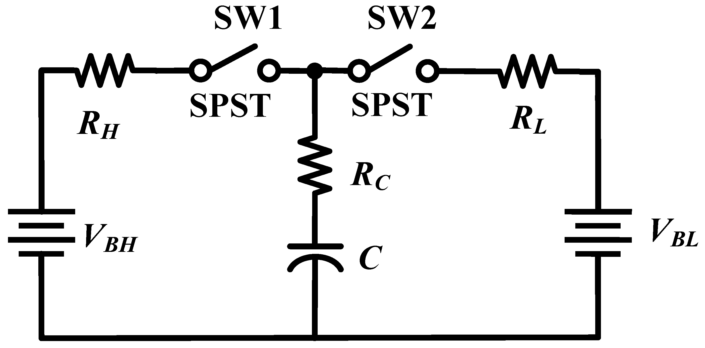
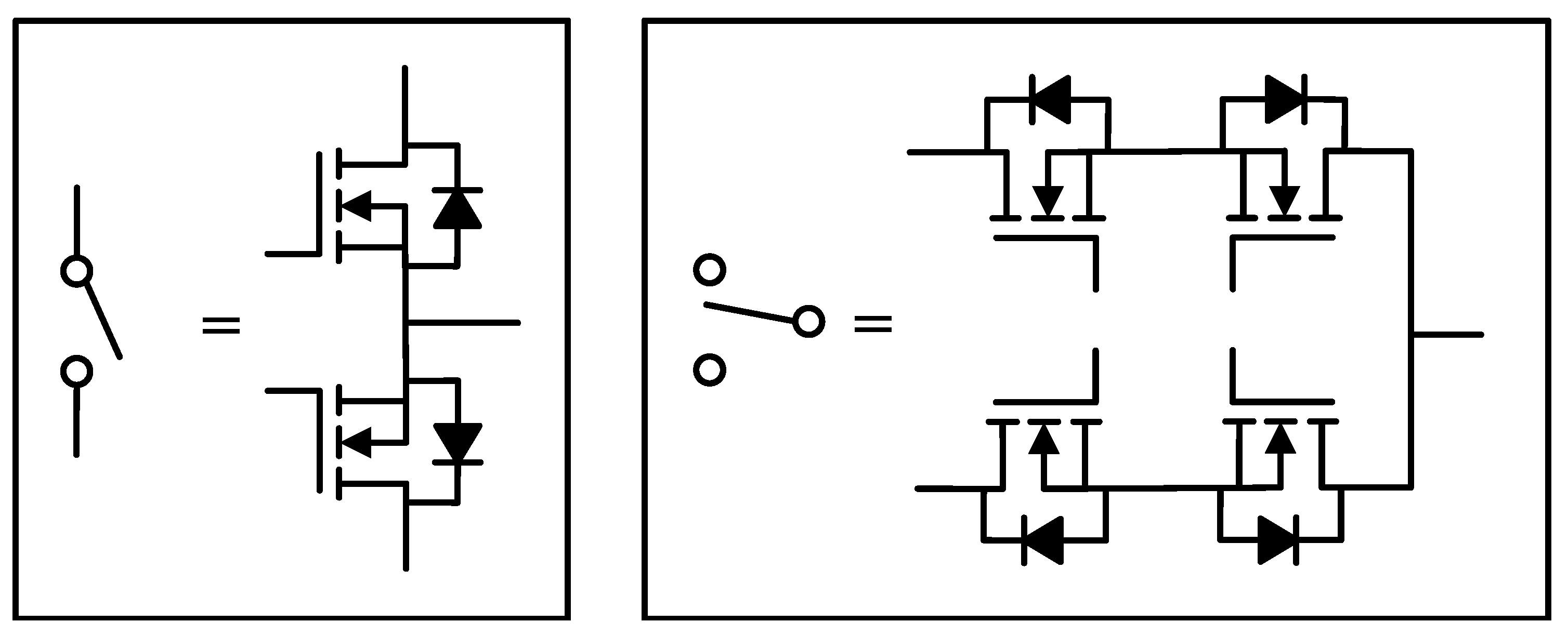
2. Capacitor-Based Battery Equalizer Architecture and Model

The fundamental principle of a capacitor-based battery equalizer is to use a capacitor as an intermediary for energy transfer. Initially, energy from a high-voltage battery is transferred to the capacitor, equalizing the capacitor’s voltage with that of the high-voltage battery. Subsequently, through power switches, the energy is transferred from the capacitor to a low-voltage battery by connecting the capacitor’s terminals to the positive and negative terminals of the low-voltage battery. In Figure 1, V B H and V B L denote batteries with higher and lower voltages, respectively. This process is facilitated by high-frequency periodic switching, enabling efficient energy transfer and distribution, and achieving the goal of voltage balance among all the batteries in the pack, as shown in Figure 2. The symbols R H and R L represent the aggregate resistances during the charging and discharging phases, respectively. These lumped resistances typically encompass the on-state resistance of the deployed single-pole, double-throw (SPDT) switches, the internal resistance of the batteries, and the resistance of the layout traces. R C is defined as the equivalent series resistance (ESR) of the capacitor. The switching devices used in capacitor-based equalizers are typically single-pole, single-throw (SPST) switches.
Ref. [39] indicates that these SPST switches are typically implemented using a single power switch. This means that in certain situations where the switch should be off, the use of a single Mosfet power switch can lead to undesired operations due to the internal parasitic diode forming a loop in the circuit. Such a configuration is not suitable for capacitor-based battery equalizers as it results in leakage currents.Therefore, to ensure that the capacitor-based equalizer operates correctly and adheres to its operating principles, the capacitor-based battery equalizer described in this paper utilizes power switches arranged in a back-to-back configuration. As shown in Figure 3, an SPST switch requires only one set of back-to-back power switches. To construct an SPDT switch, two sets of back-to-back power switches can be used, controlled by complementary switching signals to achieve the desired functionality. The efficiency of energy transfer is affected by several parameters, including the switching frequency of the switches, the capacitance value, the voltage difference between the batteries, the equivalent resistance of the circuit, and the conduction period of the switches. A similar model is discussed in [26].
The charging and discharging actions of the capacitor equalizer can be referred to in Figure 1. As shown in Figure 2, the energy transfer occurs when the normally open power switch is conducting, allowing the high-energy battery to charge the capacitor, starting at an initial voltage V C L .
As the charging process progresses, the capacitor voltage begins to rise until it stops when the normally open switch cuts off, reaching a stop voltage V C H . The cutting off of the normally open switch signifies that the normally closed switch begins conducting, at which point the energy stored in the capacitor starts transferring to the low-energy battery. The circuit repeats this switching mode until the voltages of the batteries are equalized. The charging process and the capacitor voltage can be described by Equations (1) and (2). If the duty cycles of the normally open and normally closed switches are equal, the corresponding capacitor current can be expressed by Equation (3).
V C H = ( V B H V C L ) · e D T τ + V C L
V C L = V C H ( V C H V B L ) · e ( 1 D ) T / τ
I C = C · Δ V Δ T = V C H V C L 0.5 · Δ T V C H V C L 0.5 · Δ T = C · f s w · ( V C H V C L )
For the capacitor-based battery equalizer, the duty cycles D and 1-D are typically the same. f s w represents the switching frequency, and Δ T denotes the time for charging or discharging. Additionally, the equivalent resistances are nearly equal; according to [26], that is, D = 1-D = 0.5. The main reason for setting the same complementary duty cycle is to make the time for the battery to discharge the capacitor and the time for the capacitor to discharge the battery consistent. At the same time, in the battery equalizer architecture proposed in this article, the SPDT switch employed is composed of two sets of SPST switches, so it also needs complementary signals to drive. At the same time, complementary signals have the advantage of simple implementation in the production of hardware circuits. After complying with the work cycle settings mentioned above, solving Equations (4) and (5) for V C H and V C L yields
V C H = V B H + V B L · e D T τ 1 + e D T τ
V C L = V B H + V B L · e D T τ 1 + e D T τ

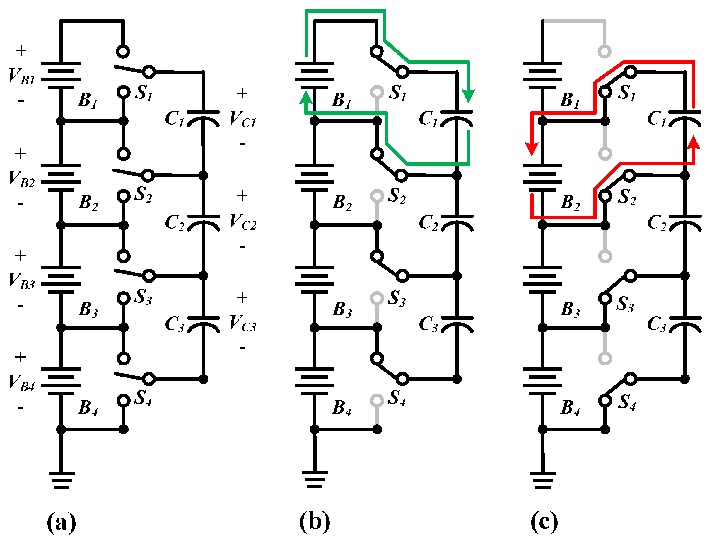
3. Operating Principle and Simulation Results of Capacitor-Based Battery Equalizer

The system is based on the conventional capacitor-based battery equalizer, as shown in Figure 4a. In the part connected to the battery, SPDT switches are used, which are synchronously controlled with a fixed switching frequency. These SPDT switches are electronic, implemented through power semiconductor devices, and alternately connected to the upper and lower ends with the same duty cycle and appropriate dead time. As can be seen in Figure 4b,c, the operation is divided into two phases based on the connection method of the switches. In the first phase, each capacitor is paralleled with the battery above it, causing the capacitor voltage to approach the battery voltage, thereby transferring or absorbing energy to the upper battery. In the second phase, the capacitor is paralleled with the battery below it to transfer energy to reach a new voltage level. After several such processes, the energy in the two batteries will be balanced. The main advantages of this method include high efficiency, suitability for various power devices, and low complexity without the need for sensors or a closed-loop control system. However, in the later stages of the balancing process, the voltage difference between adjacent batteries is small, resulting in reduced balancing current, which slows down the balancing speed.
Based on the circuit architecture depicted in Figure 4, this study aimed to understand the operational principles of the circuit and to ensure its reliability by further assessing the behavioral patterns of the circuit’s operation. To validate the functionality and operating principles of the circuit, Plexim’s simulation software, PLECS version 4.8, was employed. In this research, a capacitor-based battery equalizer circuit structure, incorporating modular power switches, was implemented within PLECS to simulate the voltage balancing process of the battery array. The operating voltage range of the batteries was set between 3 V and 4 V, with the equivalent capacitance being several thousand farads. To reduce the simulation time, the cell’s equivalent capacitance was set to 1 F, while other parameters remained unchanged, as shown in Table 1. Simulation specifications were cross-validated against four voltage scenarios listed in Table 2. The simulation results are presented in Figure 5, which demonstrate that battery balance was achieved in all four different battery voltage scenarios. This confirms the feasibility of using modular SPDT switches in conventional battery equalizers.

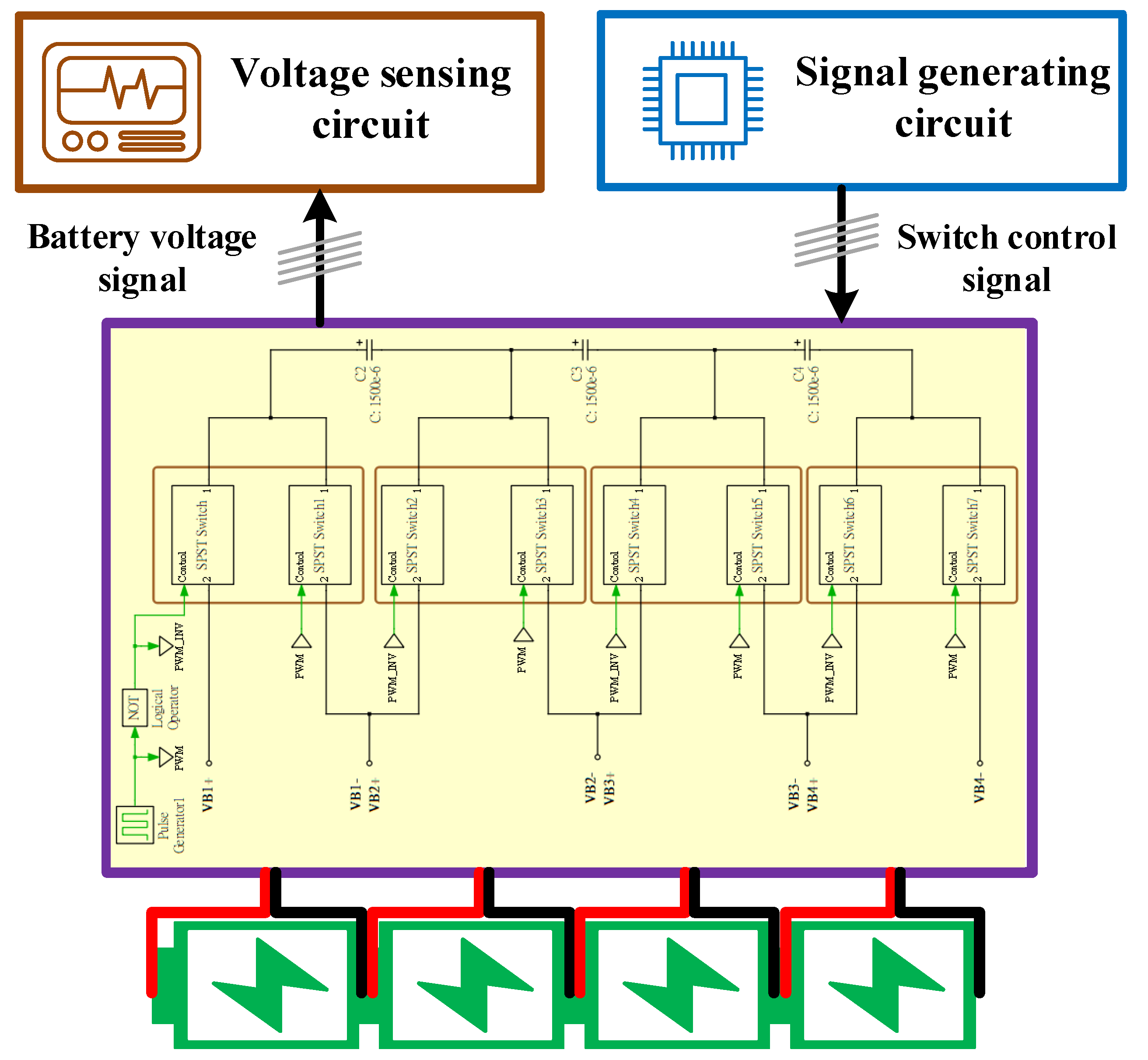
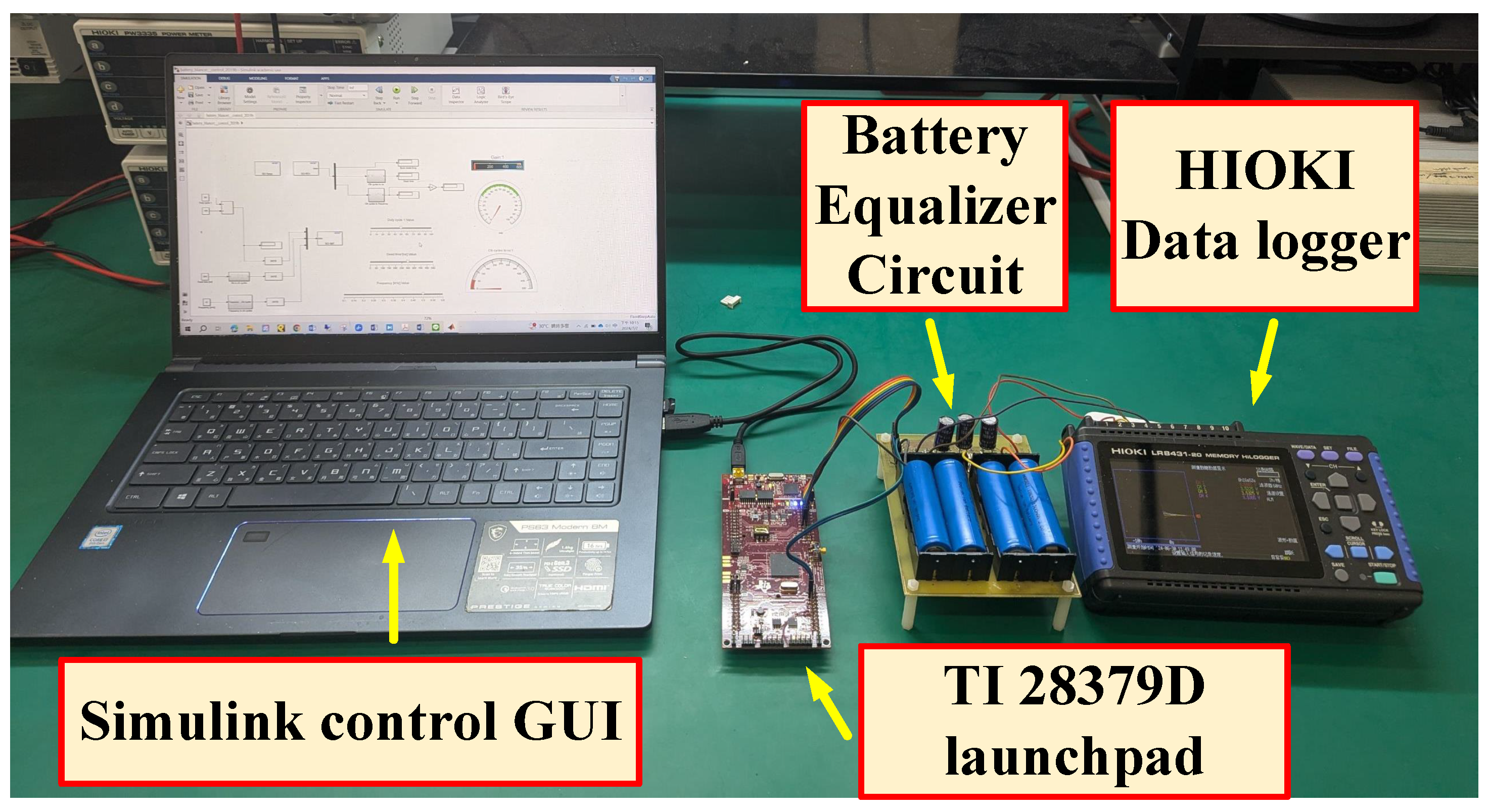
4. Hardware Prototype and Testing Platform

Due to the inherent characteristics of power semiconductor switches, including the parasitic diode, the use of a single power switch to realize an SPST switch can lead to erroneous operation when the voltage difference between the battery and the capacitor exceeds the forward conduction voltage of the parasitic diode within the switch during the off state. To achieve an electronic version of the SPST switch, two power switches connected in a back-to-back configuration are required to prevent leakage currents. However, the switching capacitor equalizer in this study utilizes an SPDT switch, which can be achieved by combining two sets of SPST switches controlled with synchronized timing, as shown in Figure 3. Implementing a fully functional electronic SPDT switch requires four power switches, which in turn necessitates a complex driving circuit and a significant number of peripheral electronic components to maintain electrical isolation. However, given the application scenario of underwater devices, the limited space available, and the high demand for robust electrical isolation, these factors significantly increase the complexity of the equalizer system design [4]. Consequently, this paper proposes a modular integration approach using isolated drivers combined with electronic SPDT switches, which is discussed in detail.
The hardware circuit was designed based on the battery specifications for general-purpose underwater vehicles, configured in a 4-series 1-parallel array. In the hardware experiments, an 18650 1500 mAh sodium-ion battery with a capacity of 1500 mAh was used. The remaining parameter specifications and settings are consistent with those listed in Table 1 for the simulations. As previously discussed, the electronic SPDT switch complicates the circuit design due to the need for a significant number of peripheral electronic components. Additionally, fulfilling the requirements for electrical isolation results in an increase in circuit volume, which can pose challenges for system integration when installed in underwater devices. Consequently, this research proposes the use of a solid-state relay (SSR) isolated driver composed of LED and phototransistors for the hardware circuit design. Solid-state relays integrate power switches and isolated drive circuits within a single integrated circuit package, substantially simplifying the system design. Compared with traditional electronic SPDT switches, solid-state relays offer smaller sizes (high integration), lower power consumption, higher isolation voltages, and a broader operating temperature range. Taking all these advantages into account, this study centers on using solid-state relays for both circuit design and functional validation, with the system architecture depicted in Figure 6.
The key highlight of the proposed new equalizer system is the integration of Toshiba Semiconductor’s TLP3019A solid-state relay [40] into the circuit architecture, as illustrated in Figure 7. This relay includes a pair of back-to-back power switches for switching and a set of optoisolators to achieve complete electrical isolation and switch driving. This solid-state relay features a reverse withstand voltage of 100 V, a maximum conducting current of 3 A, and a conduction resistance of 65 m Ω . The control core of the capacitor-based battery equalizer system is designed for simplicity, requiring only a PWM signal to control the electronic SPDT switch. This enables natural energy transfer based on the voltage differences between batteries until voltage uniformity is achieved within the battery pack, thus completing the balancing process without the need for sensing circuits, which reduces hardware development costs. Due to testing requirements, this study employs Texas Instruments DSP F28379D Launchpad, which provides four sets of PWM outputs to control the solid-state relay. A GUI interface developed using MATLAB/SIMULINK version 2020a allows for the monitoring and adjustment of the PWM signals frequency, duty cycle, and dead time, thus simplifying the circuit testing process.

5. Experimental Results

Using the previously mentioned PLECS simulation platform, the correctness and feasibility of the equalizer have been validated. Subsequently, a battery pack comprising four series-connected cells combined with an opto-relay was used to realize an isolated and modular SPDT power switch, integrating the traditional battery equalizer architecture for testing. The practical and simulated results were compared against four battery voltage scenarios, as outlined in Table 2. Figure 8 displays the actual testing setup including the equalizer circuit, battery pack, microprocessor, data acquisition system, and the Simulink control platform for signal monitoring and control. This circuit platform encompasses various nonlinear component characteristics and temperature variations among other nonideal conditions, allowing for a more accurate validation of the proposed modular power switch application in battery equalizers. The experimental results of the tests conducted under the four scenarios detailed in Table 2 are shown in Figure 9.
In Figure 9, VB1 to VB4 represent the voltages of each battery within a series of four battery cells. By placing the battery with the highest voltage in different positions within this series, we can observe four distinct scenarios. The results indicate that the highest voltage battery can effectively transfer energy to batteries with lower voltages from any position in the series, thereby achieving battery balance. The results indicate that the battery voltages in all scenarios were perfectly balanced, with voltage differences below 50 mV, and were consistent with the voltage trends displayed on the simulation platform.

6. Conclusions

This paper presents a novel capacitor-based equalizer design, highly suitable for underwater vehicle applications, thereby extending the lifespan of battery packs. Compared with other circuit designs, this study proposes the use of an opto-relay as the core framework for circuit design. The internal structure of the opto-relay consists of a back-to-back power switch module, which, compared with discrete electronic components configured as back-to-back switches, reduces the number of electronic components used and simplifies the drive circuit design. Moreover, the use of optoisolators not only ensures high-intensity electrical isolation between the power switch module and the controller but also provides the crucial benefit of galvanic isolation. This meets the stringent requirements for high circuit density and robust isolation, essential in underwater applications. Moreover, the use of optoisolators ensures high-intensity electrical isolation between the power switch module and the controller, meeting the need for high circuit density and robust isolation required in underwater applications. To validate the feasibility of the proposed solution, this study utilizes the circuit simulation software PLECS version 4.8 for functional validation to ensure the viability of its architecture and employs Simulink’s GUI interface for experimental system monitoring. Additionally, a detailed description, implementation, and evaluation of the equalizer hardware circuit and balancing results are provided. The advantages of this architecture include its ability to provide a compact and reliable battery balancing device in harsh and space-constrained environments, making it a preferred solution for underwater electric vehicle applications.

Funding

This research received no external funding.

Institutional Review Board Statement

Not applicable.

Informed Consent Statement

Not applicable.

Data Availability Statement

All collected data are presented in the manuscript.

Acknowledgments

The author appreciates the National Formosa University for providing experimental equipment.

Conflicts of Interest

The authors declare no conflicts of interest.

References

  1. Paull, L.; Saeedi, S.; Seto, M.; Li, H. AUV navigation and localization: A review. IEEE J. Ocean. Eng. 2013, 39, 131–149. [Google Scholar] [CrossRef]
  2. Sands, T. Development of deterministic artificial intelligence for unmanned underwater vehicles (UUV). J. Mar. Sci. Eng. 2020, 8, 578. [Google Scholar] [CrossRef]
  3. Depcik, C.; Cassady, T.; Collicott, B.; Burugupally, S.P.; Li, X.; Alam, S.S.; Arandia, J.R.; Hobeck, J. Comparison of lithium ion Batteries, hydrogen fueled combustion Engines, and a hydrogen fuel cell in powering a small Unmanned Aerial Vehicle. Energy Convers. Manag. 2020, 207, 112514. [Google Scholar] [CrossRef]
  4. Manley, J.E.; Smith, J. Rapid development and evolution of a micro-UUV. In Proceedings of the OCEANS 2017-Anchorage, Anchorage, AK, USA, 18–21 September 2017; pp. 1–4. [Google Scholar]
  5. Gezer, E.C.; Zhao, L.; Beason, J.; Zhou, M. Towards seafloor mapping using an affordable micro-UUV. In Proceedings of the OCEANS 2021: San Diego–Porto, San Diego, CA, USA, 20–23 September 2021; pp. 1–5. [Google Scholar]
  6. Underwater Vehicle Charging. Available online: https://www.energy.gov/sites/default/files/2019/09/f66/73355-3.pdf (accessed on 8 August 2024).
  7. Orekan, T.; Zhang, P.; Shih, C. Analysis, design, and maximum power-efficiency tracking for undersea wireless power transfer. IEEE J. Emerg. Sel. Top. Power Electron. 2017, 6, 843–854. [Google Scholar] [CrossRef]
  8. Liu, J.W.; Cheng, Y.S.; Ho, K.C. Development of a Wireless Charging System based on LLC Resonant Converter for Underwater Drone. In Proceedings of the 2023 11th International Conference on Power Electronics and ECCE Asia (ICPE 2023-ECCE Asia), Jeju Island, Republic of Korea, 22–25 May 2023; pp. 2579–2584. [Google Scholar]
  9. Deebak, B.D.; Al-Turjman, F. Aerial and underwater drone communication: Potentials and vulnerabilities. In Drones in Smart-Cities; Elsevier: Amsterdam, The Netherlands, 2020; pp. 1–26. [Google Scholar]
  10. Guida, R.; Demirors, E.; Dave, N.; Melodia, T. Underwater ultrasonic wireless power transfer: A battery-less platform for the internet of underwater things. IEEE Trans. Mob. Comput. 2020, 21, 1861–1873. [Google Scholar] [CrossRef]
  11. Mohsan, S.A.H.; Khan, M.A.; Mazinani, A.; Alsharif, M.H.; Cho, H.S. Enabling underwater wireless power transfer towards sixth generation (6g) wireless networks: Opportunities, recent advances, and technical challenges. J. Mar. Sci. Eng. 2022, 10, 1282. [Google Scholar] [CrossRef]
  12. Lin, M.; Lin, R.; Yang, C.; Li, D.; Zhang, Z.; Zhao, Y.; Ding, W. Docking to an underwater suspended charging station: Systematic design and experimental tests. Ocean Eng. 2022, 249, 110766. [Google Scholar] [CrossRef]
  13. Yoshida, H.; Hyakudome, T.; Aoki, T.; Fujiya, N.; Konno, S.; Oomiya, M.; Ozawa, K. Improvement of a high energy type lithium-ion battery system for unmanned underwater vehicle. In Proceedings of the ISOPE International Ocean and Polar Engineering Conference, Osaka, Japan, 21–26 July 2009; ISOPE: Mountain View, CA, USA, 2009; p. 690. [Google Scholar]
  14. Toh, W.D.; Xu, B.; Jia, J.; Chin, C.S.; Chiew, J.; Gao, Z. Lithium iron phosphate (LiFePO4) battery power system for deepwater emergency operation. Energy Procedia 2017, 143, 348–353. [Google Scholar] [CrossRef]
  15. Wang, Y.F.; Wu, J.T. Performance improvement of thermal management system of lithium-ion battery module on purely electric AUVs. Appl. Therm. Eng. 2019, 146, 74–84. [Google Scholar] [CrossRef]
  16. Mao, Z.; Yan, S. Design and analysis of the thermal-stress coupled topology optimization of the battery rack in an AUV. Ocean Eng. 2018, 148, 401–411. [Google Scholar] [CrossRef]
  17. Ataner, E.; Özdeş, B.; Öztürk, G.; Çelik, T.Y.C.; Terzioğlu, H.; Durdu, A. Design of communication and power systems in unmanned underwater vehicles. Avrupa Bilim Teknol. Derg. 2020, 262–267. [Google Scholar] [CrossRef]
  18. Yar, G.N.A.H.; Ahmad, A.; Khurshid, K. Low cost assembly design of unmanned underwater vehicle (UUV). In Proceedings of the 2021 International Bhurban Conference on Applied Sciences and Technologies (IBCAST), Islamabad, Pakistan, 12–16 January 2021; pp. 829–834. [Google Scholar]
  19. Huang, H.; Lai, Z.; Zhang, X.; Liu, X.; Yi, H.; Zhuo, F. Design and Energy Management Comparison of Fuel Cell Hybrid Power System for Underwater Unmanned Vehicle. In Proceedings of the 2021 IEEE Sustainable Power and Energy Conference (iSPEC), Nanjing, China, 23–25 December 2021; pp. 3630–3635. [Google Scholar]
  20. Yang, Y.D.; Hu, K.Y.; Tsai, C.H. Digital battery management design for point-of-load applications with cell balancing. IEEE Trans. Ind. Electron. 2019, 67, 6365–6375. [Google Scholar] [CrossRef]
  21. Zahedmanesh, A.; Muttaqi, K.M.; Sutanto, D. A sequential decision-making process for optimal technoeconomic operation of a grid-connected electrical traction substation integrated with solar PV and BESS. IEEE Trans. Ind. Electron. 2020, 68, 1353–1364. [Google Scholar] [CrossRef]
  22. Ouyang, Q.; Han, W.; Zou, C.; Xu, G.; Wang, Z. Cell balancing control for lithium-ion battery packs: A hierarchical optimal approach. IEEE Trans. Ind. Inform. 2019, 16, 5065–5075. [Google Scholar] [CrossRef]
  23. Vulligaddala, V.B.; Vernekar, S.; Singamla, S.; Adusumalli, R.K.; Ele, V.; Brandl, M.; Srinivas, M.B. A 7-cell, stackable, li-ion monitoring and active/passive balancing IC with in-built cell balancing switches for electric and hybrid vehicles. IEEE Trans. Ind. Inform. 2019, 16, 3335–3344. [Google Scholar] [CrossRef]
  24. Shang, Y.; Zhao, S.; Fu, Y.; Han, B.; Hu, P.; Mi, C.C. A lithium-ion battery balancing circuit based on synchronous rectification. IEEE Trans. Power Electron. 2019, 35, 1637–1648. [Google Scholar] [CrossRef]
  25. Raeber, M.; Heinzelmann, A.; Abdeslam, D.O. Analysis of an active charge balancing method based on a single nonisolated DC/DC converter. IEEE Trans. Ind. Electron. 2020, 68, 2257–2265. [Google Scholar] [CrossRef]
  26. Ho, K.C.; Liu, Y.H.; Ye, S.P.; Chen, G.J.; Cheng, Y.S. Mathematical modeling and performance evaluation of switched-capacitor-based battery equalization systems. Electronics 2021, 10, 2629. [Google Scholar] [CrossRef]
  27. Farzan Moghaddam, A.; Van den Bossche, A. An efficient equalizing method for lithium-ion batteries based on coupled inductor balancing. Electronics 2019, 8, 136. [Google Scholar] [CrossRef]
  28. Cui, X.; Shen, W.; Zhang, Y.; Hu, C. A fast multi-switched inductor balancing system based on a fuzzy logic controller for lithium-ion battery packs in electric vehicles. Energies 2017, 10, 1034. [Google Scholar] [CrossRef]
  29. Noh, G.; Lee, J.; Ha, J.I. Design and analysis of single-inductor power converter for both battery balancing and voltage regulation. IEEE Trans. Ind. Electron. 2021, 69, 2874–2884. [Google Scholar] [CrossRef]
  30. Al-Smadi, M.K.; Qahouq, J.A.A. Generalized Analysis and Evaluation of Switched Inductor PWM-based Lithium-ion Battery Cell Balancing. In Proceedings of the 2022 IEEE Energy Conversion Congress and Exposition (ECCE), Detroit, MI, USA, 9–13 October 2022; pp. 1–5. [Google Scholar]
  31. Park, S.H.; Kim, T.S.; Park, J.S.; Moon, G.W.; Yoon, M.J. A new battery equalizer based on buck-boost topology. In Proceedings of the 2007 7th Internatonal Conference on Power Electronics, Daegu, Republic of Korea, 22–26 October 2007; pp. 962–965. [Google Scholar]
  32. Lee, Y.S.; Cheng, G.T. Quasi-resonant zero-current-switching bidirectional converter for battery equalization applications. IEEE Trans. Power Electron. 2006, 21, 1213–1224. [Google Scholar] [CrossRef]
  33. Shi, F.; Song, D. A novel high-efficiency double-input bidirectional DC/DC converter for battery cell-voltage equalizer with flyback transformer. Electronics 2019, 8, 1426. [Google Scholar] [CrossRef]
  34. Farzan Moghaddam, A.; Van den Bossche, A. Forward converter current fed equalizer for lithium based batteries in ultralight electrical vehicles. Electronics 2019, 8, 408. [Google Scholar] [CrossRef]
  35. Gallardo-Lozano, J.; Romero-Cadaval, E.; Milanes-Montero, M.I.; Guerrero-Martinez, M.A. Battery equalization active methods. J. Power Sources 2014, 246, 934–949. [Google Scholar] [CrossRef]
  36. Ye, Y.; Cheng, K.W.E. An automatic switched-capacitor cell balancing circuit for series-connected battery strings. Energies 2016, 9, 138. [Google Scholar] [CrossRef]
  37. Kim, M.Y.; Kim, C.H.; Kim, J.H.; Moon, G.W. A chain structure of switched capacitor for improved cell balancing speed of lithium-ion batteries. IEEE Trans. Ind. Electron. 2013, 61, 3989–3999. [Google Scholar] [CrossRef]
  38. Chin, C.S.; Jia, J.; Chiew, J.H.K.; Da Toh, W.; Gao, Z.; Zhang, C.; McCann, J. System design of underwater battery power system for marine and offshore industry. J. Energy Storage 2019, 21, 724–740. [Google Scholar] [CrossRef]
  39. Yang, Z.Z. Development of an active equalizer for lithium-ion batteries. Electronics 2022, 11, 2219. [Google Scholar] [CrossRef]
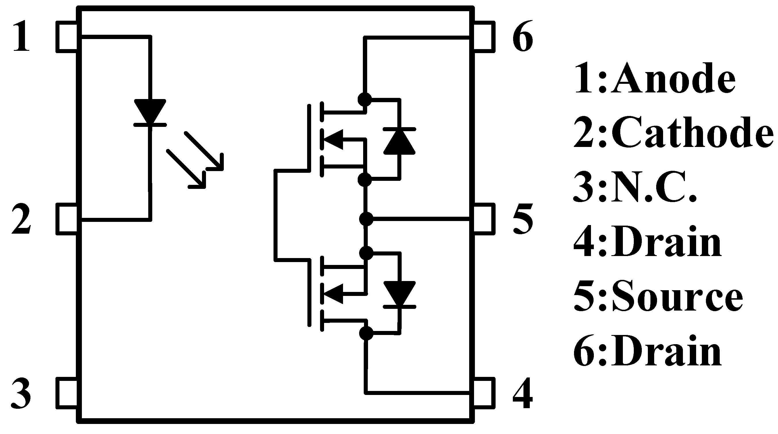
  40. Toshiba. TLP3109A Datasheet. 2023. Available online: https://toshiba.semicon-storage.com/info/TLP3109A_datasheet_en_20230525.pdf?did=65124&prodName=TLP3109A (accessed on 8 August 2024).
Figure 1. Waveforms of the capacitor voltage during balancing processes [26].
Jmse 12 01357 g001
Figure 2. Schematic of energy transfer in a capacitor-based equalizer (illustrated with two batteries) [26].
Jmse 12 01357 g002
Figure 3. Electronic SPST and SPDT power switches.
Jmse 12 01357 g003
Figure 4. Conventional capacitor-based battery equalizer: (a) circuit architecture; (b) first state; (c) second state [26].
Jmse 12 01357 g004
Figure 5. Capacitor-based battery equalizer simulation result.
Jmse 12 01357 g005
Figure 6. Capacitor-based battery equalizer hardware verification platform.
Jmse 12 01357 g006
Figure 7. Modular electronic SPST switch (TLP3109A) [40].
Jmse 12 01357 g007
Figure 8. Experimental platform of battery equalizer system.
Jmse 12 01357 g008
Figure 9. Four different voltage scenarios are employed to balance a four-cell battery pack using a switched capacitor equalizer.
Jmse 12 01357 g009
Table 1. Simulation parameters of the battery equalizer.
Specification ItemsParameters
Cell Voltage ( V C )3–4 V
Cell Capacity ( V B )1 F
Switch Resistance ( R s w ) 65 m Ω
Capacitor (C)1500 uF
Capacitor ESR (ESR) 30 m Ω
Switching Frequency ( f s w )500 Hz
Duty Cycle (D)50%
Dead Time300 ns
Table 2. Four scenarios for different initial conditions.
Initial Voltage (V) V B 1 V B 2 V B 3 V B 4
Scenario 13.983.783.543.01
Scenario 23.833.074.003.61
Scenario 33.513.963.053.83
Scenario 43.033.473.723.98
Disclaimer/Publisher’s Note: The statements, opinions and data contained in all publications are solely those of the individual author(s) and contributor(s) and not of MDPI and/or the editor(s). MDPI and/or the editor(s) disclaim responsibility for any injury to people or property resulting from any ideas, methods, instructions or products referred to in the content.

