Article

Development of an Extensional Fault System and Its Control on Syn-Rift Sedimentation: Insights from 3D Seismic Interpretation of the Weixinan Depression, Northern South China Sea

1
College of Marine Science and Technology, China University of Geosciences, Wuhan 430074, China
2
Hubei Key Laboratory of Marine Geological Resources, China University of Geosciences, Wuhan 430074, China
3
Southern Exploration and Development Company, Sinopec, Chengdu 610041, China
4
School of Earth Resources, China University of Geosciences, Wuhan 430074, China
*
Authors to whom correspondence should be addressed.
J. Mar. Sci. Eng. 2024, 12(8), 1392; https://doi.org/10.3390/jmse12081392
Submission received: 16 July 2024 / Revised: 5 August 2024 / Accepted: 8 August 2024 / Published: 14 August 2024

Abstract

:
The impacts of the growth and linkage of fault segments on sedimentation in a lacustrine rift basin, the Weixinan Depression, the Beibuwan Basin, in the northern South China Sea, which has been demonstrated to have huge petroleum potential, are elucidated on the basis of well-constrained 3D seismic data. Two main fault systems, the No. 1 boundary fault system and the No. 2 fault system, were developed in the Weixinan Depression. The evolution of the lower basement is based on the No. 1 fault system, which controls the distribution of depocenters (ranging from 450–800 m) within the lower structural layer. It includes the five fault segments isolated at the initial stage, the interaction and propagation stage, the linkage stage, and the decline stage. The No. 2 fault system governs the deposition of the upper structural layer with a series of discrete depocenters in the hangingwall. Initially, it comprises several right-order echelon branching faults. Each branch fault rapidly reached the existing length and maintained a constant length while establishing soft links with each other in the subsequent displacement accrual. The development of topographic slopes, transition zones, transverse anticlines, and related fault troughs and gullies related to the activity of the No. 1 boundary fault system is the main controlling factor that induces the differential development of the western, middle, and eastern sections of steep slope fans. The differential subsidence effect along the No. 2 fault system is responsible for the multiple ‘rising-stable’ stage changes in the relative lake level during the development of axial delta deposits. This study will help elucidate the different controls of extensional fault systems on associated sedimentation, as well as rift basin development in the South China Sea and similar areas throughout the world.

1. Introduction

The evolution of rift basins is closely related to the activity of large normal extensional fault systems [1,2,3,4,5,6,7,8], which commonly experience a series of fault growth events and linkages [9,10,11,12,13,14,15]. Fault growth and linkage represent kinematic processes that have been identified as crucial mechanisms influencing sediment distribution and rift basin evolution [7,16,17,18,19]. Therefore, determining the impact of the development and geometry of extensional fault systems on syn-rift sedimentation by focusing on the growth and linkage of fault segments is highly important [20,21,22,23,24,25].
In the past few decades, extensive research has been conducted to elucidate the relationships among extensional fault growth and linkages and their impacts on syn-rift sedimentation in China, such as in the Erlian Basin [26], the Bohai Basin [27], the Songliao Basin [7], the northern Gulf of Suez Rift in Egypt [28], the Taranaki Basin in New Zealand [29], and the Enderby Terrace in the NW Shelf of Australia [8]. However, most of these studies have focused on the effect of one kind of fault system, mainly boundary fault linkages, on sedimentation. Furthermore, the kinematics and geometry of extensional faults and their control on syn-rift sedimentation still need to be further studied.
The Beibuwan Basin is located on the northwestern margin of the South China Sea and runs along the eastern Red River Fault Zone (Figure 1). The formation and evolution of the Beibuwan Basin are intricately linked with tectonic events, including the subduction of the Paleo-Pacific Plate and Proto-South China Sea, the opening of the South China Sea, and strike-slip movement along the Red River Fault Zone [30,31,32,33,34]. Multistage tectonic activity has contributed to a unique fault system in the Beibuwan Basin [35,36,37,38,39]. Previous studies of the Beibuwan Basin have focused mainly on reservoir quality and organic geochemistry [40,41,42,43,44,45]; little is known about the development of extensional fault systems and their control of syn-rift sedimentation [39,40].
In recent years, extensive hydrocarbon explorations conducted in the Cenozoic Beibuwan Basin have yielded a considerable amount of three-dimensional high-resolution seismic reflection data. Recent seismic reflection data reflect complicated fault systems, enabling a detailed examination of the development of extensional fault systems and their control of syn-rift sedimentation. Therefore, in this study, recent 3D seismic reflections were used to illustrate the characteristics of two selected distinctive fault systems that developed in the Paleogene strata of the Weixinan Depression, Beibuwan Basin of the northern South China Sea, and related syn-rift sedimentation in response to the growth and linkage of different fault systems. This study aims to explain the temporal and spatial variability in sedimentation of two fault systems in rift basins in South China Sea areas, which has implications for other rift basins with similar fault systems around the world.

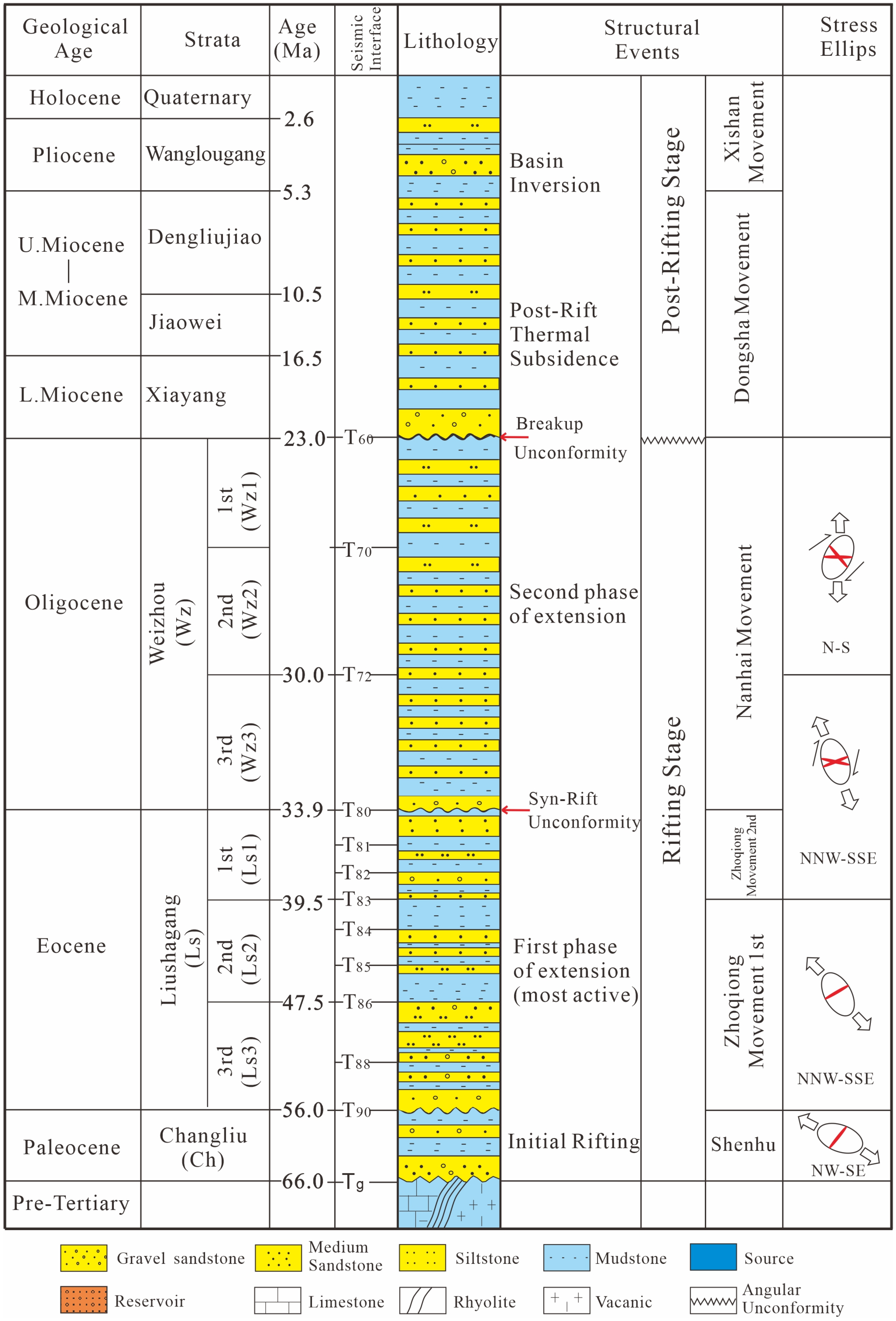
2. Geological Setting

The Cenozoic Beibuwan Basin in the northern South China Sea is an extensional basin situated along the eastern margin of the Red River Fault Zone (Figure 1A) [46]. The Beibuwan Basin is characterized by three uplifts and eight depressions (Figure 1B) [40]. The Weixinan Depression is in the northwestern part of the basin, along the Weixinan Uplift to the south, the Yuegui Uplift to the north, and the Qixi Uplift to the southeast (Figure 1C). The Weixinan Depression, spanning an area of 2300 km2, consists of three distinct sags, namely, Sag A, Sag B, and Sag C. The two stages of evolution of the Cenozoic Beibuwan Basin were identified as the rifting stage from the Paleocene to the Oligocene and the post-rifting stage from the Miocene to the present (Figure 2) [40,47]. The rifting stage consists of intensive rifting structures and fault-bound sequences, while the post-rifting stage is characterized by weak fault activity and draping strata [35,48,49]. In the Weixinan Depression, two fault systems emerged in the Paleogene, namely, the No. 1 fault system located along the northern boundary and the No. 2 fault system comprising a series of en-echelon faults within the central region of the depression (Figure 1).
The Paleogene syn-rifting strata comprises three formations, the Paleocene Changliu Formation (Ch, 66–56 Ma), the Eocene Liushagang Formation (Ls, 56–33.9 Ma), and the Oligocene Weizhou Formation (Wz, 33.9–23 Ma). The Neogene and Quaternary post-rifting sequences include the Xiayang, Jiaowei, Dengliujiao, and Wanglougang formations [50]. In this study, the Eocene Liushagang Formation and Oligocene Weizhou Formation were considered as targets. Based on the sequence stratigraphic analysis, the Liushagang Formation can be divided into the upper Ls1 Member (39.5–33.9 Ma), the middle Ls2 Member (47.5–39.5 Ma), and the lower Ls3 Member (56–47.5 Ma) [35]. The Ls3 Member comprised glutenites, sandstones, and mudstones deposited within a braided river delta. The Ls2 Member is characterized by thick dark shales deposited in a lake. In the strata, an interlayer of sandstones and mudstones, developed in braided river delta and sublacustrine fans, was predominant in the Ls1 Member stage. The Weizhou Formation is characterized by fluvial sandstones interbedded with mudstones (Figure 2) [39].

3. Materials and Methods

3.1. Datasets

In this study, 3D seismic reflection data (frequency = 35 Hz), covering a total area of 1600 km2, were used to analyze the fault systems in the Weixinan Depression. The high-quality seismic data enables us to obtain remarkable images of the fault structures formed in the depression. The 3D seismic data employed in this study were obtained from the Zhanjiang branch of China National Offshore Oil Corporation (CNOOC). The sequence stratigraphic interpretation technique was employed to examine the temporal sequence stratigraphic framework across the Weixinan Depression [51,52].

3.2. Fault Kinematic Analysis

The internal architecture and fault activity of both the No. 1 and No. 2 systems were analyzed using 3D seismic data to examine the characteristics and differences between two fault models developed for the Weixinan Depression, thereby elucidating the influence of regional tectonic events in the South China Sea region on the fault architecture. GeoFrame 2012 4.3 version software by Schlumberger, New York, USA was employed to detect the seismic horizons and fault polygons and, subsequently, to illustrate the internal architecture of the No. 1 and No. 2 fault systems. The high-resolution fault mapping was obtained by strictly following the seismic interpretation workflow [53]. Quantitative analysis of fault displacement was conducted by measuring differences in seismic time of cutoffs on the fault plane projected by the hangingwall and footwall of identified seismic profiles. These seismic profiles are orthogonal to the fault strike and spaced at intervals of 200 m. The seismic time data were transformed into depth data using time-depth conversion and the true depths of fault displacements were obtained. The rates of fault activity were computed using the ratio of the fault displacement to the duration of deposition. Throw–length (T–L) plots, which illustrate the fault throw for a particular horizon against a certain distance (the same numerical interval of inlines) along the fault, were generated to analyze the growth and linkage of both the No. 1 and No. 2 fault systems.
Normal fault activity has a direct influence on the extent and location of accommodation, thereby controlling the distribution of syn-sedimentary strata [54,55]. Therefore, in this study, the isopach maps were generated to illustrate variations in fault activity. Although the isopach maps do not provide quantitative and direct indication of fault-driven subsidence, active faults can be identified by the variations in abrupt thickness observed across mapped fault traces on the isopach map. The variations in fault length and fault activity duration are identified by comparing sequential isopach maps.
A balanced cross-section technique based on area balance assumptions was employed to investigate the vertical development of the No. 1 and No. 2 fault systems, as well as the tectonic deformation of the strata. The balanced profiles of inline 4991 were constructed to rebuild the basin evolution stages using the 2D MOVE software of the 2010 version.

4. Structural Style

4.1. The No. 1 Fault System

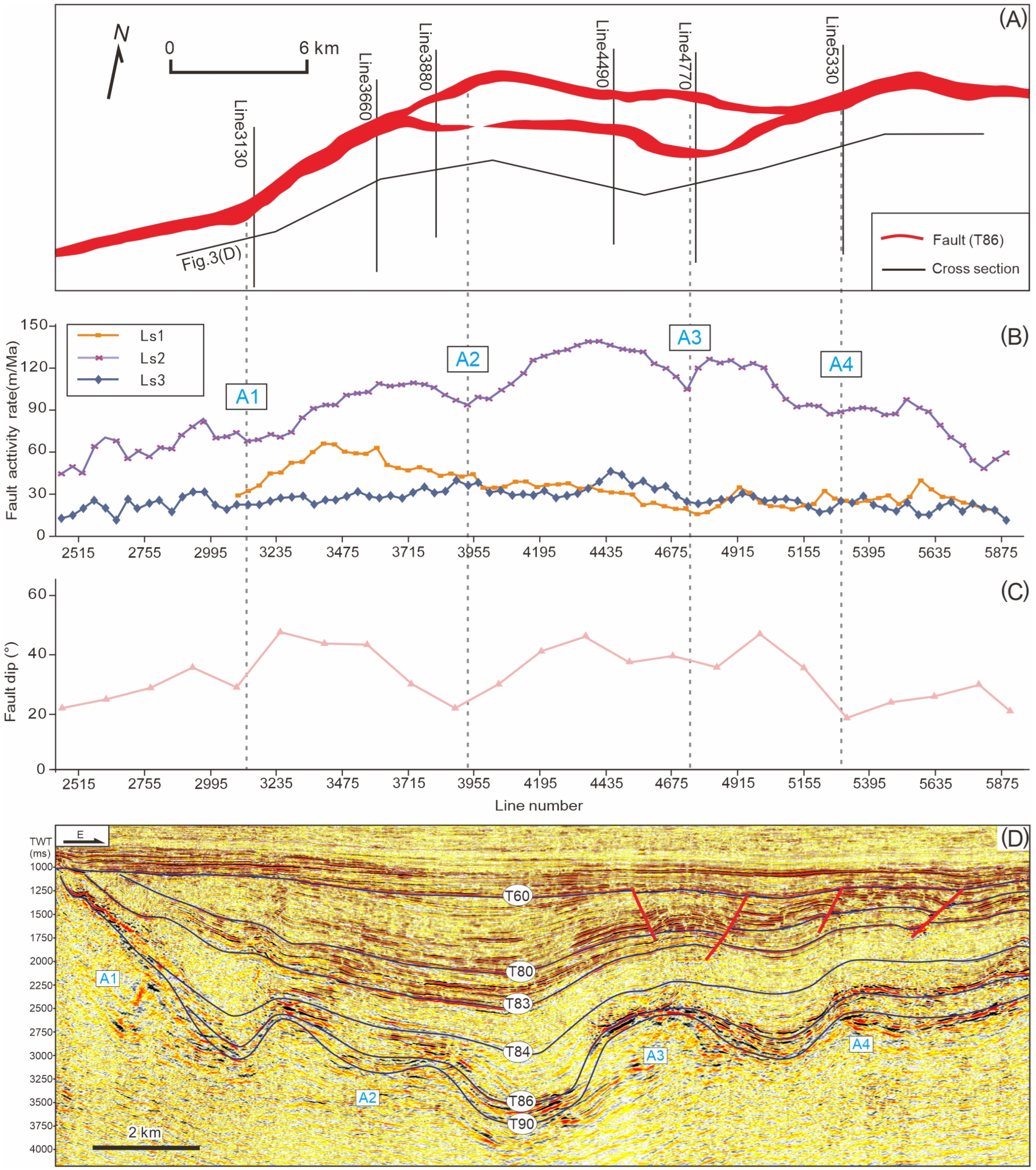
4.1.1. Geometric Morphology and Characteristics of Fault Activity

The No. 1 fault system serves as the boundary control fault in the northern Weixinan Depression, with a length of about 50 km and traversing through T60–T90 strata. It has an overall strike of about 70°, primarily in the NE and NEE direction (Figure 3A). The fault activity of the No.1 fault system varies significantly in different periods and different parts. During the deposition of the Ls3 (T90–T86) Member, the Weixinan depression underwent its initial stage of rifting. Generally, the No.1 fault system exhibited low fault activity rates, ranging from 15 to 50 m/Ma. In the Ls2 (T86–T83) stage, the No. 1 fault system exhibited its maximum activity rate, reaching 40–140 m/Ma. Among different fault systems, the middle section of the No. 1 fault system demonstrated the highest activity rate, with an average greater than 80 m/Ma, followed by the eastern section. The lowest activity rate was observed in the western section. The activity rate of the No. 1 fault system at the Ls1 (T83–T80) stage decreased rapidly and exhibited significant variations in the strike, with a relatively higher activity rate of 30–60 m/Ma in the western section and a lower fault activity rate of less than 30 m/Ma in the middle and eastern sections (Figure 3A,B).
The fault plane of the No. 1 fault system predominantly comprises listric fault, ramp-flat fault, and plate fault. The western (line 2400–3700) and eastern (line 5050–5900) sections of the No. 1 fault system primarily exhibit typical listric normal faults, while the middle section (line 3700–5050) of the No. 1 fault system exhibits a step-like shape within the profile (Figure 4). The western section indicates a gradual increase in fault dip angle from west to east (Figure 3C and Figure 4A,B). The middle section comprises two-stage faults, with one fault in the front and one in the back (Figure 4C–E). The late fault migrated to the rear, with a high fault dip and an extension length of about 18 km (Figure 3A). Compared to the western and middle sections of the No. 1 fault system, the eastern section exhibits a relatively lower fault dip angle (Figure 3C and Figure 4F).

4.1.2. Hangingwall Transverse Anticlines

Large boundary normal faults within extensional basins typically comprise multiple initially isolated fault segments. The predominant mechanism driving its evolution is the propagating model [56,57] (Schwartz and Coppersmith, 1984; Walsh and Waterson, 1988). During the rifting period, as normal faults undergo the process of extension and connection, the transverse folds in the hangingwall develop due to variations in fault activity along the strike. To examine the growth and linkage process of boundary normal faults, it is essential to identify these transverse folds or linkage points.
Four linkage points, namely, A1, A2, A3, and A4 from west to east, are identified in the No. 1 fault system (Figure 3D). These four linkage points correspond to areas of fault activity rates and dip low (Figure 3B,C). The linkage points A1, A2, A3, and A4 are situated close to the inline 3120, inline 3900, inline 4750, and inline 5330, respectively. On the seismic profile, these linkage points appear as mound-shaped uplifts of the underlying basement, referred to as inter-depression uplifts (transverse anticlines), with transverse synclines interspersed between them. During the primary rifting stage of Ls2 (T86–T83), the transverse anticline is significantly prominent, exerting significant control over the distribution of strata. The thickness of the strata varies significantly along the strike and the strata above the transverse anticline are relatively thin. This difference is also evident in the dip section. The profiles illustrated in Figure 4B–D indicate evident wedge-shaped strata, with thickness decreasing from the fault root to the depression, whereas other profiles (Figure 4A,E,F) do not exhibit wedge-shaped strata. During the late period of Ls2, the influence of the transverse anticline was weakened, resulting in a more uniform thickness of strata along the strike. This indicated that the No. 1 fault system had been linked, leading to more uniform overall subsidence.

4.2. The No. 2 Fault System

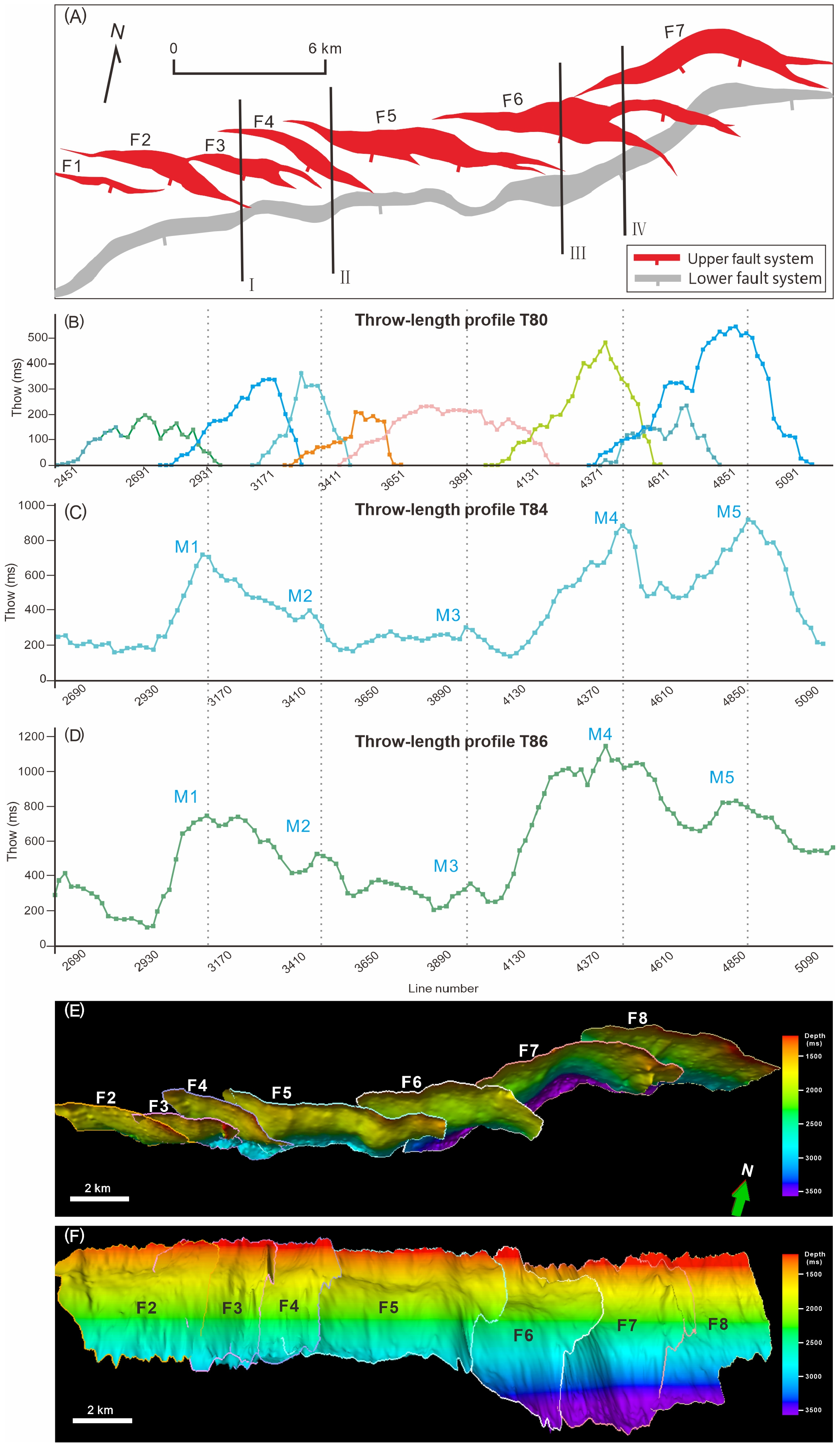
4.2.1. Geometric Morphology and Characteristics of Fault Activity

The No. 2 fault system exhibits two significant characteristics: (1) the upper section of the fault (above the T83 interface) is typically segmented on the plane, with each segmented fault identified by a minor throw on both sides and a major throw in the middle. The throw change of the segmented fault represents a process of transmission. The throw–length curves of each branch of the upper fault are characterized by a minor throw on both sides and a major throw in the middle (Figure 5B). The adjacent faults are connected by fault relay zones. Comparatively, the throw curve of the lower fault illustrates a continuous change. Multiple throw minima, interspersed with throw maxima, are evident along the fault strike (Figure 5C,D). (2) The No. 2 fault system illustrates a typical ramp-flat structure in its profile. The upper section constitutes a listric fault, while the lower section contains a plate fault. The middle fault plane exhibits a gentle slope, resulting in a listric surface, i.e., the ramp-flat structure (Figure 6). Reverse regulating fault and collapse structures typically form above the listric surface (Figure 6). Vertically, the middle section of the upper fault segments is firmly linked with the lower fault (the F3 fault in Figure 6A and F7 in Figure 6D). The two sides of the upper fault segments disappear downward into the strata of Ls2 (F4 fault in Figure 6A and F6 fault in Figure 6B).

4.2.2. Stage Division and Slip Properties

The No. 2 fault system is an intra-basin sub-sag-controlling fault that formed under the influence of multiple rift episodes. It primarily controls the strata and sedimentary system distribution of the Ls1 Member and Weizhou Formation.
Multi-stage rifting activity is often accompanied by the emergence of new faults and the activation of existing faults [5]. The lower structural layer (basement fault) of the No. 2 fault system is characterized by continuous fault, while the upper structural layer (cap fault) comprises a series of segmented en-echelon faults (Figure 5E,F). Real faults behave markedly differently than those described in introductory texts [58] where throw remains constant. In real faults, throw varies along the strike of the faults [27]. The genetic evolution of the No. 2 fault system can be attributed to the activation, upward propagation, and bifurcation of the lower faults or the initial nucleation of the upper structural layer followed by downward propagation, interaction, and linking with the lower fault.
To understand the genesis of the No. 2 fault system, throw-depth curves were generated to determine the active stage of faults (Figure 6) [24]. The No. 2 fault system exhibits predominantly ramp-flat geometry in its profile. The lower structural section, primarily comprising plate faults, extends into the basement with a significant fault dip angle. The upper structural section is characterized by a series of en echelon listric fault segments, with a decreasing dip angle downward. The lower plate faults and the upper listric faults constitute the ramp-flat geometry of the No. 2 fault system (Figure 5E,F and Figure 6). For example, in Figure 6A, the F3 fault is firmly linked with the lower faults, whereas the F4 fault is loosely linked with the lower faults, with a relay zone regulating the connection between them. Anticlines and collapse structures emerge above this linkage zone. The throw-depth curves of the F3, F4, F6, and F7 faults indicate minimum values near the T83 interface, where is the same as the study in the Egersund Basin, offshore Norway by Jackson et al., 2016 (Figure 6) [24]. Bounded by the T83 interface, the maximum throw values of the lower and upper structural strata are found near the T90 and T80 interfaces, respectively. Based on the study of Jackson and Rotevatn (2013) [21], fault throw continuously decreases during the upward propagation growth of a single fault. Therefore, the lower and upper structural strata represent two different tectonic stages, as evidenced by the minimum throw value observed near the T83 interface. The maximum throw value of the T80 interface indicated the beginning of nucleation and propagation of the upper fault either at this site or during the corresponding late Eocene age. Additionally, the formation growth coefficients of the Weizhou Formation and lower Ls2 Member are significantly greater than 1. These coefficients are higher than those of the Ls1 Member and upper Ls2 Member [59]. The above findings demonstrated that the No. 2 fault system was formed by initial nucleation in the upper structural layer. Subsequently, there was downward propagation, followed by interaction and linkage with the lower fault.
It can be concluded that the lower No. 2 fault system is not static, as the lower and upper No. 2 faults exhibit significant similarity in geometry and the fault throw of the linkage point is not zero. The inclination of the stratum in the linkage zone between the lower and upper No. 2 faults indicates the stress disturbance and eventual linkage, implying the active nature of the lower fault system.
The growth of the upper No. 2 fault occurs through the continuous propagation of a single fault plane rather than the linkage of individual fault segments along the strike. The throw–length curves demonstrate maximum throw values in the middle fault and decreasing throw values between fault segments. The throw–length curves of the lower No. 2 fault are continuous, revealing five maximum throw values, which are identified as M1–M5 (Figure 5C,D). These maximum points correspond to overlapping segments between lower faults. It is significant to note that the maximum throw values of the upper and lower No. 2 fault systems do not align vertically, indicating a deviation in the breaking propagation center of the upper No. 2 fault from the activating center of the lower No. 2 fault. Therefore, the slip property of the No. 2 fault system is identified as an oblique slip.

5. Evolution of the Fault System

5.1. The No. 1 Fault System

It can be concluded that the No. 1 fault system comprises five isolated fault segments. These segments are identified as f1–f5, as evidenced by four linkage points, which are based on the characteristics of transverse anticlines, fault activity rate, and dip angle curves. Each branch fault influences the corresponding local thickness center. The regions situated between the fault segments exhibit low subsidence rates and thinner strata thicknesses. These regions are characterized by inter-depression uplifts, i.e., the formation of transverse folds (Figure 7). During the early stage of Ls3, the isolated fault segments began to develop generally with low fault activity. The stratum thickness is relatively thin, with minimal variation along the strike (Figure 7D1,D2). During the peak period of rifting in the Ls2, each isolated fault segment exhibits typically different activity, which is significantly intensified compared to that of Ls2. In the upper Ls2 stage, the activity of the isolated faults is significant. There is a decrease in variations in fault activity between the western and eastern sections of the No. 1 fault system. Strata thickness along the strike is uniform; the strata thickness of the hangingwalls of f2, f3, f4, and f5 are greater than 700 m.
Based on the fault segmentation-linkage characteristics and strata thickness analysis, the growth-linkage process of the No. 1 fault system in Weixinan Depression can be summarized into the following four stages:
(1)
Isolated fault stage in Ls3—the No. 1 fault system comprises five isolated faults with low activity and thin strata thickness. Several basement-involved normal faults with limited scale are found in Weixinan Depression;
(2)
Fault interaction and linkage stage in the lower Ls2—there was an initial propagation and interaction among eastern isolated fault segments. Additionally, there was an increase in the fault activity and strata thickness of the hangingwall. The western isolated faults of the No. 1 fault system exhibited low activity and controlled thin strata thickness. In this stage, there were no linkages within the No. 1 fault system. There were large differences in fault activity between the eastern and western segments of the No. 1 fault system. The small basement-involved faults within the Weixinan Depression were still active and several small thickness centers developed in the hangingwall;
(3)
Fault linkage stage in upper Ls2—there was a migration of the middle section of the No. 1 fault system to the land direction during the late Ls2 stage. There was a growth and linkage of the f6 fault segment with the isolated f2 and f4 faults (Figure 7C1). Thus, the activity of small faults, including the early No. 2 fault system, is inhibited (fault normalization) [60] and tends to be static. The small basement-involved faults in the lower structural layer generally shifted finally to the T84 interface. The extensional principal stress is concentrated along the No. 1 fault system with linkages within the fault;
(4)
Fault collapse stage in Ls1—in this stage, fault activity was weakened and strata thickness decreased. Additionally, the thickness center was restricted in the middle. However, the No. 2 fault system exhibited strengthened activity. The upper structural layer was in the extension-transtensional stage and the depocentres and the structural pattern of the depression exhibited significant variations.

5.2. The No. 1 Fault System

Based on the analysis of spatial distribution patterns and throw–length curves, the evolution of the No. 2 fault system can be divided into two stages, namely, the basement fault active stage and the cap fault active stage (Figure 5). In the early stage of the No. 2 fault system, there was the formation of basement-involved faults, which controlled the deposition of the lower structural layer. The late stage was the cap faults, representing the active upper structural layer. Based on the vertical and lateral development processes, the development of faults can be divided into the following three sub-stages:
(1)
Monoclinal development stage—the upper cover layer exhibited plastic deformation under the influence of the buried basement fault. Subsequently, the upper faults started to form and rupture with the continuous subsidence of the lower structural layer and gradual accumulation of stress. During this period, the hangingwall of the No. 2 fault system developed a typical monoclinal structure with an asymmetric syncline in the dip profile, with its maximum thickness center deviating from the major fault;
(2)
Upper fault growth and development stage—multiple fracture surfaces were generated within the upper cap layer. These fractures started propagation and expansion along lateral and vertical directions. The rotation of the regional stress led to their lateral propagation direction being slightly oblique to the underlying basement fault. During the early stage of cover fault development, the displacement rate was low. The upper structural layer of the No. 2 fault system was characterized by a listric fault. The activity of the cover fault led to the generation of small depocenters within the northern segments of the basement fault. Therefore, the anticlinal structure was developed directly above the basement fault;
(3)
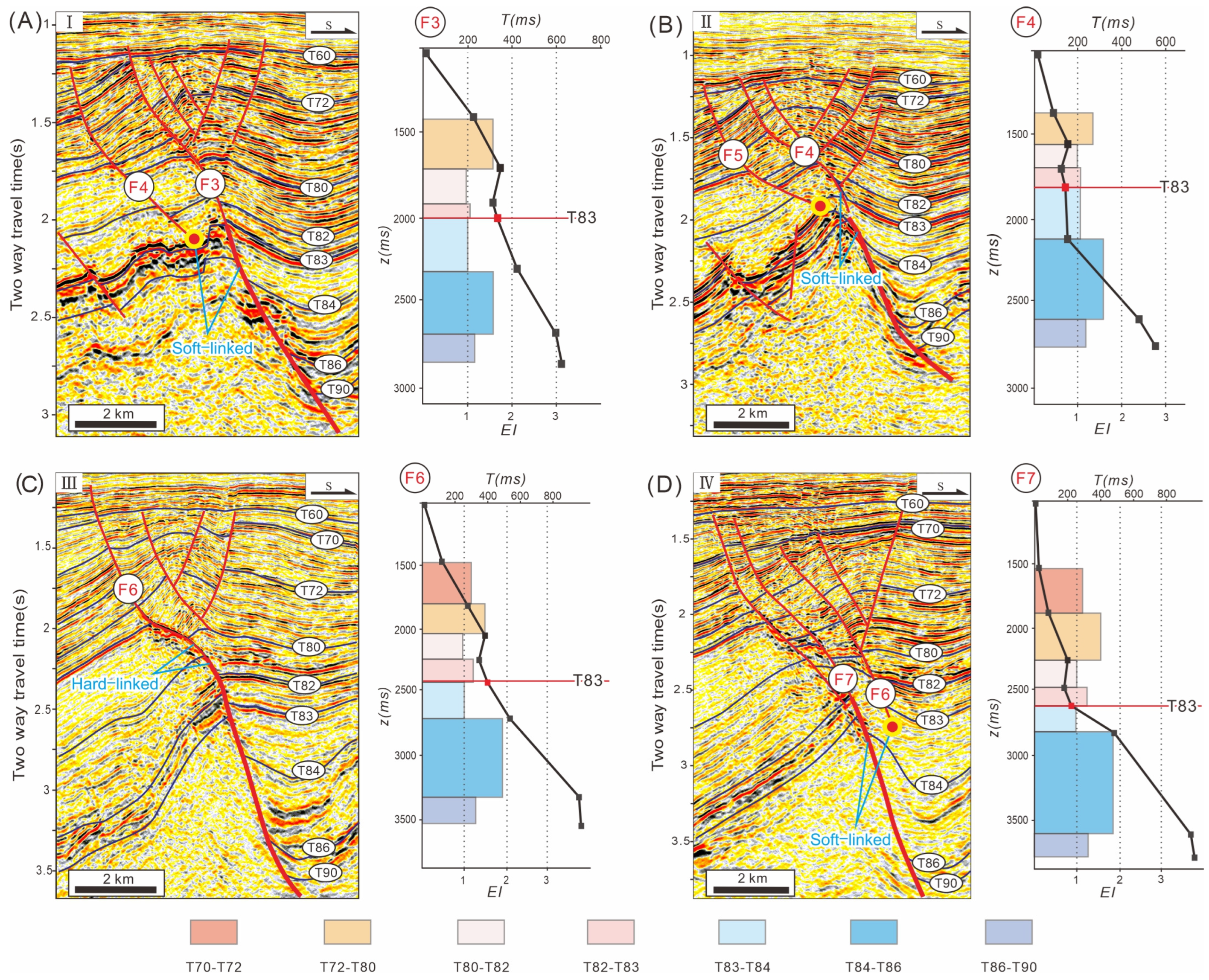
Fault linkage stage—there was propagation, expansion, and linkage of the cap faults vertically with the basement faults. Generally, one side of the upper splay faults was hard-linked and the other side was soft-linked. There was a continuous increase in the displacement rate. A combination of the regulating faults developed within the hangingwall and the major faults constituted the top collapse structure.
During the evolution of the No. 2 fault system, the underlying fault exerted significant control. Although there was a decrease in activity of basement faults, the plastic deformation of the overlying strata, which is controlled by the underlying fault, affects the nucleation and rupture of the upper cap fault. The rotation of regional extension stress led to the upper and lower faults forming a non-collinear fault system. The upper faults experienced a downward propagation but lacked direct linkage with the underlying faults on a large scale. Finally, several en-echelon faults with the ramp-flat structures were formed.
It is significant to note that the No. 2 fault system formed within a distinct context, where the properties of the upper and lower strata were different. There was a shift in lithology from a large set of mudstones in Ls2 to a sand-mud interlayer in Ls1. All the upper splay segments of the No. 2 fault system, which were not strongly linked with the lower basement fault, terminated in the mudstones of Ls2. The flat plane that formed between the upper and lower strata was related to the retarding effect of the plastic mudstone layer. Additionally, the fault dip angle along the strike also exhibited a strong correlation with the strata lithology and properties [21,61].

6. Implications for the Paleogene Depositional Hiatus in the South China Sea

During the evolution of the Paleogene Weixinan Depression, the distribution and structural styles of fault systems exhibited directional and periodic variations. The No. 1 and No. 2 fault systems formed against the background of regional extensional stress exhibiting clockwise rotation. In the Eocene (~40 Ma), the depression-controlling No. 1 fault system started developing under NW–SE extensional stress and the lake basin experienced a transition from expansion to peak. In the late mid-Eocene, the movement of the Indochina Block induced by the Indian-Eurasian collision resulted in the clockwise rotation of regional stress. The basin entered the extension-transtensional stage. Considering both the fault and thickness characteristics of the Weixinan Depression, the evolution of the fault systems in the Weixinan Depression can be divided into the following four stages (Figure 8):
(1)
Initial extension stage in Ls3—No. 1 boundary fault system started developing at a low activity rate. Generally, there is thin deposition with a relatively low subsidence rate. The internal faults, including the No. 2 fault system in the Weixinan Depression, exhibited low fault activity. This stage corresponded to the initial rifting period of the continental faulted basin (Figure 8A);
(2)
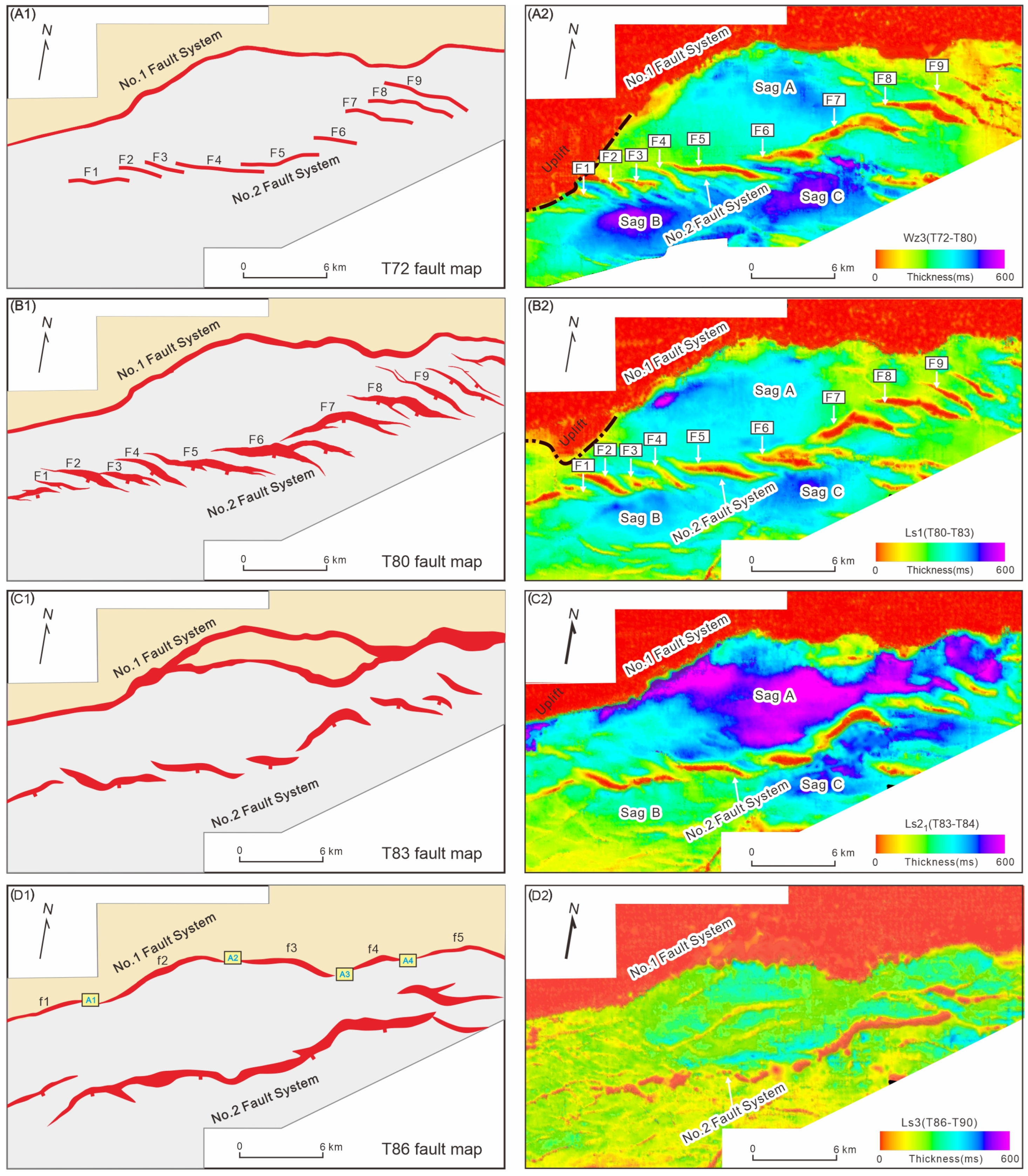
Rapid extension period in Ls2—there was a significant increase in the fault activity of boundary No. 1, as well as a rapid expansion in the lake basin during this stage. In the lower Ls2 stage, the activity rate within the middle part of the boundary No. 1 fault was greater than that on the two sides. Similarly, the thickness center was formed within the middle part of the hangingwall of the No. 1 fault system. The internal normal faults indicated by the No. 2 fault system within the depression were relatively well developed and governed the distribution of local depositional centers (Figure 8B). In the upper Ls2 stage, there was an increase in the overall activity of the No. 1 fault system along the strike. Moreover, the scale of the thickness centers expanded significantly, while the internal normal faults within the depression tended to be static. The No. 1 fault system exerted the strongest influence on depression control during the second period (Figure 8C);
(3)
Extension-transtensional transition stage in Ls1—the activity of the No. 1 fault system continued to weaken during this late rifting stage. The influence of the regional stress rotation led to the activation of the No. 2 fault system, resulting in the migration of depocenters to the depression center. The upper cap faults were relatively underdeveloped and the thickness center was small during this transition period (Figure 8D);
(4)
Transtensional development stage in the Wz Fm—during this stage, there was a continuous increase in the activity of the No. 2 fault system. The thickness center expanded significantly and the scale of the northern depression zone experienced a continuous decrease with the regulation of southern reverse faults. Several cap faults developed at this stage. Due to the retarding effect of the thick plastic mudstone in Ls2, most of the listric faults terminated in the Ls2 sequence (Figure 8E,F).

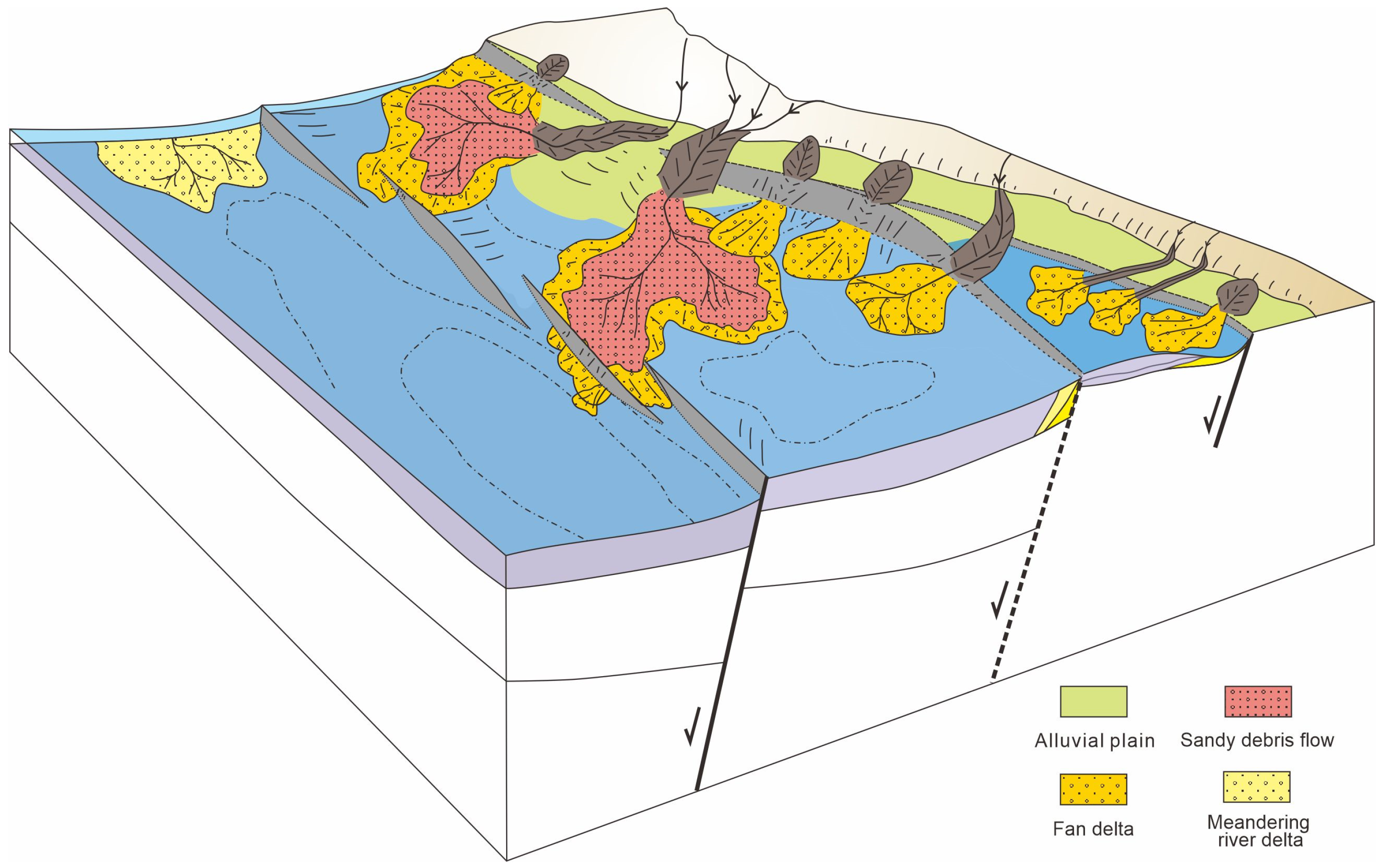
7. Control of the Extensional Fault System on Syn-Rift Sedimentation

7.1. Fan Delta Deposition Controlled by the No. 1 Boundary Fault System

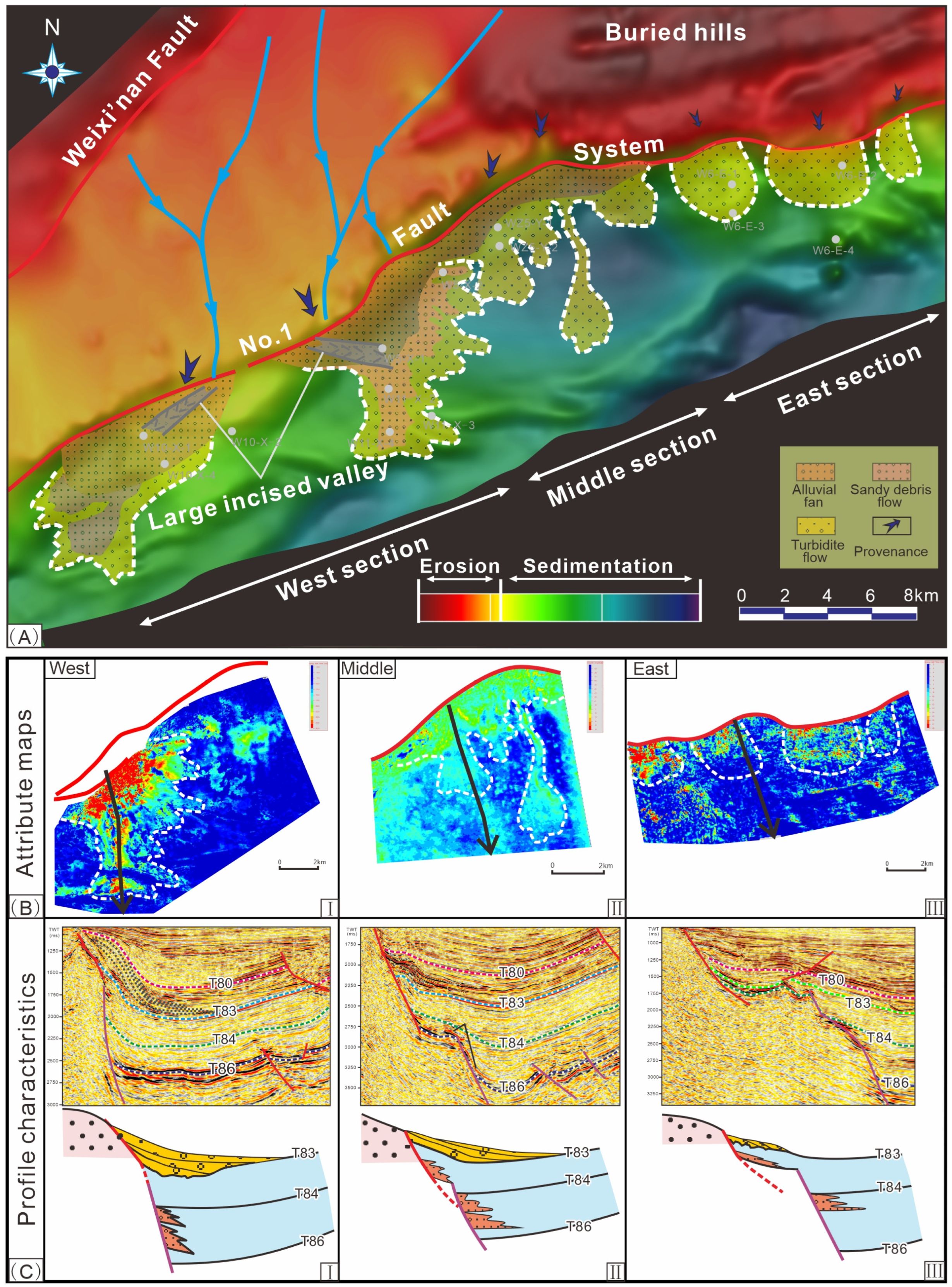
7.1.1. Spatial Distribution Characteristics of Fan Deltas

Based on the seismic attributes and profiles, the distribution characteristics of fan deltas are depicted. Fan delta-gravity flow deposition developed in the hangingwall of the No. 1 boundary fault system in the early Ls1 stage, showing obvious distinctions along the strike.
In the western section, the fan body is large and asymmetrical in the seismic planar attribute map, radiating toward the center of the depression (Figure 9B(I)). The main progradation direction is SSE-oriented, with an area of approximately 45 km2 and a thickness of 150 m. A main channel may have formed in the fan delta as the positive maximum amplitudes increased. Oblique progradational reflections downlapping on the bottom interface T83 are observed on the dip seismic profiles (Figure 9C(I)). Due to the existence of the transverse anticline, the river system in the source area of the western section is concentrated and the sediment supply is sufficient. Rivers flow into the lake basin through the transverse anticline of the western section of the No. 1 fault. The sedimentary body is large in scale and is characterized by strong progradation. The fan delta advances toward the center of the depression with large asymmetric lobes (Figure 9A).
In the middle section, the overall scale of the fan deltas is small. Many branches developed with the main body distributed in the N-S direction. The size of the single branch fan is approximately 10~20 km2, with a thickness of 60 m. Lobes with small narrow channels are observed in the seismic planar attribute map (Figure 9B(II)). There is no obvious progradation in the dip seismic section. The fault slope foot shows strong amplitude reflection, gradually thinning into the basin (Figure 9C(II)). The source area has a high uplift and insufficient sediment supply, resulting in a small fan size. However, the lake basin had a relatively high subsidence rate during the Ls1 stage and the accumulation mode was mainly small-scale progradation and accretion. Small channels were developed, which mainly manifested as gravity flow sedimentation systems (including sandy debris flows and turbidity currents; Figure 9A).
In the eastern section, the overall scale of fan deltas is also small. Lobes are symmetrical in the seismic planar attribute map (Figure 9B(III)). In the dip seismic section, the fan body overlies the bedrock terrace. The amplitude is medium-strong and the continuity is poor (Figure 9C(III)). The sediment supply is insufficient and the fan body is small in scale. The main sand body is deposited at the root of the fault due to the relatively flat paleogeomorphology and erosion gullies (Figure 9A).

7.1.2. Effects of the No. 1 Boundary Fault System on the Differential Development of Steep Slope Fans

The main fault activity generally controls the spatial distribution characteristics of steep slope fans by influencing the ancient geomorphology and accommodation space. The growth and linkage of fault segments control the development of topographic slopes, transition zones, transverse anticlines, and related fault troughs and gullies in steep slope zones. Transition zones, transverse anticlines, gullies, and fault troughs control the formation of sediment transport channels and large sedimentary bodies, while topographic slopes play an important role in controlling sedimentary types (deltas and gravity flows) [4,10,12,62].
During the activity of boundary faults, the subsidence rate of the lake basin varies greatly, is highest in the middle part of the fault, and decreases to both sides. Therefore, in the fault strike section, the strata in the descending wall of the fault, that is, the catchment area, show obvious characteristics of an uplift–depression interphase (Figure 9 and Figure 10). The middle part of the fault features a synclinal topography with a large stratum thickness and low terrain. The two sides of the fault develop anticlines with decreasing stratum thickness. The tilting of the upwelling wall away from the depression often restricts large rivers in the catchment basin from flowing directly into the depression. Instead, they drive large rivers to bypass the upwelling wall and enter the depression along the long axis through the fault ends. The anticlinal plateau on the side of the boundary fault, as the source injection point, has a larger catchment area than that in the middle part of the fault and the sedimentary supply rate is higher than that in the middle part of the fault. A large fan delta and gravity flow sedimentary system was developed on the west side of the fault. A series of small fan bodies were developed in the syncline part of the middle part of the fault. Due to the weak source-supply capacity, the fan deltas transitioned into deeper lacustrine mudstone deposits. In the eastern section of the No. 1 fault, the development of buried carbonate hills decreased the sediment supply.
Overall, the transverse anticline controlled the development of large-scale fan deltas in the western section of the No. 1 fault system. A series of small gully channels that formed in the middle and eastern sections of the No. 1 fault system contributed to the development of small fan bodies. The high subsidence rate in the middle section promoted the development of turbidite fans.

7.2. Axial Meandering River Delta Deposition Controlled by the No. 2 Fault System

The axial sedimentary supply usually occurs in the middle and late stages of rift basin evolution and a large delta-gravity flow sedimentary system is usually formed, which has an important influence on basin-filling succession [63,64]. Strong sedimentary supplies and broad catchments are necessary conditions for the development of axial sedimentary systems [63,65,66].

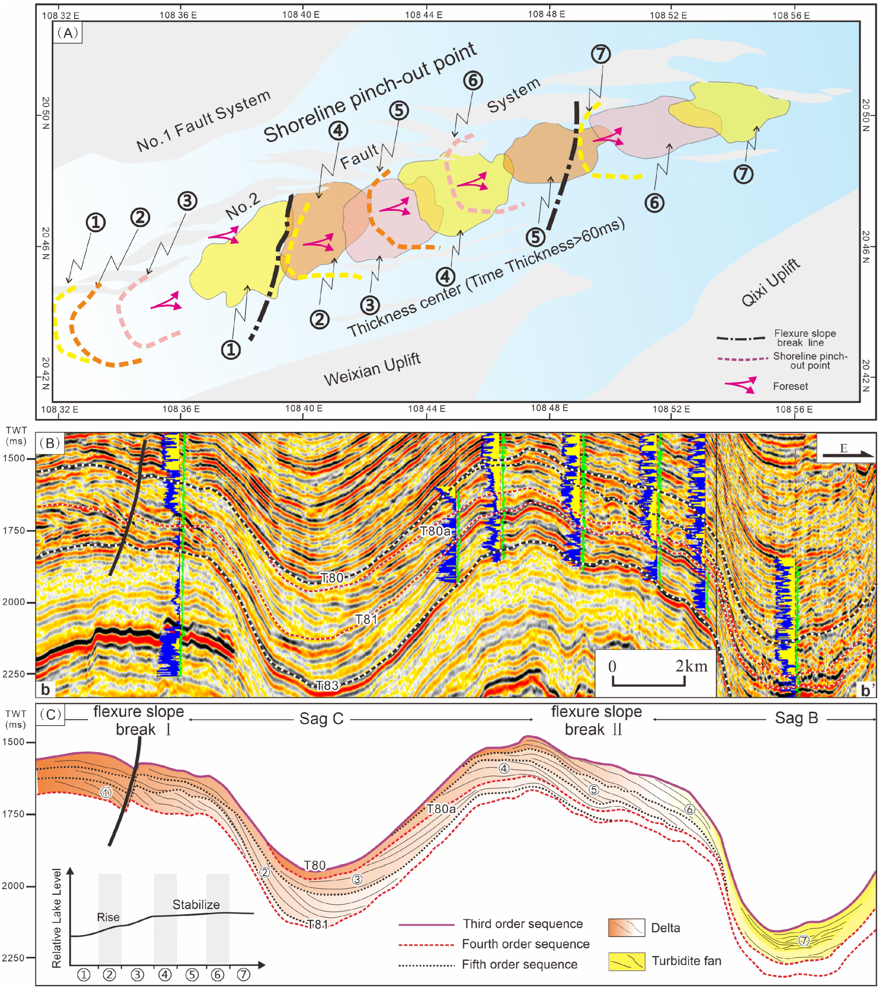
7.2.1. The Division and Distribution of Axial Meandering River Delta Deposition

From the seismic section, a large progradation body is observed along the strike of the No. 2 fault system, extending from the western edge of the depression to the center of the depression (Figure 11A,B). Based on the characteristics of stratigraphic superposition (aggradation and progradation types) and logging cycles, the axial depositional system can be divided into seven stages, including six meandering river deltas and one turbidite (Figure 11C). Among the seven meandering river delta-turbidite systems, the first three lobes (①, ②, and ③) are composed of aggradational parasequence sets. The last four lobes (④, ⑤, ⑥, and ⑦) are classified as progradational parasequence sets. Under the background that the relative lake level shows a rising-stable interaction, the western meandering fan delta with a stable sedimentary supply continues to advance toward the sag along the long axis direction, forming a large axial sedimentary system (Figure 11C).

7.2.2. Effects of the No. 2 Fault System on Axial Meandering River Delta Deposition

During the Ls1 stage, the differential activity along the strike of the No. 2 fault system formed a series of sags on its hangingwall and the overall topographic gradient decreased toward the basin center. The differential subsidence effect leads to an elevation difference between the sags. The accommodation space increases gradually toward the basin center, with the maximum accommodation space occurring in Sag B. In this case, most of the sediments can be exported to low-lying sags, providing favorable conditions for the development of axial sedimentary systems. The axial water system was initially formed at the edge of the basin and was strengthened by the influence of the inclined provenance on both sides. Due to the relatively low accommodation space in the upper reaches, the sags in the upper reaches were quickly filled into an open system, which in turn contributed to the formation of a large catchment basin. Then, more sediments were transported to closed sags downstream. During this period, the sedimentary facies of the sags upstream were fluvial deposits. The axial sedimentary supply is equal to the sum of the axial and inclined sedimentary supplies of the previous sags and the axial sediment supply gradually increases.

8. Conclusions

Well-constrained 3D seismic data from the Weixinan Depression, Beibuwan Basin, and northern South China Sea were employed to elucidate the characteristics and formation mechanisms of the No. 1 and No. 2 fault systems, as well as their effects on syn-rift sedimentation. The following are the major conclusions drawn from this study:
  • The deposition of the lower structural layer of the Liushagang Formation in the Weixinan Depression was governed by the No. 1 boundary fault system. The depocenters are located in the hangingwall of the No. 1 fault system. The evolution of the No. 1 fault system followed the isolated fault model, including the five initial isolated fault segments in the Ls3 stage, the interaction and propagation stage in the lower Ls2, the linkage stage in the upper Ls2, and the decline stage;
  • The No. 2 fault system governs the sedimentation of the upper structural layer of the Liushagang Formation in the Weixinan Depression. Subsequently, the depocenters migrated to the hangingwall of the No. 2 fault system. The oblique reactivation of the No. 2 fault system intersecting the basement fault resulted in sequentially aligned en echelon splay faults in the upper succession. These splay faults rapidly extended during the Ls1 stage and maintained a constant length but were loosely connected during the subsequent displacement process in the Weizhou Formation;
  • The activity of the No. 1 boundary fault and its related fold system contributed to the differential development of the western, middle, and eastern sections of steep slope fans. The fan delta in the western section of the steep slope has a relatively large distribution scale and is asymmetric, characterized by coarse-grained fan delta deposition. A small fan body with a narrow channel developed in the middle section of the steep slope due to turbidity current deposition, which was dominated by a suspended load. In the eastern section, a series of small symmetrical valley channels are observed;
  • The differential subsidence effect of the No. 2 fault system controlled the deposition of axial meandering river deltas and turbidites. The axial depositional system can be divided into seven stages, with the first six stages involving a meandering river delta and the last stage involving a turbidite. The first three lobes are composed of aggradational parasequence sets and the last four lobes are classified as progradational parasequence sets;
  • The growth and linkage of the No. 1 and No. 2 fault systems and controls on syn-rift sedimentation provide useful models for understanding the evolution of the Weixinan Depression and may be used elsewhere to explain the geological history of rift basins with similar settings, as well as the potential for hydrocarbon production.

Supplementary Materials

The following supporting information can be downloaded at: https://www.mdpi.com/article/10.3390/jmse12081392/s1, Figure S1: Uninterpreted seismic profile of Figure 1D; Figure S2: Uninterpreted seismic profile of Figure 3D; Figure S3: Uninterpreted seismic profile of Figure 4; Figure S4: Uninterpreted seismic profile of Figure 6; Figure S5: Uninterpreted seismic profile of Figure 9C; Figure S6: Uninterpreted seismic profile of Figure 11B.

Author Contributions

Conceptualization, J.H. and Y.L.; methodology, J.H.; software, J.H.; validation, T.J., E.L. and S.C.; formal analysis, S.C.; investigation, E.L.; resources, H.W.; data curation, T.J.; writing—original draft preparation, J.H.; writing—review and editing, C.Q.; visualization, S.C.; supervision, Y.L.; project administration, H.W.; funding acquisition, J.H., T.J., E.L. and H.W. All authors have read and agreed to the published version of the manuscript.

Funding

This study was supported by the National Natural Science Foundation of China (42202119, U19B2007, 41976073, and 42072142), Major National Science and Technology Programs in the “Thirteenth Five-Year” Plan period (No. 2016ZX05024-006-002), Postdoctoral Innovation Research Position in Hubei Province (No. 294770), the Zhanjiang Branch of China National Offshore Oil Corporation, and CNOOC South China Sea Oil and Gas Energy Academician Workstation (No. YSPTZX202302).

Institutional Review Board Statement

Not applicable.

Informed Consent Statement

Not applicable.

Data Availability Statement

Uninterpreted seismic reflection profiles are available as supplementary data. The accessibility of seismic data is restricted by commercial, industry, and government policies. The seismic data are owned by the China National Offshore Oil Corporation.

Acknowledgments

We appreciate Zhanjiang Branch Company of China Offshore Oil Corporation for providing the data and permission to publish this paper. We are also very grateful to the reviewers and editors for their contributions to improving this paper.

Conflicts of Interest

Author Chunyu Qin was employed by the Southern Exploration and Development Company. The remaining authors declare that the research was conducted in the absence of any commercial or financial relationships that could be construed as a potential conflict of interest.

References

  1. Jackson, C.A.L.; Gawthorpe, R.L.; Sharp, I.R. Growth and linkage of the East Tanka fault zone, Suez rift: Structural style and syn-rift stratigraphic response. J. Geol. Soc. 2002, 159, 175–187. [Google Scholar] [CrossRef]
  2. Young, M.J.; Gawthorpe, R.L.; Hardy, S. Growth and linkage of a segmented normal fault zone; the late jurassic murchison-statfjord north fault, northern North Sea. J. Struct. Geol. 2001, 23, 1933–1952. [Google Scholar] [CrossRef]
  3. Young, M.J.; Gawthorpe, R.L.; Sharp, I.R. Normal fault growth and early syn-rift sedimentology and sequence stratigraphy: Thal Fault, Suez Rift, Egypt. Basin Res. 2003, 15, 479–502. [Google Scholar] [CrossRef]
  4. Wang, R.; Shi, W.; Xie, X.; Tang, D.; Manger, W.; Busbey, A.B.; Xu, L. Boundary fault linkage and its effect on Upper Jurassic to Lower Cretaceous sedimentation in the Gudian half-graben, Songliao Basin, northeastern China. Mar. Pet. Geol. 2018, 98, 33–49. [Google Scholar] [CrossRef]
  5. Deng, H.; McClay, K. Development of extensional fault and fold system: Insights from 3D seismic interpretation of the Enderby Terrace, NW Shelf of Australia. Mar. Pet. Geol. 2019, 104, 11–28. [Google Scholar] [CrossRef]
  6. Dasgupta, S.; Mukherjee, S.; Vanik, N.; Chatterjee, R.; Pal, S.K. Paleostress analyses and rift kinematics of the petroliferous Barmer rift basin, western Rajasthan, India. Mar. Pet. Geol. 2023, 156, 106442. [Google Scholar] [CrossRef]
  7. Dasgupta, S.; Biswas, M.; Mukherjee, S.; Chatterjee, R. Structural evolution and sediment depositional system along the transform margin-Palar-Pennar basin, Indian east coast. J. Pet. Sci. Eng. 2022, 211, 110155. [Google Scholar] [CrossRef]
  8. Dasgupta, S.; Mukherjee, S. Brittle shear tectonics in a narrow continental rift: Asymmetric non-volcanic Barmer basin (Rajasthan, India). J. Geol. 2017, 125, 561–591. [Google Scholar] [CrossRef]
  9. Trudgill, B.; Cartwright, J. Relay-ramp forms and normal-fault linkages, Canyonlands National park, Utah. Geol. Soc. Am. Bull. 1994, 106, 1143–1157. [Google Scholar] [CrossRef]
  10. Peacock, D.C.P.; Sanderson, D.J. Effects of propagation rate on displacement variations along faults. J. Struct. Geol. 1996, 18, 311–320. [Google Scholar] [CrossRef]
  11. Gupta, S.; Cowie, P.A.; Dawers, N.H.; Underhill, J.R. A mechanism to explain riftbasin subsidence and stratigraphic patterns through fault-array evolution. Geology 1998, 26, 595–598. [Google Scholar] [CrossRef]
  12. Peacock, D.C.P. Propagation, interaction and linkage in normal fault systems. Earth Sci. Rev. 2002, 58, 121–142. [Google Scholar] [CrossRef]
  13. Soliva, R.; Benedicto, A. A linkage criterion for segmented normal faults. J. Struct. Geol. 2004, 26, 2251–2267. [Google Scholar] [CrossRef]
  14. Duffy, O.B.; Bell, R.E.; Jackson, A.L.; Gawthorpe, R.L.; Whipp, P.S. Fault growth and interactions in a multiphase rift fault network: Horda Platform, Norwegian North Sea. J. Struct. Geol. 2015, 80, 99–119. [Google Scholar] [CrossRef]
  15. Liu, Y.; Chen, Q.H.; Wang, X.; Hu, K.; Cao, S.L.; Wu, L.; Gao, F. Influence of normal fault growth and linkage on the evolution of a rift basin: A case from the Gaoyou depression of the Subei Basin, eastern China. AAPG (Am. Assoc. Pet. Geol.) Bull. 2017, 101, 265–288. [Google Scholar] [CrossRef]
  16. Morley, C.K.; Wonganan, N. Normal fault displacement characteristics, with particular reference to synthetic transfer zones, Mae Moh mine, northern Thailand. Basin Res. 2000, 12, 307–327. [Google Scholar] [CrossRef]
  17. Dou, L.R.; Chang, L.A. Fault linkage patterns and their control on the formation of the petroleum systems of the Erlian basin, Eastern China. Mar. Petrol. Geol. 2003, 20, 1213–1224. [Google Scholar] [CrossRef]
  18. Su, J.B.; Zhu, W.B.; Wei, J.; Xu, L.M.; Yang, Y.F.; Wang, Z.Q.; Zhang, Z.Y. Fault growth and linkage: Implications for tectonosedimentary evolution in the chezhen basin of Bohai Bay, eastern China. AAPG (Am. Assoc. Pet. Geol.) Bull. 2011, 95, 1–26. [Google Scholar] [CrossRef]
  19. Xu, Q.H.; Shi, W.Z.; Xie, X.Y.; Busbey, A.B.; Xu, L.T.; Wu, R.; Liu, K. Inversion and propagation of the late paleozoic porjianghaizi fault (north ordos basin, China): Controls on sedimentation and gas accumulations. Mar. Petrol. Geol. 2018, 91, 706–722. [Google Scholar] [CrossRef]
  20. Walsh, J.J.; Bailey, W.R.; Childs, C.; Nicol, A.; Bonson, C.G. Formation of segmented normal faults: A 3-D perspective. J. Struct. Geol. 2003, 25, 1251–1262. [Google Scholar] [CrossRef]
  21. Jackson, C.A.L.; Rotevatn, A. 3D seismic analysis of the structure and evolution of a salt-influenced normal fault zone: A test of competing fault growth models. J. Struct. Geol. 2013, 54, 215–234. [Google Scholar] [CrossRef]
  22. Nicol, A.; Childs, C.; Walsh, J.J.; Manzocchi, T.; Schöpfer, M.P.J. Interactions and growth of faults in an outcrop-scale system. Geol. Soc. Lond. Spec. Publ. 2016, 439, 23–39. [Google Scholar] [CrossRef]
  23. Childs, C.; Holdsworth, R.E.; Jackson, C.A.L.; Manzocchi, T.; Walsh, J.J.; Yielding, G. Introduction to the geometry and growth of normal faults. Geol. Soc. Lond. Spec. Publ. 2017, 439, 1–9. [Google Scholar] [CrossRef]
  24. Jackson, C.A.L.; Bell, R.E.; Rotevatn, A.; Tvedt, A.B.M. Techniques to determine the kinematics of synsedimentary normal faults and implications for fault growth models. J. Geol. Soc. Lond. 2016, 439, 187–217. [Google Scholar] [CrossRef]
  25. Rotevatn, A.; Jackson, C.A.L.; Tvedt, A.B.; Bell, R.E.; Blækkan, I. How do normal faults grow. J. Struct. Geol. 2019, 125, 174–184. [Google Scholar] [CrossRef]
  26. Fu, S.; Liu, Z.; Ge, J.; Tian, N.; Wang, X.; Wang, H.; Liu, H.; Yin, K.; Han, Q. Tectono-stratigraphy characteristics of the Lower Cretaceous Saihantala Sag in the Erlian Basin, China: Normal faulting and controls on the depositional variability. J. Pet. Sci. Eng. 2020, 195, 107840. [Google Scholar] [CrossRef]
  27. Ma, P.; Lin, C.; Ren, L.; Jahren, J.; Dong, D.; Yu, G.; Ma, C.; Wang, D.; Liu, L.; Hellevang, H. Linkage and growth of the independent and coherent faults: Insight into the effect of relay ramps on sedimentation patterns in the northern Bonan Sag, Bohai Bay Basin. Mar. Pet. Geol. 2021, 127, 104985. [Google Scholar] [CrossRef]
  28. Henaish, A.; El Shinawi, A.; Awad, M. Internal architecture and structural evolution of a horst relay zone from the northern Gulf of Suez rift, Egypt: Implications for syn-rift sedimentation. Mar. Pet. Geol. 2023, 150, 106170. [Google Scholar] [CrossRef]
  29. Panpichityota, N.; Morley, C.K.; Ghosh, J. Link between growth faulting and initiation of a mass transport deposit in the northern Taranaki Basin, New Zealand. Basin Res. 2018, 30, 237–248. [Google Scholar] [CrossRef]
  30. Tapponnier, P.; Peltzer, G.; Armijo, R. On the Mechanics of the Collision between India and Asia; Coward, M.P., Ries, A.C., Eds.; Geological Society: London, UK, 1986; Volume 19, pp. 115–157. [Google Scholar]
  31. Hall, R. Cainozoic geological and plate tectonic evolution of SE Asia and the SW Pacific: Computer-based reconstructions, model and animations. J. Asian Earth Sci. 2002, 20, 353–431. [Google Scholar] [CrossRef]
  32. Morley, C.K. Discussion of tectonic models for Cenozoic strike-slip fault-affected continental margins of mainland SE Asia. J. Asian Earth Sci. 2013, 76, 137–151. [Google Scholar] [CrossRef]
  33. Fyhn, M.B.; Cuong, T.D.; Hoang, B.H.; Hovikoski, J.; Olivarius, M.; Tuan, N.Q.; Tung, N.T.; Huyen, N.T.; Cuong, T.X.; Nytoft, H.P.; et al. Linking Paleogene rifting and inversion in the northern Song Hong and Beibuwan basins, Vietnam, with left-lateral motion on the Ailao Shan-Red River shear zone. Tectonics 2018, 37, 2559–2585. [Google Scholar] [CrossRef]
  34. Cheng, S.X.; Li, S.Z.; Suo, Y.H.; Liu, X.; Yu, S.; Dai, L.M.; Ma, Y.; Zhao, S.J.; Wang, X.F.; An, H.T.; et al. Cenozoic tectonics and dynamics of basin groups of the northern South China Sea. Mar. Geol. Quat. Geol. 2013, 32, 80–93. [Google Scholar] [CrossRef]
  35. Wang, J.; Cao, Y.; Li, J. Sequence structure and non-structural traps of the Paleogene in the weixinan sag, Beibuwan Basin. Petrol. Explor. Dev. 2012, 39, 325–334. [Google Scholar] [CrossRef]
  36. Liu, E.; Wang, H.; Li, Y.; Zhou, W.; Leonard, N.D.; Lin, Z.; Ma, Q. Sedimentary characteristics and tectonic setting of sublacustrine fans in a half-graben rift depression, Beibuwan Basin, South China Sea. Mar. Pet. Geol. 2014, 52, 9–21. [Google Scholar] [CrossRef]
  37. Liu, E.; Uysal, I.T.; Wang, H.; Feng, Y.; Pan, S.; Yan, D.; Nguyen, A.D.; Zhao, J.X. Timing and characterization of multiple fluid flow events in the Beibuwan Basin, northern South China Sea: Implications for hydrocarbon maturation. Mar. Pet. Geol. 2021, 123, 104754. [Google Scholar] [CrossRef]
  38. Li, Y.; Zhao, Y.; Lin, Z.; Ma, Q. Tectonic characteristics and structural styles of a continental rifted basin: Revelation from deep seismic reflection profiles. Geod. Geodyn. 2016, 7, 329–339. [Google Scholar] [CrossRef]
  39. Zhao, Y.; Wang, H.; Yan, D.; Jiang, P.; Chen, S.; Zhou, J.; Ma, J.; Qin, C.; He, J.; Zhao, Y. Sedimentary characteristics and model of gravity flows in the eocene Liushagang Formation in Weixi’nan depression, South China Sea. J. Pet. Sci. Eng. 2020, 190, 107082. [Google Scholar] [CrossRef]
  40. Liu, E.; Wang, H.; Pan, S.; Qin, C.; Jiang, P.; Chen, S.; Yan, D.; Lü, X.; Jing, Z. Architecture and depositional processes of sublacustrine fan systems in structurally active settings: An example from Weixinan Depression, northern South China Sea. Mar. Pet. Geol. 2021, 134, 105380. [Google Scholar] [CrossRef]
  41. Cao, L.; Zhang, Z.; Li, H.; Zhong, N.; Xiao, L.; Jin, X.; Li, H. Mechanism for the enrichment of organic matter in the Liushagang Formation of the Weixinan Sag, Beibuwan Basin, China. Mar. Pet. Geol. 2020, 122, 104649. [Google Scholar] [CrossRef]
  42. Gong, Y.; Pease, V.; Wang, H.; Gan, H.; Liu, E.; Ma, Q.; Zhao, S.; He, J. Insights into evolution of a rift basin: Provenance of the middle Eocene-lower Oligocene strata of the Beibuwan Basin, South China Sea from detrital zircon. Sediment. Geol. 2021, 419, 105908. [Google Scholar] [CrossRef]
  43. Gan, H.; Gong, S.; Tian, H.; Wang, H.; Chen, J.; Ma, Q.; Liu, K.; Lv, Z. Geochemical characteristics of inclusion oils and charge history in the Fushan Sag, Beibuwan Basin, South China Sea. Appl. Geochem. 2023, 150, 105598. [Google Scholar] [CrossRef]
  44. Wang, X.; Li, M.; Yang, T.; Zeng, B.; Shi, Y.; Liu, X.; Tang, Y. Identification, distribution and geochemical significance of benzo [b] naphthofurans and benzo [b] naphthothiophenes in source rocks from the Beibuwan Basin, South China Sea. Chem. Geol. 2023, 626, 121454. [Google Scholar] [CrossRef]
  45. Wang, L.; Lei, X.; Zhang, Q.L.; Yao, G.Q.; Sui, B.; Chen, X.J.; Wang, M.W.; Zhou, Z.Y.; Wang, P.R.; Peng, X.D. Experimental study of the effects of a multistage pore-throat structure on the seepage characteristics of sandstones in the Beibuwan Basin: Insights into the flooding mode. Pet. Sci. 2024, 21, 1044–1061. [Google Scholar] [CrossRef]
  46. Huang, B.; Zhu, W.; Tian, H.; Jin, Q.; Xiao, X.; Hu, C. Characterization of Eocene lacustrine source rocks and their oils in the Beibuwan Basin, offshore South China Sea. AAPG Bull. 2017, 101, 1395–1423. [Google Scholar] [CrossRef]
  47. Huang, B.; Tian, H.; Wilkins, R.W.T.; Xiao, X.; Li, L. Geochemical characteristics, palaeoenvironment and formation model of Eocene organic-rich shales in the Beibuwan Basin. South China Sea. Mar. Petrol. Geol. 2013, 48, 77–89. [Google Scholar] [CrossRef]
  48. Zhu, W.L.; Wu, G.X. Palaeolimology and hydrocarbon potential in Beibuwan Basin of the South China Sea. Oceanol. Limnol. Sin. 2004, 35, 8–14, (In Chinese with English abstract). [Google Scholar]
  49. Cheng, Y.; Wu, Z.; Zhang, J.; Liu, Y.; Wang, Z.; Dai, Y. Cenozoic rifting and inversion of Beibuwan Basin and its linkage with the strike-slip movement along the Ailao Shan-Red River Shear Zone. Int. Geol. Rev. 2022, 64, 2966–2983. [Google Scholar] [CrossRef]
  50. Guo, L.L.; Li, S.Z.; Zhao, S.J.; Zhang, G.X.; Suo, Y.H.; Liu, H.; Li, X.Y. Final breakup of continental block and opening of oceanic lithosphere: Insights from deep crustal structure and tectonic evolution of the ocean–continent transition zone in the northern South China Sea. Geol. J. 2016, 51, 318–330. [Google Scholar] [CrossRef]
  51. Catuneanu, O. Principles of Sequence Stratigraphy; Elsevier: Amsterdam, The Netherlands, 2006; p. 375. [Google Scholar]
  52. Catuneanu, O. Scale in sequence stratigraphy. Mar. Pet. Geol. 2019, 106, 128–159. [Google Scholar] [CrossRef]
  53. Misra, A.A.; Mukherjee, S. Atlas of Structural Geological Interpretation from Seismic Images; Wiley Blackwell: Hoboken, NJ, USA, 2018; ISBN 978-1-119-15832-5. [Google Scholar]
  54. Bell, R.E.; Jackson, C.A.L.; Whipp, P.S.; Clements, B. Strain migration during multiphase extension: Observations from the northern North Sea. Tectonics 2014, 33, 1936–1963. [Google Scholar] [CrossRef]
  55. Zhang, M.; Waldron, J.W.; Wu, Z.; Zhang, X. Growth and transtensional reactivation of a basin-bounding fault: Chengbei Sag, Bohai Bay Basin, East China. Tectonophysics 2023, 862, 229937. [Google Scholar] [CrossRef]
  56. Schwartz, D.P.; Coppersmith, K.J. Fault behavior and characteristic earthquakes: Examples from the Wasatch and San Andreas fault zones. J. Geophys. Res. 1984, 89, 5681–5698. [Google Scholar] [CrossRef]
  57. Walsh, J.J.; Watterson, J. Analysis of the relationship between displacements and dimensions of faults. J. Struct. Geol. 1988, 10, 239–247. [Google Scholar] [CrossRef]
  58. Mukherjee, S. Particle tracking in ideal faulted blocks using 3D co-ordinate geometry. Mar. Pet. Geol. 2019, 107, 508–514. [Google Scholar] [CrossRef]
  59. Qin, C. The Paleogene Evolution of Double-Layer Structure and the Response of Sedimentation of Weixi’nan Sag, Beibuwan Basin. Ph.D. Thesis, China University of Geoscience, Wuhan, China, 2021. (In Chinese). [Google Scholar]
  60. Morley, C.K. A tectonic model for the Tertiary evolution of strike-slip faults and rift basins in SE Asia. Tectonophysics 2002, 347, 189–215. [Google Scholar] [CrossRef]
  61. Giba, M.; Walsh, J.J.; Nicol, A. Segmentation and growth of an obliquely reactivated normal fault. J. Struct. Geol. 2012, 39, 253–267. [Google Scholar] [CrossRef]
  62. Deibert, J.E.; Camilleri, P.A. Sedimentologic and tectonic origin of an incisedvalley-fill sequence along an extensional marginal-lacustrine system in the basin and range province, United States: Implications for predictive models of the location of incised valleys. AAPG Bull. 2006, 90, 209–235. [Google Scholar] [CrossRef]
  63. Leeder, M.R.; Mack, G.H. Lateral erosion (‘toe-cutting’) of alluvial fans by axial rivers: Implications for basin analysis and architecture. J. Geol. Soc. 2001, 158, 885–893. [Google Scholar] [CrossRef]
  64. Schuster, M.; Nutz, A. Lacustrine wave-dominated clastic shorelines: Modern to ancient littoral landforms and deposits from the Lake Turkana Basin (East African Rift System, Kenya). J. Paleolimnol. 2018, 59, 221–243. [Google Scholar] [CrossRef]
  65. Lambiase, J.J. A model for tectonic control of lacustrine stratigraphic sequences in continental rift basins. Am. Assoc. Pet. Geol. 1990, Memoir 50, 265–276. [Google Scholar]
  66. Sztanó, O.; Szafián, P.; Magyar, I.; Horányi, A.; Bada, G.; Hughes, D.W.; Hoyer, D.L.; Wallis, R.J. Aggradation and progradation controlled clinothems and deep-water sand delivery model in the Neogene Lake Pannon, Makó Trough, Pannonian basin, SE Hungary. Glob. Planeary Chang. 2013, 103, 149–167. [Google Scholar] [CrossRef]
Figure 1. (A) Major sedimentary basins in the South China Sea. (B) Simplified structural map indicating the location of Weixinan Depression and other units in the Beibuwan Basin, as shown in (A). (C) Geological map of the Weixinan Depression. (D) Representative seismic profile aa’ perpendicular to the No. 1 and No. 2 fault systems in the Weixinan Depression, respectively. Locations of the profile are shown in (C). The uninterpreted seismic profile is provided in Supplementary Materials Figure S1 [37].
Jmse 12 01392 g001
Figure 2. Stratigraphic framework, sedimentary sequence, and major tectonic stages of the Weixinan Depression, Beibuwan Basin [37].
Jmse 12 01392 g002
Figure 3. (A) Fault map showing the No. 1 fault system at stratigraphic levels of T86. (B) Profiles displaying fault activity rates at the stratigraphic levels of T86, T83, and T80. Four fault segment linkage points A1, A2, A3, and A4 are identified. (C) Fault dip angle profiles at the stratigraphic levels of T86. (D) Seismic cross-sections along the strike of the No. 1 fault system indicate the transverse anticlines formed at the fault segment linkage points. The location of the profile is shown in (A). The uninterpreted seismic profile is provided in Supplementary Materials Figure S2.
Jmse 12 01392 g003
Figure 4. Cross-sections (AF) illustrating the structural configurations of the No. 1 fault system by inline 3130, inline 3660, inline 3880, inline 4490, inline 4770 and inline 5330, respectively (refer to its locations in Figure 3A). The uninterpreted seismic profiles are provided in Supplementary Materials Figure S3.
Jmse 12 01392 g004
Figure 5. (A) Fault map illustrating the splay segmented faults and basement fault of the No. 2 fault system. (BD) Profiles of fault displacement at the T86, T84, and T80 horizons. (E,F) Three-dimensional visualization of the No. 2 fault system.
Jmse 12 01392 g005
Figure 6. Interpreted seismic sections (AD) perpendicular to the No. 2 fault system and their corresponding throw-depth plots. Locations of the sections are shown in Figure 5A. The uninterpreted seismic profiles are provided in Supplementary Materials Figure S4.
Jmse 12 01392 g006
Figure 7. Fault evolution (A1D1) and thickness maps (A2D2) show the spatial and temporal development of the No. 1 and No. 2 fault systems and the migration of depocentres from T86, T83, T80 to T72, respectively.
Jmse 12 01392 g007
Figure 8. Balanced cross section of inline 4491 from Ls3 to present. The approximate location of inline 4491, which is close to inline 4490, is indicated in Figure 3. The percentage values in the top right corner indicated the shortening percentage.
Jmse 12 01392 g008
Figure 9. (A) The superimposed map of the paleogeographic pattern and distribution of fans in the steep slope zone of the Ls1 Formation in the Weixinan Depression. (B) Representative attribute maps of fans in the steep slope zone of the Ls1 Formation in the Weixinan Depression. The arrows indicate the long axis of fans. (C) The seismic characteristics of fans that developed in the western, central, and eastern sections of the steep slope zone of the Ls1 Formation in the Weixinan Depression. The uninterpreted seismic profile are provided in Supplementary Materials Figure S5.
Jmse 12 01392 g009
Figure 10. Depositional model of fans developed in the hangingwall of the No. 1 boundary fault system.
Jmse 12 01392 g010
Figure 11. (A) Plane distribution characteristics of axial meandering river delta-turbidite deposition along the hangingwall of the No. 2 fault system in the Ls1 Weixinan Depression (after [37]). (B,C) Seismic foreset reflection characteristics and stage division of the axial delta system. The uninterpreted seismic profile is provided in Supplementary Materials Figure S6.
Jmse 12 01392 g011
Disclaimer/Publisher’s Note: The statements, opinions and data contained in all publications are solely those of the individual author(s) and contributor(s) and not of MDPI and/or the editor(s). MDPI and/or the editor(s) disclaim responsibility for any injury to people or property resulting from any ideas, methods, instructions or products referred to in the content.

