Article

Wave-Current Interaction Effects on the OC4 DeepCwind Semi-Submersible Floating Offshore Wind Turbine

by
Thomas P. Mazarakos
1,* and
Spyridon A. Mavrakos
2,*
1
Department of Naval Architecture, University of West Attica, 12243 Egaleo, Greece
2
Laboratory for Floating Structures and Mooring Systems, Division of Marine Structures, School of Naval Architecture and Marine Engineering, National Technical University of Athens, 15773 Athens, Greece
*
Authors to whom correspondence should be addressed.
J. Mar. Sci. Eng. 2024, 12(9), 1509; https://doi.org/10.3390/jmse12091509
Submission received: 25 July 2024 / Revised: 21 August 2024 / Accepted: 28 August 2024 / Published: 1 September 2024

Abstract

:
In order to investigate the hydrodynamic performances of semi-submersible type floating offshore wind turbines (FOWTs), particularly the effect of body-wave-current interaction, the OC4 FOWT is considered in the presence of co-existing regular wave and uniform current fields. The wind loads are not considered at this stage. The problem is treated in the framework of potential-flow theory in the frequency domain, assuming waves of small steepness, and the solution is obtained by using a perturbation expansion method for the diffraction potential with respect to the normalized current speed. Analytical and numerical formulations have been used to treat the inhomogeneous free-surface boundary condition involved in the hydrodynamic problem formulation for the derivation of the associated perturbation potential. The hydrodynamic loads were obtained after evaluating the pressure field around the multi-body configuration using three different computer codes. The results from the three computer codes compare very well with each other and with the numerical predictions of other investigators. Finally, the mean second-order drift forces are calculated by superposing their zero-current values with the corresponding current-dependent first-order corrections, with the latter being evaluated using a ‘heuristic’ approach.

1. Introduction

Offshore wind energy is currently attracting most of the research attention within the sector. Most installations presently concern shallow water sites and fixed WT designs, but as substantial wind potential resources are available in the open sea, several floating offshore wind turbine (FOWT) concepts have been proposed as alternatives to bottom-fixed installations representing an important milestone for the wind energy industry [1]. The use of FOWTs in deeper waters is supported by several benefits, such as steadier winds and fewer visual and noise disturbances, which in many cases are prohibitive for land- or nearshore-based WT installations. However, the deployment of FOWT concepts is associated with specific design challenges and analysis methods, especially regarding the floating support structure and its station-keeping system. Several floating concept designs have been presented in the literature, which, according to the terminology used in oil and gas offshore installations, can be classified as spar buoys, semi-submersibles, and TLP platforms. They have been numerically and experimentally investigated by several researchers and research groups; representative results have been reported in the literature, including results on the OC3-Hywind spar buoy [2,3,4], the OC4-DeepCwind semi-submersible platform [5,6,7], and the UMaine TLP [8,9].
The dynamic behavior of a FOWT is crucial for its life-cycle assessment concerning structural integrity, operation, maintenance, LCOE analysis, etc. [10]. It requires a consistent methodology that should account for the coupling of aerodynamics, hydrodynamics, structural elasticity, mooring system behavior, and the control system in the time domain. A frequently utilized time-domain simulation tool for the coupled analysis of FOWT is FAST software [11], which has been developed by NREL. It includes linear wave loads through hydrodynamic coefficients calculated in its HydroDyn module.
However, recent developments in the hydrodynamic modeling of FOWT, originating from experiences from offshore engineering, show the importance of accounting for second-order effects [12,13] when analyzing their dynamics. Second-order wave loads consist of a steady component (mean drift force) and time-dependent sum- and difference-frequency loads that may excite resonant responses of moored structures in cases where the oscillatory frequencies of these second-order time-dependent load components are in the vicinity of the moored floating structure’s natural frequencies. Representative examples are the slow-drift, large-amplitude horizontal motions of compliant floating structures excited by the difference-frequency wave loads and the springing excitation of a TLP platform due to sum-frequency second-order wave loads. The dynamic response analysis of FOWTs by accounting for second-order, sum-, and difference-frequency loads has been reported in the literature for spar buoy-type FOWTs [4,14], semi-submersible floating WTs [15,16], and TLP concepts [14,17,18].
Apart from the second-order hydrodynamic effects that influence the response of a floating marine structure, the body-wave interaction in the presence of a sea current, or equivalently, the investigation of the slow drift motion of a floating structure in the marine environment subjected to surface gravity waves has attracted the attention of the international research community in recent decades, especially in the oil and gas offshore industry, as it might affect critical design parameters of marine structures, such as first- and second-order wave exciting loads imposed on a structure; mean second-order forces (drift forces); second-order wave-drift damping, etc. To the best of our knowledge, the problem of a floating WT interacting in the presence of co-existing wave and current fields has not received much attention from the research community and, thus, relevant results could be considered rather limited.
The combination of sea currents and waves significantly affects the calculation of mean second-order wave-drift loads as well as corresponding second-order wave-drift damping. The omission of the latter may result in an underestimation of the total damping offered to the floating structure and, consequently, lead to the calculation of large and unrealistic displacements, as well as excess loadings in its mooring system.
The literature review on fluid dynamics problems encountered when considering mean and slowly varying second-order drift loads was presented in a series of publications (see, for example, [12,13,19,20,21]) to name a few references.
As far as the body-wave-current interaction is concerned, it has been shown that it cannot be treated as a simple superposition of the loading due to independently acting wave and current fields, as the presence of the current distorts the incident and diffracted wave fields generated around the body and, consequently, the excitation forces and the rest of the hydrodynamic parameters [22,23,24,25]. These problems have been addressed in recent decades when designing floating structures for the oil and gas industry, but with the recent development of offshore wind energy exploitation through FOWTs, they have become of particular interest in the design of these structures as well. In this direction, Ref. [26] investigated the effects of the body-wave-current interaction for a spar buoy-type floater supporting a 6 MW WT. The authors applied a potential-flow theory and perturbation method in conjunction with a cubic boundary element method (BEM) to treat the resulting boundary-value problems up to the second order in the time domain. Recently, the authors of [27], when studying offshore and shoreline protection systems, investigated the structures of the reflected and transmitted 3D wave fields of small steepness when interacting with arrays of vertical cylinders in the presence of currents using a coupled BEM-FEM method to solve the resulting boundary value problems (BVPs).
One approach to solving the body-wave-current interaction problem involves solving it in the frequency domain by introducing two time scales and developing the velocity potential based on the Strouhal number τ = ωU/g, where ω is the encounter frequency, U is the current velocity, and g is the acceleration of gravity [28]. For arbitrarily shaped bodies, the solutions are obtained by solving integral equations for which appropriate Green’s functions are included, considering a small forward velocity or an equivalent current velocity [22,29,30,31,32]. The associated evaluation of the mean second-order wave-drift forces is carried out using two well-known methods: near-field and far-field approaches. The far-field method is based on the principle of conservation of momentum and involves integrating the pressure and velocity components over a far-field control surface. The method was first introduced by Maruo in 1960 [33], who derived the relationship for the added resistance of a ship in waves using the Kochin function. Newman later extended this work to include the zero-speed problem in 1967 [34]. The near-field method involves integrating the pressure and velocity components over the body’s wetted surface and surrounding control surface [35].
The key differences between the near-field and far-field methods for calculating the mean second-order drift wave forces on floating bodies are basically three. Firstly, as presented in the previous paragraph, the formulation. Secondly, the forces are calculated by each method: the far-field method calculates the mean second-order wave-drift forces in the seaplane (surge, sway, yaw) while the near-field method calculates the forces in all six degrees of freedom of motion. Thirdly, the calculation time: the far-field method is compared faster to the near-field method.
Regarding the calculation of the second-order wave-drift damping, one way of calculating it is based on solving the problem of the body-wave-current interaction and calculating the mean second-order wave-drift forces.
The second-order wave-drift damping coefficient can then be calculated by numerical differentiation between the mean second-order wave-drift forces at two small different current velocities. Works were conducted by Refs. [36,37,38,39,40,41,42,43,44].
The wave-current interaction is a critical factor in the dynamic analysis of FOWTs, influencing various aspects such as mean second-order wave-drift loads and wave-drift damping. The effects of wave-current interaction on the structural responses of floating WTs have been the focus of recent research, highlighting the significance of considering these interactions in dynamic analyses.
Additionally, the impact of wave-current interaction on second-order wave-drift loads has been investigated, emphasizing the need to understand and account for this phenomenon in the design of offshore structures, including WTs [45].
By considering the complex interplay between waves and currents, it is possible to gain a comprehensive understanding of the dynamic behavior of FOWT, ultimately contributing to the advancement of offshore wind energy technology [46,47].
In this paper, we delve into the implications of wave-current interaction on mean second-order wave-drift forces and wave-drift damping in the context of FOWTs, using the OC4 DeepCwind FOWT as a paradigm to provide valuable insights into this significant aspect of floating WT dynamics.
This paper is organized as follows: In Section 2, we describe the free-floating platform’s geometry. Next, in Section 3, we proceed to the formulation and solution of the hydrodynamic problem with in-house and commercial codes, while in Section 4, we present the numerical results for the first-order loads acting on the structure, added masses, damping coefficients, RAOs of motion of the floating platform, the mean second-order wave-drift loads, and the wave-drift damping, with and without current. Finally, the major conclusions are drawn in Section 5.

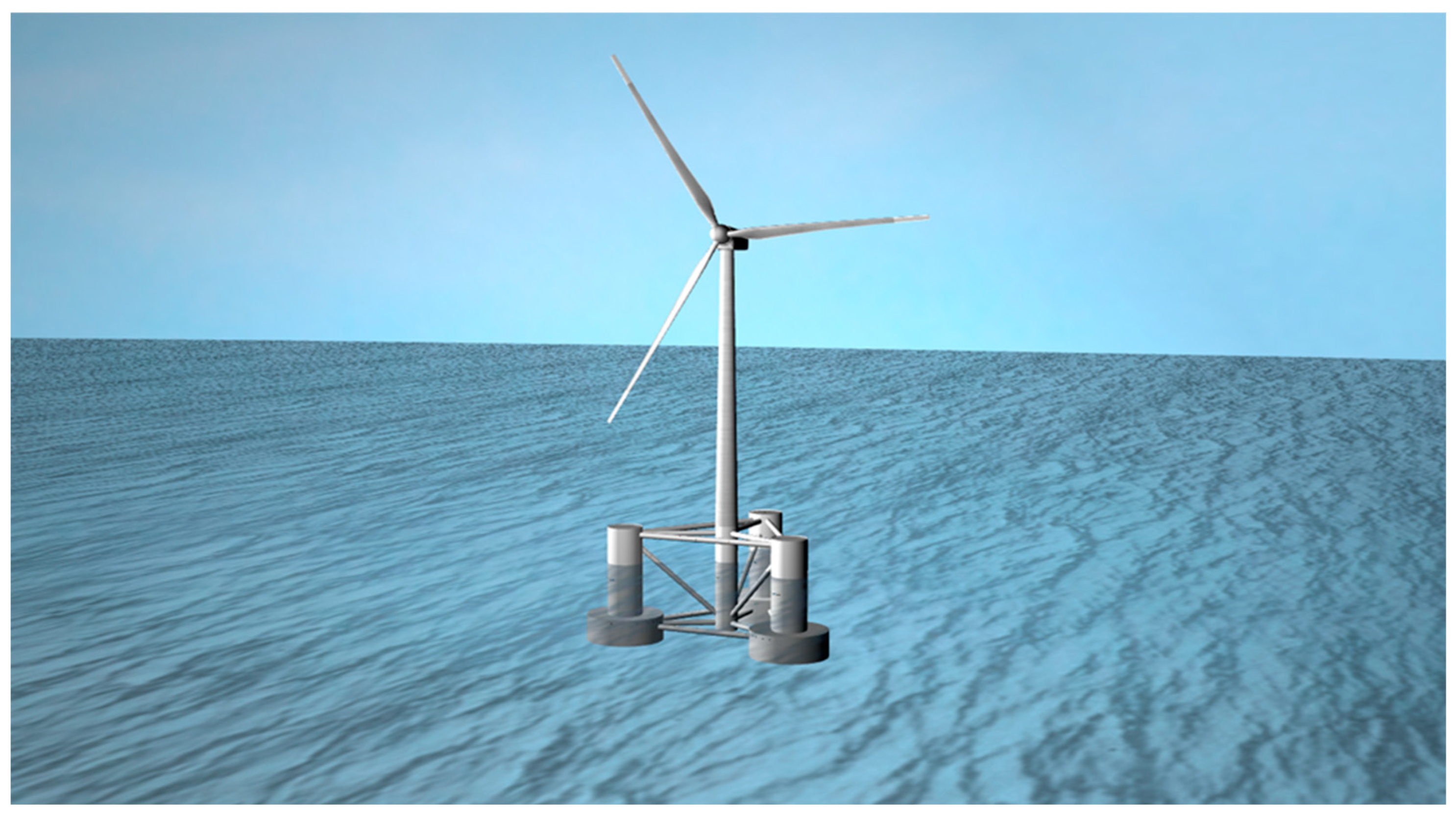
2. The OC4 Semisubmersible Platform Geometry

The floating semi-submersible structure consists of the central support pylon for the 5 MW WT with a diameter of 6.25 m. The three peripheral cylinders are compound vertical cylindrical bodies where the upper one has a diameter of 12 m and the lower one has a diameter of 24 m. The height of the upper vertical cylindrical body is 14 m and the lower one is 6 m. The peripheral cylinders form an equilateral triangle with sides of 50 m. The draft of the semi-submerged structure is 20 m and the depth of the installation area is 200 m (Figure 1).
The mass of the floating semi-submersible structure is 13,473 t, the center of mass is located at 13.46 m below the still water level, the roll and pitch inertias of the structure about the still water level are 9,267,925 tm2, and the yaw inertia is 12,260,000 tm2. More details can be found in [6].

3. Solution of the Hydrodynamic Problem

3.1. Wave-Structure Solution

3.1.1. The In-House Code HAMVAB

The in-house code HAMVAB was developed in Fortran to conduct hydrodynamic analysis (solution of the diffraction and radiation problems) specifically tailored for multi-cylindrical axisymmetric bodies with vertical symmetry axis. This code offers a comprehensive solution for studying the fluid dynamics around such structures, providing valuable insights into their behavior in various flow conditions. Its specialized algorithms enable engineers and researchers to accurately predict the performance of cylindrical axisymmetric bodies in fluid environments. Its efficient calculations and detailed output make it a valuable asset for those involved in marine engineering, offshore structures, and other related fields requiring precise hydrodynamic analysis. The code provides detailed numerical results for the hydrodynamic behavior of floating bodies as first-order wave forces, hydrodynamic masses, damping coefficients, motion responses, and mean second-order wave-drift forces. The solution algorithm employed is based on single-body hydrodynamic characteristics that are properly combined through the concept of multiple scattering [21,48,49] to account for the hydrodynamic interaction effects within the multi-body arrangement. The single-body hydrodynamic characteristics are evaluated using matched axisymmetric eigenfunction expansions for the velocity potential around the body in the form of the Fourier–Bessel series expressed in the cylindrical coordinate system [50].

3.1.2. The In-House Code HAQi

The in-house code HAQi was developed in Fortran to conduct hydrodynamic analysis (solutions of the diffraction and radiation problems) of arbitrarily shaped large bodies. This code is particularly useful for studying the fluid dynamics around structures, such as those found in offshore engineering. HAQi employs advanced numerical methods and algorithms to accurately predict the hydrodynamic behavior of large bodies in various flow conditions. Its capabilities extend to analyzing the hydrodynamic characteristics of single- or multi-body complex geometries, providing valuable insights into optimizing the design and performance of these structures. The code provides detailed numerical results for the hydrodynamic behavior of floating bodies as first-order wave forces, hydrodynamic masses, damping, motion responses, and mean second-order wave-drift forces using both direct integration of all second-order pressure contributions on the wetted surface of the body, as well as the momentum conservation principle. HAQi is a numerical solver designed to treat the potential flow body-wave interaction problem utilizing pulsating sink sources distributed on the wetted surface of the body for the integral equation representation of the flow field around the body [51]. The 3D formulation of the pulsating source for the finite water depth case used in HAQi is described in detail in [52]. To fulfill the boundary conditions on the wetted surface of the body, the latter is subdivided into plane facets of triangular or quadrilateral shapes with singularities concentrated at the center of each facet and, thus, the integral equation representation of the flow field around the body is replaced by a sum of integrals extending over each facet, which are evaluated numerically.

3.2. Wave and Current Solution

3.2.1. First-Order Loads

For the solution to the wave-current problem, the total fluid potential is as follows [53]:
Φ x , y , z ; t = H 2 φ x , y , z e i ω w c t
where
ω w c = ω k U c o s β
with k: wave number, ω : wave frequency,   ω w c : wave and current frequency, U : current velocity (steady current), and β: angle between wave and current.
The potential function is calculated by solving the Laplace equation, applying appropriate boundary conditions, and then calculating the pressure and forces acting on the structure. Based on the Bernoulli equation, the wave exciting forces/ moments are as follows:
F j = ρ S 0 i ω w c + U φ x , y , z n j d S
For j = 1, 2, 3 ( F 1 ,   F 2 ,   F 3   o r   F x ,   F y ,   F z ), the excitation forces are calculated, and for j = 4, 5, 6 ( F 4 ,   F 5 ,   F 6   o r   M x ,   M y ,   M z ), the excitation moments are calculated, respectively.
The added mass and the hydrodynamic damping are written as follows:
A i j + 1 ω w c B i j = i ρ ω w c S 0 n j + i ω w c U n j φ r i x , y , z d S
For the solution of the hydrodynamic problem the frequency domain pulsating Green’s function is used [53].
The response amplitude operators (RAOs) of the motion are obtained as follows:
[ ω w c 2 Μ + A i j ω w c B i j + C h y d r o ]   x j 0 = F j
where Μ is the generalized mass matrix of the structure, A i j , B i j are the added mass and hydrodynamic damping matrixes respectively, C h y d r o is the hydrostatic stiffness matrix and F j are the exciting forces and moments. x j 0 represent the motions of the structure.

3.2.2. Mean Second-Order Drift Forces in the Presence of Co-Existing Wave and Current Fields

The calculation of the mean second-order drift forces can be carried out either by the far-field method or by the near-field method. Entering the term of current velocity, the mean second-order drift force in the horizontal plane can be written as follows [38]:
F j d w c = F j d w + U ω g F j d c = F j d w + U B i j W D D
where the first term refers to the mean second-order drift force without current velocity and the second term refers to the mean second-order drift force due to current velocity. U describes the current velocity and B i j W D D is the second-order wave-drift damping (WDD). The second-order wave-drift damping B i j W D D   is obtained by differentiating the mean second-order drift force F j d w c with respect to the current velocity, setting U = 0 [38].
B i j W D D = F j d w c U U = 0 = ω g F j d c
F j d c is calculated both by the far-field method and the near-field method. In this manuscript, an alternative approach for the calculation of the mean second-order wave-drift damping is followed, based on the ‘heuristic’ method presented in [36,37]. The problem-solving methodology for the calculation of the mean second-order wave-drift damping was presented in detail in [36,37].
The wave-drift damping coefficients are given by the following relations:
B x x W D D ω , β = ω g ω c o s β F x d ( ω , β ) ω 2 s i n β F x d ω , β β + 4 c o s β F x d ω , β
B y x W D D ω , β = ω g ω c o s β F y d ω , β ω 2 s i n β F y d ω , β β + 4 c o s β F y d ω , β
B z x W D D ω , β = ω g ω c o s β M z d ( ω , β ) ω 2 s i n β M z d ω , β β + 4 c o s β M z d ω , β
B x y W D D ω , β = ω g ω s i n β F x d ( ω , β ) ω + 2 c o s β F x d ω , β β + 4 s i n β F x d ω , β
B y y W D D ω , β = ω g ω s i n β F y d ( ω , β ) ω + 2 c o s β F y d ω , β β + 4 s i n β F y d ω , β
B z y W D D ω , β = ω g ω s i n β M z d ( ω , β ) ω + 2 c o s β M z d ω , β β + 4 s i n β M z d ω , β

4. Results

4.1. Comparisons without the Current

In this section, comparisons of the hydrodynamic exciting loads applied to the floating WT OC4-DeepCwind semi-submersible supporting structure when subjected to simple harmonic waves are presented with three different computer codes. The in-house code HAMVAB solves the problem through analytical methodologies, the in-house code HAQi solves the problem through discretization of the floating structure, and we also have the commercial code (ANSYS-AQWA). All of the above are compared with [6], which uses the WAMIT computer code for the hydrodynamic analysis of the structure. The reason for using ANSYS-AQWA—comparing its results with the literature—was to validate the accuracy of the ANSYS model for subsequent comparisons.

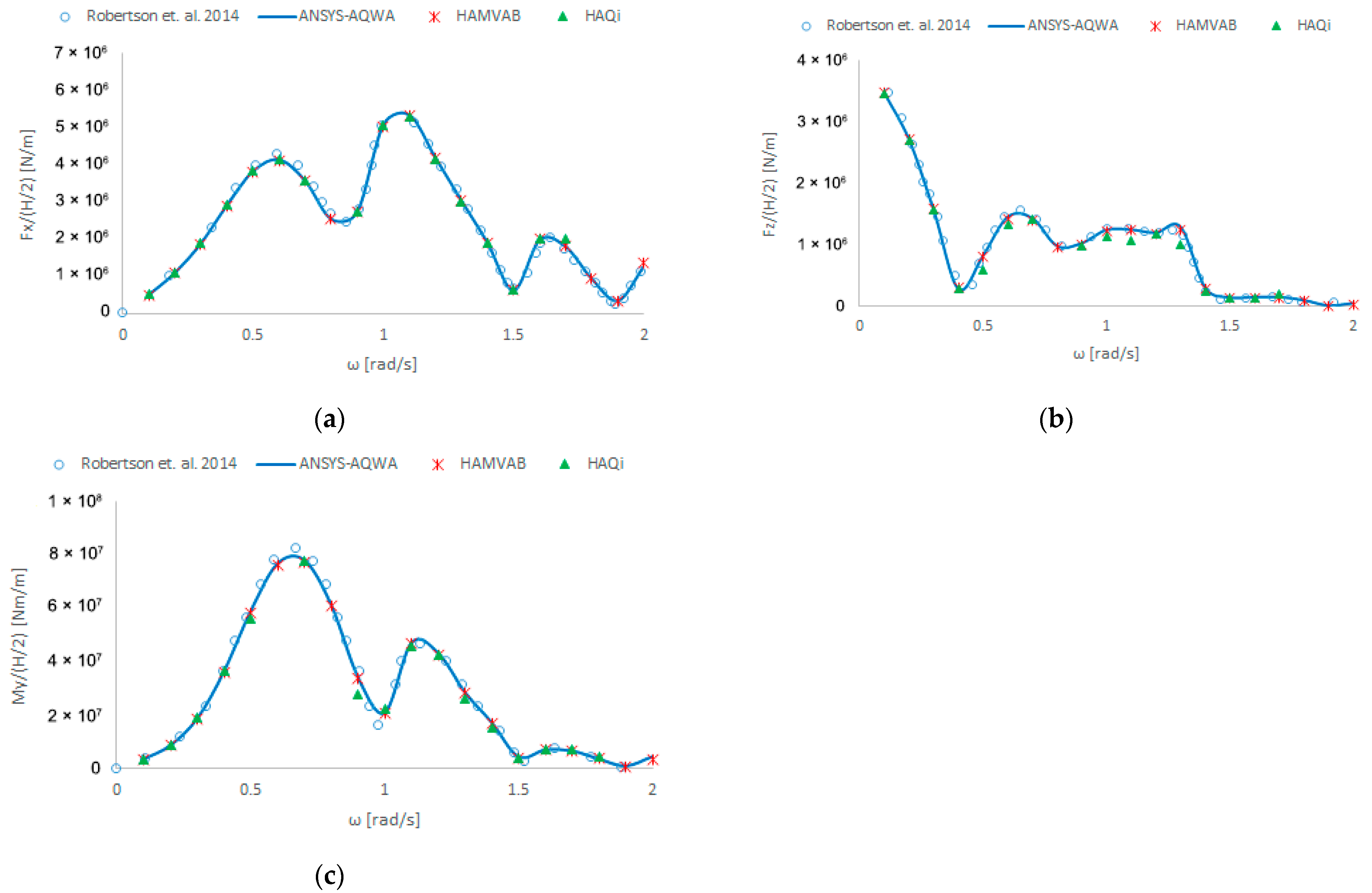
4.1.1. Exciting Wave Loads: 0-Degree Wave Heading

Figure 2 shows comparisons of the wave excitation forces exerted on the WT support structure when the wave impacts the structure at an angle of 0 degrees. As can be observed, the results are identical.

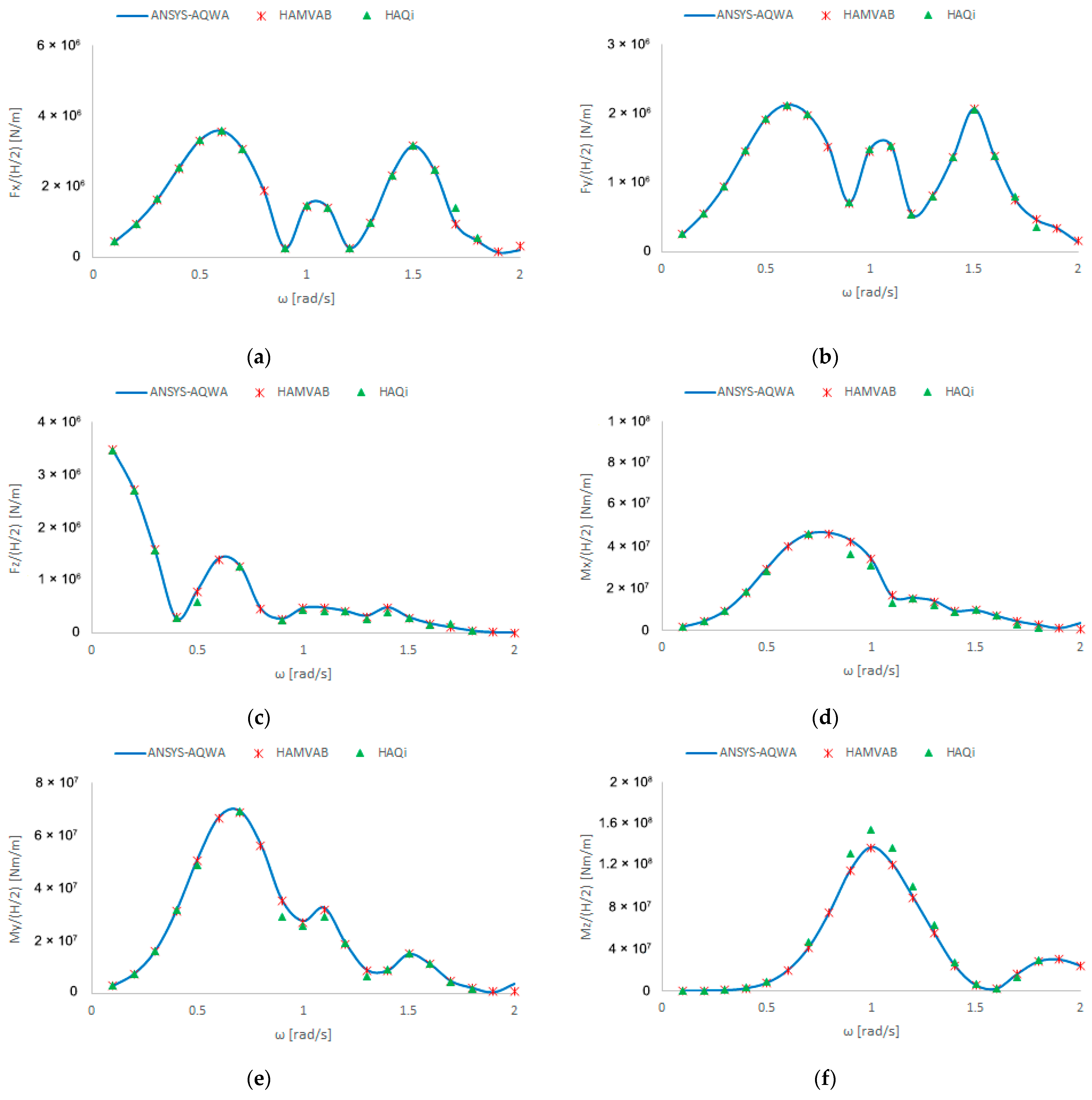
4.1.2. Exciting Wave Loads: 30-Degree Wave Heading
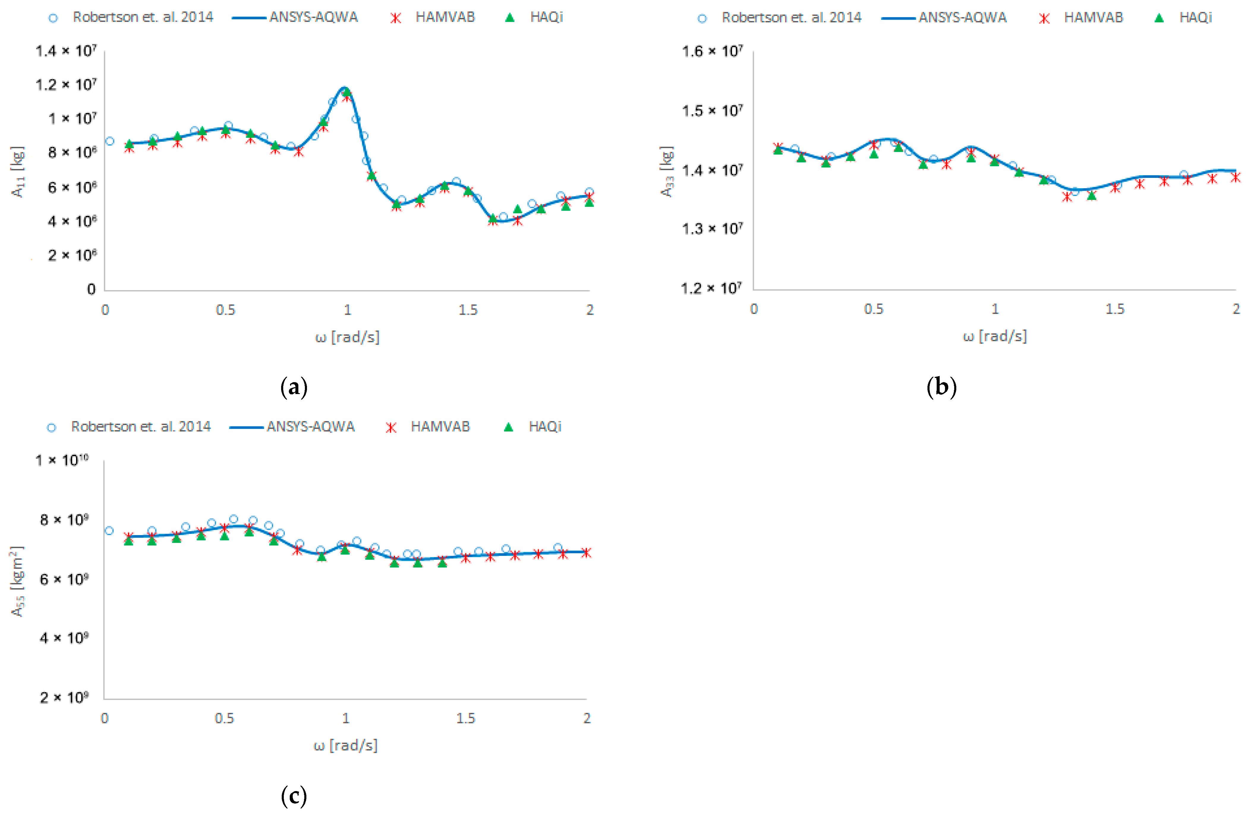
Because the body forms an equilateral triangle, due to symmetrical reasons, for every 60 degrees of a wave incidence, the forces are equal, and an angle of 30 degrees, i.e., an unsymmetrical loading, was chosen to check the loadings and interactions between the bodies of the structure.
Figure 3 shows comparisons of the wave excitation forces exerted on the WT support structure when the wave approaches the structure at an angle of 30 degrees. In this case, comparisons are made between the HAMVAB, HAQi, and ANSYS-AQWA codes. The results compare excellently with each other.

4.1.3. Added Masses

Figure 4 shows comparisons of the added masses of the WT supporting the semi-submersible structure. Excellent agreement among the results can also be reported in this case.

4.1.4. Hydrodynamic Damping

Figure 5 shows comparisons of the hydrodynamic damping of the WT support structure. Also, for the hydrodynamic damping calculations, the results showed excellent agreement.

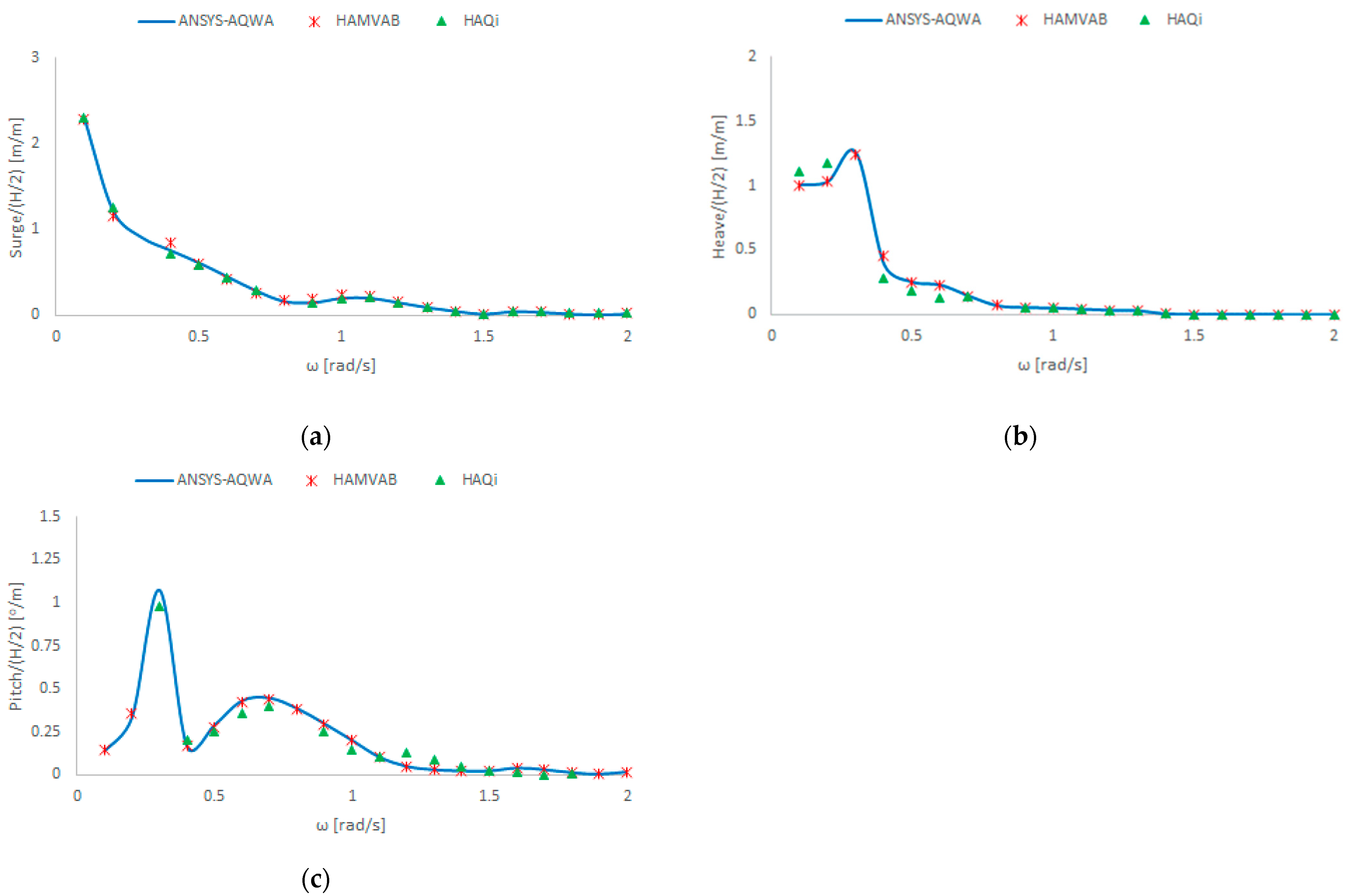
4.1.5. Response Amplitude Operators of Motion: 0-Degree Wave Heading

Figure 6 shows comparisons of the motion’s response amplitude operators (RAOs) of the WT supporting structure for a 0-degree wave heading. In this case, comparisons are made between the computer codes HAMVAB, HAQi, and ANSYS-AQWA. The results show good agreement.

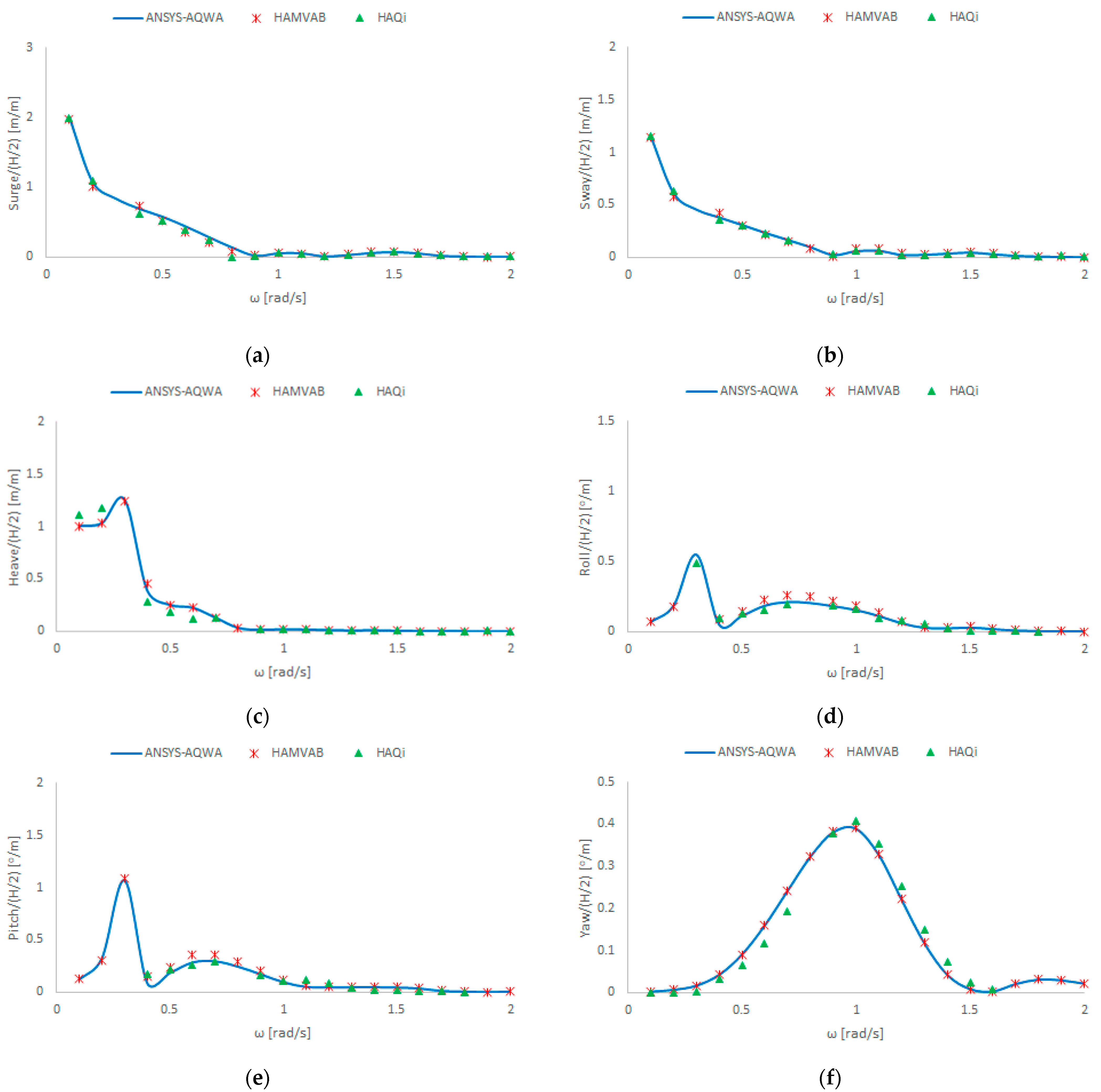
4.1.6. Response Amplitude Operators of Motion: 30-Degree Wave Heading

Figure 7 shows comparisons of the motion’s response amplitude operators (RAOs) of the WT support structure for a 30-degree wave heading. In this case, comparisons are made among the programs HAMVAB, HAQi, and ANSYS-AQWA. The results show acceptable agreement among them.

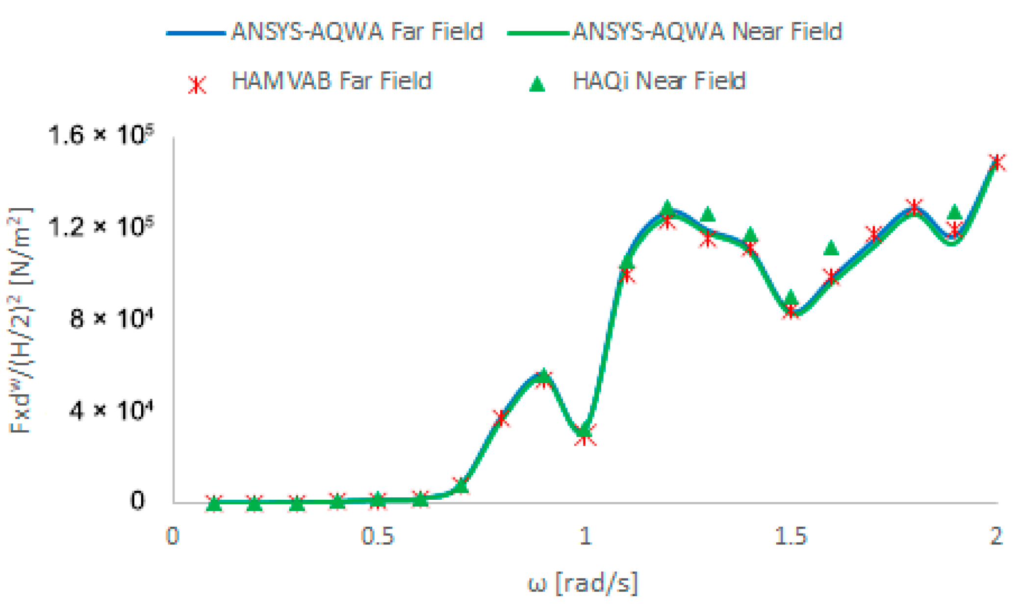
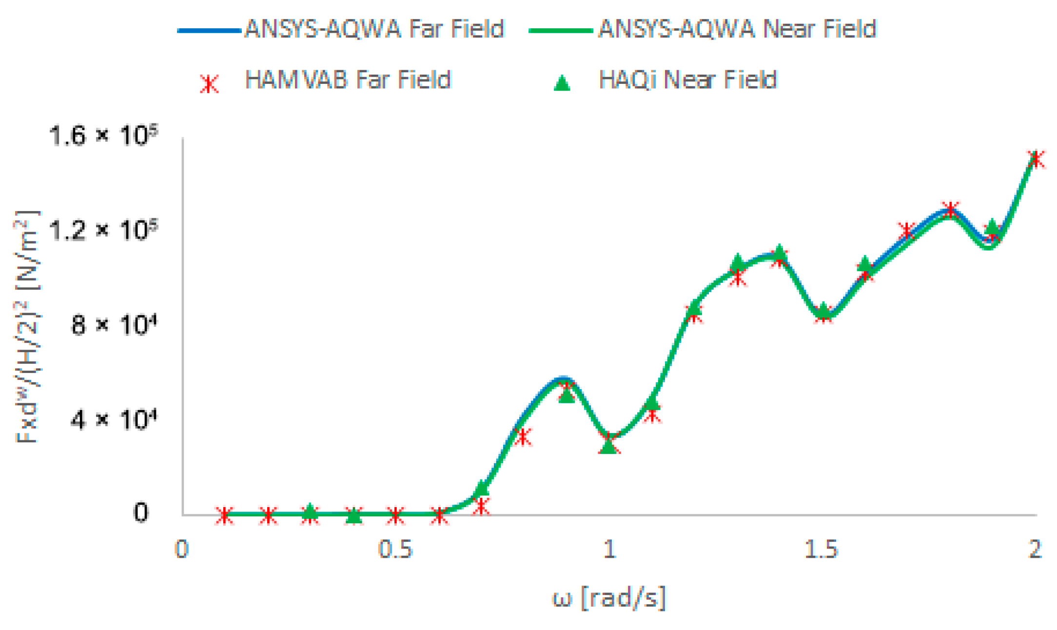
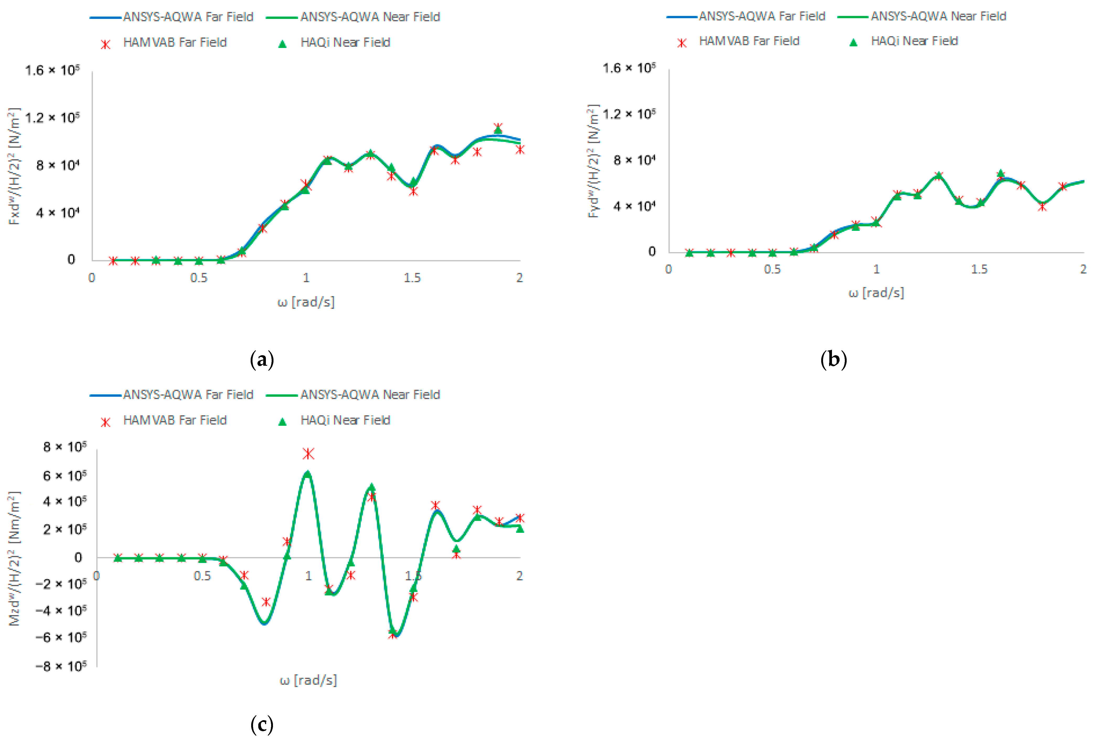
4.1.7. Mean Second-Order Wave-Drift Forces and Moments: 0- and 30-Degree Wave Headings

In order to verify the mesh used in the boundary element methods (ΒΕΜs), comparisons of the mean second-order wave-drift forces were made using both the far-field method and the near-field methods in the case where the structure was considered fixed. First-order wave fields were employed to control the quality of the mesh by comparing the obtained results. Two different techniques (near- and far-field) for the evaluation of the mean drift forces were used, along with two different methodologies (one numerical and one analytical) for the quality of the mesh.
1st: In this particular case, as shown in Figure 8, the results of the two methods are identical (i.e., ANSYS-AQWA: far-field/near-field, HAQi: near-field, numerical evaluation of the first-order potential).
2nd: These results are also compared with the HAMVAB code, which applies the momentum conservation principle for the mean second-order force evaluation, and uses semi-analytical solutions rather than discretization; so it serves as a second criterion to verify if the discretization used in the BEM codes is accurate.
The two methods were compared based on the corresponding results obtained with the ANSYS-AQWA (5663 elements) software [53]. As can be seen, the two methods provide identical results, so the grid is reliable for the calculations. Then, these results were compared with the ones obtained from HAQi (3636 elements), which makes use of the direct integration method (near-field method) for the mean-drift force evaluation. Finally, to confirm all of the above, the results were compared with HAMVAB, which calculates the mean second-order wave-drift forces using the far-field method and analytical representation of the velocity potential around the multi-body configuration. As can be observed, the results from all programs are identical (Figure 8 and Figure 9).
From the presentation of the relevant results (Figure 8), it can be seen that the comparison of the results produced by the two methods is generally good, despite the fact that they were obtained by using different numerical codes (ANSYS-AQWA and HAQi, for the near-field; HAMVAB and ANSYS-AQWA for the far-field) and different methods of solving the linearized body-wave interaction problem (numerical: ANSYS-AQWA, HAQi and analytical: HAMVAB). The near-field method requires the calculation of the potential and its derivatives on the wetted surface of the body, while the far-field avoids the evaluation of these quantities on the body and uses quantities at a distance from it, where the incident and wave-like components of the scattered potential must be taken into account. The small differences appearing in the results could be attributed to these factors. Furthermore, the different methodologies used to solve the linearized body-wave interaction problem (numerical, panel methods for ANSYS-AQWA and HAQi, and analytical for the HAMVAB case) could also justify the small discrepancies. Of course, the advantage of the direct integration method is that the mean drift loads are calculated in all six degrees of freedom, while with the far-field method only accounts for three of them (horizontal forces and yaw moments).
Figure 10 shows comparisons of the mean second-order wave-drift forces of the WT support structure for the 30-degree wave incidence. In this case, comparisons are made between the programs HAMVAB (which makes use of the far-field method with an analytical representation of the velocity potential), HAQi (which makes use of the near-field method), and ANSYS-AQWA (which calculates the mean second-order wave-drift forces with the far-field and near-field methods). As evident from the obtained results, a very good agreement between them can be reported.

4.2. Numerical Results for the Case of Coexisting Wave and Current Fields

The current velocities used in this study are equal to U = ±0.1, ±0.2, ±0.3 m/s. These current velocities refer to the Mediterranean Basin [54,55].

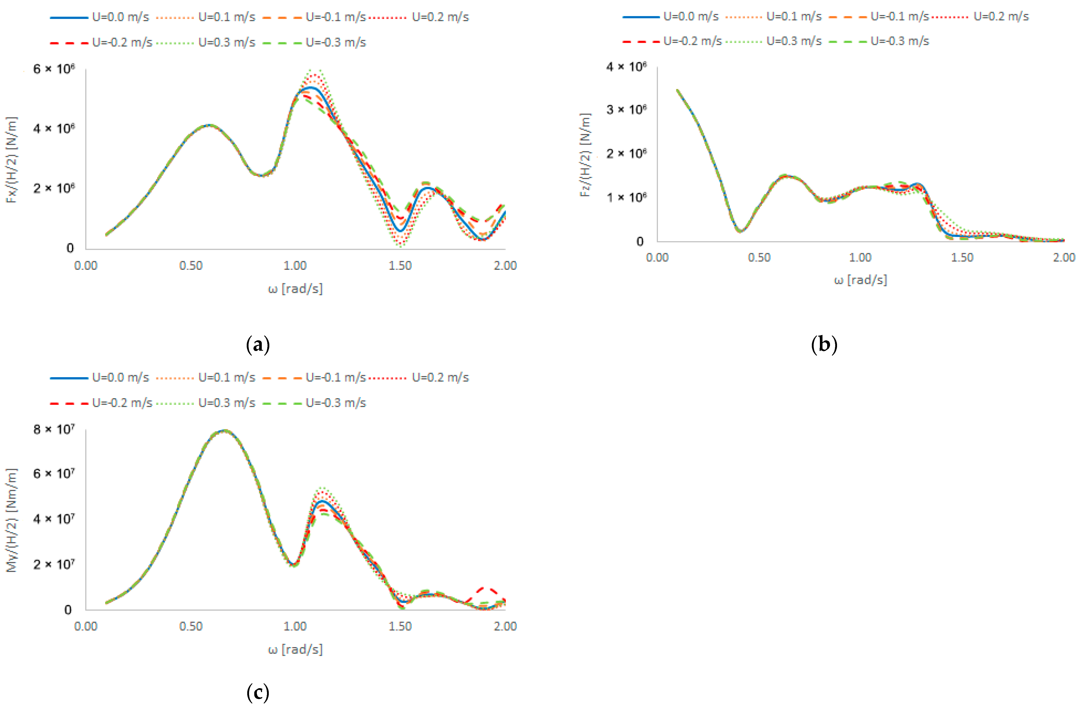
4.2.1. Exciting Wave Loads: 0-Degree Wave and Current Headings

When the wave and current are incident on the structure at the same angle (0ο), we observe that the exciting wave forces on the structure in the horizontal and vertical directions are practically not affected by the presence of the current for ω < 1 rad/s. For values of ω greater than 1 rad/s, it is evident that the forces are influenced by the presence of the sea current. The pitching exciting moments exhibit the same behavior (Figure 11).

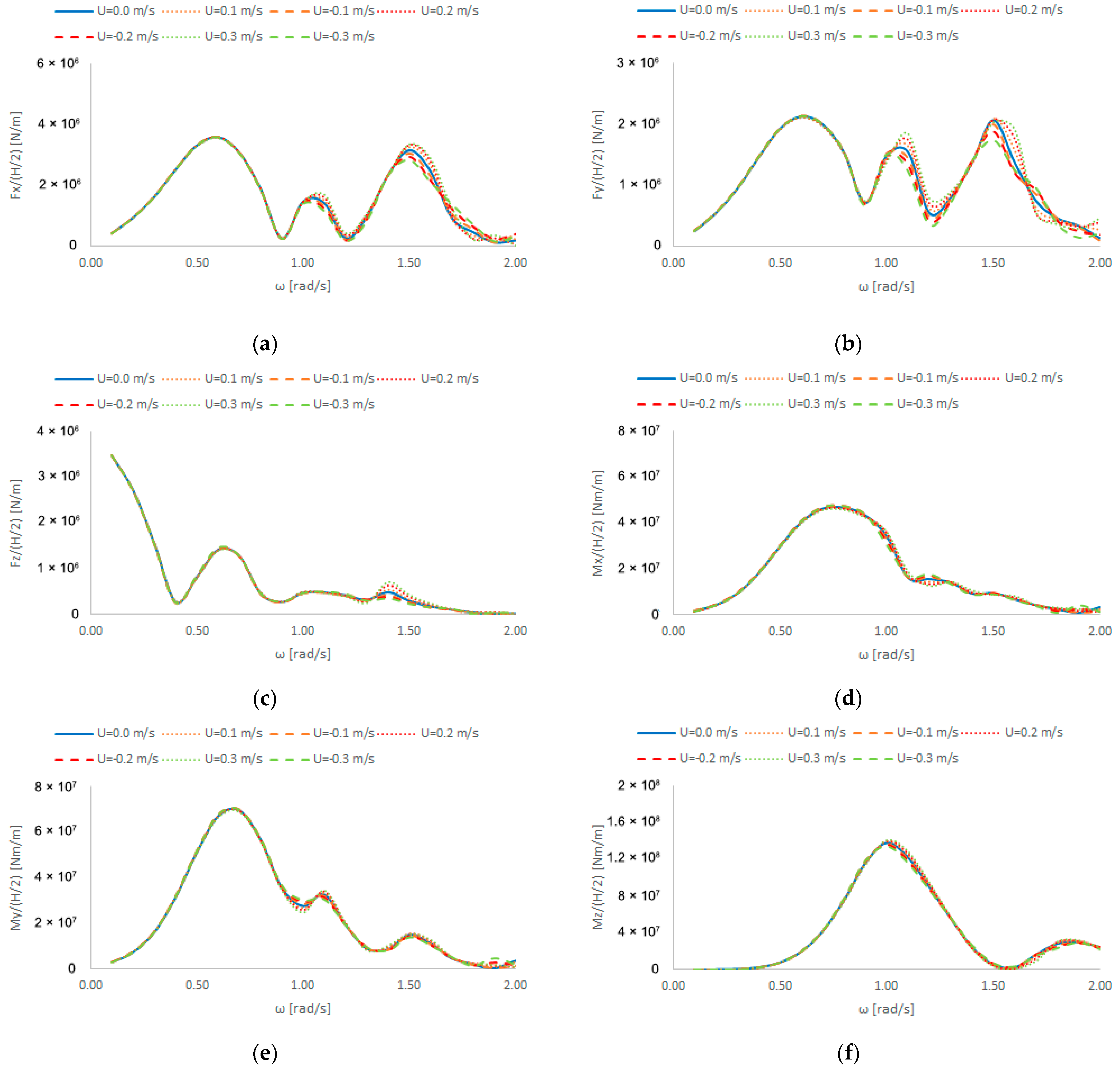
4.2.2. Exciting Wave Loads: 30-Degree Wave and 0-Degree Current Headings

When the wave incidence angle on the structure is 30 degrees and the sea current incidence angle is 0 degrees, we also observe that the exciting wave forces on the structure in the horizontal and vertical directions are not affected by the presence of the current when ω < 0.9 rad/s. However, for ω > 0.9 rad/s, the forces are affected by the presence of the sea current. The same applies to the pitch-, roll-, and yaw-exciting moments (Figure 12).

4.2.3. Added Masses Wave and Current

From the numerical results depicted in Figure 13 that deal with the added masses A11, A33, and A55, it can be concluded that the effect of the sea current is relatively small compared to the case where the structure is subjected to forced oscillations in otherwise still water in the absence of the current.

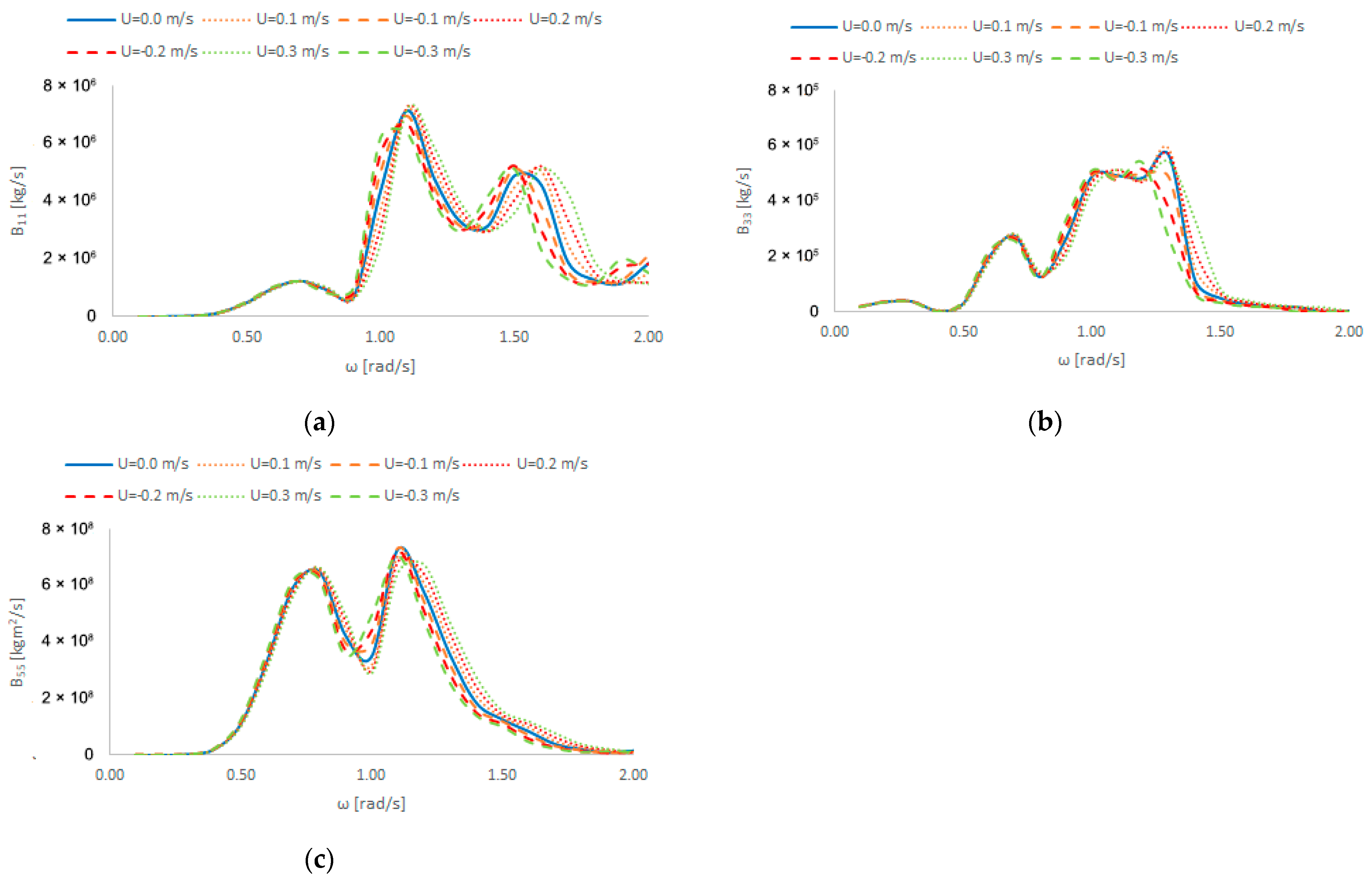
4.2.4. Hydrodynamic Damping Wave and Current

The diagrams in Figure 14 show the hydrodynamic damping coefficients B11, B33, and B55. It is evident that the sea current has a significant impact on their values compared to their zero-current counterparts.

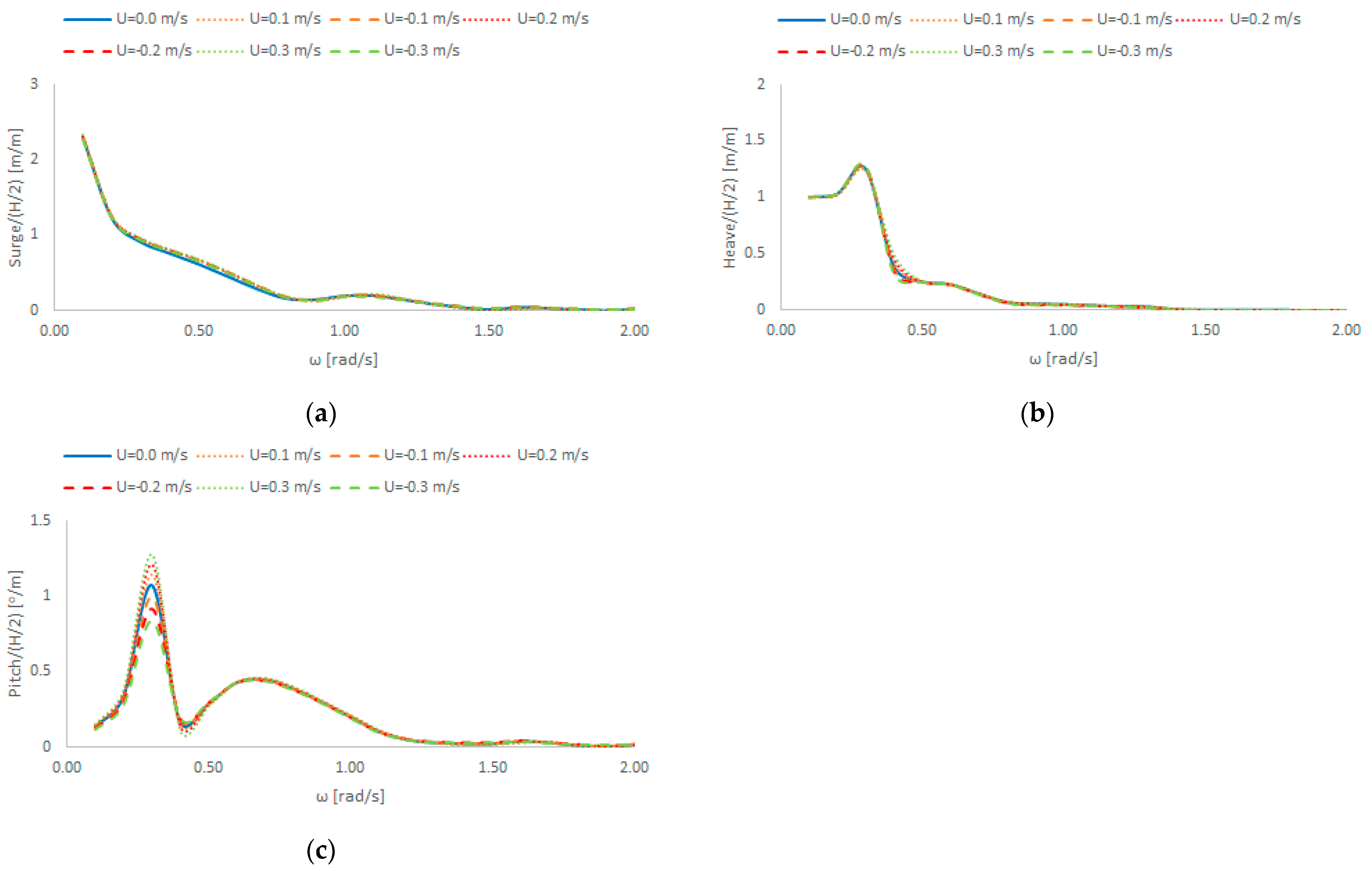
4.2.5. Motion’s Response Amplitude Operators in Wave and Current Fields: 0-Degree Wave and Current Headings

In the diagrams concerning the RAOs of motion of the floating structure, it is also observed that the effect of the sea current is relatively small on the surge, heave, and pitch motions of the floating supporting structure (Figure 15).

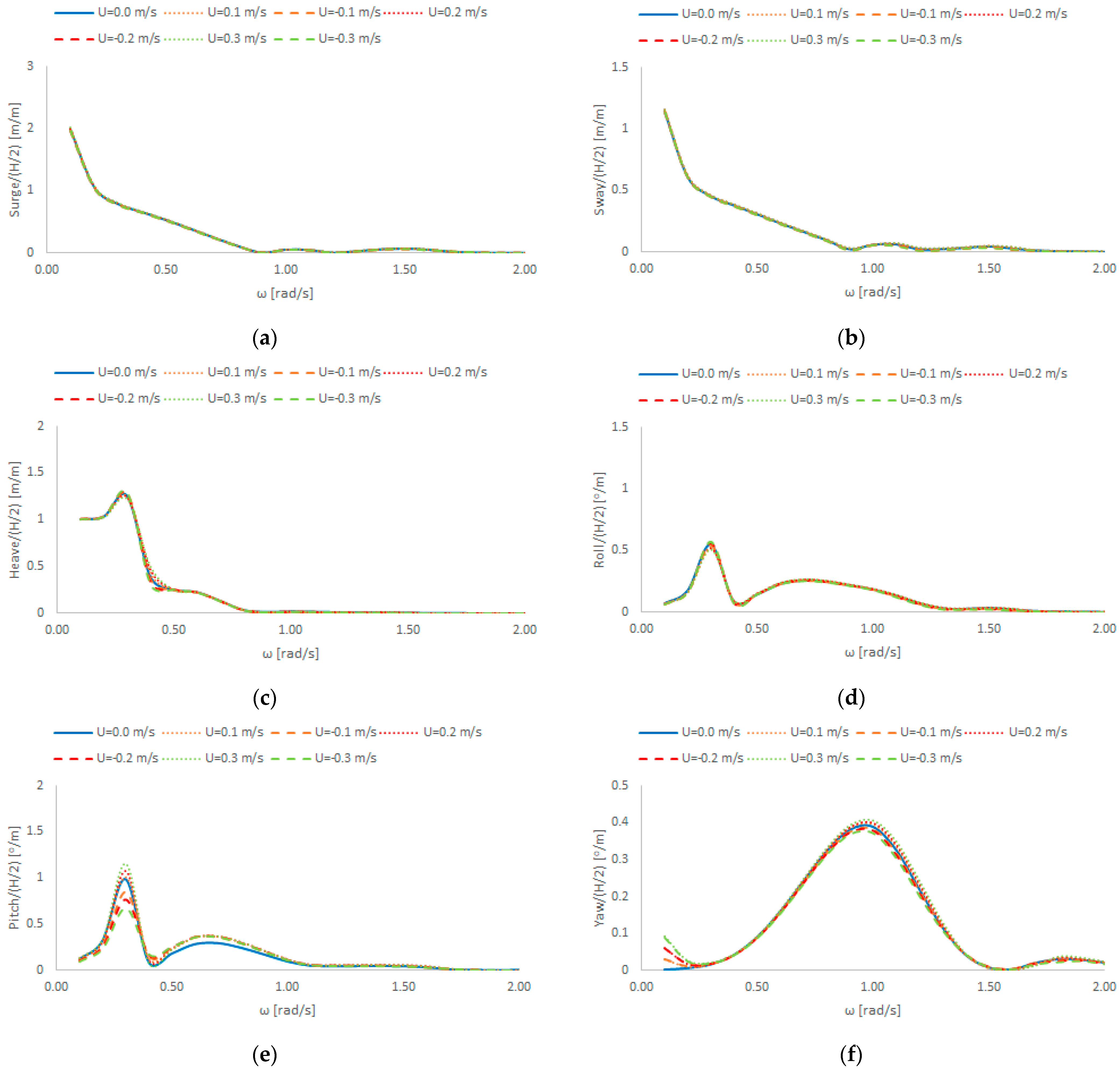
4.2.6. Motion’s Response Amplitude Operators in Wave and Current Fields: 30-Degree Wave Incidence and 0-Degree Current Headings

In the diagrams of the RAOs of the floating structure, it is also observed that the influence of the sea current is relatively small (Figure 16).

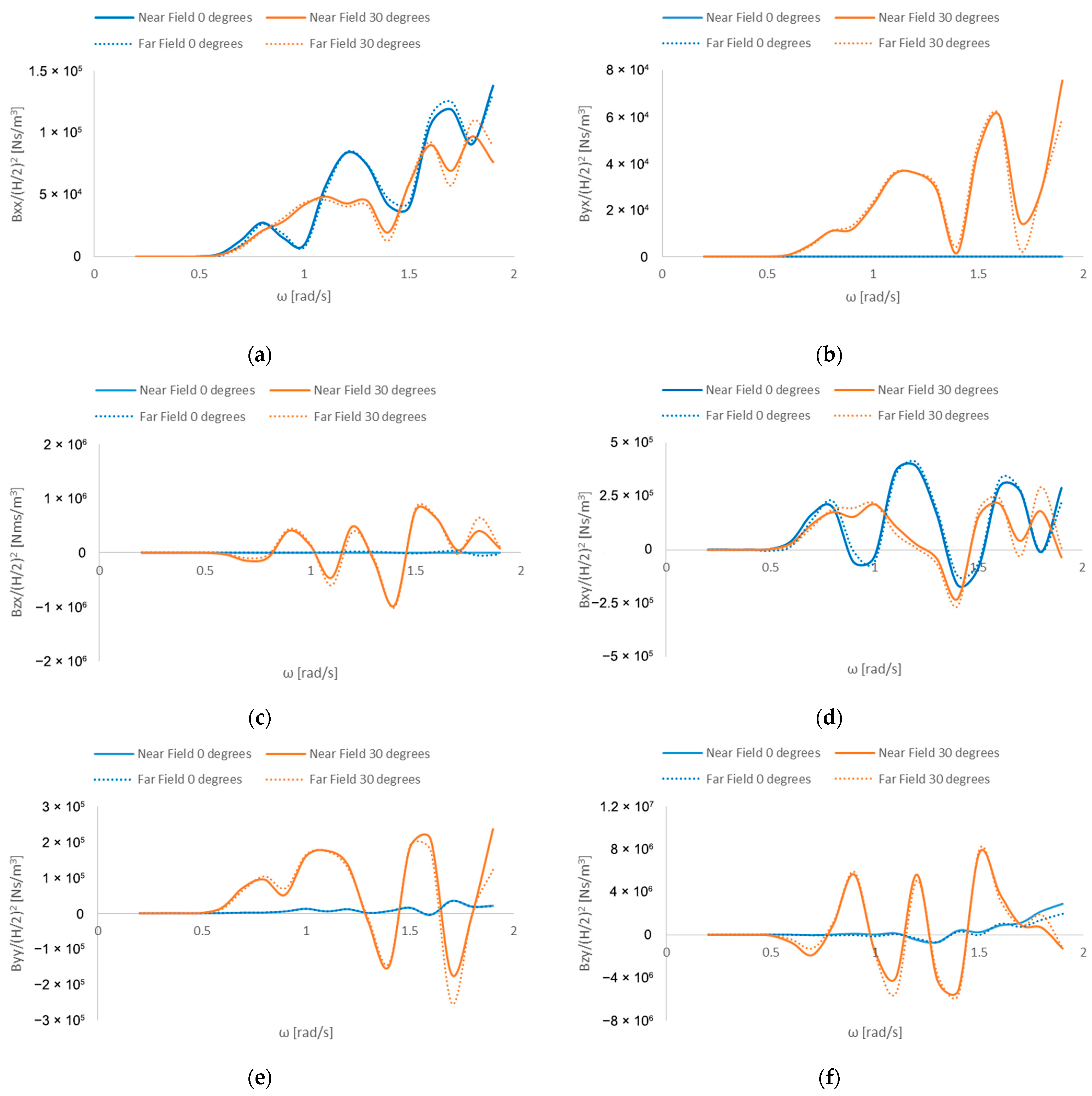
4.2.7. Wave-Drift Damping

In this section, results for the second-order wave-drift damping are presented, resulting from the mean second-order wave-drift forces calculated by HAMVAB using the far-field method and ANSYS-AQWA commercial software using the near-field method. As we can see, the results converge (Figure 17).

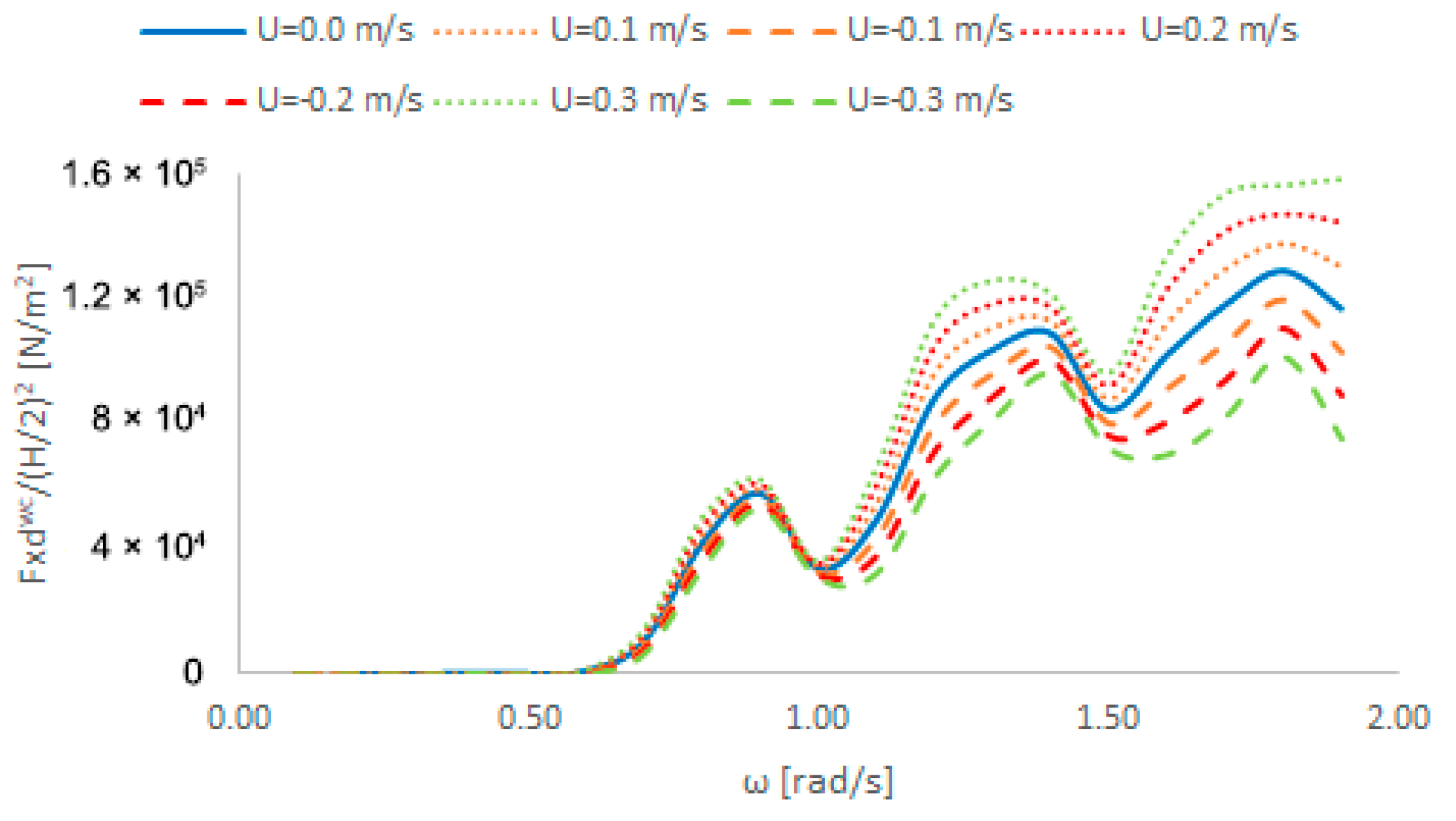
4.2.8. Mean Second-Order Drift Forces in Coexisting Wave and Current Fields: 0-Degree Wave and Current Headings

In this section, the effect of the current velocity on the mean second-order drift forces imposed on the floating OC4-DeepCwind supporting structure is analyzed. The plots of the mean second-order drift forces (wave and current interaction at an angle of 0°) show a significant effect of the sea current on their values when compared to the case where the structure is only subjected to sea waves. Figure 18 illustrates that the effect of the sea current is observed for ω > 0.5 rad/s. At high omegas, the effect increases by 12% for U = 0.1 m/s, 24% for U = 0.2 m/s, and 35% for U = 0.3 m/s. Similarly, it decreases by 12% for U = −0.1 m/s, 24% for U = −0.2 m/s, and 35% for U = −0.3 m/s.

4.2.9. Mean Second-Order Drift Forces in Coexisting Wave and Current Fields: 30-Degree Wave and 0-Degree Current Headings

When the incident wave on the structure is at a 30-degree angle and the sea current is at a 0-degree angle, the effect of the sea current occurs for ω > 0.6 rad/s. At high ω, it increases by 7% for U = 0.1 m/s, 14% for U = 0.2 m/s, and 22% for U = 0.3 m/s. Similarly, it decreases by 7% for U = −0.1 m/s, 14% for U = −0.2 m/s, and 22% for U = −0.3 m/s (see Figure 19).

5. Discussion and Conclusions

In this contribution, we presented numerical results concerning the hydrodynamic analysis of the NREL OC4 semi-submersible floating structure supporting a WT, when excited by co-existing linear waves and uniform current fields. The linearized hydrodynamic problems were solved using two methodologies (one analytical and one numerical-panel methodology) and three different computer codes for their realization. The analytical methodology is based on single-body hydrodynamic characteristics in conjunction with the concept of multiple scattering to account for the hydrodynamic interaction effects between the cylinders of the multi-body configuration, whereas the numerical approaches are based on integral equation formulations and source distributions over the body’s wetted surface. The analytical methodology applies to configurations consisting of single- or multiple hydrodynamically interacting vertical axisymmetric bodies (i.e., vertical-truncated and vertical compound cylinders in the case of the OC4 floater), whereas the numerical methods—based on integral equation formulations—can be applied to arbitrarily shaped floaters.
This publication attempts to highlight aspects of the hydrodynamic analysis of floating structures used as supporting floaters for floating WT, i.e., specifically focusing on the interaction of a floating WT in the presence of coexisting wave and current fields. The published results in the international literature are limited for this particular type of structure examined in the present contribution.
First, comparisons were made of the results obtained by the computer codes when calculating the exciting wave loads imposed on the structure in the presence of regular waves only. The comparisons of hydrodynamic characteristics were made both with analytical and BEM methods. The grid was checked using mean second-order wave-drift forces to validate it. First-order forces, added masses, hydrodynamic damping, RAOs of motion, and mean second-order wave-drift forces were all compared.
Furthermore, the hydrodynamic loadings exerted on the structure when it was exposed to the combined action of regular waves and a uniform current were presented. The first-order forces, added masses, hydrodynamic damping, RAOs of motion, mean second-order drift forces, and second-order wave-drift damping for various wave and current angles of incidence were calculated. The mean second-order drift forces in the presence of coexisting wave and current fields were determined by combining the zero-current drift force components with their corresponding first-order corrections. This approach allowed for the direct evaluation of the latter to be bypassed; instead, they were expressed in terms of their relationship to the wave-drift damping components, which were calculated utilizing a ‘heuristic’ approach. The latter can be accepted as a reliable methodology for the wave drift damping (WDD) evaluation in the particular case of the examined OC4 DeepCwind floater, as it has been supported by systematic comparisons of its numerical outcomes with pertinent experimental data from previous investigations [41]. It provides very accurate results for WDD in surge and sway modes of motion, particularly in cases of vertical cylinders and deep-drafted wall-sided floaters like the OC4 floater.
In conclusion, the strong effect of the sea current on the evaluation of the mean second-order drift forces was demonstrated, underscoring its significance in calculating the total hydrodynamic loading imposed on the structure. Therefore, it is estimated that they should be properly taken into account when designing a floating WT supporting structure.

Author Contributions

Conceptualization, T.P.M. and S.A.M.; methodology, T.P.M. and S.A.M.; software, T.P.M. and S.A.M.; validation, T.P.M. and S.A.M.; formal analysis, T.P.M. and S.A.M.; investigation, T.P.M. and S.A.M.; writing—original draft preparation, T.P.M. and S.A.M.; writing—review and editing, T.P.M. and S.A.M.; supervision, T.P.M. and S.A.M. All authors have read and agreed to the published version of the manuscript.

Funding

This research received no external funding

Institutional Review Board Statement

Not applicable.

Informed Consent Statement

Not applicable.

Data Availability Statement

Data is contained within the article.

Conflicts of Interest

The authors declare no conflicts of interest.

References

  1. Barooni, M.; Ashuri, T.; Sogut, D.V.; Stephen Wood, S.; Taleghani, S.G. Floating Offshore Wind Turbines: Current Status and Future Prospects. Energies 2023, 16, 2. [Google Scholar] [CrossRef]
  2. Jonkman, J. Definition of the Floating System for Phase IV of OC3; Technical Report; NREL/TP-500-47535; National Renewable Energy Lab (NREL): Golden, CO, USA, 2010.
  3. Shin, H. Model test of the OC3-Hywind floating offshore wind turbine. In Proceedings of the 21st International Offshore and Polar Engineering Conference (ISOPE2011), Maui, HI, USA, 19–24 June 2011. [Google Scholar]
  4. Browning, J.; Jonkman, J.; Robertson, A.; Goupee, A. Calibration and validation of a spar-type floating offshore wind turbine model using the FAST dynamic simulation tool. J. Phys. Conf. Ser. 2014, 555, 012015. [Google Scholar] [CrossRef]
  5. Robertson, A.N.; Jonkman, J.M.; Goupee, A.J.; Coulling, A.J.; Prowell, I.; Browning, J.; Masciola, M.D.; Molta, P. Summary of conclusions and recommendations drawn from the DeepCwind scaled floating offshore wind system test campaign. Int. Conf. Offshore Mech. Arct. Eng. Am. Soc. Mech. Eng. 2013, 55423, V008T09A053. [Google Scholar]
  6. Robertson, A.; Jonkman, J.; Masciola, M.; Song, H.; Goupee, A.; Coulling, A.; Luan, C. Definition of the Semisubmersible Floating System for Phase II of OC4; Technical Report; NREL/TP-5000-60601; National Renewable Energy Lab (NREL): Golden, CO, USA, 2014. Available online: https://www.nrel.gov/docs/fy14osti/60601.pdf (accessed on 1 July 2024).
  7. Benitz, M.A.; Schmidt, D.P.; Lackner, M.A.; Stewart, G.M.; Jonkman, J.; Robertson, A. Validation of hydrodynamic load models using CFD for the OC4-DeepCwind semisubmersible. In International Conference on Offshore Mechanics and Arctic Engineering; American Society of Mechanical Engineers: New York, NY, USA, 2015; Volume 56574, p. V009T09A037. [Google Scholar]
  8. Robertson, A.N.; Jonkman, J.M. Loads analysis of several offshore floating wind turbine concepts. In Proceedings of the 21st International Offshore and Polar Engineering Conference (ISOPE2011), Maui, HI, USA, 19–24 June 2011. [Google Scholar]
  9. Goupee, A.J.; Koo, B.; Lambrakos, K.; Kimball, R. Model tests for three floating wind turbine concepts. In Proceedings of the Offshore Technology Conference, Houston, TX, USA, 30 April–3 May 2012. [Google Scholar]
  10. Jaksic, V.; O’Shea, R.; Cahill, P.; Murphy, J.; Mandic, D.; Pakrashi, V. Dynamic response signatures of a scaled model platform for floating wind turbines in an ocean wave basin. Philos. Trans. R. Soc. A Math. Phys. Eng. Sci. 2015, 373, 20140078. [Google Scholar] [CrossRef]
  11. Jonkman, J.M. Dynamics Modeling and Loads Analysis of an Offshore Floating Wind Turbine; Technical Report; National Renewable Energy Lab (NREL): Golden, CO, USA, 2007.
  12. Oglivie, T.F. Second-order hydrodynamic effects on ocean platforms. In Proceedings of the International Workshop on Ship and Platform Motions, Berkeley, CA, USA, 26–28 October 1983; Yeung, R.W., Ed.; University of California: Berkeley, CA, USA, 1983; pp. 205–265. [Google Scholar]
  13. Newman, J. The second-order wave force on a vertical cylinder. J. Fluid Mech. 1996, 320, 417–443. [Google Scholar] [CrossRef]
  14. Roald, L.; Jonkman, J.; Robertson, A.; Chokani, N. The effect of second-order hydrodynamics on floating offshore wind turbines. Energy Procedia 2013, 35, 253–264. [Google Scholar] [CrossRef]
  15. Coulling, A.J.; Goupee, A.J.; Robertson, A.N.; Jonkman, J.M. Importance of second-order difference-frequency wave-diffraction forces in the validation of a fast semi-submersible floating wind turbine model. In International Conference on Offshore Mechanics and Arctic Engineering; American Society of Mechanical Engineers: New York, NY, USA, 2013; Volume 55423, p. V008T09A019. [Google Scholar]
  16. Zhang, L.; Shi, W.; Karimirad, M.; Michailides, C.; Jiang, Z. Second-order hydrodynamic effects on the response of three semisubmersible floating offshore wind turbines. Ocean Eng. 2020, 207, 107371. [Google Scholar] [CrossRef]
  17. Gueydon, S.; Jonkman, J. Update on the Comparison of Second-Order Loads on a Tension Leg Platform for Wind Turbines; Technical Report; National Renewable Energy Lab (NREL): Golden, CO, USA, 2016.
  18. Li, Y.; Tang, Y.; Zhu, Q.; Qu, X.; Wang, B.; Zhang, R. Effects of second-order wave forces and aerodynamic forces on dynamic responses of a TLP-type floating offshore wind turbine considering the set-down motion. J. Renew. Sustain. Energy 2017, 9, 063302. [Google Scholar] [CrossRef]
  19. Newman, J.N. Second-order, slowly varying forces on vessels in irregular waves. In Proceedings of the International Symposium on the Dynamics of Marine Vehicles and Structures in Waves, London, UK, 1–5 April 1974. [Google Scholar]
  20. Pinkster, J.A. Low-frequency phenomena associated with vessels moored at sea. Soc. Pet. Eng. J. 1975, 15, 487–494. [Google Scholar] [CrossRef]
  21. Mavrakos, S.A. Mean drift loads on multiple vertical axisymmetric bodies in regular waves. In Proceedings of the 5th International offshore and Polar Engineering Conference, The Hague, The Netherlands, 11–16 June 1995; International Society of Offshore and Polar Engineers: Cupertino, CA, USA, 1995; Volume III, pp. 547–555. [Google Scholar]
  22. Zhao, R.; Faltinsen, O.M. Interaction between current, waves, and marine structures. In Proceedings of the 5th International Conference on Numerical Ship Hydrodynamics, Hiroshima, Japan, 24–28 September 1989; National Academy Press: Washington, DC, 1990; pp. 87–99. [Google Scholar]
  23. Faltinsen, O.M. Wave and current-induced motions of floating production systems. Appl. Ocean Res 1994, 15, 351–370. [Google Scholar] [CrossRef]
  24. Molin, B. Second-order hydrodynamics applied to moored structure—A state-of-the-art survey. Ship Technol. Res. 1994, 41, 59–84. [Google Scholar]
  25. Mazarakos, T.P. Second-order wave loading and wave drift damping on floating marine structures. Ph.D. Thesis, School of Naval Architecture and Marine Engineering, Division of Marine Structures, Laboratory of Floating Structures and Mooring Systems, National Technical University of Athens, Athens, Greece, 2010; pp. 1–272. [Google Scholar]
  26. Zheng, Z.; Chen, J.; Liang, H.; Zhao, Y.; Shao, Y. Hydrodynamic Responses of a 6 MW Spar-Type Floating Offshore Wind Turbine in Regular Waves and Uniform Current. Fluids 2020, 5, 187. [Google Scholar] [CrossRef]
  27. Magkouris, A.; Belibassakis, K. A Novel BEM–FEM Scheme for the Interaction of Water Waves with Multiple Vertical Cylinders in the Presence of Currents. Fluids 2022, 7, 378. [Google Scholar] [CrossRef]
  28. Emmerhoff, O.J.; Sclavounos, P.D. The slow drift motion of arrays of vertical cylinders. J. Fluid Mech. 1992, 242, 31–50. [Google Scholar] [CrossRef]
  29. Nossen, J.; Grue, J.; Palm, E. Wave forces on three-dimensional floating bodies with small forward speed. J. Fluid Mech. 1991, 227, 135–160. [Google Scholar] [CrossRef]
  30. Grue, J.; Palm, E. The mean drift force and yaw moment on marine structures in waves and current. J. Fluid Mech. 1993, 250, 121–142. [Google Scholar] [CrossRef]
  31. Grue, J.; Biberg, D. Wave forces on marine structures with small speed in water of restricted depth. Appl. Ocean Res. 1993, 15, 121–135. [Google Scholar] [CrossRef]
  32. Chen, X.B.; Malenica, S. Uniformly valid solution of the wave-current-body interaction problem. In Proceedings of the 11th International Workshop on Water Waves and Floating Bodies, Hamburg, Germany, 17–20 March 1996; pp. 149–152. Available online: www.iwwwfb.org (accessed on 1 July 2024).
  33. Maruo, H. The drift of a body floating in waves. J. Ship Res. 1960, 4, 1–10. [Google Scholar]
  34. Newman, J.N. The drift force and moment on ships in waves. J. Ship Res. 1967, 11, 51–60. [Google Scholar] [CrossRef]
  35. Pinkster, J.A.; van Oortmerssen, G. Computation of the first- and second-order wave forces on oscillating bodies in regular waves. In Proceedings of the 2nd International Conference on Numerical Ship Hydrodynamics, Berkley, CA, USA; 1977; pp. 136–156. [Google Scholar]
  36. Clark, P.J.; Malenica, S.; Molin, B. An heuristic approach to wave drift damping. Appl. Ocean Res. 1993, 15, 53–55. [Google Scholar] [CrossRef]
  37. Aranha, J.A.P. A formula for the wave damping in the drift of a floating body. J. Fluid Mech. 1994, 275, 147–155. [Google Scholar] [CrossRef]
  38. Malenica, S.; Clark, P.J.; Molin, B. Wave and current forces on a vertical cylinder free to surge and sway. Appl. Ocean Res. 1995, 17, 79–90. [Google Scholar] [CrossRef]
  39. Hermans, A.J.; Sierevogel, L.M. A discussion on the second-order wave forces and wave drift damping. Appl. Ocean Res. 1996, 18, 257–263. [Google Scholar] [CrossRef]
  40. Martin, A.J.; Easson, W.J. Nonlinear internal wave kinematics. In Proceedings of the 7th International Offshore and Polar Engineering Conference (ISOPE 1997), Honolulu, HI, USA, 25–30 May 1997; Volume III, pp. 122–129. [Google Scholar]
  41. Trassoudaine, D.; Naciri, M. A comparison of a heuristic wave-drift damping formula with experimental results. Appl. Ocean Res. 1999, 21, 93–97. [Google Scholar] [CrossRef]
  42. Newman, J.N. Wave-drift damping of floating bodies. J. Fluid Mech. 1993, 249, 241–259. [Google Scholar] [CrossRef]
  43. Mavrakos, S.A.; Chatjigeorgiou, I.K.; Mazarakos, T.P.; Thanos, I. Second-order wave drift damping in hydrodynamically interacting large bodies. In Proceedings of the 17th International Offshore and Polar Engineering Conference, Lisbon, Portugal, 1–6 July 2007; International Society of Offshore and Polar Engineers: Cupertino, CA, USA, 2007; pp. 2142–2149. [Google Scholar]
  44. Mazarakos, T.P.; Mavrakos, S.A. Wave-current interaction on a vertical truncated cylinder floating in finite-depth waters. Proc. Inst. Mech. Eng.Part M J. Eng. Marit. Environ. 2013, 227, 243–255. [Google Scholar] [CrossRef]
  45. Chen, L.; Basu, B. Wave-current interaction effects on structural responses of floating offshore wind turbines. Wind Energy 2019, 22, 327–339. [Google Scholar] [CrossRef]
  46. Zhang, X.; Simons, R.; Zheng, J.; Zhang, C. A review of the state of research on wave-current interaction in nearshore areas. Ocean Eng. 2022, 243, 110202. [Google Scholar] [CrossRef]
  47. Elobeid, M.; Pillai, A.C.; Tao, L.; Ingram, D.; Hanssen, J.E.; Mayorga, P. Implications of wave-current interaction on the dynamic responses of a floating offshore wind turbine. Ocean Eng. 2024, 292, 116571. [Google Scholar] [CrossRef]
  48. Mavrakos, S.A.; Koumoutsakos, P. Hydrodynamic interaction among vertical axisymmetric bodies restrained in waves. Appl. Ocean Res. 1987, 9, 128–140. [Google Scholar] [CrossRef]
  49. Mavrakos, S.A. Hydrodynamic coefficients for groups of interacting vertical axisymmetric bodies. Ocean Eng. 1991, 18, 485–515. [Google Scholar] [CrossRef]
  50. Kokkinowrachos, K.; Mavrakos, S.A.; Asorakos, S. Behavior of vertical bodies of revolution in waves. Ocean Eng. 1986, 13, 505–538. [Google Scholar] [CrossRef]
  51. Bardis, L.; Mavrakos, S.A. Hydrodynamic analysis of large offshore units. In Proceedings of the 3rd IMAEM International Congress on Marine Technology, Athens, Greece, 28 May–1 June 1984; pp. 505–513. [Google Scholar]
  52. Wehausen, J.V.; Laitone, E.V. Surface waves. In Encyclopedia of Physics; Springer: Berlin/Heidelberg, Germany, 1960; Volume 9. [Google Scholar]
  53. ANSYS. Aqwa User Manual; Release 2022 R1; ANSYS, Inc.: Canonsburg, PA, USA, 2022. [Google Scholar]
  54. El-Geziry, T.M.; Bryden, I.G. The circulation pattern in the Mediterranean Sea: Issues for modeller consideration. J. Oper. Oceanogr. 2010, 3, 39–46. [Google Scholar] [CrossRef]
  55. Martínez, J.; García-Ladona, E.; Ballabrera-Poy, J.; Isern-Fontanet, J.; González-Motos, S.; Allegue, J.M.; González-Haro, C. Atlas of surface currents in the Mediterranean and Canary-Iberian-Biscay waters. J. Oper. Oceanogr. 2024, 17, 40–62. [Google Scholar] [CrossRef]
Figure 1. Photorealistic representation of the floating structure.
Jmse 12 01509 g001
Figure 2. (a) Fx horizontal wave exciting force; (b) Fz vertical wave exciting force; (c) My wave exciting moment. Robertson et. al. 2014 [6].
Jmse 12 01509 g002
Figure 3. (a) Fx horizontal wave exciting force; (b) Fy horizontal wave exciting force; (c) Fz vertical wave exciting force; (d) Mx wave exciting moment; (e) My wave exciting moment; (f) Mz wave exciting moment.
Jmse 12 01509 g003
Figure 4. (a) A11 added mass; (b) A33 added mass; (c) A55 added mass. Robertson et. al. 2014 [6].
Jmse 12 01509 g004
Figure 5. (a) B11 hydrodynamic damping; (b) B33 hydrodynamic damping; (c) B55 hydrodynamic damping. Robertson et. al. 2014 [6].
Jmse 12 01509 g005
Figure 6. (a) Surge RAO with wave; (b) heave RAO with wave; (c) pitch RAO with wave.
Jmse 12 01509 g006
Figure 7. (a) Surge RAO with wave; (b) sway RAO with wave; (c) heave RAO with wave; (d) roll RAO with wave; (e) pitch RAO with wave; (f) yaw RAO with wave.
Jmse 12 01509 g007
Figure 8. Fxdw mean second-order wave-drift forces for the fixed structure with a 0-degree wave heading.
Jmse 12 01509 g008
Figure 9. Fxdw mean second-order wave-drift forces for the free-floating body with a 0-degree wave heading.
Jmse 12 01509 g009
Figure 10. (a) Fxdw mean second-order wave-drift forces; (b) Fydw mean second-order wave-drift forces; (c) Mzdw mean second-order wave-drift forces, for a 30-degree wave heading.
Jmse 12 01509 g010
Figure 11. (a) Fx horizontal wave and current exciting force; (b) Fz vertical wave and current exciting force; (c) My wave and current exciting moment.
Jmse 12 01509 g011
Figure 12. (a) Fx horizontal wave and current exciting force; (b) Fy horizontal wave and current exciting force; (c) Fz vertical wave and current exciting force; (d) Mx wave and current exciting moment; (e) My wave and current exciting moment; (f) Mz wave and current exciting moment.
Jmse 12 01509 g012
Figure 13. (a) A11 added mass with wave and current; (b) A33 added mass with wave and current; (c) A55 added mass with wave and current.
Jmse 12 01509 g013
Figure 14. (a) B11 hydrodynamic damping with wave and current; (b) B33 hydrodynamic damping with wave and current; (c) B55 hydrodynamic damping with wave and current.
Jmse 12 01509 g014
Figure 15. (a) Surge RAO with wave and current; (b) heave RAO with wave and current; (c) pitch RAO with wave and current.
Jmse 12 01509 g015
Figure 16. (a) Surge RAO with wave and current; (b) sway RAO with wave and current; (c) heave RAO with wave and current; (d) roll RAO with wave and current; (e) pitch RAO with wave and current; (f) yaw RAO with wave and current.
Jmse 12 01509 g016
Figure 17. (a) Bxx wave-drift damping; (b) Byx wave-drift damping; (c) Bzx wave-drift damping; (d) Bxy wave-drift damping; (e) Byy wave-drift damping; (f) Bzy wave-drift damping.
Jmse 12 01509 g017
Figure 18. Fxdwc wave and current mean second-order drift forces for 0-degree wave and current headings.
Jmse 12 01509 g018
Figure 19. (a) Fxdwc wave and current mean second-order drift forces; (b) Fydwc wave and current mean second-order drift forces.
Jmse 12 01509 g019
Disclaimer/Publisher’s Note: The statements, opinions and data contained in all publications are solely those of the individual author(s) and contributor(s) and not of MDPI and/or the editor(s). MDPI and/or the editor(s) disclaim responsibility for any injury to people or property resulting from any ideas, methods, instructions or products referred to in the content.

