Article

Design of a Trajectory Tracking Controller for Marine Vessels with Asymmetric Constraints Using a New Universal Barrier Function

School of Electrical and Photoelectronic Engineering, West Anhui University, Lu’an 237012, China
*
Author to whom correspondence should be addressed.
J. Mar. Sci. Eng. 2024, 12(9), 1545; https://doi.org/10.3390/jmse12091545
Submission received: 19 July 2024 / Revised: 28 August 2024 / Accepted: 2 September 2024 / Published: 4 September 2024
(This article belongs to the Special Issue Motion Control and Path Planning of Marine Vehicles—3rd Edition)

Abstract

:
This article introduces an innovative trajectory tracking control methodology for a marine vessel with disturbances. The vessel is driven to track a predetermined trajectory while preventing the constraint violation of the position error. A universal barrier Lyapunov function (BLF) is, for the first time, established to resolve the variable constraint. It should be emphasized that the devised barrier function can handle constraint types including time-varying, time-invariant, symmetric, and asymmetric forms, and it can be employed to devise control schemes for unconstrained systems. Consequently, in comparison to the current BLF-based techniques for vessels, it can be flexible for dealing with practical control issues with or without constraints. A simplified disturbance observer performs estimations of ocean disturbances. It is proven that all the error variables can be exponentially stabilized to a small neighborhood close to the equilibrium point, while violations of the constraints on the position error never occur. The feasibility of the theoretical discoveries is shown by the outcomes of the final simulation.

1. Introduction

With the continuous development of global trade and logistics, the marine transport industry is increasingly prospering, and vessel motion control, as an important guarantee for maritime transport, has also ushered in unprecedented development opportunities. In recent years, a growing amount of research has been conducted concerning surface vessel motion control, including trajectory tracking control [1,2,3,4], dynamic positioning control [5,6,7], path-following control [8,9,10,11], automatic berthing [12], formation control [13,14,15,16], etc. Trajectory tracking, in contrast to path-following control, necessitates that the vessels arrive at an advanced pre-set trajectory within a specific time frame. In addition, trajectory tracking control is a key element of ship motion control that has been extensively researched theoretically by academics, leading to the proposal of numerous effective control strategies [17,18,19].
Sliding mode control is the approach most commonly employed for ship trajectory tracking control [20]. An adaptive sliding mode control for an autonomous vehicle was created in [21], where the fuzzy logic control was utilized to reduce the chattering in the control input. In order to overcome the challenges in autonomous vehicle control, such as ocean interference, nonlinear dynamics, and unknown dynamics, a terminal sliding control strategy was introduced in [22] to complete trajectory tracking control. A continuous proportional-integral sliding mode surface was established in [23] to improve the ship tracking system’s robustness while eliminating chatter brought on by environmental disturbances. The majority of the influence of integrated disturbances on ship motion control performance was reduced by using a disturbance observer in [24]. The impact of the remaining estimate errors was then minimized by utilizing a super-twisting sliding mode control. Backstepping control technology is most frequently included in vessel trajectory tracking control design [25,26]. For instance, the backstepping method was incorporated into sliding mode control to stabilize the error dynamics of the vessel tracking system [27]. An adaptive control approach combined with the backstepping method makes it possible for the controller that was suggested to cope with some faults in the vessels and the controller itself [28]. In [29], adaptive assistance algorithms were created to deal with the effects of input saturation, and the tracking control approach for vessels was established utilizing a combination of dynamic surface control and backstepping. In [30], a novel tracking control based on model predictive control was developed, along with an interference observer and Kalman filter, for vessels to address roll constraints and sea interferences. In [31,32,33,34], some finite/fixed-time control techniques were applied to vessel trajectory tracking control to accelerate the convergence speed of the system. Intelligent control technologies, such as neural networks and fuzzy control, are also utilized in vessel trajectory tracking control to integrate dynamic surface control, sliding mode control, model predictive control, and other techniques that enhance the system’s robustness and adaptability [35,36,37,38].
The state or output of vessels sailing in the ocean, especially in narrow channels, will inevitably be limited. As a result, vessel trajectory tracking control must fully take constraint control into account. In the recent decade or so, the barrier Lyapunov function (BLF) has been the most widely used constraint control technique [39,40]. Many barrier functions, primarily of the logarithmic [41], integral [42], and tangent types [43], have been devised by researchers through their persistent efforts. For vessel constraint control, the symmetric time-invariant logarithmic BLF was employed to prevent violations of constraints on the state variable of tracking systems [44,45]. In [46], a symmetric BLF was introduced to develop a trajectory tracking controller for marine vessels, where the prescribed position tracking constraints were solved well. An integral BLF was employed to devise an adaptive trajectory tracking controller for an underactuated vehicle for preventing the violation of the system constraints [47]. In [48], the tangent BLF was utilized to cope with the symmetric constant constraint for vessels. To prevent the ship’s state from breaking the constraints, the authors from [49] employed a time-varying tangent BLF to deal with the limitation needs that change over time. We know that symmetric constraint boundaries are symmetric about the X-axis, and asymmetric constraints are asymmetric about the X-axis. Therefore, the traditional symmetric barrier function cannot be used to deal with the asymmetric constraints of the system. Regretfully, the barrier functions mentioned previously are only applicable to managing symmetric constraint situations. Once the constraints become asymmetrical, they will be powerless. To address this difficulty, scholars have extended the symmetric logarithm BLF into a form that can effectively solve asymmetric constraint problems by introducing a piecewise function. For instance, the authors from [50] utilized extended logarithmic BLF to accommodate the asymmetric constraint situations of ships. It is worth noting that although extended logarithmic BLFs can adapt to asymmetric constraint situations, they are powerless with regard to establishing controllers for unconstrained systems.
In response to the limitations of BLFs discussed above in handling constraints, we aim to innovate a universal BLF that can adapt to various forms of constraint situations, including symmetric, asymmetric, time-varying, and non-time-varying scenarios, as well as having the ability to create controllers for unconstrained systems. In the author’s previously published article [51], a logarithmic BLF was devised to cope with symmetric constraint issues and was employed to deduce the control for systems that have unconstrained demands. Correspondingly, we will extend the barrier function in [51] into one that can accommodate asymmetric constraint situations. Moreover, the disturbance observer in [51,52] will be further improved in this article. The following is a summary of this study’s primary novel findings.
(I) A novel universal barrier function, which is different from commonly used logarithmic and tangent ones [45,48,49,50,51], is devised to accommodate symmetric, asymmetric, time-varying, and non-time-varying constraint scenarios, as well as unconstrained situations.
(II) In this work, an improved observer is devised. It does simplify the structure of the observer and does not need to perform stability analysis on the observer separately [51,52].
(III) To help with system stability analysis, an inequality about the barrier function is offered. It is demonstrated that the controlled variables can exponentially converge to a small range around the expected value based on the given inequality. We also demonstrate theoretically that the offered barrier function is applicable to systems that do not have constraints.
The rest of this article is structured as follows: Preliminaries, such as the vessel mathematical model, control objective, and introduction of the universal barrier function, are provided in Section 2. To make the state vector track the expected value, the tracking controller is developed in Section 3, and to increase the tracking system’s robustness, a simplified observer is built. A three-degree-of-freedom surface vessel model is employed in the simulation research in Section 4 to demonstrate the feasibility of the devised trajectory tracking approach. In Section 5, conclusions are outlined.

2. Preliminaries

2.1. Vessel Mathematical Model

The vessel mathematical model, which only considers surge, sway, and yaw motions, can be expressed by [53,54]
η ˙ = R ψ V M V ˙ + C V V + D V V = τ t + d
where η = χ 1 , χ 2 , ψ T denotes the position vector, V = u , v , r T represents the velocity vector. and M , C , and D are the inertia matrix, Coriolis and centripetal matrix, and damping matrix, respectively. The ocean disturbances are represented by d ( t ) . The matrix R ( ψ ) is expressed as follows:
R ψ = cos ψ sin ψ 0 sin ψ cos ψ 0 0 0 1
where R 1 = R T . Please refer to [53,54] for comprehensive information on vessel mathematical models.
To facilitate the derivation of the controller using backstepping technology, the system (1) can be changed to the following state equation by setting x 1 = η and x 2 = V , as follows:
x ˙ 1 = R ψ x 2 x ˙ 2 = M 1 τ t + d C x 2 x 2 D x 2 x 2

2.2. Control Objective

Before clarifying the control objective, we first define the following tracking error vector:
z 1 = z 11 , z 12 , z 13 T = x 1 η d z 2 = z 21 , z 22 , z 23 T = x 2 χ α
where η d and χ α are the desired position set by the user and the expected velocity designed later, respectively.
The control objective focuses on deducing a novel constraint control scheme to force the position vector x 1 to follow preset trajectories η d . Furthermore, all the closed-loop variables are exponentially stable, and the constraint situations on the position vectors k l , i < z 1 i < k u , i , i = 1 , 2 , 3 are never broken, where k u , i and k l , i are positive functions of time and are differentiable with respect to time.
Assumption 1. 
There exist constants U ¯ > 0 and U ¯ d o t > 0 , such that | d | U ¯ and | d ˙ | U ¯ d o t hold.
To achieve the control objective, namely that the position error will be constrained to the set Ω z 1 i = z 1 i R : k l , i < z 1 i < k u , i , we define some notations as
P f i z 1 i = 1 when z 1 i > 0 , P f i z 1 i = 0 when z 1 i 0
k i ( t ) = 1 P f i z 1 i k l , i + P f i z 1 i k u , i
E i = 1 P f i z 1 i E l , i + P f i z 1 i E u , i
where E l , i = z 1 i z 1 i k l , i k l , i , E u , i = z 1 i z 1 i k u , i k u , i . From above notations, we can determine that z 1 i = k i E i is true.
Remark 1. 
It is easy to see through simple calculations that the set Ω z 1 i is equivalent to the set Ω E i = E i R : E i < 1 . Considering z 1 i = k i E i and E i < 1 , we can deduce that z 1 i < k i . When z 1 i > 0 , k i ( t ) = k u , i and 0 < z 1 i < k u , i can be determined. When z 1 i 0 , k i ( t ) = k l , i and k l , i < z 1 i 0 are true. Accordingly, the interval z 1 i < k i and the interval k l , i < z 1 i k u , i are equivalent. Therefore, we only need to design a universal barrier Lyapunov function such that one constraint interval is satisfied and the rest of the constraint intervals are also met.

2.3. Universal Asymmetric Barrier Function

Definition 1. 
Considering the relationship between the errors z 1 i and E i and the boundaries k i ( t ) , k u , i , k l , i , 1 P f i z 1 i P f i z 1 i = 0 , 1 P f i z 1 i k i 2 = 1 P f i z 1 i k l , i 2 , and P f i z 1 i k i 2 = P f i z 1 i k u , i 2 , a universal asymmetric barrier function is created, as follows:
V = P f i z 1 i k u , i 2 2 log k u , i 2 k u , i 2 z 1 i 2 + 1 P f i z 1 i k l , i 2 2 log k l , i 2 k l , i 2 z 1 i 2 = k i 2 2 P f i z 1 i log k u , i 2 k u , i 2 z 1 i 2 + 1 P f i z 1 i log k l , i 2 k l , i 2 z 1 i 2 = k i 2 2 log k i 2 k i 2 z 1 i 2 = k i 2 2 log 1 1 z 1 i 2 z 1 i 2 k i 2 k i 2 = k i 2 2 log 1 1 E i 2
For the above transformed barrier functions, corresponding inequality conditions are given in Theorem 1.
Theorem 1. 
In Ω z 1 i and Ω E i , the inequalities provided below hold, respectively.
z 1 i 2 2 k i 2 2 log k i 2 k i 2 z 1 i 2 k i 2 2 z 1 i 2 k i 2 z 1 i 2
k i 2 2 log 1 1 E i 2 k i 2 2 E i 2 1 E i 2
Proof. 
Let us take one of Equations (9) and (10) as an example to prove that the inequality holds. Design two auxiliary functions:
h 1 z 1 i = k i 2 2 log k i 2 k i 2 z 1 i 2 z 1 i 2 2
h 2 z 1 i = k i 2 2 z 1 i 2 k i 2 z 1 i 2 k i 2 2 log k i 2 k i 2 z 1 i 2
Computing the derivatives of h 1 z 1 i and h 2 z 1 i with respect to z 1 i yields
h 1 z 1 i z 1 i = z 1 i 3 k i 2 z 1 i 2 h 2 z 1 i z 1 i = k i 2 z 1 i 3 k i 2 z 1 i 2 2
According to the partial derivatives of h 1 z 1 i and h 2 z 1 i , we can determine that h 1 z 1 i h 1 z 1 i z 1 i z 1 i > 0 and h 2 z 1 i h 2 z 1 i z 1 i z 1 i > 0 if z 1 i > 0 ; h 1 z 1 i h 1 z 1 i z 1 i z 1 i < 0 and h 2 z 1 i h 2 z 1 i z 1 i z 1 i < 0 if z 1 i < 0 . Moreover, h 1 z 1 i h 1 z 1 i z 1 i z 1 i = h 2 z 1 i h 2 z 1 i z 1 i z 1 i = 0 and h 1 z 1 i = h 2 z 1 i = 0 hold if z 1 i = 0 . Consequently, we are aware that, over the set Ω z 1 i , the inequality z 1 i 2 2 k i 2 2 log k i 2 k i 2 z 1 i 2 k i 2 2 z 1 i 2 k i 2 z 1 i 2 is true. In the same way, we can determine that inequality k i 2 2 log 1 1 E i 2 k i 2 2 E i 2 1 E i 2 also holds. □
Remark 2. 
V = P f i z 1 i 2 log k u , i 2 k u , i 2 z 1 i 2 + 1 P f i z 1 i 2 log k l , i 2 k l , i 2 z 1 i 2 is a commonly used asymmetric barrier function [50]. It can be determined that V 0 when k l , i , k u , i . The barrier function currently used cannot be converted to a standard quadratic form. It is worth noting that this problem can be solved by our devised barrier function. According to Equation (9) in Theorem 1, we know that lim k u , i   o r   k l , i k i 2 2 z 1 i 2 k i 2 z 1 i 2 = z 1 i 2 2 . Using the squeeze theorem, we can see that lim k u , i   o r   k l , i k i 2 2 log k i 2 k i 2 z 1 i 2 = z 1 i 2 2 . As a result, the barrier function in Equation (8) can be applied in situations with constraints or not, earning it the moniker “universal barrier function”.

3. Constrained Controller Design

The primary findings of this article are introduced in this section. First, we will use the universal asymmetric barrier function to deal with the constraint issue. Then, the tracking controller is devised to make the speed vector track the expectant value χ α (will be given later), and a simplified observer is constructed to enhance the robustness of the tracking system. Design the following BLF for vessel position error:
V 1 = i = 1 3 P f i z 1 i k u , i 2 2 log k u , i 2 k u , i 2 z 1 i 2 + 1 P f i z 1 i k l , i 2 2 log k l , i 2 k l , i 2 z 1 i 2 = i = 1 3 k i 2 2 log 1 1 E i 2
The time derivative of V 1 is calculated as
V ˙ 1 = V 1 E i d E i d t + V 1 k i d k i d t = i = 1 3 k i 2 E i 1 E i 2 1 P f i k l , i z ˙ 1 i k ˙ l , i z 1 i k l , i 2 + P f i k u , i z ˙ 1 i k ˙ u , i z 1 i k u , i 2 + i = 1 3 k i log k i 2 k i 2 z 1 i 2 k ˙ i i = 1 3 k i z 1 i 2 k i 2 z 1 i 2 k ˙ i = i = 1 3 1 P f i k i 2 E l , i k l , i 1 E l , i 2 z ˙ 1 i k ˙ l , i z 1 i k l , i + i = 1 3 P f i k i 2 E u , i k u , i 1 E u , i 2 z ˙ 1 i k ˙ u , i z 1 i k u , i + i = 1 3 k i log k i 2 k i 2 z 1 i 2 k ˙ i i = 1 3 k i z 1 i 2 k i 2 z 1 i 2 k ˙ i
Computing the time derivative of z 1 leads to
z ˙ 1 = x ˙ 1 η ˙ d = R ψ z 2 + χ α η ˙ d = R ψ z 2 + R ψ χ α η ˙ d
The virtual control law is devised as
χ α = R 1 ψ η ˙ d H 1 z 1 H ¯ 1 z 1 n
where H 1 = d i a g ( H 11 , H 12 , H 13 ) > 0 , H ¯ 1 = d i a g ( H ¯ 11 , H ¯ 12 , H ¯ 13 ) > 0 with H ¯ 1 i = k ˙ l , i k ˙ l , i k l , i k l , i + k ˙ u , i k ˙ u , i k u , i k u , i , and n = n 1 , n 2 , n 3 T will be provided later, i = 1 , 2 , 3 .
Taking χ α into z ˙ 1 leads to
z ˙ 1 = R ψ z 2 H 1 z 1 H ¯ 1 z 1 n
To facilitate derivation, we rewrite z ˙ 1 in scalar form:
z ˙ 1 i = R ψ , i H 1 i z 1 i H ¯ 1 i z 1 i n i
where R ψ , i is the i-th component of R ψ z 2 , i = 1 , 2 , 3 .
Substituting z ˙ 1 i into V ˙ 1 yields
V ˙ 1 = i = 1 3 1 P f i k i 2 E l , i k l , i 1 E l , i 2 R ψ , i H 1 i z 1 i H ¯ 1 i z 1 i n i k ˙ l , i z 1 i k l , i + i = 1 3 P f i k i 2 E u , i k u , i 1 E u , i 2 R ψ , i H 1 i z 1 i H ¯ 1 i z 1 i n i k ˙ u , i z 1 i k u , i + i = 1 3 k i log k i 2 k i 2 z 1 i 2 k ˙ i i = 1 3 k i z 1 i 2 k i 2 z 1 i 2 k ˙ i = i = 1 3 1 P f i k i 2 E l , i k l , i 1 E l , i 2 R ψ , i + i = 1 3 P f i k i 2 E u , i k u , i 1 E u , i 2 R ψ , i i = 1 3 k i 2 E i 2 1 E i 2 H ¯ 1 i + 1 P f i k ˙ l , i k l , i + P f i k ˙ u , i k u , i i = 1 3 1 P f i k i 2 E l , i k l , i 1 E l , i 2 n i i = 1 3 P f i k i 2 E u , i k u , i 1 E u , i 2 n i + i = 1 3 k i log k i 2 k i 2 z 1 i 2 k ˙ i i = 1 3 k i z 1 i 2 k i 2 z 1 i 2 k ˙ i i = 1 3 H 1 i k i 2 E i 2 1 E i 2
Considering H ¯ 1 i + 1 P f i k ˙ l , i k ˙ l , i k l , i k l , i + P f i k ˙ u , i k ˙ u , i k u , i k u , i 0 , the above formula can be changed to
V ˙ 1 i = 1 3 1 P f i k i 2 E l , i k l , i 1 E l , i 2 R ψ , i + i = 1 3 P f i k i 2 E u , i k u , i 1 E u , i 2 R ψ , i i = 1 3 1 P f i k i 2 E l , i k l , i 1 E l , i 2 n i i = 1 3 P f i k i 2 E u , i k u , i 1 E u , i 2 n i + i = 1 3 k i log k i 2 k i 2 z 1 i 2 k ˙ i i = 1 3 k i z 1 i 2 k i 2 z 1 i 2 k ˙ i i = 1 3 H 1 i k i 2 E i 2 1 E i 2
Here, we will give n i through the below Remark 3.
Remark 3. 
Design n i as n i = l _ n i f _ n i with l _ n i = k l , i k u , i 1 E l , i 2 1 E u , i 2 k i k ˙ i log k i 2 k i 2 z 1 i 2 k u , i 1 P f i k i 2 E l , i 1 E u , i 2 + k l , i P f i k i 2 E u , i 1 E l , i 2 and f _ n i = k l , i k u , i 1 E l , i 2 1 E u , i 2 k i k ˙ i z 1 i 2 k i 2 z 1 i 2 k u , i 1 P f i k i 2 E l , i 1 E u , i 2 + k l , i P f i k i 2 E u , i 1 E l , i 2 . We can find that z 1 i exists implicitly in the denominator of l _ n i , which may result in the singularity. However, it has l _ n i = k ˙ u , i k u , i 2 z 1 i 2 k u , i log k u , i 2 k u , i 2 z 1 i 2 z 1 i if z 1 i > 0 . Using the L H o ^ pital s rule, it can be determined that lim z 1 i 0 + k ˙ u , i k u , i 2 z 1 i 2 k u , i log k u , i 2 k u , i 2 z 1 i 2 z 1 i = 0 . Similarly, we have l _ n i = k ˙ l , i k l , i 2 z 1 i 2 k l , i log k l , i 2 k l , i 2 z 1 i 2 z 1 i if z 1 i 0 . Therefore, lim z 1 i 0 k ˙ l , i k l , i 2 z 1 i 2 k l , i log k l , i 2 k l , i 2 z 1 i 2 z 1 i = 0 holds. According to lim z 1 i 0 l _ n i being equal to lim z 1 i 0 + l _ n i , we can obtain lim z 1 i 0 l _ n i = 0 . Accordingly, no singularity occurs.
According to Remark 3, Equation (21) can be further rewritten as
V ˙ 1 i = 1 3 1 P f i k i 2 E l , i k l , i 1 E l , i 2 R ψ , i + i = 1 3 P f i k i 2 E u , i k u , i 1 E u , i 2 R ψ , i i = 1 3 H 1 i k i 2 E i 2 1 E i 2
Next, we compute the time derivative of z 2 as
z ˙ 2 = M 1 τ t + d C x 2 x 2 D x 2 x 2 χ ˙ α
To stabilize the velocity error, the disturbance in the system needs to be resolved. Correspondingly, an improved observer inspired by [51,52] is established as
d ^ = κ 1 x 2 x ^ 2 x ^ ˙ 2 = M 1 τ t + d ^ C x 2 x 2 D x 2 x 2
where d ^ and x ^ 2 are estimations of d and x 2 , respectively; κ 1 > 0 is a scalar parameter of the observer, and d ˜ = d d ^ denotes the estimation error.
Remark 4. 
To address the disadvantage that it can carry out only stability analysis on the observer separately, the disturbance observer in [52] was improved in [51]. However, the k d d ^ term is added to the disturbance observer in [51], which makes the observer structure more complicated. After carefully considering the pros and cons of the observer in [51,52], the observer structure offered in this work is not only simpler to use but it also allows for the stability analysis of the observer and the controller to be performed together.
Before designing the controller, we change Equation (22) to the following form:
V ˙ 1 i = 1 3 H 1 i k i 2 E i 2 1 E i 2 + Υ T R ψ z 2
where Υ = Υ 1 , Υ 2 , Υ 3 T with Υ i = 1 P f i k i 2 E l , i k l , i 1 E l , i 2 + P f i k i 2 E u , i k u , i 1 E u , i 2 , i = 1 , 2 , 3 .
Give the second Lyapunov function as
V 2 = V 1 + 1 2 z 2 T M z 2 + 1 2 d ˜ T M d ˜
Computing the time derivative of V 2 obtains
V ˙ 2 = V ˙ 1 + z 2 T M z ˙ 2 + d ˜ T M d ˜ ˙ i = 1 3 H 1 i k i 2 E i 2 1 E i 2 + Υ T R ψ z 2 + d ˜ T M d ˜ ˙ + z 2 T τ t + d C x 2 x 2 D x 2 x 2 M χ ˙ α
The controller is devised as
τ t = M χ ˙ α + C x 2 x 2 + D x 2 x 2 d ^ H 2 z 2 R T ψ Υ
where H 2 = d i a g H 21 , H 22 , H 23 > 0 is a parameter matrix.
The stability analysis of the closed-loop system is given by Theorem 2 below.
Theorem 2. 
Consider the system expressed in Equations (1) and (3) subject to ocean disturbances under Assumption 1, and position error satisfies k l , i 0 < z 1 i 0 < k u , i 0 when t = 0 . If the virtual control law is deduced as Equation (17) and the tracking controller and the observer are devised as Equations (28) and (24), respectively, then the following properties are true: 1) All the closed-loop controlled variables can converge exponentially to a small neighborhood close to desired values. 2) The constraint situations on the position error are not violated, that is, k l , i t < z 1 i t < k u , i t , t 0 , + .
Proof. 
Substituting τ ( t ) into V ˙ 2 yields
V ˙ 2 i = 1 3 H 1 i k i 2 E i 2 1 E i 2 + d ˜ T M d ˜ ˙ z 2 T H 2 z 2 + z 2 T d ˜
In view of Equation (24), calculating the time derivative of d ˜ leads to
d ˜ ˙ = d ˙ d ^ ˙ = d ˙ κ 1 x ˙ 2 x ^ ˙ 2 = d ˙ κ 1 M 1 d ˜
Taking d ˜ ˙ into Equation (29), we have
V ˙ 2 i = 1 3 H 1 i k i 2 E i 2 1 E i 2 z 2 T H 2 z 2 + d ˜ T M d ˙ κ 1 M 1 d ˜ + z 2 T d ˜ i = 1 3 H 1 i k i 2 E i 2 1 E i 2 z 2 T H 2 z 2 + d ˜ T M d ˙ κ 1 d ˜ T d ˜ + z 2 T d ˜ i = 1 3 H 1 i k i 2 E i 2 1 E i 2 z 2 T H 2 1 2 I 3 × 3 z 2 κ 1 1 d ˜ T d ˜ + 1 2 M d ˙ 2
Considering Theorem 1, Equation (31) can be rewritten as
V ˙ 2 β 1 V 2 + β 2
where
β 1 = min 2 H 1 i , 2 λ min H 2 1 2 I 3 × 3 λ max M , 2 κ 1 1 λ max M > 0
β 2 = 1 2 M U ¯ d o t 2
Multiplying both sides in Equation (32) by e β 1 t leads to d d t V 2 e β 1 t β 2 e β 1 t . Integrating d d t V 2 e β 1 t β 2 e β 1 t over the interval 0 , t results in
0 V 2 t V 2 0 β 2 β 1 e β 1 t + β 2 β 1 V 2 0 e β 1 t + β 2 β 1 = Δ V 2
Considering the definition of V 1 , the following inequality holds:
k i 2 2 log 1 1 E i 2 V 2
Computing the inequality (36) leads to E i 2 1 e 2 V 2 k i 2 < 1 . Accordingly, | E i | < 1 is true. In terms of Remark 1, the position error always remains within interval k l , i t < z 1 i t < k u , i t .
Further employing Theorem 1 and considering the definition of V 2 , it can be determined that
z 1 i 2 V 2 0 e β 1 t + β 2 β 1 z 2 2 V 2 0 e β 1 t + β 2 β 1 λ min M d ˜ 2 V 2 0 e β 1 t + β 2 β 1 λ min M
From the above equation, it can be seen that the right side of all the inequalities contains V 2 0 e β 1 t + β 2 β 1 , and we know that V 2 0 e β 1 t will exponentially approach 0 over time. In addition, when we choose a larger value of β 1 and when the time goes to infinity, we know that V 2 0 e β 1 t + β 2 β 1 will be exponentially close to 0. Thus, we can say that all of the controlled variables can exponentially converge to a small neighborhood close to desired values by choosing the parameter β 1 properly. In addition, if the tracking error, for instance, z 1 i , wants convergence to an interval [ ϵ , ϵ ] , where ϵ , whose value can be reduced by increasing β 1 and decreasing β 2 , its value is arbitrarily small. □
Remark 5. 
We can determine that z 1 i 2 V 2 0 e β 1 t + β 2 β 1 is true using Theorem 1. This indicates that constrained variables not only do not violate the constraint situations but can also exponentially approach the expected value under the control approach devised based on the universal asymmetric barrier. Unfortunately, the current logarithmic barrier function can only prevent constraint violations [44,50].

4. Simulations

4.1. Control Setting

The vessel model, which is introduced in [53,54], is applied to perform the comparison simulation. The desired trajectory is set as
η d = 1.2 + 60 sin ( 0.02 t ) 60 1 cos ( 0.02 t ) 0.01 t
In [50], V = i = 1 3 P f i z 1 i , 2 log k u , i 2 k u , i 2 z 1 i 2 + 1 P f i z 1 i 2 log k l , i 2 k l , i 2 z 1 i 2 , as a traditional asymmetric logarithmic barrier function, will be applied to the comparison simulation. Therefore, the corresponding virtual control law and controller designed are as follows:
χ α = R 1 ψ η ˙ d H 1 z 1 H ¯ 1 z 1
τ t = M χ ˙ α + C x 2 x 2 + D x 2 x 2 H 2 z 2 R T ψ Υ
where H 1 , H ¯ 1 , and H 2 are the control parameters; Υ = Υ 1 , Υ 2 , Υ 3 T with Υ i = 1 P f i E l , i k l , i 1 E l , i 2 + P f i E u , i k u , i 1 E u , i 2 , i = 1 , 2 , 3 .
The control parameters of the two methods are given as H 1 = H 1 = d i a g 4 , 4 , 4 , H ¯ 1 = H ¯ 1 , and H 2 = H 2 = d i a g 2 , 2 , 2 . The vessel’s initial states are set to η = 2 , 3 , 0 T and V = 0 . The observer’s parameter and initial states are provided as κ 1 = 40 and d ^ = x ^ 2 = 0 . The constraint boundaries on the position errors are chosen as k l , 1 = 0.85 + 0.6 sin 0.05 t , k l , 2 = 3 + cos 0.05 t , k l , 3 = 0.2 + 0.05 sin 0.05 t , k u , 1 = 0.8 + 0.6 cos 0.05 t , k u , 2 = 3.5 + sin 0.05 t , and k u , 3 = 0.3 + 0.05 cos 0.05 t . It should be noted that PBF represents the devised barrier function-based method, and TBF denotes the traditional barrier function-based approach.

4.2. Simulation Result and Discussion

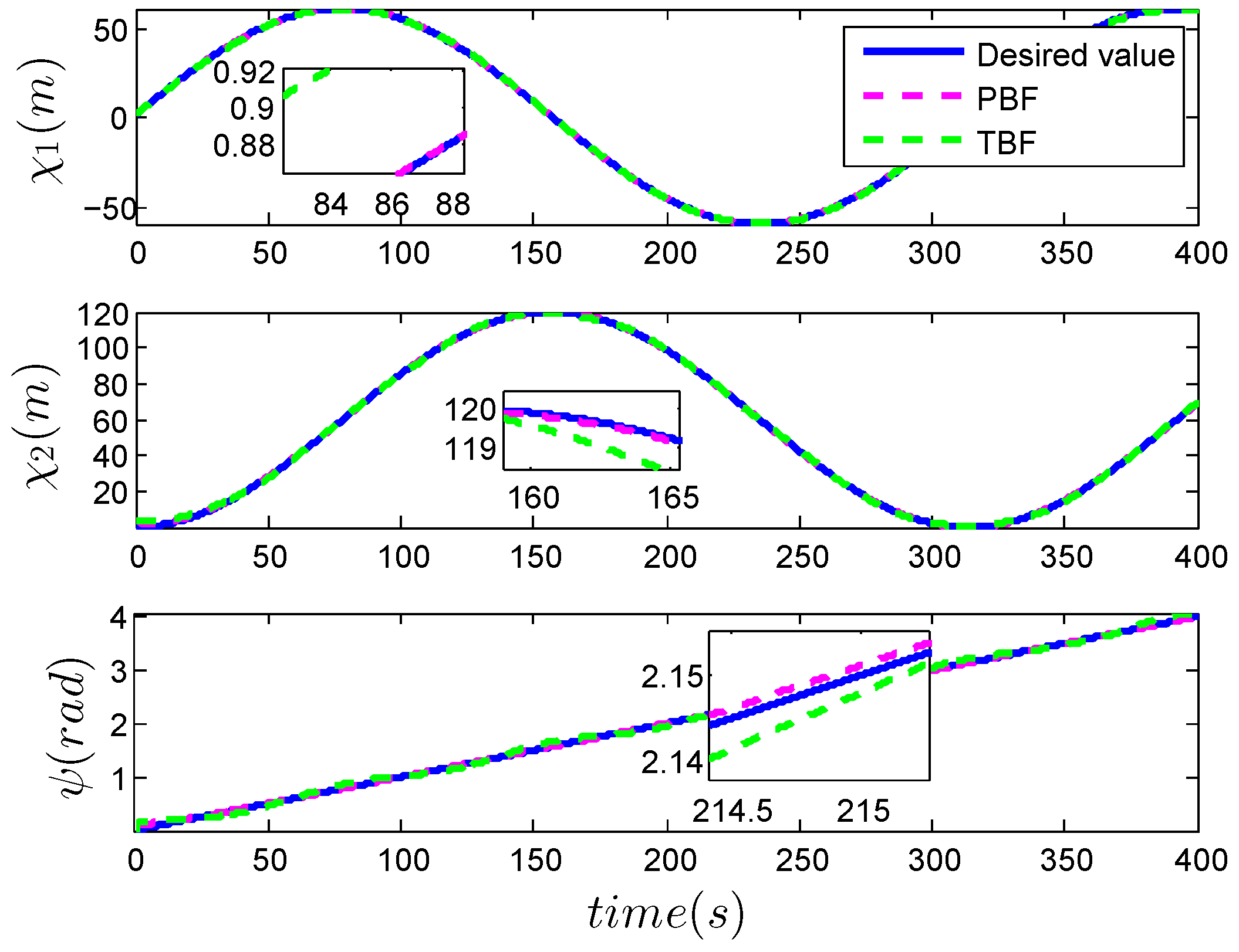
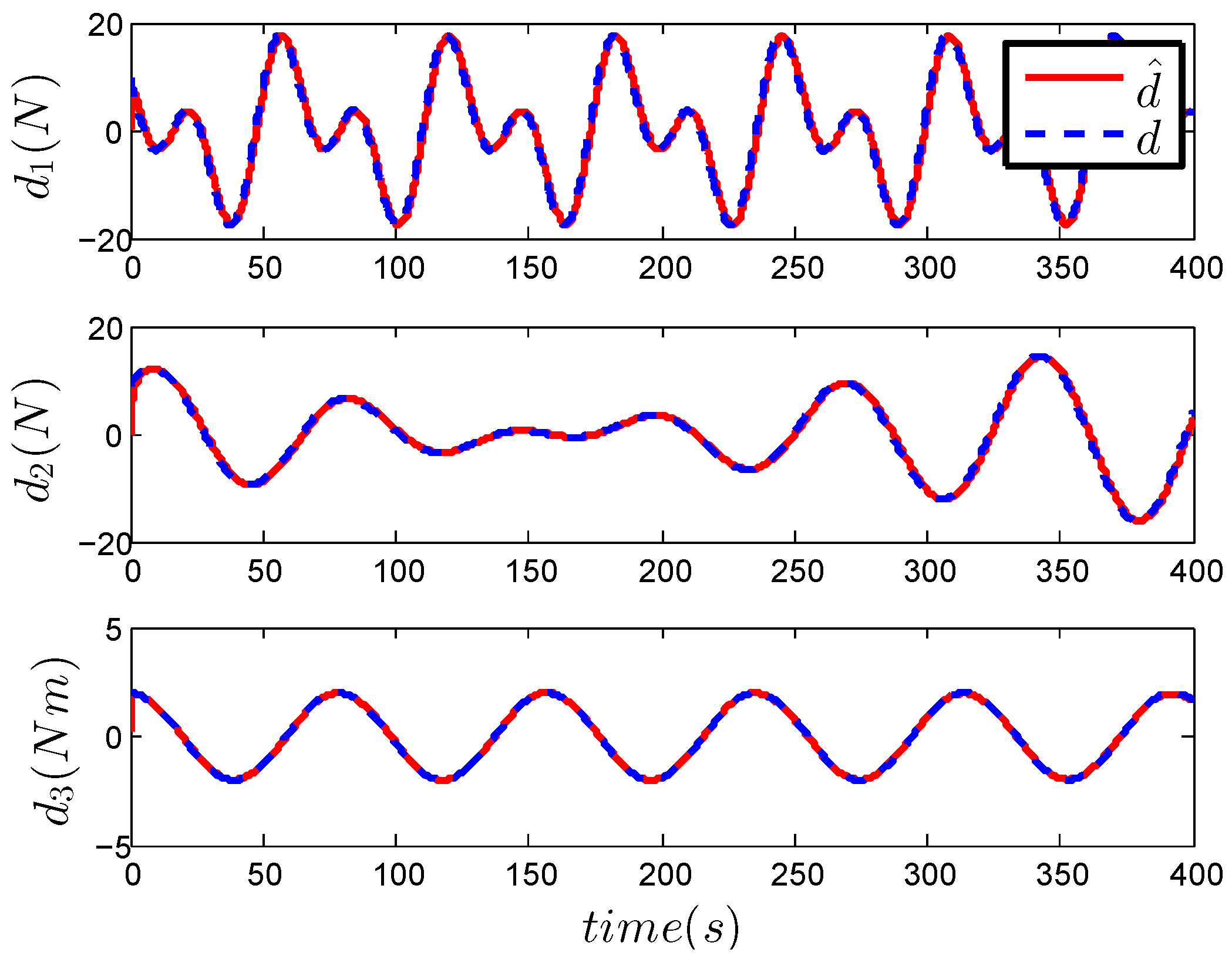
Figure 1, Figure 2, Figure 3, Figure 4 and Figure 5 describe the results of the comparison simulation of two vessel tracking approaches based on the proposed asymmetric barrier function and the traditional logarithmic barrier function. As depicted in Figure 1, both approaches drive the vessel to follow the set trajectory, whereas the devised method can track the set trajectory with higher precision because the traditional asymmetric barrier function-based method does not use the simplified observer to deal with ocean disturbances. In Figure 2, the upper and lower wavy lines in the subfigure represent the constraint boundaries of positional errors. It is easy to see that the position error z 1 always remains within the constraint boundary under the two control strategies. It should be known that the constraint problem dealt with in this article is about X-axis asymmetry. If the constraint is changed to a symmetric constraint, that is, the constraint boundary is symmetric with respect to the X-axis, then our proposed barrier function is still valid, and the traditional barrier function becomes invalid.It should be highlighted that the main difference between the asymmetric barrier function currently in use and the universal barrier function suggested in this article is that the latter multiplies the boundary function k i ( t ) before the current logarithmic function. Correspondingly, the two barrier functions have the same constraint ability when dealing with asymmetric constraint problems. As a consequence, the position error does not cross the envelope boundary under control based on traditional barrier functions, even if the ocean disturbances are not processed. However, if the constraint requirements are eliminated, traditional asymmetric barrier functions cannot be utilized to design controllers for the system. Figure 3 illustrates the performance curve of tracking user-set values for each component of the position vector. Similarly, constraint control methods based on disturbance observers have a higher tracking accuracy. The estimation curve of ocean disturbance d ( t ) by the improved observer is depicted in Figure 4, and it can be seen that the estimation effect is good. The curves of the control input are given in Figure 5. As we can see, the control inputs under both control methods are almost the same, except that there is a significant difference in the initial phase. Finally, according to the simulation results, it can be concluded that the devised barrier function has the same constraint ability as the now available logarithmic barrier function when dealing with asymmetric constraints that vary over time.
Remark 6. 
The simulation offers a study case of applying barrier functions to asymmetric constraint situations that vary over time, but it offers no simulation case for symmetric constraints or situations in which constraints tend to infinity, i.e., when the vessel is not subject to constraint requirements. However, when the constraint situations are altered to time-varying symmetric forms, the simulation scenario will be similar to Case 1 of the authors’ previous research in [51]. The simulation results will be the same as in Case 2 of [51], when the constraint functions k u , i and k l , i trend to infinity. As a result, this paper will not provide excessive simulation examples to demonstrate the universality of the devised barrier function.

5. Conclusions

In this article, a universal asymmetric barrier function-based trajectory tracking control approach is pointed out for a marine vessel subject to asymmetric constraints and ocean disturbances. In this control approach, the novel universal barrier function is employed to cope with the time-varying position error constraints. Moreover, it is theoretically proven that the devised barrier function can deal with more general types of constraint problems compared with the logarithmic barrier function used now. The improved observer is utilized to estimate the ocean disturbances. Thanks to the provided Theorem 1, it can be proven that all error variables, including constrained errors, are exponentially stable. The comparative simulations show that good tracking control performance is achieved. Considering that actuator saturation problems often arise with constraint control, adaptive control technology-based tracking control for marine vessels with input saturation issues will be studied in our future works.

Author Contributions

Conceptualization, T.Z.; investigation, J.Z.; methodology, T.Z.; resources, T.Z.; software, T.Z.; validation, J.Z.; writing—original draft preparation, G.Z.; writing—review & editing, J.Z. All authors have read and agreed to the published version of the manuscript.

Funding

This work was supported by the Scientific Research Projects of Universities Grant No. 2022AH051674, the Forestry and Smart Equipment Scientific Research and Innovation Team under Grant No. 2022AH010091, and the Scientific Research Project of High-Level Talents under Grant Nos. WGKQ2022052 and WGKQ2022006.

Institutional Review Board Statement

Not applicable.

Informed Consent Statement

Not applicable.

Data Availability Statement

The data presented in this study are available on request from the corresponding author.

Conflicts of Interest

The authors declare no conflicts of interest.

References

  1. Donaire, A.; Romero, J.G.; Perez, T. Trajectory tracking passivity-based control for marine vehicles subject to disturbances. J. Frankl. Inst. 2017, 354, 2167–2182. [Google Scholar] [CrossRef]
  2. Ellenrieder, K.D. Dynamic surface control of trajectory tracking marine vehicles with actuator magnitude and rate limits. Automatica 2019, 105, 433–442. [Google Scholar] [CrossRef]
  3. Li, M.-Y.; Xie, W.-B.; Wang, Y.-L.; Hu, X. Prescribed performance trajectory tracking fault-tolerant control for dynamic positioning vessels under velocity constraints. Appl. Math. Comput. 2022, 431, 127348. [Google Scholar] [CrossRef]
  4. Li, M.-Y.; Xu, J.; Xie, W.-B.; Wang, H.-B. Finite-time composite learning control for trajectory tracking of dynamic positioning vessels. Ocean Eng. 2022, 262, 112288. [Google Scholar] [CrossRef]
  5. Bidikli, B.; Tatlicioglu, E.; Zergeroglu, E. Observer-based adaptive output feedback tracking control of dynamically positioned surface vessels. J. Mar. Sci. Technol. 2017, 22, 376–387. [Google Scholar] [CrossRef]
  6. Lin, Y.; Du, J.; Zhu, G.; Fang, H. Thruster fault-tolerant control for dynamic positioning of vessels. Appl. Ocean Res. 2018, 80, 118–124. [Google Scholar] [CrossRef]
  7. ⌀veraas, H.; Halvorsen, H.S.; Landstad, O.; Smines, V.; Johansen, T.A. Dynamic Positioning Using Model Predictive Control with Short-Term Wave Prediction. IEEE J. Ocean. Eng. 2023, 48, 1065–1077. [Google Scholar]
  8. Caharija, W.; Pettersen, K.Y.; Bibuli, M.; Calado, P.; Zereik, E.; Braga, J.; Gravdahl, J.T.; Sorensen, A.J.; Milovanovic, M.; Bruzzone, B. Integral line-of-sight guidance and control of underactuated marine vehicles: Theory, simulations, and experiments. IEEE Trans. Control Syst. Technol. 2016, 24, 1623–1642. [Google Scholar] [CrossRef]
  9. Gonzalez-Garcia, A.; Barragan-Alcantar, D.; Collado-Gonzalez, I.; Garrido, L. Adaptive dynamic programming and deep reinforcement learning for the control of an unmanned surface vehicle: Experimental results. Control Eng. Pract. 2021, 111, 1623–1642. [Google Scholar] [CrossRef]
  10. Zheng, Z. Moving path following control for a surface vessel with error Constraint. Automatica 2020, 118, 109040. [Google Scholar] [CrossRef]
  11. Ma, Y.; Liu, Z.; Wang, T.; Song, S.; Xiang, J.; Zhang, X. Multi-model predictive control strategy for path-following of unmanned surface vehicles in wide-range speed variations. Ocean Eng. 2024, 295, 116845. [Google Scholar] [CrossRef]
  12. Peng, Z.; Wang, C.; Yin, Y.; Wang, J. Safety-certified constrained control of maritime autonomous surface ships for automatic berthing. IEEE Trans. Veh. Technol. 2023, 72, 8541–8552. [Google Scholar] [CrossRef]
  13. Shojaei, K. Observer-based neural adaptive formation control of autonomous surface vessels with limited torque. Robot. Auton. Syst. 2016, 78, 83–96. [Google Scholar] [CrossRef]
  14. Jin, X. Fault tolerant finite-time leader-follower formation control for autonomous surface vessels with LOS range and angle constraints. Automatica 2016, 68, 228–236. [Google Scholar] [CrossRef]
  15. Tran, Q.V.; Lee, C.; Kim, J.; Nguyen, H.Q. Robust bearing-based formation tracking control of underactuated surface vessels: An output regulation approach. IEEE Trans. Control Netw. Syst. 2023, 10, 2048–2059. [Google Scholar] [CrossRef]
  16. Jiang, Y.; Liu, Z.; Chen, F. Adaptive output-constrained finite-time formation control for multiple unmanned surface vessels with directed communication topology. Ocean Eng. 2024, 292, 116552. [Google Scholar] [CrossRef]
  17. Abdelaal, M.; Franzle, M.; Hahn, A. Nonlinear Model Predictive Control for trajectory tracking and collision avoidance of underactuated vessels with disturbances. Ocean Eng. 2018, 160, 168–180. [Google Scholar] [CrossRef]
  18. Kinjo, L.M.; Menard, T.; Wirtensohn, S.; Gehan, O.; Reuter, J. Tracking Control of Docking Maneuvers for a Fully Actuated Surface Vessel Using Backstepping. IEEE Trans. Control Syst. Technol. 2024, 32, 1920–1927. [Google Scholar] [CrossRef]
  19. Aguilar-Ibanez, C.; Suarez-Castanon, M.S.; Garcia-Canseco, E.; Robio, J.J.; Barron-Fernandez, R.; Martinez, J.C. Trajectory Tracking Control of an Autonomous Vessel in the Presence of Unknown Dynamics and Disturbances. Mathematics 2024, 12, 2239. [Google Scholar] [CrossRef]
  20. Manzanilla, A.; Ibarra, E.; Salazar, S.; Zamora, A.E.; Lozano, R.; Munoz, F. Super-twisting integral sliding mode control for trajectory tracking of an Unmanned Underwater Vehicle. Ocean Eng. 2021, 234, 109164. [Google Scholar] [CrossRef]
  21. Londhe, P.S.; Patre, B.M. Adaptive fuzzy sliding mode control for robust trajectory tracking control of an autonomous underwater vehicle. Intel. Serv. Robot. 2019, 12, 87–102. [Google Scholar] [CrossRef]
  22. Elmokadem, T.; Zribi, M.; Youcef-Toumi, K. Terminal sliding mode control for the trajectory tracking of underactuated Autonomous Underwater Vehicles. Ocean Eng. 2017, 129, 613–625. [Google Scholar] [CrossRef]
  23. Sun, Z.; Zhang, G.; Yang, J.; Zhang, W. Research on the sliding mode control for underactuated surface vessels via parameter estimation. Nonlinear Dyn. 2018, 91, 1163–1175. [Google Scholar] [CrossRef]
  24. Zhang, C.; Yu, S. Disturbance observer-based prescribed performance super-twisting sliding mode control for autonomous surface vessels. ISA Trans. 2023, 135, 13–22. [Google Scholar] [CrossRef] [PubMed]
  25. Wen, G.; Ge, S.S.; Chen, C.P.; Tu, F.; Wang, S. Adaptive tracking control of surface vessel using optimized backstepping technique. IEEE Trans. Cybern. 2018, 49, 3420–3431. [Google Scholar] [CrossRef]
  26. Jiao, J.; Wang, G. Event driven tracking control algorithm for marine vessel based on backstepping method. Neurocomputing 2016, 207, 669–675. [Google Scholar] [CrossRef]
  27. Fetzer, K.L.; Nersesov, S.; Ashrafiuon, H. Full-state nonlinear trajectory tracking control of underactuated surface vessels. J. Vib. Control 2013, 26, 1286–1296. [Google Scholar] [CrossRef]
  28. Chen, X.; Tan, W.W. Tracking control of surface vessels via fault-tolerant adaptive backstepping interval type-2 fuzzy control. Ocean Eng. 2020, 70, 97–109. [Google Scholar] [CrossRef]
  29. Shen, Z.; Li, A.; Li, L.; Yu, H. Prescribed performance LOS guidance-based dynamic surface path following control of surface vessel with position and heading errors constraint. J. Navig. 2013, 76, 255–285. [Google Scholar] [CrossRef]
  30. Zhang, J.; Sun, T.; Liu, Z. Robust model predictive control for path-following of underactuated surface vessels with roll constraints. Ocean Eng. 2017, 143, 125–132. [Google Scholar] [CrossRef]
  31. Cui, S.; Zhao, T. Uncertain surface vessels tracking control based on linear active disturbance rejection control and finite time convergence. Ocean Eng. 2024, 298, 117263. [Google Scholar] [CrossRef]
  32. Zhang, L.; Zheng, Y.; Huang, B.; Su, Y. Finite-time trajectory tracking control for under-actuated unmanned surface vessels with saturation constraint. Ocean Eng. 2022, 249, 110745. [Google Scholar] [CrossRef]
  33. Zhang, J.; Yu, S.; Yan, Y. Fixed-time extended state observer-based trajectory tracking and point stabilization control for marine surface vessels with uncertainties and disturbances. Ocean Eng. 2019, 186, 106109. [Google Scholar] [CrossRef]
  34. Zhang, J.; Yu, S.; Wu, D.; Yan, Y. Nonsingular fixed-time terminal sliding mode trajectory tracking control for marine surface vessels with anti-disturbances. Ocean Eng. 2020, 217, 108158. [Google Scholar] [CrossRef]
  35. Yan, Z.; Wang, J. Model predictive control for tracking of underactuated vessels based on recurrent neural networks. IEEE J. Ocean. Eng. 2012, 37, 717–726. [Google Scholar] [CrossRef]
  36. Zhu, G.; Du, J.; Kao, Y. Robust adaptive neural trajectory tracking control of surface vessels under input and output constraints. J. Frankl. Inst. 2020, 357, 8591–8610. [Google Scholar] [CrossRef]
  37. Zhou, B.; Huang, B.; Su, Y.; Zheng, Y.; Zheng, S. Fixed-time neural network trajectory tracking control for underactuated surface vessels. Ocean Eng. 2021, 236, 109416. [Google Scholar] [CrossRef]
  38. Li, M.; Long, Y.; Li, T.; Bai, W. Observer-based adaptive fuzzy event-triggered path following control of marine surface vessel. Int. J. Fuzzy Syst. 2021, 23, 2021–2036. [Google Scholar] [CrossRef]
  39. Tee, K.P.; Ge, S.S.; Tay, E.H. Barrier Lyapunov functions for the control of output-constrained nonlinear systems. Automatica 2009, 45, 918–927. [Google Scholar] [CrossRef]
  40. Tee, K.P.; Ren, B.; Ge, S.S. Control of nonlinear systems with time-varying output constraints. Automatica 2011, 47, 2511–2516. [Google Scholar] [CrossRef]
  41. Zhang, S.; Dong, Y.; Ouyang, Y.; Yin, Z.; Peng, K. Adaptive neural control for robotic manipulators with output constraints and uncertainties. IEEE Trans. Neural Netw. Learn. Syst. 2018, 29, 5554–5564. [Google Scholar] [CrossRef] [PubMed]
  42. Xia, J.; Zhang, Y.; Yang, C.; Wang, M.; Annamalai, A. An improved adaptive online neural control for robot manipulator systems using integral Barrier Lyapunov functions. Int. J. Syst. Sci. 2019, 50, 638–651. [Google Scholar] [CrossRef]
  43. Yu, X.; He, W.; Li, H.; Sun, J. Adaptive fuzzy full-state and output-feedback control for uncertain robots with output constraint. IEEE Trans. Syst. Man Cybern. Syst. 2020, 51, 6994–7007. [Google Scholar] [CrossRef]
  44. Yin, Z.; He, W.; Yang, C. Tracking control of a marine surface vessel with full-state constraints. Int. J. Syst. Sci. 2017, 48, 535–546. [Google Scholar] [CrossRef]
  45. Qin, H.; Li, C.; Sun, Y.; Wang, N. Adaptive trajectory tracking algorithm of unmanned surface vessel based on anti-windup compensator with full-state constraints. Ocean Eng. 2020, 200, 106906. [Google Scholar] [CrossRef]
  46. McIlvanna, S.; Van, M.; Sun, Y.; Naeem, W.; Liu, Z. Adaptive fixed-time control for uncertain surface vessels with output constraints using barrier Lyapunov function. Ocean Eng. 2024, 116740. [Google Scholar] [CrossRef]
  47. Thanh, P.N.N.; Thuyen, N.A.; Anh, H.P.H. Adaptive fuzzy 3-D trajectory tracking control for autonomous underwater vehicle (AUV) using modified integral barrier lyapunov function. Ocean Eng. 2023, 283, 115027. [Google Scholar] [CrossRef]
  48. Li, L.; Dong, K.; Guo, G. Trajectory tracking control of underactuated surface vessel with full state constraints. Asian J. Control 2021, 23, 1762–1771. [Google Scholar] [CrossRef]
  49. Qin, H.; Li, C.; Sun, Y.; Li, X.; Du, Y.; Deng, Z. Finite-time trajectory tracking control of unmanned surface vessel with error constraints and input saturations. J. Frankl. Inst. 2020, 357, 11472–11495. [Google Scholar] [CrossRef]
  50. He, W.; Yin, Z.; Sun, C. Adaptive neural network control of a marine vessel with constraints using the asymmetric barrier Lyapunov function. IEEE Trans. Cybern. 2016, 47, 1641–1651. [Google Scholar] [CrossRef]
  51. Zhang, T.; Zhang, J.; Wang, D.; Fang, J.; Chen, R. Design of trajectory tracking controller for surface vessels with/without output limitations. Ocean Eng. 2024, 307, 118207. [Google Scholar] [CrossRef]
  52. Zhang, T.; Wang, D.; Zhang, J.; Yan, P. Improved Barrier Function with Adjustable Parameter-based Tracking Control for Robot under Position Constraints. IEEE Access 2023, 11, 100137–100145. [Google Scholar] [CrossRef]
  53. Zheng, Z.; Jin, C.; Zhu, M.; Sun, K. Trajectory tracking control for a marine surface vessel with asymmetric saturation actuators. Robot. Auton. Syst. 2017, 97, 83–91. [Google Scholar] [CrossRef]
  54. Zheng, Z.; Sun, L. Path following control for marine surface vessel with uncertainties and input saturation. Neurocomputing 2016, 177, 158–167. [Google Scholar] [CrossRef]
Figure 1. Surface vessel’s tracking performance.
Jmse 12 01545 g001
Figure 2. Constrained position error.
Jmse 12 01545 g002
Figure 3. Position trajectory.
Jmse 12 01545 g003
Figure 4. Disturbance trajectory.
Jmse 12 01545 g004
Figure 5. Control input.
Jmse 12 01545 g005
Disclaimer/Publisher’s Note: The statements, opinions and data contained in all publications are solely those of the individual author(s) and contributor(s) and not of MDPI and/or the editor(s). MDPI and/or the editor(s) disclaim responsibility for any injury to people or property resulting from any ideas, methods, instructions or products referred to in the content.