Article

Hydroelasto-Plastic Response of a Ship Model in Freak Waves: An Experimental and Numerical Investigation

1
Key Laboratory of High Performance Ship Technology (Wuhan University of Technology), Ministry of Education, Wuhan 430063, China
2
Departments of Ocean Engineering, School of Naval Architecture, Ocean and Energy Power Engineering, Wuhan University of Technology, Wuhan 430063, China
3
Department of Ocean Science and Engineering, Southern University of Science and Technology, Shenzhen 518055, China
*
Author to whom correspondence should be addressed.
J. Mar. Sci. Eng. 2024, 12(9), 1555; https://doi.org/10.3390/jmse12091555
Submission received: 27 July 2024 / Revised: 25 August 2024 / Accepted: 27 August 2024 / Published: 5 September 2024

Abstract

:
Freak waves have caused numerous accidents resulting in the collapse of ship structures due to structural plasticity, buckling, and instability, leading to the loss of life and property. Consequently, there is a growing academic interest in understanding ship structural collapsed responses induced by freak waves. This paper presents both numerical and experimental investigations on the structural collapse response of a ship model caused by freak waves. The study uses the Peregrine breather solution theory based on the Nonlinear Schrödinger (NLS) equation to generate a theoretical freak wave, and the nonlinear time-domain wave elevation and velocity field are obtained. The theoretical history of wave elevation is transferred into the wave maker of the wave tank to create experimental freak waves, and the velocity field of the freak wave is defined in a Computational Fluid Dynamics (CFD) solver to generate 3D numerical freak waves. A similar hydroelasto-plastic model is designed, and a hydroelasto-plastic experiment is conducted to observe experimental freak waves and large rotational deformations. The theoretical velocity field from the Peregrine breather solution theory, based on the NLS equation, is defined in a CFD platform to generate 3D numerical freak waves. A two-way Fluid-Structure Interaction (FSI) numerical hydroelasto-plastic approach coupling of CFD with a nonlinear Finite Element Method (FEM) solver is applied. Co-simulation of wave pressures and the structural collapsed response of the ship model caused by freak waves is performed. The wave elevation of experimental and numerical freak waves and the large rotational deformation of the buckling hinge are analyzed and compared, revealing a good agreement between the experiment and calculation. The maximum simulation rotational angle is 38.9°, while the maximum experimental rotational angle is equal to 42.3° for a typical wave case H2, which means numerical model accuracy and performance are acceptable for the simulating hydroelasto-plastic problem. The findings demonstrate that the numerical approach proposed in this study can effectively solve the hydroelasto-plastic response of ship structures in freak waves, offering a valuable tool for evaluating ship strength in these conditions and guiding future ship structural design.

1. Introduction

1.1. Background

Freak wave, often referred to as ‘extreme wave’ or ‘rogue wave’, are defined with greater precision by Haver as a wave with a height more than twice the significant wave height [1,2]. Unlike regular wave trains, a freak wave represents a singular occurrence characterized by an extraordinary wave height. The magnitude of large freak waves can sometimes reach a height of 20 m or even 50 m. Perhaps the most well-known example of a freak wave is the ‘New Year wave’, which achieved a remarkable 25.6 m in height and was recorded by the Draupner oil platform in 1995 [3]. The term ‘freak wave’ continues to be used synonymously with ‘rogue wave’ in various research contexts.
Freak wave, characterized by their immense height, pose significant threats to ocean-going ship structures and human safety, having been the cause of numerous maritime disasters worldwide. The large wave loads and energy associated with such huge wave heights have the potential to collapse slender girders and fracture the vessel. Gunson et al. [4] documented several ship structural accidents occurring between 1995 and 1999 due to severe weather conditions, resulting in the loss of almost 542 lives globally, as recorded in Lloyd’s global database and Lloyd’s casualty reports, which are widely recognized as the most typical examples of such incidents. Specific examples include the impact of a freak wave on the Norwegian Wilstar tanker in the South Africa Sea in 1974, causing severe damage to the bow [5]. The breaking and subsequent sinking of a Japanese container ship carrying 7000 TEUs on the Asia-Europe route on 17 June 2013 [6]. And the breaking of the Ukrainian bulk carrier ‘ARVIN’ into two parts after encountering large waves in the Black Sea led to the death of 3 sailors and the disappearance of another 3 [7]. Over the last 25 years, approximately 22 carriers have experienced impacting accidents due to freak waves.
Therefore, understanding the interactive mechanism between freak waves and ship structure is of paramount importance. The collapse of a ship structure caused by a freak wave is a complex nonlinear Fluid-Structure Interaction (FSI) problem. Ship structure may generate structural nonlinearities such as plasticity, buckling, and instability as long as the structure encounters large freak waves as many researchers call the structural nonlinearities as collapsed response. As the ship structure collapses, it generates significant deformation of the wet surface, and this large deformation, in turn, can affect wave loads and pressure. Consequently, addressing the intricate relationship between structural collapsed response and wave pressure necessitates a cooperative approach that leverages the FSI method.

1.2. Recent Studies on Hydroelasto-Plasticity Generated by Freak Waves

1.2.1. Generation of Freak Wave

The generation of freak waves is a fundamental prerequisite for simulating ship structural collapse caused by rouge waves. Freak waves can be generated both in wave tanks and through numerical approaches. The primary principles for generating freak waves include wave superposition and the theory of the Non-Linear Schrödinger equation.
Waves-superposition is a basic principle to create freak waves in both wave tanks and numerical simulations. Wave superposition involves the overlay of a single wave and a wave train, generating a freak wave when their wave crests coincide. However, this superposition only occurs at special positions and moments. Kriebe et al. [8] proposed a freak wave model superposed by two wave trains, with a pulse overlaid on a wave train. Kim et al. [9] used the back propagation method to generate a freak wave in a 2D wave tank. The tank is equipped with two wavemakers at opposite sides, enabling two waves to spread oppositely and encounter a fixed position to form a larger wave. Sheng et al. [10] improved the freak wave model of two wave trains by adjusting the initial phase of the background wave train to increase wave height. Waseda et al. [11] produced a variety of freak waves using both linear and nonlinear wave generation mechanisms, attributing numerous losses of super-carriers to collisions with freak waves. Although wave superposition provides an approach to generating freak waves, it only occurs at special positions and times, and the freak wave is considered a linear wave model. This approach does not sufficiently explain the nonlinearities of rouge waves.
An alternative approach for generating rouge waves involves utilizing a Non-Linear Schrödinger (NLS) equation to obtain numerical solutions. This approach has been explored by various researchers. Hu et al. [12] conducted a series of simulations on freak waves using the breather solution of the cubic Schrödinger equation within a numerical wave tank. They compared the simulated results with theoretical solutions and validated the breather solutions by simulating a realistic freak wave measured in the Sea of Japan under actual sea conditions. Chabchoub et al. [13] created freak waves in the laboratory using the breather solutions of the cubic NLS equation for deep water conditions. Zakharov et al. [14] performed numerical simulations of freak waves, considering both the modulation instability of wave trains and the evolution of NLS solutions. Didenkulova et al. [15] studied the properties of freak waves in intermediate compared to deep waters and found Peregrine breathers contained more individual waves at intermediate depths than in deeper waters.
The generation of freak waves through wave superposition is based on a linear wave model, which fails to capture important nonlinearities inherent in such phenomena. In contrast, the utilization of the NLS equation with breather solutions enables the production of the nonlinearities of freak waves. This approach facilitates the acquisition of nonlinear freak wave elevation, which can be transferred to a wavemaker or a Numerical Wave Tank (NWT). However, if the study focuses on ship structural collapsed responses induced by freak waves, the freak wave information obtained from the NLS equation must be integrated with an FSI solver.

1.2.2. FSI of Freak Wave and Ship Structure

Freak wave, characterized by enormous wave height and energy, exert significant impacts on ship structures, affecting both large motion and structural strength. The study of these effects has drawn extensive attention from researchers, leading to a multitude of investigations on FSI between freak waves and ship structures. Clauss et al. [16] carried out experimental tests with ship models in freak waves. They systematically investigated three segmented ships equipped with force transducers at several cruising speeds and deterministic wave sequences to identify structural loads, Vertical Bending Moment (VBM), and superimposing longitudinal forces. Shi et al. [17] performed a hydroelastic model test of a containership in freak waves, measuring ship motion and VBM and identifying whipping responses within the experiment. Kinoshita et al. [18] carried out a series of towing tests in a wave tank using an elastic container ship model. Their detailed experimental analysis explored longitudinal bending loads and whipping responses caused by bottom and bow flare slamming. They also discussed the influences of various input wave parameters on vertical bending moments and whipping loads. Holst et al. [19] investigated the influence of wave-current interaction on a tidal turbine. They conducted experiments at the Norwegian Marine Technology Research Institute and utilized Computational Fluid Dynamics (CFD) analysis to enhance the understanding of the wave-induced loads on the tidal turbine rotor.
Wang et al. [20] developed a three-dimensional in-house solver to investigate the interaction between freak waves and ship structure. Their approach validated the wave-ship interaction process, providing insights into the motion responses of the ship and the green water loadings induced by the freak waves. Specific analyses were carried out to understand the influences of the freak wave crest and sequence on factors such as roll, heave, and impact pressures. Liu et al. [21] used CFD software STAR-CCM+ 17.04 version to generate freak wave at specified positions and moments. They implemented a time-domain FSI approach, utilizing a combination of CFD and the Finite Element Method (FEM), to simulate the hydroelastic response of an elastic floating body. Their findings highlighted the efficacy of the CFD approach in generating 3D freak waves and demonstrated its compatibility with structural solvers to establish an FSI framework for freak wave and ship structure analysis.
While numerous studies have been conducted worldwide on the interaction between freak wave and ship structures, the structural responses examined have often been limited to linear and elastic behaviors. However, freak waves, with their substantial wave heights, have the potential to generate intense wave loads that may induce structural nonlinearities, including plasticity and buckling. Existing approaches that couple linear FSI with hydrodynamic solvers and linear structural solvers can only address the elastic response of ship structures. These methods fall short of investigating the more complex collapsed response of ship structures, encompassing both plasticity and buckling. To fully understand and model these phenomena, it is necessary to integrate CFD with nonlinear FEM.

1.2.3. Hydroelasto-Plasticity

The concept of hydroelasto-plasticity was first introduced by Masaoka et al. [22] as an innovative approach to studying the structural collapsed response of ship structures caused by waves. Unlike conventional methods, this approach takes into consideration the collapsed response of ship structure, such as the structural plasticity, buckling, and instability that may arise due to large wave actions. Subsequent research has seen the development and application of various hydroelasto-plastic methods. These have significantly expanded the understanding of the structural response and collapse mechanisms of ship structures under the influence of large waves.
Hydroelasto-plasticity can be classified into two types, with the first being potential-flow hydroelasto-plasticity, a method that combines a potential flow solver with a nonlinear structural solver. This approach typically utilizes one-way coupling, where wave pressures are applied to the ship’s structural model but the wet surface deformation of the ship is not transferred back to the hydrodynamic solver. Masaoka et al. [22], for the first time, proposed a method that employs strip theory to calculate wave loads and integrates a nonlinear beam to simulate the ship structure’s girder, thereby determining the nonlinear bending moment. Subsequent applications of this concept include Iijima et al.’s [23] numerical hydroelasto-plastic approach, Lee et al.’s [24] experimental database for CFD validation, Liu et al.’s [25] study of 3D structural collapse via 3D FEM, and Liu et al.’s [26] 2D method using variable rigidity beam. Despite the potential flow hydroelasto-plasticity to address nonlinear structural responses, here are limitations. Specifically, the ship’s body is considered a rigid model, the nonlinearities of wave load cannot be solved within the potential flow solver, and the two-way FSI of wave pressure and structural deformation cannot be realized.
An emerging method for simulating hydroelasto-plasticity is the approach that combines viscous flow with CFD and nonlinear FEM at present. Liu et al. [27] introduced a two-way hydroelasto-plastic method, coupling CFD with nonlinear FEM to model structural nonlinearities, including plasticity and buckling. This study utilized both one-way and two-way simulations, comparing them with hydroelasto-plastic experiments. Their findings revealed that the two-way FSI coupling of CFD and nonlinear FEM produced more accurate results compared to one-way numerical results.
Based on the current research landscape in hydroelasto-plasticity, previous studies have primarily focused on the hydroelasto-plastic responses of ships in regular waves. However, freak waves represent a specific type of large single wave, possessing significant wave height, which has been observed to cause catastrophic structural damage to ships, even breaking them into two parts. Given the destructive nature of freak waves, it is evident that further investigation into the hydroelasto-plastic response of ships caused by freak waves is both a necessary and timely research direction.

1.3. Challenges of Studying Hydroelasto-Plastic Responses Caused by Freak Waves

Freak waves have been known to cause structural collapsed accidents in ship structures across the globe. However, current hydroelasto-plastic research is primarily confined to regular waves. This paper seeks to explore the hydroelasto-plastic response of ship structure in freak waves, and the challenges faced and solved in this pursuit are as follows:
(1)
Generation of freak waves in both experiment and simulation: Both experimental and numerical methods will be used to study the structural collapsed response of ship structure in freak waves. Therefore, freak waves must be generated in the experimental wave tank and integrated into the FSI numerical approach. While waves can be superimposed or constructed using the Peregrine breather solution theory based on the NLS equation, the latter offers a more stable and nonlinear representation of freak waves, making it the preferred method.
(2)
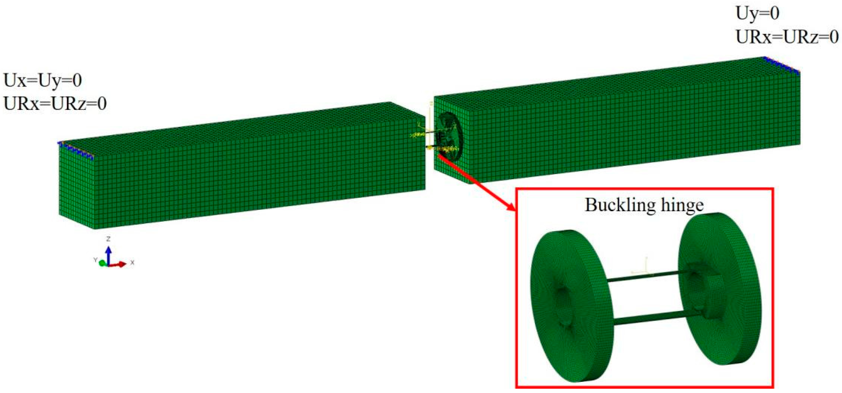
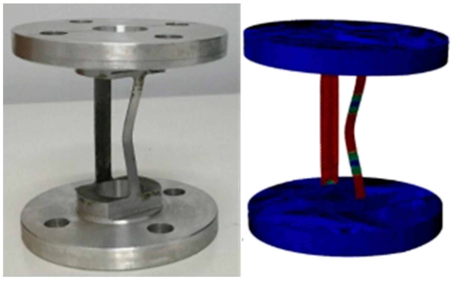
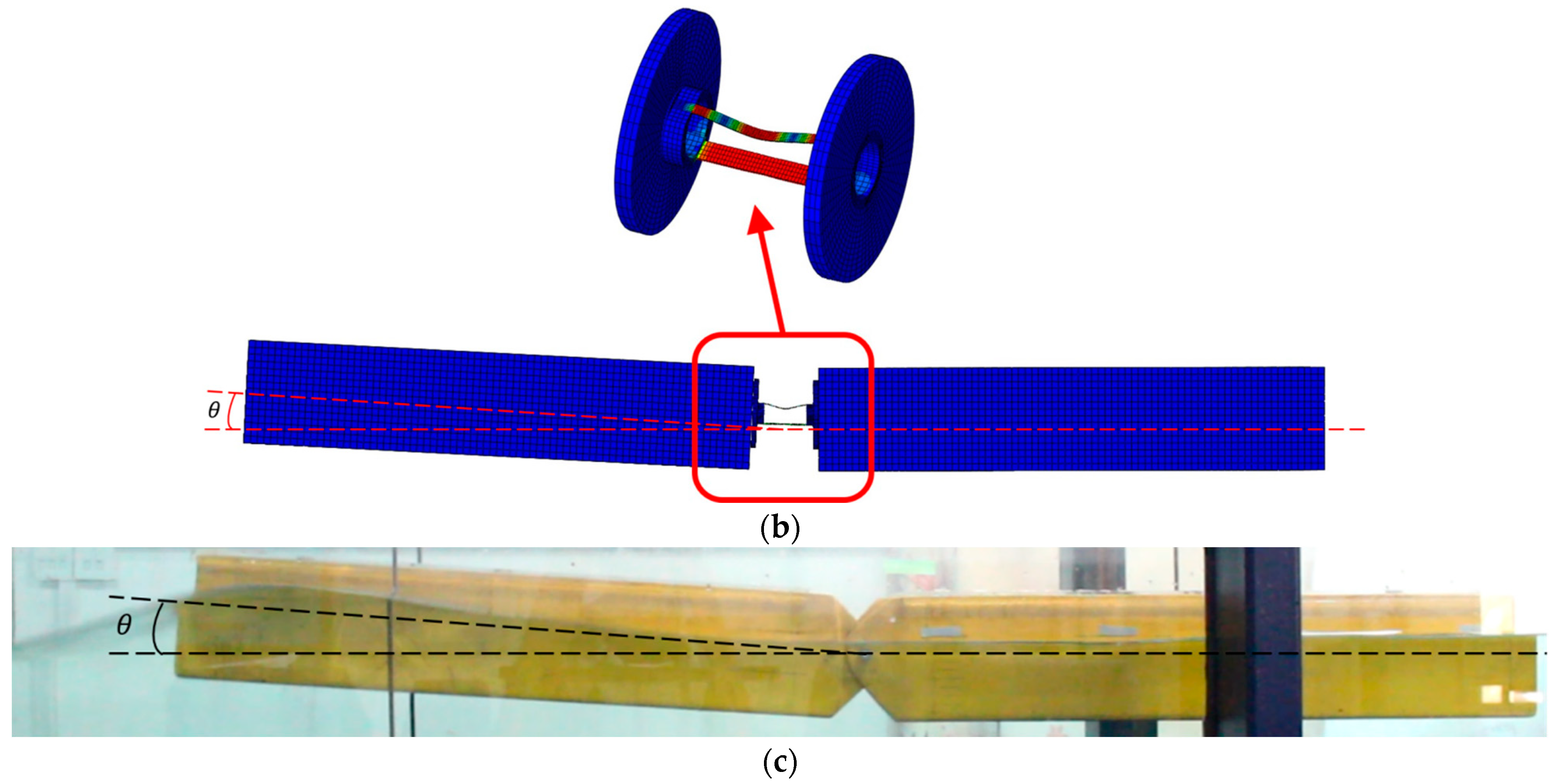
Conducting a hydroelasto-plastic model experiment in freak waves: Any numerical hydroelasto-plastic approach must be validated through a model experiment. Traditional hydroelastic ship structures, which use a beam to test VBM, often struggle with small wave heights, making it difficult to generate a structurally collapsed response. This study proposes a specialized hydroelasto-plastic ship structure with a buckling hinge at midship and rigid strips at the ends, enabling structural collapse simulations. This model differs from previous experiments confined to regular waves [27,28] and represents a novel approach.
(3)
Development of an appropriate FSI numerical approach: CFD platform STAR-CCM+ offers the capability to model nonlinear wave patterns if the velocity field is determined, such as through Peregrine breather solution theory [29]. Additionally, STAR-CCM+ can be combined with the nonlinear FEM solver ABAQUS, considering structural plasticity and instability, to establish a one-way or two-way hydroelasto-plastic numerical approach.
(4)
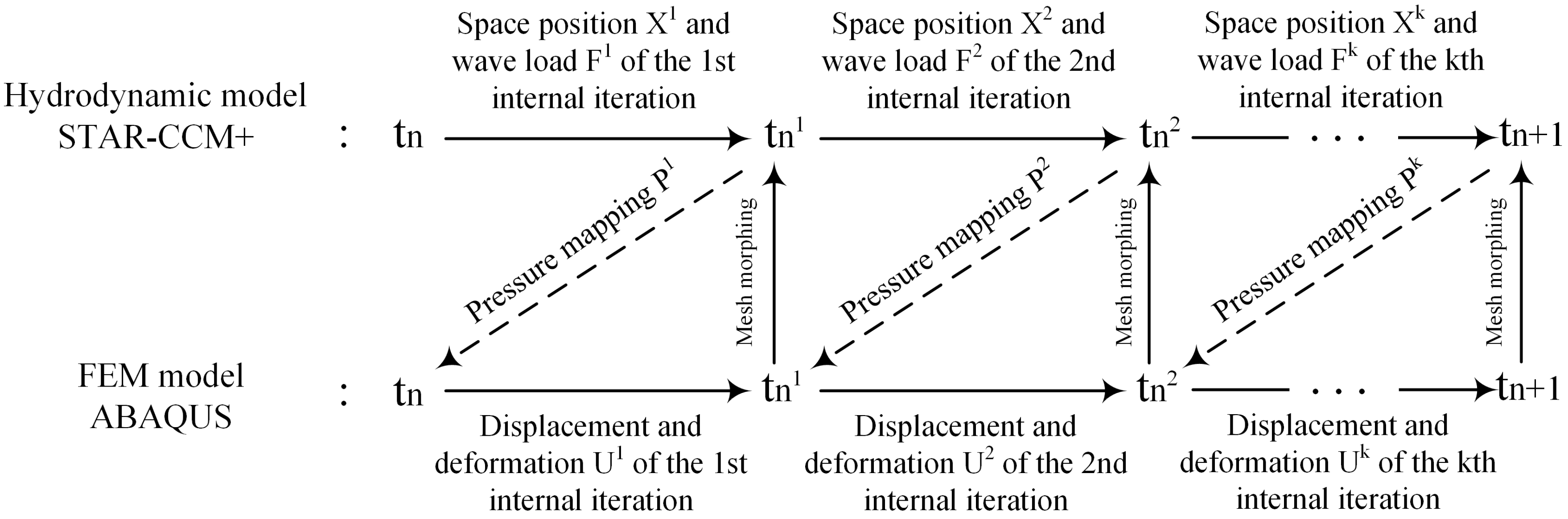
Implementation of two-way FSI of CFD and nonlinear FEM: FSI can be performed as either one-way or two-way coupling. One-way FSI involves a single data transfer, where wave pressures calculated by CFD are applied to the FEM model without considering the effect of structural deformation on fluid pressures. Two-way FSI involves two data transfers, allowing co-simulation of wave pressures and structural nonlinearities, thus considering the effect of both wave load and structural deformation. Previous analysis found two-way FSI to be more accurate than one-way FSI [27], leading to employing two-way FSI in this study.

1.4. Objectives of This Paper

The primary objective of this paper is to develop a hydroelasto-plastic numerical method that can calculate the structural collapsed response of ship structures in freak waves. Liu et al. [27] just used regular waves to study the hydroelasto-plastic response. This paper will integrate Peregrine breather solution theory based on the NLS equation with a two-way FSI approach coupling CFD and nonlinear FEM. The study will employ both experimental and numerical means to investigate the structural collapsed response of ship structures to freak waves. As illustrated in Figure 1, the research route of this paper begins with the application of Peregrine breather solution theory. Utilizing the NLS equation, this theory is used to generate the theoretical solutions for the nonlinear time-domain wave elevation and velocity field of freak waves. Therefore, the wave model and hydroelasto-plastic response studied in this paper are more complicated than Ref. [27].
Secondly, a similar hydroelasto-plastic model as those described in [26,27] is designed and constructed, followed by the execution of a hydroelasto-buckling model experiment. This experiment aims to capture the experimental freak wave and extensive rotational deformation. Utilizing the theoretical time-domain history of wave elevation derived from the Peregrine breather solution theory, the electrical history of the wave maker is calibrated to generate experimental freak waves. Thirdly, this theory is further employed to define the theoretical velocity field of a freak wave within the CFD platform STAR-CCM+, resulting in the generation of 3D numerical freak waves. Fourthly, the CFD solution is combined with a nonlinear FEM solver to establish a two-way FSI numerical approach. This sophisticated simulation enables the co-modeling of wave pressures and structural collapsed responses of the ship structure under the influence of freak waves. In the final stage of analysis, the wave elevations from both experimental and numerical freak waves, along with the substantial rotational deformation of the buckling hinge, are analyzed and compared. The results demonstrate a strong correlation between experimental data and numerical calculations, validating the efficacy of the proposed numerical approach for solving the hydroelasto-plastic response ship structure in freak waves. This study provides valuable insights into evaluating ship strength under such challenging conditions and offers practical guidelines for ship structural design.

2. Hydroelasto-Plastic Model Experiment of a Ship Structure in Freak Waves

In order to verify the effectiveness of numerical methods, a hydroelasto-plastic model experiment is designed and conducted on a ship structure under the influence of freak waves. The experiment seeks to identify the failure mode of the model by measuring significant angular deformations at the midpoint of the ship structure.

2.1. Model Description

The hydroelasto-plastic model test provides a feasible way to study structural collapse in freak waves within laboratory conditions. For this purpose, a specialized hydroelasto-plastic ship structure is designed and fabricated, consisting of a buckling hinge flanked by two rigid bodies, as depicted in Figure 2. The buckling hinge simulates the structural collapse of the structure, while the two ship bodies receive wave loads. Past experiments have employed hydroelasto-plastic models to study such phenomena in regular waves [26,27]. In this study, which focuses on the hydroelasto-plastic response of ship structures in freak waves, a dedicated model experiment is performed. This involves measuring the extensive rotational displacement between the two rigid bodies. Two wireless inclinometers are placed at the middle cabin of each floating body, and the difference in their inclination histories provides the rotational deformation of the hydroelasto-plastic model, as illustrated in Figure 2b. Figure 3 presents schematic diagrams of the model arrangement in the wave tank, conducted at Wuhan University of Technology’s glass wave tank. The wavemaker in the facility can generate a diverse array of waveforms. In the experiment, the model is arranged near the wavemaker, where the focusing freak wave occurs. A wave height gauge is placed parallel to the testing model’s bow, and absorbing wave equipment is located at the tank’s end to eliminate wave reflection.

2.2. Experimental Facilities

An essential component of the hydroelasto-plastic model experiment is the generation of tank freak waves, which are used to induce collapse in the hydroelasto-plastic ship structure. In this paper, the tank freak waves are generated based on nonlinear Schrödinger’s equation, and the experiment is carried out within a glass wave tank at Wuhan University of Technology, as shown in Figure 3. The wave elevation history, considered as the theoretical result, is obtained from the Nonlinear Schrödinger’s equation. Subsequently, this wave elevation function is programmed and incorporated into the control program of the wave maker. This program facilitates the generation of diverse wave types, including regular waves, solitary waves, and customized arbitrary irregular waves. Utilizing the customized wave making program, the freak wave’s surface elevation curve data can be retrieved to control the wave maker, thereby customizing wave generation according to the specific input parameters of the freak wave. A wave elevation gauge is positioned at the focus of the wave, enabling the comparison and analysis of experimental, theoretical, and numerical histories of the freak wave. The consistency observed among these data serves to validate the efficacy of the method.

2.3. Experimental Cases

Seven cases have been identified for the execution of hydroelasto-plastic model experiments, as detailed in Table 1. Four cases, designated as H1–H4, involve variations in wave height while maintaining a consistent ratio of wavelength to the model length of 1. These cases are used to study the effect of freak-wave height on the hydroelasto-plastic response of the structure. Conversely, the cases labeled L2–L4, which alter wavelength while keeping the maximum wave height constant at 110 mm, are used to explore the effect of freak wavelength on the hydroelasto-plastic response of the ship structure. The comprehensive wave parameters for all these cases are given in Table 1.

3. Numerical Methodology

In this study, the nonlinear wave load is simulated based on the CFD method, which allows for the generation of numerical freak waves. An implicit dynamic nonlinear finite element is employed, operating with two-way coupling between fluid and structural domains. This approach ensures an accurate determination of the wave load, taking into consideration the influence of structurally large deformation on the fluid field.

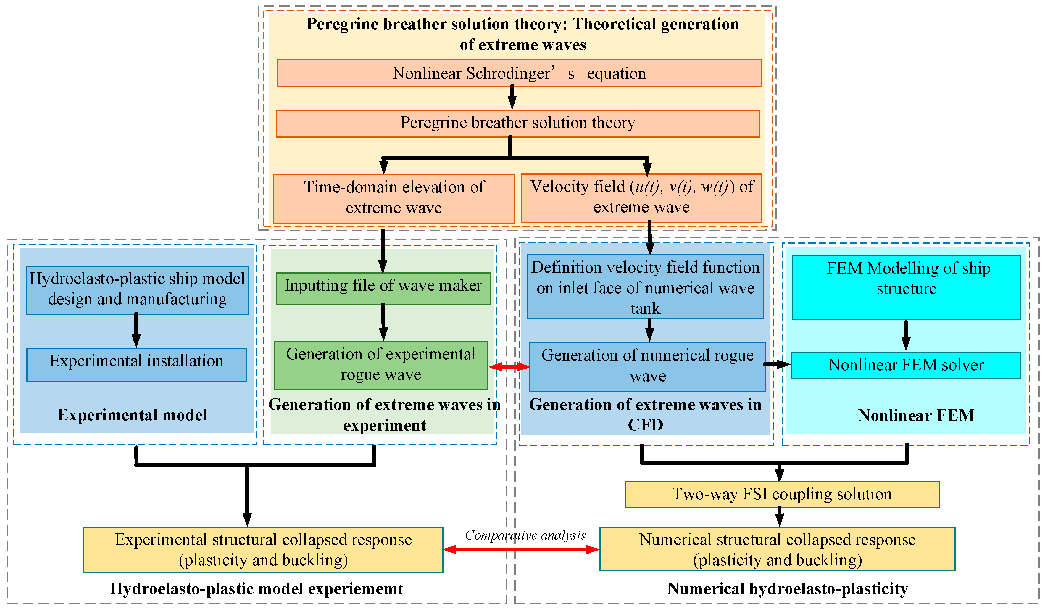
3.1. Hydroelasto-Plastic Numerical Framework

Ship structural collapse under freak waves essentially involves nonlinear fluid-structure coupling. In solving the structural nonlinearities induced by freak waves, this study incorporates two key numerical methodologies: the numerical generation of freak waves and the hydroelasto-plastic approach for FSI analysis. Peregrine breather solution theory, derived from the Nonlinear Schrödinger’s equation, is employed to obtain both the velocity components and wave elevation of the freak wave. These velocity components are then applied on the inlet face of the CFD wave tank to generate the numerical freak wave, while the wave elevation is converted to electric histories for the wave maker to create tank freak waves. Additionally, a numerical hydroelasto-plastic approach that couples CFD and nonlinear FEM is presented, as described by [29]. In Figure 1, the generation of freak waves is simulated using hydrodynamic software STAR-CCM+ (17.04 version) based on the Peregrine breather solution theory derived from the Nonlinear Schrödinger’s equation. Subsequently, this hydrodynamic software is integrated with nonlinear finite element software ABAQUS (2021 version). The coupled numerical simulation method, employing both CFD and FEM, is used to calculate the structural collapsed response under the influence of freak waves.
The numerical approach adopts a co-simulation of CFD and nonlinear FEM, allowing for nuanced modeling of the free liquid surface’s nonlinearity within the numerical flow field. This approach also provides a more authentic representation of the ship structure’s motion in waves, facilitating the acquisition of precise external load data. Through automatic data exchange at the fluid-structure coupling interface, the system ensures an enhanced mapping of wave load between the freak wave and the structure, as well as the efficient transfer of structural deformation. Consequently, this methodology enables the realistic simulation of structural collapse behavior under freak wave conditions.

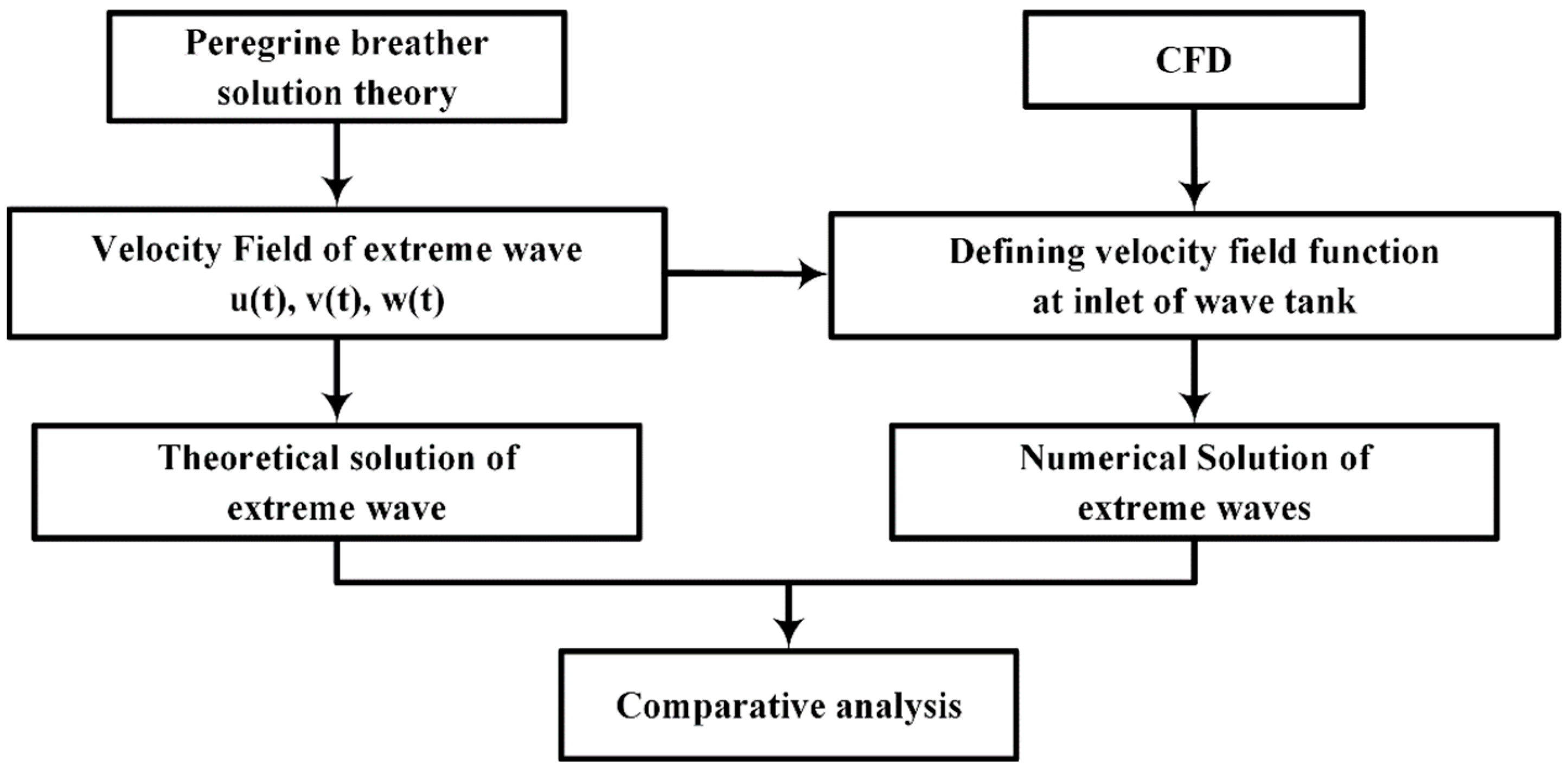
3.2. Peregrine Breather Solution Theory Solved from Nonlinear Schrödinger’s Equation

The Nonlinear Schrödinger’s equation is suitable for describing the evolution of freak waves in cases involving deep or finite water. Solving the hydrodynamics of gravity waves typically involves the Euler equation, but the full nonlinear Euler equation can be complex to resolve, necessitating a simplified numerical model that retains the nonlinearities of the equation. This study employs the Peregrine breather solution theory derived from the Nonlinear Schrödinger’s equation, as proposed by Mei [29].
To obtain the solution, both velocity potential and wave elevation are solved using Taylor series expansion, resulting in the third-order nonlinear Schrödinger’s equation. The expressions for velocity potential and wave elevation are then expanded as follows:
φ = ε φ 10 g cosh Q 2 ω cosh q i A e i ψ + c . c .
ζ = π 2 A e i ψ + c . c .
where ε = k A 0 is a small constant, Q = k z + h , q = k h , ψ = k x ω t , g is the gravity acceleration, and c . c . is the complex conjugate content. The coordinate system is located on the static water surface, z = 0 denotes the static water surface, z = h is the bottom of water, k is the wave number, and ω is circular frequency, satisfying dispersion relation ω 2 = g k tan h k h . φ 10 presents the average flow rate and A is the envelope line of a complex wave of sine wave train.
Peregrine studied the third-order Nonlinear Schrödinger equation, expressed in its standard form as follows:
i η T + η X X + 2 η 2 η = 0
Peregrine expanded the amplitude peak using the Taylor series and derived a solution for the equation. The solution, known as Peregrine breather, can be expressed as follows:
η = η 0 e i η 0 2 T 1 4 1 + 4 i η 0 2 T 1 + 4 η 0 X + 16 η 0 2 T 2
Up to this point, the Peregrine breather equation has been recognized as a solution of the standard nonlinear Schrödinger equation. In order to obtain solutions of Peregrine breather equation as Equation (3), a transform shown in Equation (4) is realized, T = τ , X = α 1 / 2 ξ and η = ( β / 2 ) 1 / 2 A . In this paper, both η and η are solutions of Equation (3). The form of Peregrine breathers used in this study is given as follows:
A = A 0 e i β A 0 2 τ 4 α 1 2 i β A 0 2 τ α + α 2 β A 0 2 τ 2 + 2 β A 0 2 ξ 2 1
The velocity components of the freak wave in the horizontal and vertical directions are given as follows:
u = ε g k cosh Q 2 ω cosh q A e i ψ + c . c .
v = ε g k sinh Q 2 ω cosh q i A e i ψ + c . c .
In this study, the inlet-velocity wave making method is employed to generate a freak wave, effectively reducing the effect of the inlet grid on wave making, thereby generating high-precision freak wave representation. This method utilizes the known water particle velocity and the function of wave elevation to define the velocity distribution at the inlet. For the numerical freak wave, Peregrine breather solution theory, obtained from the nonlinear Schrödinger equation as expressed in Equations (6) and (7), is defined on the inlet face, serving as the basis for the freak wave generation.

3.3. Nonlinear FEM

Liu et al. [28] proposed a numerical hydroelasto-plastic approach that couples CFD and nonlinear FEM to investigate the structural collapse of ship structure caused by waves. Within this framework, CFD is employed to model the model’s hydrodynamics and seakeeping, from which wave loads are calculated. Nonlinear FEM is then used to model ship structure, with wave loads calculated by CFD transferred to the outer shell elements of the wetted ship surface. The structural collapsed response of the ship, including plasticity and buckling, is solved using the Newton–Raphson method. Both one-way and two-way coupling schemes can be iterated to obtain the wave pressure and extensive structural deformation. However, Liu et al. [29] have confirmed that the two-way coupling scheme offers superior precision in solving hydroelasto-plasticity problems compared to one-way coupling. Therefore, this paper employs the two-way coupling scheme to determine the structural collapsed response of the ship structure under freak waves. The relevant numerical methodology is introduced as follows:
The structural collapse of a ship, encompassing phenomena such as plasticity and buckling, necessitates a sophisticated numerical solution. In this study, the Newton–Raphson method is used to iterate the nonlinear FEM equations.

3.4. Two-Way Hydroelasto-Plastic Coupling CFD and Nonlinear FEM

FSI executes an interactional iterative solution between fluid mechanics and solid mechanics, focusing on the deformation and dynamic properties of solid structure under the influence of fluids, as well as the reciprocal effects on fluid dynamics. In scenarios where a solid structure undergoes noticeable deformation due to fluid forces, and this deformation, in turn, affects the flow characteristics of the fluid, the interaction between the solid and the fluid cannot be ignored. Such a reciprocal relationship is termed ‘two-way coupling’. In two-way coupling simulations, data transfer occurs at each iterative step, fluid calculations provide information on pressure, velocity, and other relevant parameters, while solid calculations contribute nodal displacement data. Upon the completion of each iterative step; the results in both the structural and fluid domains are acquired.
In this study, a two-way implicit coupling simulation is achieved through the coordinated interplay between a CFD platform and a nonlinear FEM platform, enabled by the exchange of pressure and nodal displacement data across the fluid-solid coupling interface. The complex procedure necessitates the precise transmission of data on the two-way coupling boundary, thus requiring adherence to the basic conservation law at the fluid-structure interface. The selection of data types and transmission methods is critical to resolving the intricate interplay between CFD and FEM. Figure 4 illustrates the data exchange diagram for bidirectional fluid-solid coupling within an iterative time step. Initially, the structural displacement at time t n is calculated according to the flow field domain’s initial values within a singular coupling step. This initial value is then transferred to CFD at a time t n through the designated FSI interface, facilitating the object’s deformation and motion. Subsequently, the flow field distribution at a time t n + 1 is obtained by resolving it within the flow field domain. This new flow field value is transferred back to FEM, and the structural response at a time t n + 1 is recalculated. Similarly, the most recent structural displacement data is transferred to CFD for computation and resolution of the flow field at t n + 1 . This iterative coupling calculation is repeated until convergence is reached, thereby ensuring the conservation of both stress τ and displacement d across the fluid and structural domains, in accordance with the fluid-structure coupling conservation principle.
τ f × n f = τ s × n s d f = d s
where f and s denote the variables in the fluid and structural domains, respectively.
Simultaneously, the mesh interpolation challenge at the fluid-solid coupling intersection of FEM and CFD models is addressed by utilizing radial basis functions. This methodological choice will be performed when the CFD model and FEM model have very different meshes on the wet surface of the ship.
σ x = i = 1 i = N α i ϕ x x i + p x
ϕ ( | | x x i | | ) = e c 2 | | x x i | | 2
where σ x is the function of x , N is the number of interpolation points, α i is the weighting factor to be found, x x i is Euclidean distance from the interpolation point x to x i , and p x is the interpolation function of the low valued polynomial. In this paper, the Gaussian kernel function ϕ which is good at solving nonlinear mapping is used in Equation (10), where c is a constant.

4. Numerical Modelling

4.1. Generation of Numerical Freak Wave
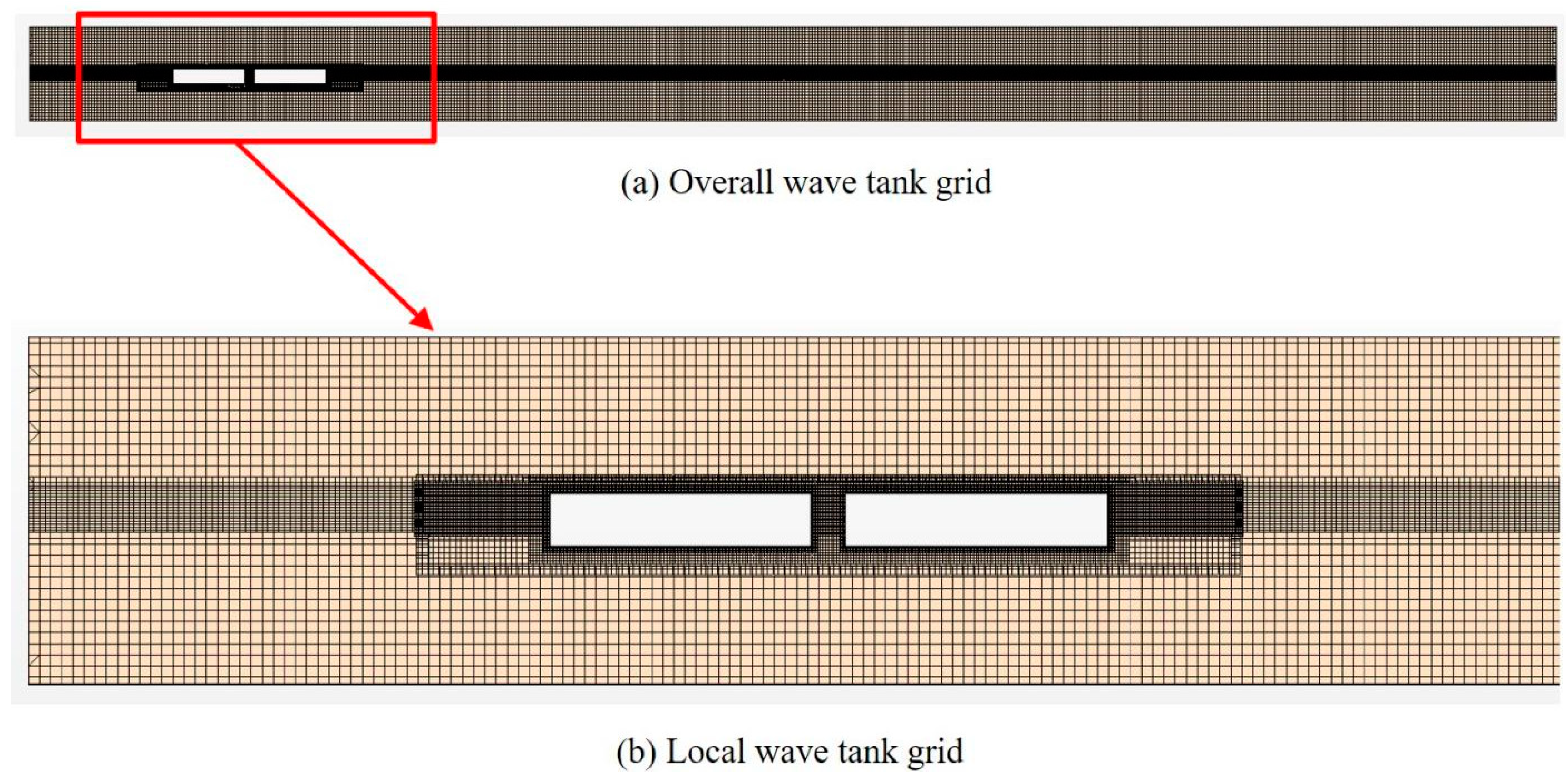
In this study, the generation of numerical freak waves is accomplished using a large CFD platform. The technical flow of the generation of numerical freak waves is shown in Figure 5. A specialized numerical code is created, utilizing Peregrine breather solution theory derived from the nonlinear Schrödinger equation, to produce the theoretical freak wave. Within this framework, CFD is a vital platform that not only generates the freak wave but also conducts the hydrodynamic computation of the ship structure. Moreover, it couples with FEM to execute the hydroelasto-plastic simulation, making CFD an indispensable tool for creating the numerical freak wave. The inlet-velocity wave making method is used to integrate Peregrine breather solution theory with the CFD platform, thereby enabling the generation of the freak wave. Figure 6 illustrates the methodology of creating the freak wave using CFD. Upon solving the nonlinear Schrödinger equation to acquire the Peregrine breather solution theory, the velocity components as described by Equation (3) are attained. Subsequently, a velocity field function for the freak wave is defined at the inlet face of the wave tank within the CFD platform. By implementing the inlet-velocity wave making method, a numerical freak wave can be generated.

4.2. CFD Model

A numerical wave tank, mirroring the physical glass wave tank at the Wuhan University of Technology, has been constructed within the CFD platform. The wave tank model is depicted in Figure 6, which illustrates the hydrodynamic model used in the experiment. Within the CFD platform, a hydrodynamic model has been modeled to closely resemble the hydroelasto-plastic experimental model. Although two floating bodies are meshed, plasticity is not modeled within the CFD platform. The hydrodynamic model serves to calculate wave pressure, which will then be transferred to a structural solver for analyzing motion. Therefore, the Dynamic Fluid Body Interaction (DFBI) method is implemented in the CFD numerical approach. DFBI facilitates the transfer of fluid flux between the free hydrodynamic model meshes and the background grids, employing an overlapping grid method. To optimize this process, the overlapping grids around the ship model are refined, along with a transitional background, to eliminate the challenges associated with interpolating between two grid systems. Additionally, the refinement extends to the background near the free surface, ensuring an accurate representation of surface nonlinearities.
The dimensions of the numerical wave tank are specified with a length of 18 m, a height of 0.8 m, and a water depth of 0.5 m. To minimize the effects of wave reflection, the focusing location of the freak wave is placed as close to the wave maker as possible, situated 1.5 m away. The SST k ω turbulence model is used in the simulation; the selected time scheme is second order and based on a sub-iterative method with a maximum number of sub-iterations of 10. The time step is fixed at 0.005 s with a maximum iteration number of 10. A virtual wave height meter is placed at the focusing location, 1.5 m from the wave maker. This will facilitate a comparison of the wave elevation of the numerical freak wave with both theoretical and experimental results. Numerical wave cases are the same as experimental cases, as given in Table 1. Ref. [27] discussed the convergence of the numerical method by changing mesh size; it was found the CFD model with 2.56 million grids has good computational efficiency and convergence. Therefore, this paper meshes 2.56 million grids for the total fluid domain.

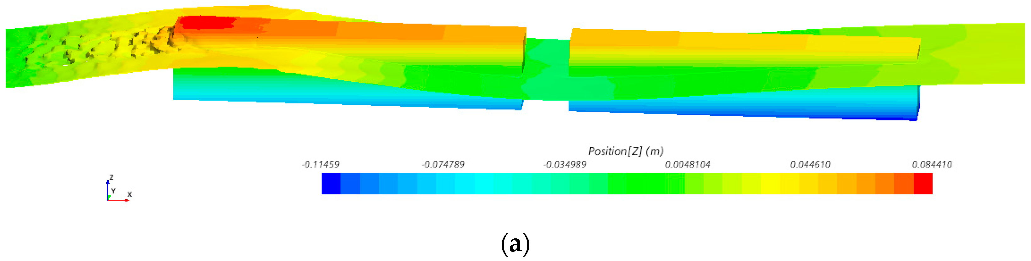
4.3. Numerical Nonlinear FEM Model

A numerical nonlinear FEM model of ship structure, considering both plasticity and structural buckling, is modeled to analyze the structural collapsed response induced by freak waves. This model aligns with the experimental structural design, utilizing two rigid bodies fabricated from fiber-reinforced plastics. Since these bodies exhibit no deformation within the wave tank, they are defined using rigid material properties in the FEM model. The buckling hinge, which connects the two floating bodies, is finely meshed and modeled to generate the collapsed rotation, measurable by two wireless inclinometers. This hinge is designed with a material definition of aluminum and meshed with particularly refined elements to simulate the collapse response. The overall nonlinear FEM model consists of 9752 elements, with a maximum element size of 0.01 m for the floating body and 0.001 m for the buckling hinge. The element size of the wet surface of the floating bodies in the FEM model closely matches the grid size of the hydrodynamic model, enabling effective interpolation of wave pressures and displacement. Figure 7 illustrates the nonlinear FEM model. Although the two-way FSI scheme is used in this study, only pitch and heave motions are allowable, with other Degrees of Freedom (DOFs) constrained to eliminate irrelevant displacement, as depicted by the constraints shown in Figure 7.
The buckling hinge serves as a critical structural component for measuring the structural collapsed rotation. In order to analyze its collapse capacity, the nonlinear FEM model of the buckling hinge is selected. This facilitates the calculation of its ultimate strength and large rotational deformation, and a curve relating bending moment to rotation angle is derived. Liu et al. [25,28] used the same buckling hinge to provide insights into its numerical characteristics. They employed nonlinear FEM to determine the ultimate bending moment as well as to plot the curve of Bending Moment (BM) against rotation, as depicted in Figure 8. It is observed from Figure 9 that the sagging ultimate bending moment is larger than the hogging ultimate strength because the upper plate of the buckling hinge is weaker than the lower plate of the buckling hinge. This indicates that the buckling can be deduced and the ultimate strength increased if the deck structure of the ship is reinforced. It is seen from Figure 8 that the maximum bending moment appears when the rotation angle exceeds the collapsed rotation angle, which is equal to 0.121°, and then the bending moment declines. It means the angle of 0.121° is critical buckling deformation, after which buckling deformation is generated irretrievably. Ultimate sagging Bending Moment (BM) and ultimate hogging BM and their critical rotational angles are given in Table 2.
The collapsed mode of the hinge is characterized by buckling instability at the upper or lower edge when bent, a phenomenon clearly illustrated in Figure 9. It is obvious that the buckling is generated in the upper plate of the buckling hinge. It is found that nonlinear FEM simulation and experiment have similar collapsed modes of buckling hinge.

5. Results Analysis

Hydroelasto-plastic experiments are carried out to study the structural collapse and rotational deformation of an experimental model under freak waves. A two-way FSI numerical hydroelasto-plastic approach, coupling CFD for generating numerical freak waves and nonlinear FEM, is used to calculate time-domain rotation histories.

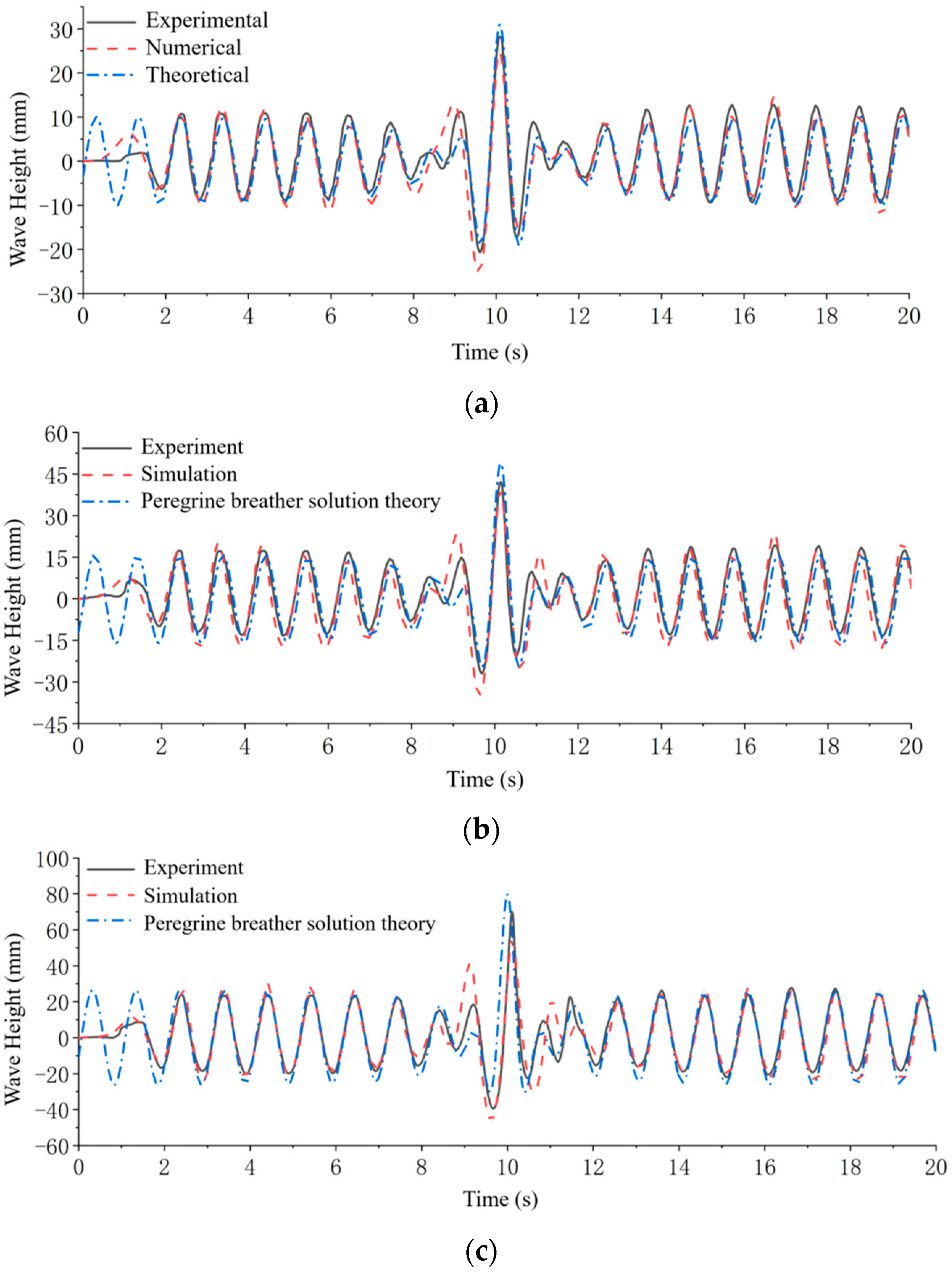
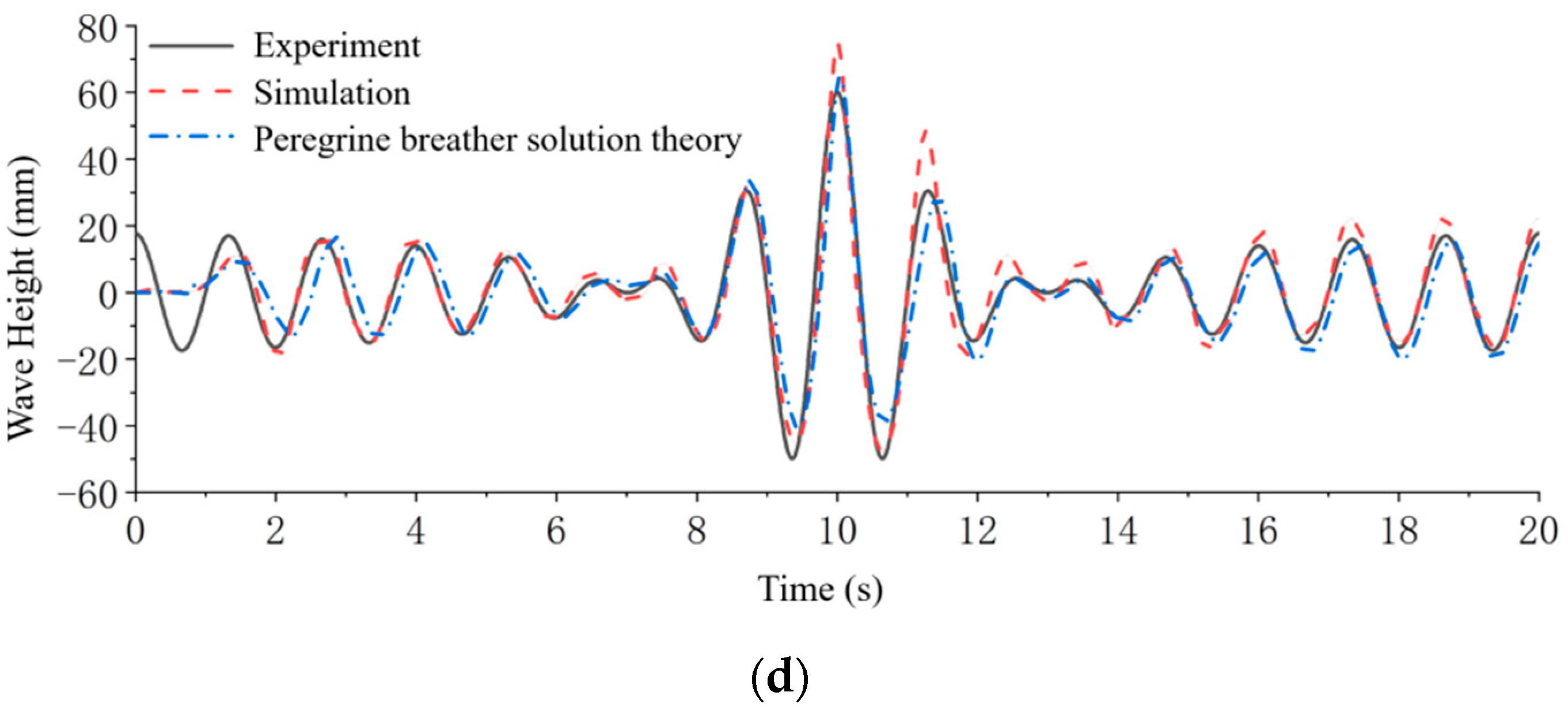
5.1. Wave Elevation Analysis

Experimental freak waves, which are a precondition for conducting a hydroelasto-plastic model experiment, need to be verified for effectiveness. Experimental, numerical, and theoretical wave elevations of the freak wave are compared and analyzed. The experimental wave elevation history is measured by a wave height gauge in the wave tank; the numerical history is calculated by CFD through Section 4.1 and Figure 5, and all wave cases are given in Table 1. This study analyzes wave elevation histories for Case H1 (wave height of 0.05 m and wavelength of 1.6 m), Case H2 (wave height of 0.07 m and wavelength of 1.6 m), Case H4 (wave height of 0.11 m and wavelength of 1.6 m), and Case L2 (wave height of 0.11 m and wavelength of 2.4 m).
Figure 10a presents wave elevation histories of Case H1 obtained from experimental, numerical, and theoretical means. There is a large freak wave appearing in a regular wave train, and the three histories share similar waveforms. Figure 10b reveals wave elevation histories of Case H2, showing similar wave characteristics compared to Case H1. Figure 10c displays wave elevation histories of Case H4, which will cause the structural collapsed response of the experimental model. The three histories have slight differences in the crest of the freak wave. Figure 10d illustrates Case L2, which changes the wavelength from a model length of 1.6 m to 2.4 m. The three histories align closely with each other.
According to the results of freak wave elevation in this study, the three methodologies of experiment, simulation, and theory of nonlinear Schrödinger equation almost have similar freak wave forms and wave heights; it is indicated that these methodologies for creating freak waves are feasible and dependable. Particularly, the numerical freak waves obtained by the method of combining CFD with the inlet-velocity wave making method and Peregrine breather solution theory are proven to be effective. They can be used to study the hydroelasto-plastic response of the ship structure.
Figure 11 illustrates the focusing waveforms of both numerical and experimental freak waves for Case H1. It is evident from Figure 11 that there is a large peak in the focusing wave crest. The similarity between the simulated and experimental freak waves, especially in form, establishes a firm foundation for subsequent hydroelasto-plastic model experiments of ship structure under freak wave conditions.

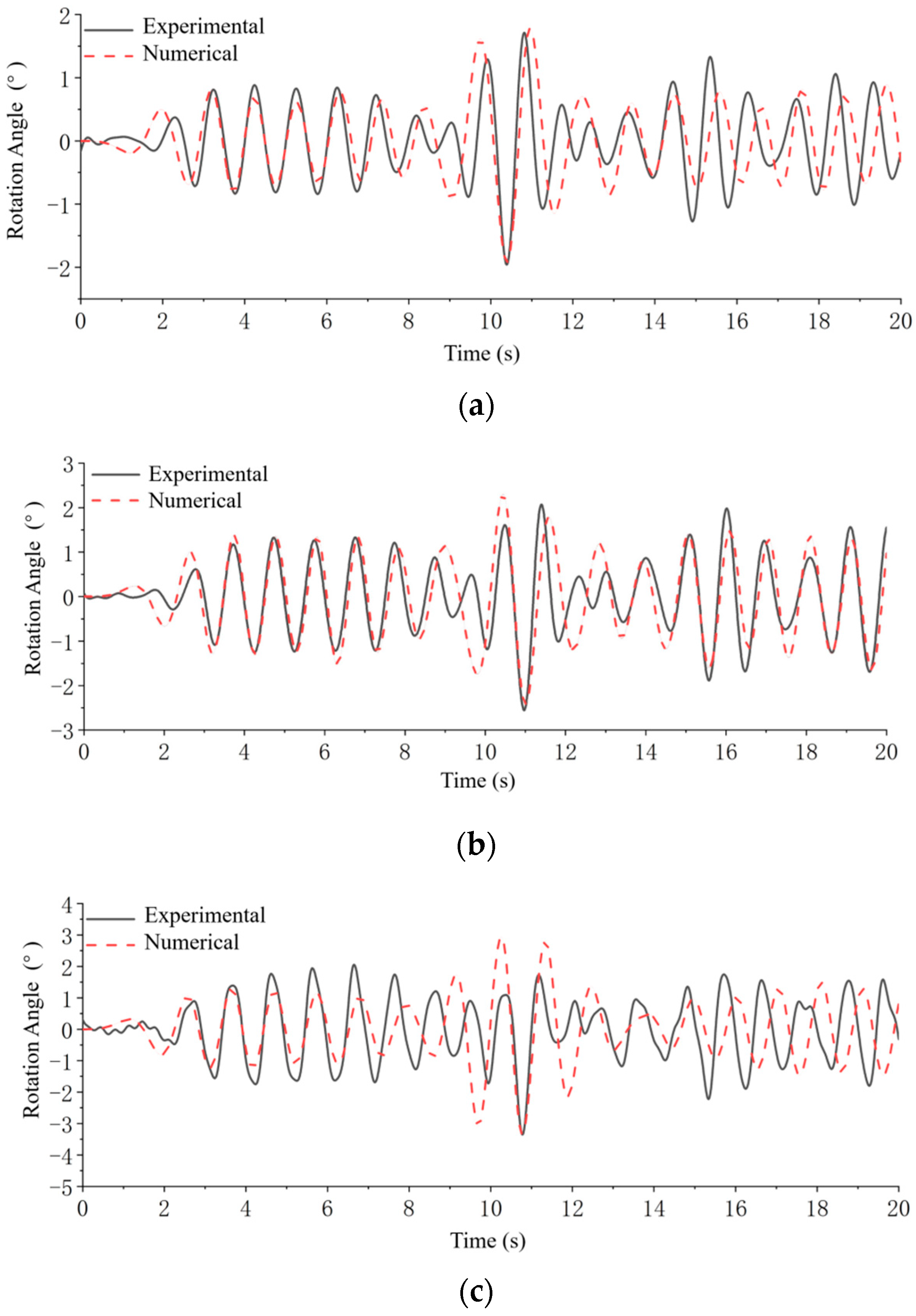
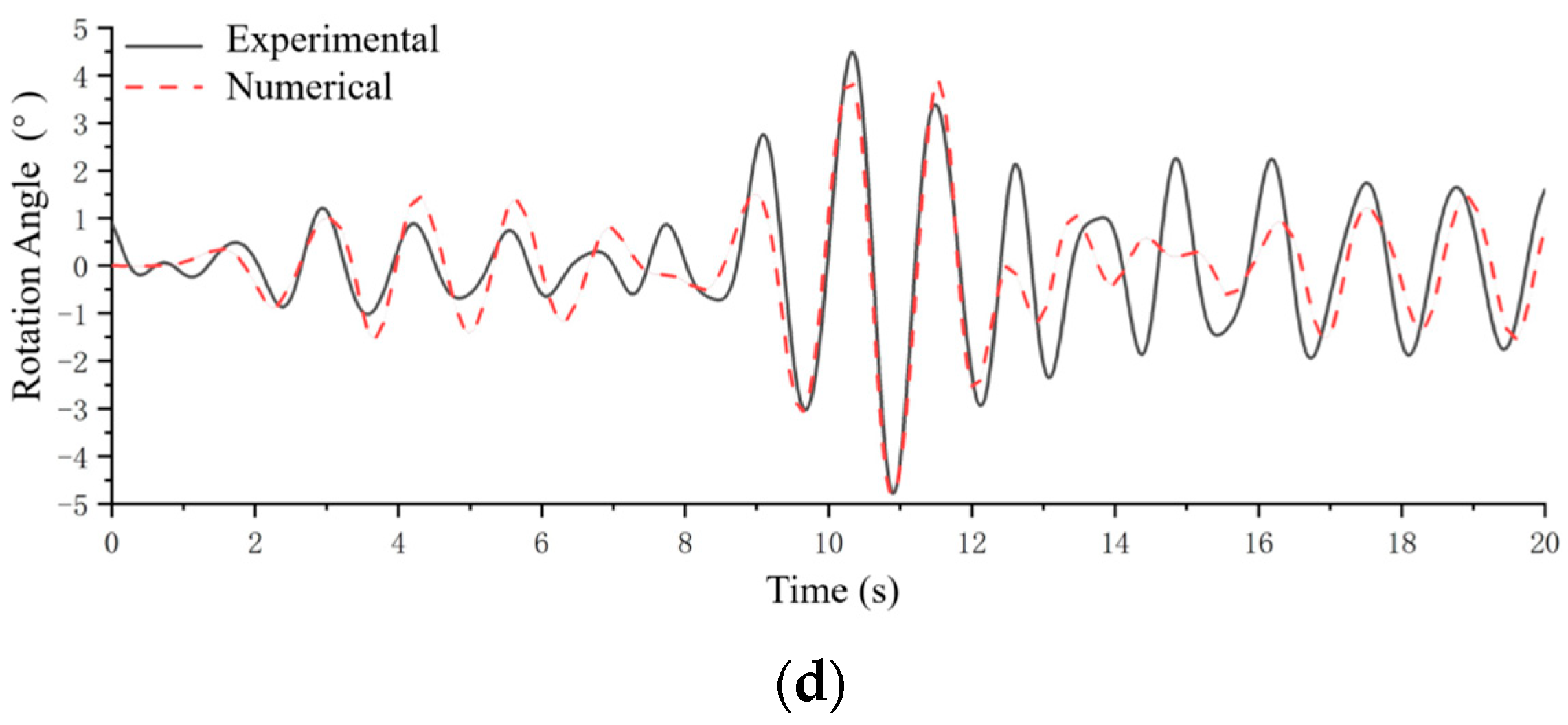
5.2. Rotational Deformation Analysis

A hydroelasto-plastic experimental model, comprised of two floating bodies and a connectable buckling hinge, has been designed and manufactured. The buckling hinge is employed to induce damage and produce collapsed large rotational deformation, which is the central focus of this study. The hydroelasto-plastic model is placed to tank freak waves, resulting in substantial structural rotation. This rotation is measured by the difference in readings from two wireless inclinometers, arranged in the middle cabins of each floating body, as shown in Figure 2b. Experimental rotation histories are obtained from these measurements. Additionally, a numerical methodology that integrates both the CFD solver and a theoretical code-generating freak wave is proposed to generate numerical freak waves for following hydroelasto-plastic simulations of the ship structure. Another numerical FSI approach, coupling CFD with nonlinear FEM, calculates the hydroelasto-plastic rotation histories, considering structural plasticity and buckling instability. The comparison between experimental and numerical rotations provides insights into their precision.
All cases detailed in Table 1 are examined in the hydroelasto-plastic experiment, with this study focusing on the analysis of rotation histories for Cases H1, H2, H4, and L2, as shown in Figure 12. Positive value represents hogging rotation, while negative values signify sagging rotation. It is very obvious that the time-domain histories of Figure 13 are very similar to the histories of Figure 11. Figure 11 is the wave elevations of freak waves; Figure 12 is the rotational deformation of the ship model in freak waves; and the freak wave is input to solve the structural response of the experimental model. That is why they have a certain degree of similarity. Figure 12a provides the experimental and numerical rotation for Case H1, highlighting a large rotation trough indicative of significant sagging bending deformation due to the buckling hinge’s weak sagging loading capacity. Figure 12b,c show similar deformation characteristics for Cases H2 and H4, respectively, and Figure 12c presents the results for Case L2. For Cases H1, H2, and H4, the wavelength remain consistent at 1.6 m, while the wave height varies between 0.05 m and 0.11 m. Case L2 differs by extending the wavelength to 2.4 m while maintaining the wave height consistent with Case H4. A close alignment between experimental and numerical rotation histories is observable in Figure 12 with maximum rotation angles exceeding the rotation of the ultimate bending moment shown in Figure 6. It is seen from Figure 12 that the collapsed deformations are generated in Cases H1, H2, H3, H4, and L2, with the maximum rotational angles shown in Figure 12 which are much larger than the collapsed angle of the buckling hinge 0.121 as shown in Figure 8, it indicates that collapsed response of the buckling hinge is generated.
These observations demonstrate the efficacy of the numerical hydroelasto-plastic approach in simulating the collapse response of the ship structure under freak waves. It also confirms that Cases H1, H2, H4, and L2 successfully induced collapsed rotational deformations, creating the desired hydroelasto-plastic response in the ship structure for this experiment. Case H4, as a representative example of a freak wave case that generates a large collapsed rotation, merits further investigation into its deformation mode and pressure distribution. A large deformational moment when the experimental model is deformed at the largest sagging deformation, as Figure 12c shows, has been selected for an in-depth analysis of this phenomenon.
Figure 13 provides images of the hydroelasto-plastic model, including FEM cloud charts, pressure nephograms, and experimental images captured at moment T1. Figure 13a shows the wave pressure distribution along with the free surface of the freak wave. Figure 13b provides the stress cloud chart of the nonlinear FEM model, revealing substantial sagging rotational deformation and buckling, and unstable deformation within the hinge. Figure 13c presents real images from the hydroelasto-plastic experiment. The close agreement between the deformational mode and distribution of the motion-free surface in the numerical investigation and the experimental results indicates that the numerical approach is acceptable for simulating the hydroelasto-plastic problem.

6. Discussion

The research results of all cases have been examined to elucidate the mechanisms underlying the structural collapses of the hydroelasto-plastic model, with particular attention paid to variations in wave height and wavelength. Cases H1–H4 maintain a consistent wavelength equal to the model length of 1.6 m while changing the wave height from 0.05 m to 0.11 m. The maximum rotational deformation has been statistically analyzed. Figure 14a shows the rotational deformation as a function of wave height, revealing an increase in maximum rotation corresponding to rising wave height. The alignment between numerical and experimental outcomes is notably close in these observations. The examination is further extended to other wave cases, where wavelengths are varied from 0.8 m to 4.8 m. It is seen from Figure 14a that an almost linear rise is generated; it is analyzed that the range of wave heights is too small for experimental cases; the range of wave height is just from 0.05 m to 0.11 m. A larger and more nonlinear response of the buckling hinge cannot be revealed in Figure 14a. Figure 14b presents the maximum rotational deformation with respect to changing wavelength. A distinct peak value is observed at a length ratio of 2.0 when altering wavelength. The close correspondence between simulation and experiment across these cases underscores the validity of the numerical approach proposed in this paper for studying the hydroelasto-plastic problems.

7. Conclusions

This paper studies the hydroelasto-plastic responses of a ship structure subjected to freak waves through both model experiments and numerical investigations. An experimental method for generating freak waves is proposed using the nonlinear Schrödinger equation, and a numerical approach is developed that combines CFD and Peregrine breather solution theory. Hydroelasto-plastic model experiments are carried out in tank freak waves, and a numerical approach coupling CFD and nonlinear FEM is performed to simulate these experiments. A detailed comparison and analysis of the numerical and experimental results are undertaken, leading to 4 key conclusions:
(1)
Peregrine breather solution theory, derived from the NLS equation, offers a nonlinear and stable means for generating both numerical and experimental freak waves.
(2)
The hydroelasto-plastic model experiment of ship structure under tank freak waves is realized using a relative strength model design. The appropriate selection of a buckling hinge and the application of tank freak wave obtained from the Peregrine breather solution theory is pivotal to this process.
(3)
This paper introduces a numerical hydroelasto-plastic framework that integrates Peregrine breather solution theory with an FSI approach, utilizing CFD and nonlinear FEM. This method is validated against experimental data, yielding strong agreements between the numerical and experimental results. A key observation is a large sagging rotational deformation, reaching a maximum value of 4.6 degrees (substantially greater than elastic rotation), indicating actual structural collapse in this study. Both numerical and experimental approaches successfully capture this significant collapsed rotation.
(4)
Computational time and meshing techniques are important challenges to carrying out hydroelasto-plastic response calculation for ocean structure. The numerical approach used in this paper involves solutions of CFD and nonlinear FEM; it needs to take a large amount of time and cost. Moreover, meshing qualities of CFD and FEM are still important to realize FSI numerical investigation, grid sizes of the CFD model and element sizes of FEM meshes need to be kept close.
(5)
The numerical and experimental results demonstrate that the maximum angular deformation of the midship increases with wave height. When the wave-length to model-length ratio is less than 2, the maximum midship rotation angle rises with this ratio. The peak angular deformation occurs when the wavelength is approximately twice the length of the structure. Beyond a wavelength/structural length ratio of 2, the maximum angular deformation decreases with an increase in this ratio.
(6)
While the numerical hydroelasto-plastic approach has proven effective in simulating the hydroelasto-plastic model experiment, future work may extend this methodology to explore the collapsed structural response of real ship structures under oceanic freak waves.

Author Contributions

Conceptualization, W.L.; Methodology, and Validation, L.X.; Formal analysis, Y.M.; Investigation, X.S.; Writing—review & editing, H.X. and Y.L. All authors have read and agreed to the published version of the manuscript.

Funding

This research was funded by the National Key Research and Development Project (2022YFC3006001), Wuhan Science and Technology Plan Project (2023010402010602), National Natural Science Foundation of China (No. 52071243 and 52101371), and the development and application project of ship CAE software.

Data Availability Statement

The raw data supporting the conclusions of this article will be made available by the authors on request.

Conflicts of Interest

The authors declare no conflict of interest with any individuals and entities.

References

  1. Haver, S.; Vestbostad, T.M.; Andersen, O.J.; Jakobsen, J.B. Freak waves and their conditional probability problem. In Proceedings of the Fourteenth International Ship and Polar Engineering Conference, Toulon, France, 23–28 May 2004. [Google Scholar]
  2. Haver, S. Freak Waves; Ifremer: Brest, France, 2001; pp. 129–140. [Google Scholar]
  3. Haver, S. Freak Wave Event at Draupner Jacket January 1 1995; Statoil Technical: Stavanger, Norway, 2003. [Google Scholar]
  4. Gunson, J.; Lehner, S.; Bitner-Gregersen, E. Extreme Wave Conditions from Wave Model Hindcasts and from Synthetic Aperture Radar Images. In Proceedings of the International Conference on Design and Operation for Abnormal Conditions II, London, UK, 6–7 November 2001. [Google Scholar]
  5. Müller, P.; Garrett, C.; Osborne, A. Freak waves. Oceanography 2005, 18, 66. [Google Scholar] [CrossRef]
  6. Anders, M. Update on incident involving the containership MOL Confort. Am. J. Transp. 2013, 558, 19. [Google Scholar]
  7. Vikram, M. Ukrainian Cargo Ship Arvin Sinks off Black Sea. Available online: https://maritime.direct/en/2021/01/18/ukrainian-cargo-ship-arvin-sinks-off-black-sea/ (accessed on 18 January 2021).
  8. Kriebel, D.L.; Alsina, M.V. Simulation of freak waves in a background random sea. In Proceedings of the Tenth International Ship and Polar Engineering Conference, Seattle, WA, USA, 27 May–2 June 2000. [Google Scholar]
  9. Kim, N.; Kim, C.H. Investigation of a dynamic property of Draupner freak wave. Int. J. Ship Polar Eng. 2003, 13, 1–12. [Google Scholar]
  10. Sheng, Y. Numerical Simulation of Freak Wave and the Interactions Between Freak Wave and Ship Structure. Master’s Thesis, Shanghai Jiaotong University, Shanghai, China, 2013. [Google Scholar]
  11. Waseda, T.; Rheem, C.K.; Sawamura, J.; Yuhara, T.; Kinoshita, T.; Tanizawa, K.; Tomita, H. Freak wave generation in Laboratory Wave Tank. In Proceedings of the 15th International Ship and Polar Engineering Conference, Seoul, Republic of Korea, 19–24 June 2005. [Google Scholar]
  12. Hu, Z.; Tang, W.; Xue, H.; Zhang, X. Numerical study of Freak waves as nonlinear Schrödinger breather solutions under finite water depth. Wave Motion 2015, 52, 81–90. [Google Scholar] [CrossRef]
  13. Chabchoub, A.; Hoffmann, N.; Akhmediev, N. Freak wave observation in a water wave tank. Phys. Rev. Lett. 2011, 106, 204502. [Google Scholar] [CrossRef] [PubMed]
  14. Zakharov, V.E.; Dyachenko, A.I.; Prokofiev, A.O. Freak waves as nonlinear stage of Stokes wave modulation instability. Eur. J. Mech. B Fluids 2006, 25, 677–692. [Google Scholar] [CrossRef]
  15. Didenkulova, I.I.; Nikolkina, I.F.; Pelinovsky, E.N. Freak waves in the basin of intermediate depth and the possibility of their formation due to the modulational instability. JETP Lett. 2013, 97, 194–198. [Google Scholar] [CrossRef]
  16. Clauss, G.F.; Kauffeldt, A.; Klein, M. Systematic investigation of loads and motions of a bulk carrier in extreme seas. In Proceedings of the 28th International Conference on Ship Mechanics and Arctic Engineering, Honolulu, HI, USA, 31 May–5 June 2009; Volume 43444, pp. 277–287. [Google Scholar]
  17. Shi, J.S.; Takuji, W.; Katsuyuki, S.; Takeshi, K.; Tetsuo, Y. Wave Loads on Container Ship in Freak Waves; The Japan Society of Naval Architects and Ocean Engineers: Tokyo, Japan, 2006. [Google Scholar]
  18. Kinoshita, T. Longitudinal Loads on a Container Ship in Extreme Regular Sea and Freak Wave. In Proceedings of the 4th International Conference on Hydroelasticity in Marine Technology, Wuxi, China, 10–14 September 2006. [Google Scholar]
  19. Holst, A.; Gunnar, D.; Celine, F. CFD Analysis of Wave-Induced Loads on Tidal Turbine Blades. IEEE J. Ocean. Eng. 2015, 40, 506–521. [Google Scholar] [CrossRef]
  20. Wang, J.; Hao, Q.; Zhe, H.; Lin, M. Three-dimensional study on the interaction between a container ship and freak waves in beam sea. Int. J. Nav. Archit. Ocean. Eng. 2022, 15, 100509. [Google Scholar] [CrossRef]
  21. Liu, Y. Hydroelastic Response of Large Floating Structure in Nonlinear Waves. Master’s Thesis, Jiangsu University of Technology, Zhenjiang, China, 2020. [Google Scholar]
  22. Masaoka, K.; Okada, H. A numerical approach for ship hull girder collapse behavior in waves. In Proceedings of the Thirteenth International Ship and Polar Engineering Conference, Honolulu, HI, USA, 25–30 May 2003. [Google Scholar]
  23. Iijima, K.; Kimura, K.; Xu, W.; Fujikubo, M. Hydroelasto-plasticity approach to predicting the post- ultimate strength behavior of a ship’s hull girder in waves. J. Mar. Sci. Technol. 2011, 16, 379–389. [Google Scholar] [CrossRef]
  24. Lee, S.; You, J.; Lee, H.; Lim, T.; Park, S.; Seo, J.; Rhee, S.; Rhee, K. Experimental Study on the Six Degree-of-Freedom Motions of a Damaged Ship Floating in Regular Waves. IEEE J. Ocean. Eng. 2016, 41, 40–49. [Google Scholar]
  25. Liu, W.; Song, X.; Wu, W.; Suzuki, K. Strength of a Container Ship in Freak waves Obtained by Nonlinear Hydroelasto-plasticity Dynamic Analysis and Finite Element Modeling. J. Ship Mech. Arct. Eng. 2016, 138, 031602. [Google Scholar]
  26. Liu, W.; Huang, Y.; Li, Y.; Song, X.; Wei, F.; Wu, X. Numerical and experimental investigation on nonlinear cyclic collapse response of ship model in regular waves. J. Ship Mech. Arct. Eng. 2021, 143, 041702. [Google Scholar] [CrossRef]
  27. Liu, W.; Luo, W.; Yang, M.; Xia, T.; Huang, Y.; Wang, S.; Li, Y. Development of a fully coupled numerical hydroelasto-plastic approach for ship structure. Ocean Eng. 2022, 258, 111713. [Google Scholar] [CrossRef]
  28. Liu, W.; Song, X.; Pei, Z.; Li, Y. A Hydroelasto-buckling Experiment Study of Ship Model in Single Wave. Ocean Eng. 2017, 142, 102–114. [Google Scholar] [CrossRef]
  29. Mei, C.C. The Applied Dynamics of Ocean Surface Waves; World Scientific: Singapore, 1989; Volume 1. [Google Scholar]
Figure 1. Research flow of this paper.
Jmse 12 01555 g001
Figure 2. Hydroelasto-plastic ship model and arrangement of test instruments; (a) Hydroelasto-plastic ship model; (b) Cutaway view of the arrangement of test instruments.
Jmse 12 01555 g002
Figure 3. Experimental schematic diagrams of model arrangement in the wave tank.
Jmse 12 01555 g003
Figure 4. Data exchange diagram of fluid-solid bidirectional coupling in iteration time step.
Jmse 12 01555 g004
Figure 5. Methodology of making freak wave in CFD platform.
Jmse 12 01555 g005
Figure 6. Modeling and grids of wave tank and ship body.
Jmse 12 01555 g006
Figure 7. Nonlinear FEM model of hydroelasto-plastic experimental model.
Jmse 12 01555 g007
Figure 8. Curve of bending moment and rotation of buckling hinge.
Jmse 12 01555 g008
Figure 9. Collapsed modes of buckling hinge.
Jmse 12 01555 g009
Figure 10. Freak wave elevation histories of cases of H1, H2, H4, and L2; (a) Freak wave elevation histories of Case H1; (b) Freak wave elevation histories of Case H2; (c) Freak wave elevation histories of Case H4; (d) Freak wave elevation histories of Case L2.
Jmse 12 01555 g010aJmse 12 01555 g010b
Figure 11. Wave elevation of a freak wave of Case H1.
Jmse 12 01555 g011
Figure 12. Numerical and experimental rotation histories of Case H1, H2, H4, and L2; (a) Numerical and experimental rotation histories of Case H1; (b) Numerical and experimental rotation histories of Case H2; (c) Numerical and experimental rotation histories of Case H4; and (d) Numerical and experimental rotation histories of Case L2.
Jmse 12 01555 g012aJmse 12 01555 g012b
Figure 13. Comparison of the hydroelasto-plastic model at the largest deformational moment for Case H4; (a) Wave pressure nephogram of the hydrodynamic model; (b) Stress cloud chart of nonlinear FEM model; (c) Real image of the hydroelasto-plastic experiment.
Jmse 12 01555 g013aJmse 12 01555 g013b
Figure 14. Rotational deformation by changing wave height and wavelength; (a) Rotational deformation by changing wave height; (b) Rotational deformation by changing wavelength.
Jmse 12 01555 g014
Table 1. Wave parameters of cases.
CaseWave Height (m)Wavelength/Model LengthWavelength (m)Period (s)
H10.0511.61.0123
H20.0711.61.0123
H30.0911.61.0123
H40.1111.61.0123
L20.111.52.41.2398
L30.1123.21.4316
L40.1134.81.7534
Table 2. Ultimate BMs and critical rotational angles of buckling hinge.
Ultimate Sagging BM (N·mm)Critical Rotational Angle (°)Ultimate Hogging BM
(N·mm)
Critical Rotational Angle (°)
Experiment18500.121−10269−0.3048
Simulation17920.101−10631−0.3811
Disclaimer/Publisher’s Note: The statements, opinions and data contained in all publications are solely those of the individual author(s) and contributor(s) and not of MDPI and/or the editor(s). MDPI and/or the editor(s) disclaim responsibility for any injury to people or property resulting from any ideas, methods, instructions or products referred to in the content.

