Article

A Study on the Bearing Capacity of Square Skirted Anchors with Different Mooring Points

1
School of Civil Engineering, Tianjin University, Tianjin 300072, China
2
State Key Laboratory of Hydraulic Engineering Intelligent Construction and Operation, Tianjin University, Tianjin 300350, China
*
Author to whom correspondence should be addressed.
J. Mar. Sci. Eng. 2024, 12(9), 1572; https://doi.org/10.3390/jmse12091572
Submission received: 2 August 2024 / Revised: 31 August 2024 / Accepted: 1 September 2024 / Published: 6 September 2024
(This article belongs to the Section Ocean Engineering)

Abstract

:
Skirted anchors are often used as temporary or permanent anchoring foundations for underwater pipelines and floating platforms. A series of model tests and finite element simulations were conducted to study the bearing capacity of square skirted anchors with different mooring points. Based on the test results, two failure modes of square skirted anchors with different mooring points were analyzed. It was found that, when the mooring point was located at the top of the side skirt, the square skirted anchor was more prone to rotation and had a lower bearing capacity. The numerical method was validated by the model tests. In total, 140 numerical calculation results show that, when the mooring point position (normalized depth of mooring point) h/H = 0.5~0.75 and the load inclination angle θ = 0°~30°, the bearing performance of the square skirted anchor is optimal. As the aspect ratio of the square skirted anchor (H/B) increases from 0.25 to 2.0, the optimal mooring point position h/H moves downward from 0.5 to 0.75. The failure envelopes in the V-H loading space of the square skirted anchor were drawn, and the corresponding fitting equation was obtained.

1. Introduction

In recent years, skirt-type anchors (or foundations) have been widely used for the temporary or semipermanent anchoring of underwater pipelines or cables, semisubmersible platforms, and other marine structures. Common skirt-type anchors include skirted mudmats [1,2], suction caissons [3,4,5,6,7,8,9,10], and hybrid skirted foundations [11]. The square skirted anchor composed of a thin steel top plate, four steel side skirts, and necessary internal support has the advantages of simple structure and high applicability compared to other skirt-type anchors and is currently widely used in marine engineering.
There is abundant research on the bearing capacity of skirt-type anchors. The indoor model test and centrifuge model test can directly determine the bearing capacity of skirt-type anchors, intuitively revealing the displacement of the anchor and the response of the surrounding soil. However, due to limitations, such as the cost and time of physical tests, it is generally difficult to obtain complete failure response data for prototype anchors [12,13,14,15,16]. Theoretical research on the bearing capacity of skirted anchors includes the limit equilibrium method, limit analysis method, etc. [17,18,19,20,21]. The limit equilibrium method [21] is based on the analysis of soil pressure to establish the equilibrium equation of the force or moment of the anchor to determine the bearing capacity. This method has the advantages of a simple model, convenient formula, and easy understanding but cannot be used in heterogeneous soil. The limit analysis method obtains the upper and lower limits of the bearing capacity by solving the velocity field and stress field and can be used in nonuniform soil [19,22,23].
The numerical analysis method is one of the main approaches for studying the bearing capacity of skirt-type anchors [24,25,26]. Numerous scholars have studied the influence of various factors on the bearing capacity of skirted anchors, including the anchor shape and burial depth [27,28,29], geological distribution conditions [11,30], soil properties [6,25,31], combined load action modes [32,33], installation effects [34], and structure–soil interactions [33,35]. However, existing research has mostly focused on suction bucket foundations or shallow foundations such as mudmats. Further systematic study is needed on the failure mechanism and bearing capacity of the square skirted anchor with a wider range of applications, providing reference for the design of square skirted anchors in different application scenarios.
In this article, a series of model tests and three-dimensional finite element simulations were conducted to study the bearing capacity and displacement mechanisms of square skirted anchors with different mooring points. The inclined bearing capacity of prototype square skirted anchors with different aspect ratios and mooring points in saturated clay were studied by the finite element method. The influences of the aspect ratio of the skirted anchor, the position of the mooring point, and the load inclination angle on the bearing characteristics of the square skirted anchor were studied. A total of 140 bearing conditions for square skirted anchors were calculated.

2. Model Tests

2.1. Model Test Setup

The model tests were conducted in a test tank with a length, width, and height of 1 m, as shown in Figure 1. Sand, soft clay, and water were placed in the test tank from bottom to top in sequence. The thickness of the bottom sand layer was 30 cm. The thickness of the top water layer was 10 cm. The test tank was placed under a door-shaped loading reaction frame with a height of 2 m and a width of 2 m. A loading motor with a controllable loading speed and a loading rod with a lifting ring at the bottom that could be retracted up and down by 200 mm was installed on the door-type loading reaction frame. A force sensor with a BLR-1 model (Huadong Electronic Instrument Factory, Shanghai, China) and a range and sensitivity of 100 kg and 0.05% FS was connected between the motor and the loading rod. The loading control box shown in Figure 1b could control the loading motor to drive the loading rod to load uniformly upward or downward. A horizontal beam made of two square steel bars was installed at the top of the test tank, and a steel vertical beam that extended downward into the test tank was installed on the horizontal beam. A fixed pulley was installed on the vertical beam. A wire rope was used to connect the mooring point of the square skirted anchor model, and the other end of the steel wire rope was connected to the lifting ring of the loading rod by bypassing the pulley. The load applied to the square skirted anchor model in the tests was provided by the loading motor and loading rod and transmitted by the wire rope.
A linear variable displacement transducer (LVDT) was fixed together with the force sensor to test the displacement of the loading rod, i.e., the distance at which the skirted anchor model was pulled during the tests. The LVDT model was 5G107 (Donghua Testing Technology Co., Ltd., Taizhou, China), with a range and sensitivity of 200 mm and 0.05% FS, respectively. An inclinometer with a sensitivity of 0.1° was installed on the top plate of the skirted anchor model to measure its rotation angle. All these sensors, such as force sensor, LVDT, and inclinometer, were connected to a DH3820 data acquisition instrument (Donghua Testing Technology Co., Ltd., Taizhou, China) and a computer. During the loading process of the test, the displacement, rotation angle, and pulling force of the skirted anchor model were measured and recorded in real time.

2.2. Skirted Anchor Model

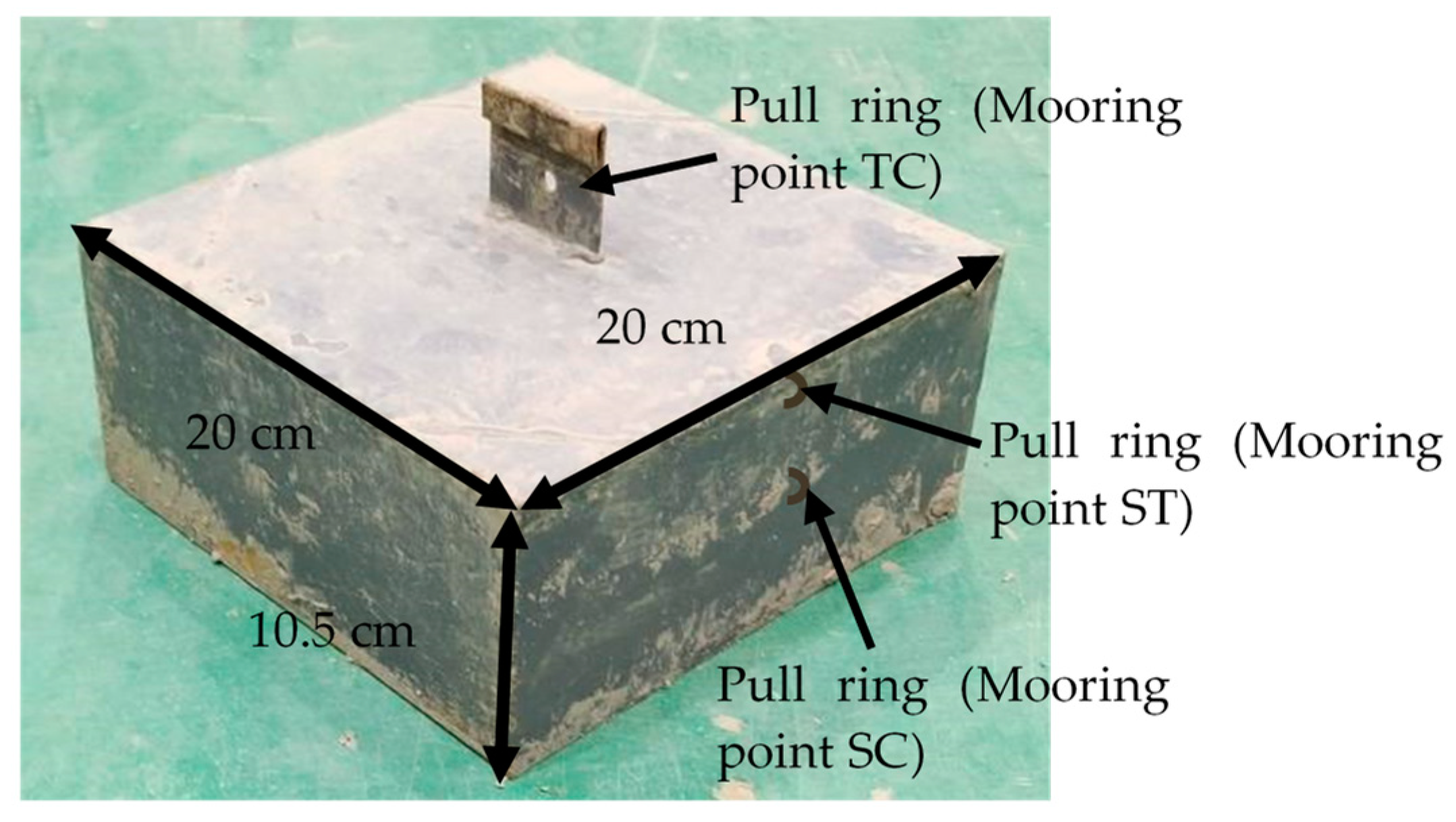
A skirted anchor model was made by welding steel plates, as shown in Figure 2. It consists of four skirt plates and one top plate, with a length, width, and height of 20 cm, 20 cm, and 10 cm, respectively. The top plate has a thickness of 5 mm, and the side skirt plate has a thickness of 2 mm. Both the inner and outer surfaces were coated with anti-rust paint. The geometric scale ratio of this skirted anchor model is 1:30 compared to the prototype skirted anchors with lengths, widths, and heights of 6 m, 6 m, and 3 m, respectively. Pull rings were installed at the center of the top plate (TC), the top endpoint (ST) of the side skirt, and the center point (SC) of the side skirt. The pull ring at the TC point was used to recycle the skirted anchor after the model tests. The pull rings at the ST and SC points were used in the model tests to connect the steel wire rope that transmits the pulling load.

2.3. Soil Parameters

The clay used in the model tests was taken from the coastal area of Tianjin, with a specific gravity of 2.67, a plastic limit of 38%, a liquid limit of 61%, and a plasticity index of 23. According to the soil classification system of the USCS, it can be classified as low-plasticity clay (CL).
The preparation process of the soil samples was as follows: the bottom of the test tank was first laid with a drainage sand layer, which was covered with a layer of geotextile. The clay sample underwent drying, grinding, water addition at a water content of 65%, and stirring to form a fully saturated slurry. The prepared slurry was slowly poured into the test tank until the top of the slurry surface was approximately 5 cm away from the top of the test tank. After the slurry was left to stand in the test tank for 2 days, a layer of geotextile and a 1 cm thick wooden plate were placed on the slurry surface. Load blocks were evenly placed on the wooden board to compress and consolidate the soil, with a total pressure of approximately 2 kPa. After 15 days of compaction, the load blocks, wooden plate, and geotextile were removed. Vane shear strength tests were conducted to measure the undrained shear strength su of the clay sample. The measured undrained strength of the clay is shown in Figure 3. After taking the average of the results of the vane shear test, the distribution curve of the undrained strength of the soil sample su with depth was obtained, as shown in Figure 3. The strength of the clay sample su is approximately 1.2 kPa at the soil surface and approximately 1.3 kPa at a depth of 30 cm.
Using the GDS stress path triaxial apparatus, indoor triaxial shear tests, such as consolidated undrained and rebound tests, were conducted, and the parameters of the soil were obtained, as shown in Table 1.

2.4. Test Procedures

The test procedures were as follows:
  • The skirted anchor was slowly and uniformly pressed into the clay, as shown in Figure 1b, using a loading motor and a loading rod until the top plate of the skirted anchor model was aligned with the surface of the clay layer.
  • The pull rings on the top point ST and middle point SC of the side skirt of the square skirted anchor were selected and connected to the steel wire rope.
  • The loading control system was turned on with a loading rate set as 2 mm/min, and the steel wire rope was tightened.
  • The data acquisition device was turned on, and all sensors were reset to zero.
  • The loading motor was started to apply horizontal or inclined loads to the square skirted anchor. The test was stopped when the measured force significantly decreased or no longer changed. The displacement and force applied to the square skirted anchor were recorded during the test.

2.5. Test Results

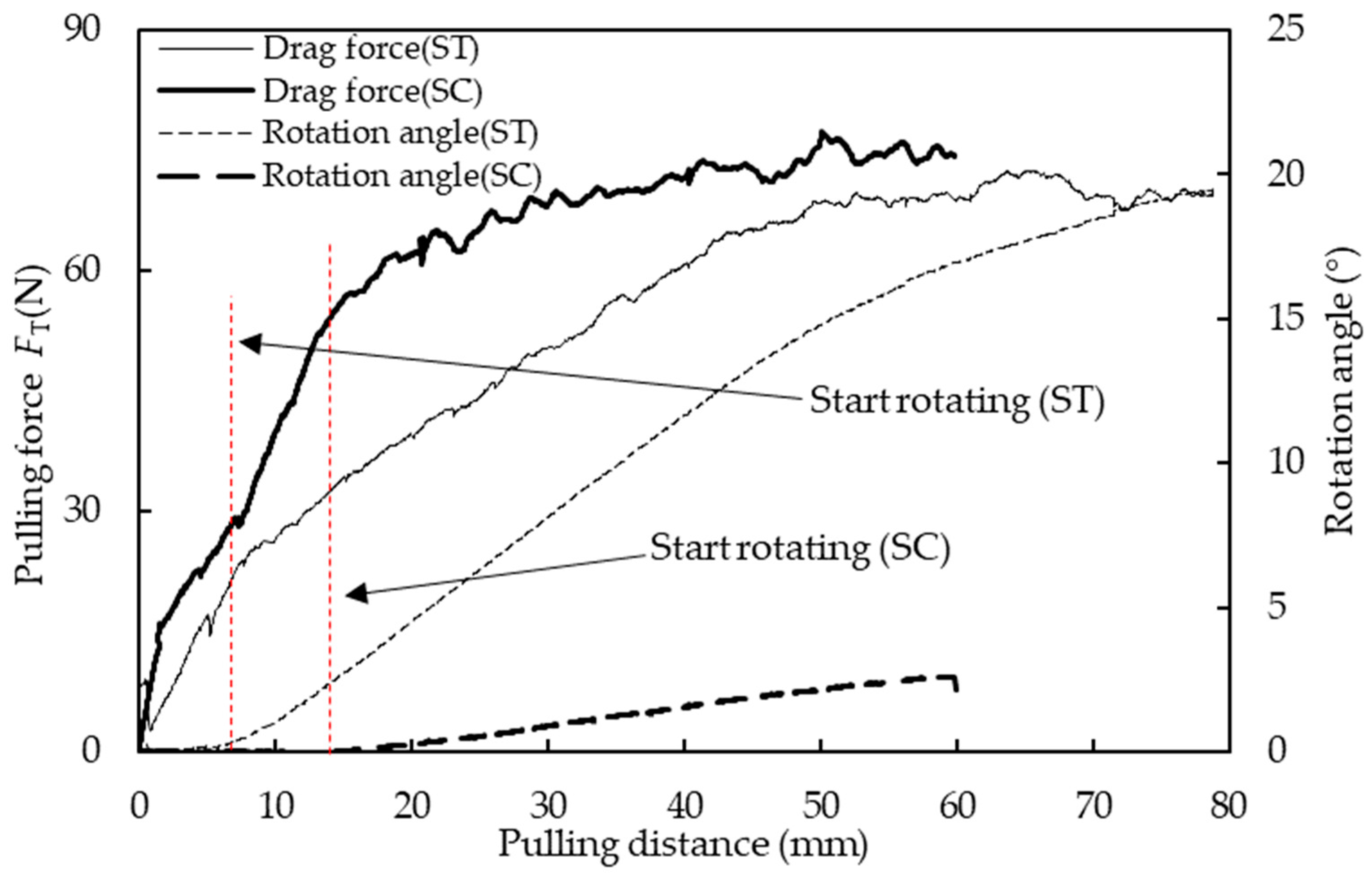
The measured pulling forces FT and rotation angles of square skirted anchor in the two model tests are shown in Figure 4.
It can be seen that the pulling force of the square skirted anchor in both model tests rapidly increased with the increase of the pulling distance, and then reached a stable value. The pulling force value when the mooring point was the top point ST of the side skirt was smaller than that when the mooring point was SC. The maximum pulling force (i.e., bearing capacity, represented as FTU) after stabilization when the mooring point was ST was 68 N. The maximum pulling force when the mooring point was SC was 72 N. The growth slopes of the two pulling force curves significantly decreased when the pulling distance was 7 mm and 14 mm, respectively, as shown by the two vertical dashed lines in Figure 4.
In both tests, the skirted anchor rotated after passing through a certain pulling distance. However, there was a significant difference in the corresponding pulling distance at the beginning of rotation and the final rotation angle. When the mooring point was the top point ST of the side skirt, the skirted anchor rotated earlier (the corresponding pulling distance at the beginning of rotating is shown in Figure 4, which is 7 mm), and the final rotation angle at the end of the test was 20°. When the mooring point was SC, these two values were 14 mm and 2.5°, respectively.
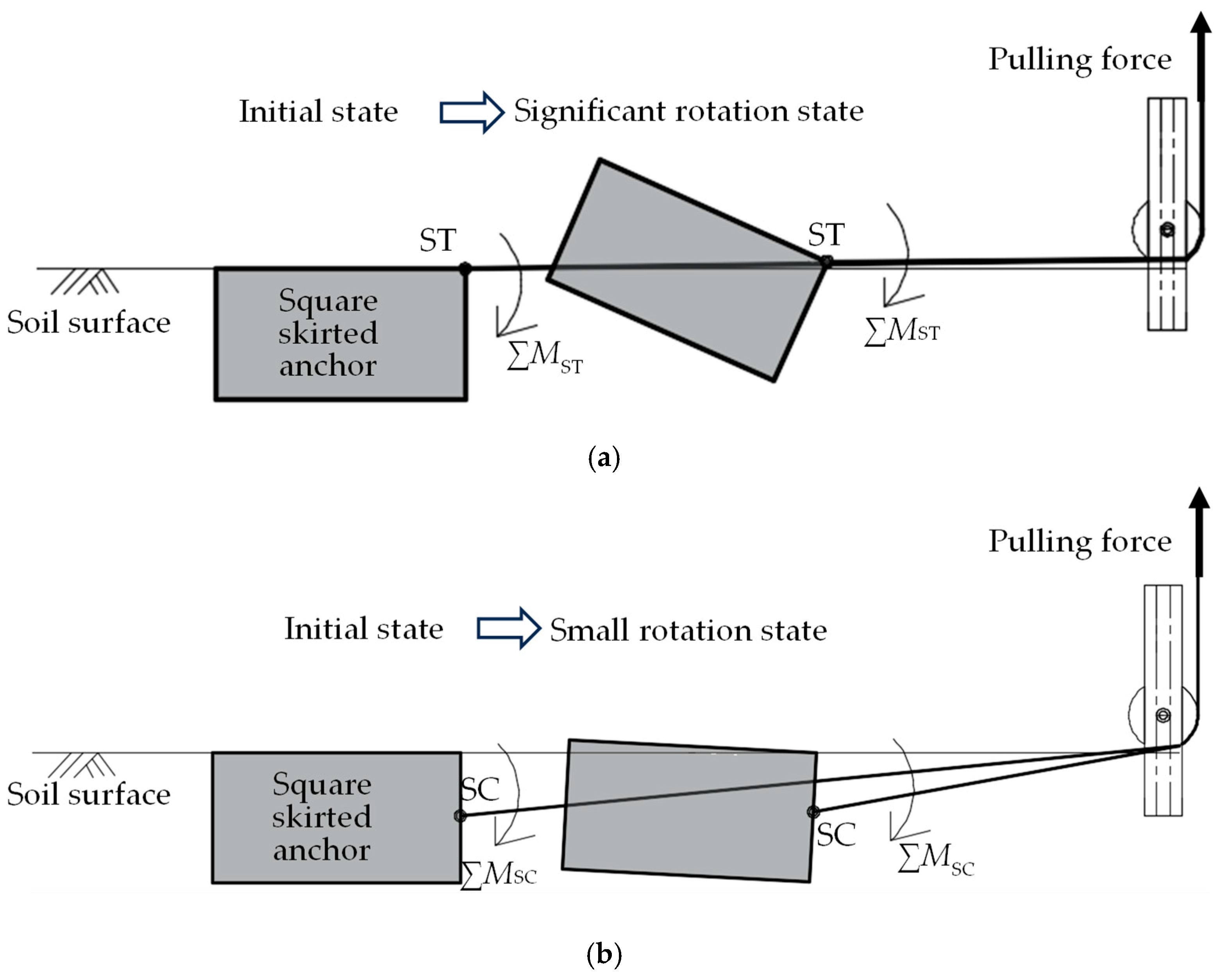
The motion models of the square skirted anchor obtained from two tests are shown in Figure 5. The skirted anchor when the mooring point was ST rotated earlier and underwent greater rotation than the skirted anchor when the mooring point was SC. The reason is that when the mooring point is ST, the soil resistance and pulling force acting on the skirted anchor are not coaxial, resulting in a larger resultant moment. When the mooring point was SC, the resultant moment of the skirted anchor under the combined action of soil resistance and pulling force was small, and the skirted anchor was almost translational, resulting in greater soil resistance.

3. Numerical Modeling

3.1. Model Description

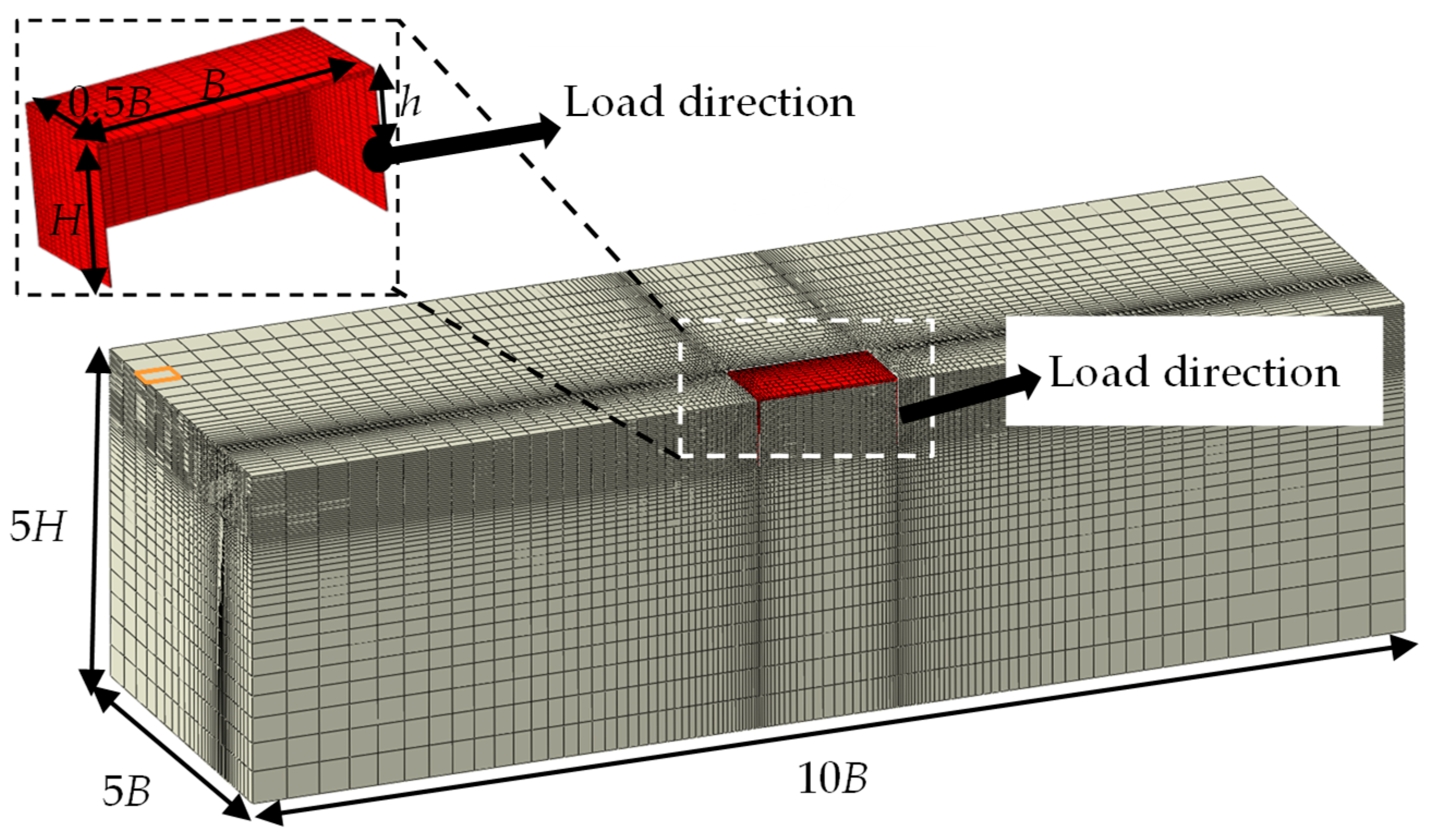
A three-dimensional finite element model was established to study the bearing capacity of a square skirted anchor, as shown in Figure 6. The width and height of the square skirted anchor were B and H, respectively. The thickness of the side skirt was d. The length, width, and height of the soil were set to 10B, 5B, and 5H, respectively. Thus, the boundary effects could be eliminated. The square skirted anchor was in place at the start of the analyses. The influence of factors such as the aspect ratio of the square skirted anchor (i.e., H/B), different mooring point positions (h/H, h is the vertical distance between the top plate of the skirted anchor and the mooring point, as shown in Figure 6), and load inclination angles (i.e., the angle between load and horizontal plane, θ) on the bearing capacity of the skirted anchor was analyzed. To improve the computational efficiency, only half of the skirted anchor and soil were established. The soil element was set as C3D8P element. The mesh configuration was considered. The soil grid near the top plate and side skirt of the square skirted anchor was densified. The minimum size of the soil grid was set to 0.2 times the thickness of the skirt plate of the skirted anchor. The corresponding normal displacements of the outer side surfaces and the six translational and rotational degrees of freedom of the bottom surface were constrained. The symmetry plane of the model adopted symmetry constraints. The top surface of the soil outside the skirted anchor was set as the drainage boundary.
The Modified Cam-Clay (MCC) model was used to describe the constitutive relationship of the soft clay. The Poisson’s ratio of the clay was 0.3. The square skirted anchor was set as a rigid body, with an element type of C3D8. The buoyant density of the square skirted anchor was 6850 kg/m3, and the elastic modulus and Poisson’s ratio were 210 GPa and 0.25, respectively.
The interaction in the tangential direction of the interface between the skirted anchor and the surrounding soil followed the Coulomb friction criterion. The friction coefficient between the skirted anchor and the soil was 0.531. The normal contact between the skirted anchor and the soil interface was set to allow detachment.
The commonly used loading methods include the swipe method and probe method. The swipe method can obtain the failure envelope of the foundation with fewer calculations, but it may underestimate the bearing capacity of embedded foundations [36,37]. The probe method can only obtain one working condition for each calculation, which is more accurate in predicting the failure envelope of embedded foundations. It can also obtain the distributions of the displacement and stress of the foundation and soil to reveal the failure mode [29,36,37,38,39]. Thus, the displacement controlled “Probe” method was used in this paper. A uniformly increasing displacement at a certain angle (θ) was applied to the mooring point of the square skirted anchor and the resulting reaction force was the pulling force.

3.2. Verification

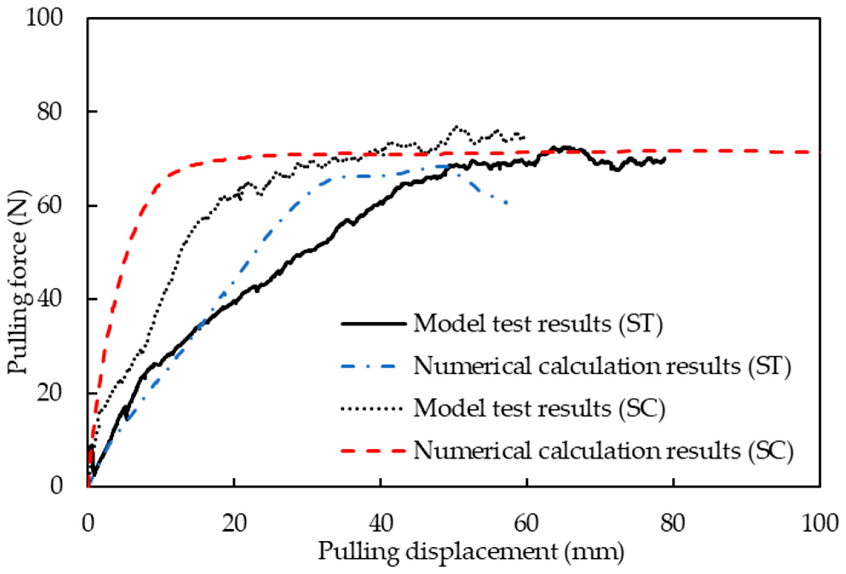
The finite element method was used to predict the bearing capacity of the experimental model anchor at mooring points ST and SC, and the numerical results were compared with the measured results of the model test, as shown in Figure 7. The growth slopes of the pulling force and the maximum pulling force (bearing capacity) of the skirted anchor under different mooring point conditions obtained from numerical calculations are in good agreement with the model test results, verifying the accuracy of the numerical calculation method.

3.3. Calculation Scheme

As shown in Figure 8, the width B of the prototype square skirted anchor was 6.0 m, and four different aspect ratios H/B were adopted: 0.25, 0.5, 1.0, and 2.0. For each square skirted anchor, five mooring points located on the centerline of the side skirt of the anchor were selected, as shown in Figure 6, with h/H values of 0, 0.25, 0.5, 0.75, and 1. The inclined pulling forces (displacement controlled) with seven load inclination angles θ (0°, 15°, 30°, 45°, 60°, 75°, and 90°) were separately applied to each mooring point. The same parameters of the soil and the square skirted anchor used in the model tests were adopted. A total of 140 jobs were calculated, as shown in Table 2.

3.4. Failure Mechanism and Bearing Capacity

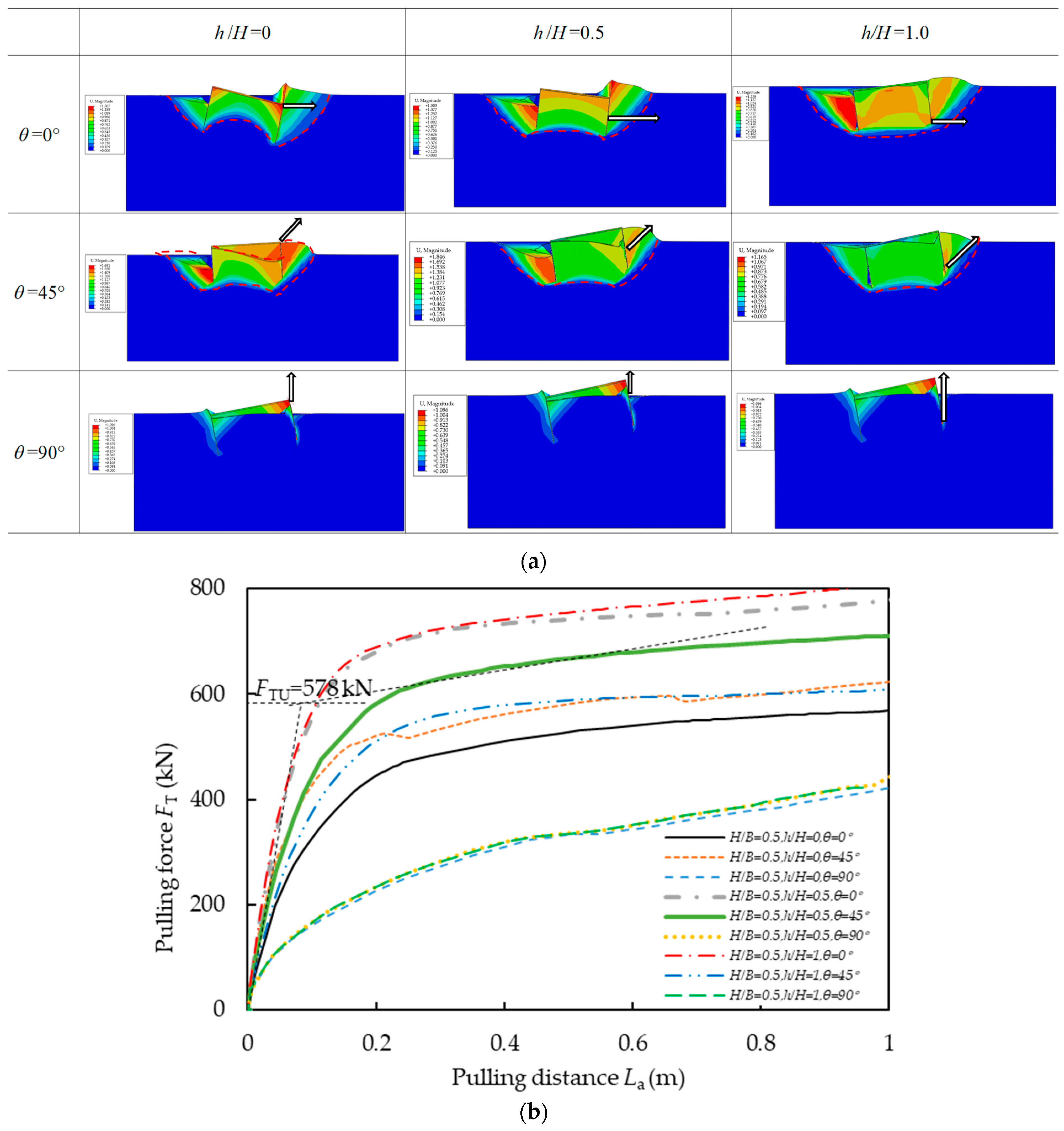
The displacement contours and the variation of the pulling force with the pulling distance are, respectively, shown in Figure 9a,b for the prototype square skirted anchor with an aspect ratio of H/B = 0.5 under different pulling load inclination angles at different mooring points.
Figure 9a shows that when the load inclination angle θ is 0° or 45° (the pulling force is horizontal or inclined), the soil at the leading side of the skirted anchor gradually rises and forms a sliding passive soil wedge where the displacement is significantly greater than that of the surrounding soil. The soil at the trailing side of the skirted anchor detaches from the skirted anchor and a smaller volume of soil collapses. When the pulling force is purely vertical (θ = 90°), the skirted anchor rotates counterclockwise with upward motion. The interaction between the leading edge of the skirted anchor and the surrounding soil exhibits significant tangential shear. The soil behind the trailing side of the skirted anchor is compressed to form a smaller volume of passive soil wedge.
The location of mooring point (h/H) has the greatest impact on the failure mode of the skirted anchor subjected to horizontal loads (θ = 0°). When θ = 0°, as the mooring point position moves downwards, i.e., h/H gradually increases from 0 to 1, the rotation mode of the skirted anchor changes from clockwise to counterclockwise, and the failure mechanism skirted anchor changes from a rotating convex spoon at the bottom of the skirted anchor to horizontal sliding across the foundation base level. The change in mooring point position has a relatively small impact on the failure mode of the skirted anchors subjected to inclined or pure vertical loads. As the mooring point position moves downwards, the failure mode of the skirted anchor does not change significantly.
The development curves of the pulling force FT–pulling displacement La of the skirted anchor in Figure 9b shows that all the pulling force FT under different conditions continuously increases with increasing pulling distance La. The maximum pulling force is observed when H/B = 0.5, h/H = 1.0, and θ = 0°. The minimum pulling force is observed when H/B = 0.5, h/H = 0, and θ = 90°. Because none of the three FTLa curves shown in Figure 9b have a clear peak value of the pulling force (i.e., the bearing capacity FTu), the method shown in Figure 9b is used to determine the bearing capacity of the skirted anchor. That is, the bearing capacity FTu is determined based on the intersection point of the tangent lines of the two sections of the FTLa curve, which rapidly increases in the initial stage and slowly increases in the later stage. Therefore, the bearing capacity FTu under different conditions can be determined. Taking the case of h/H = 0.5 and θ = 45° in Figure 9b as an example, the bearing capacity FTu can be determined as 578 kN.
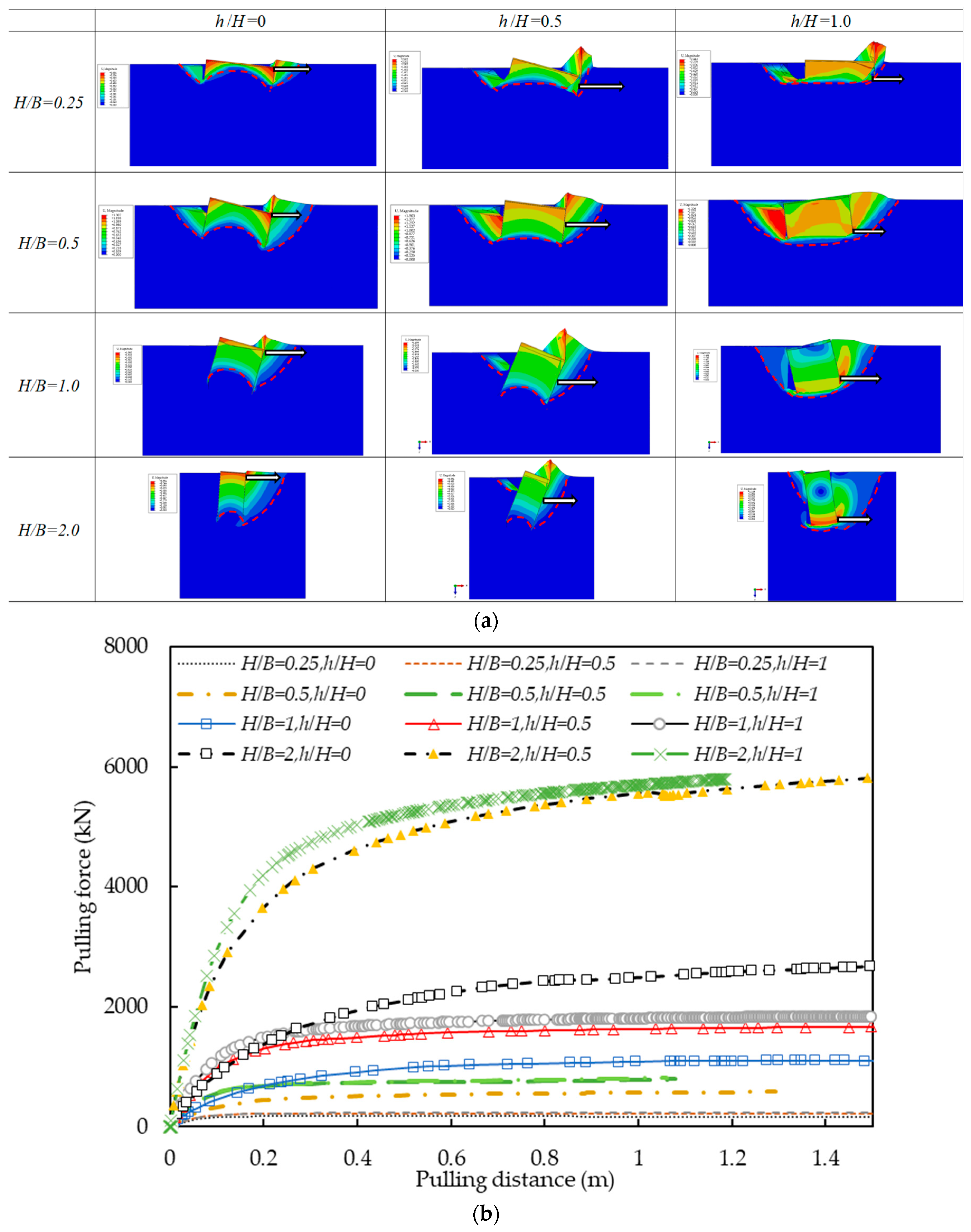
Figure 10a,b show the displacement contours and the variation of the pulling force with the pulling distance for the prototype square skirted anchor subjected to pure horizontal loads with different aspect ratios and different mooring points, respectively.
From Figure 10a, it can be seen that when the mooring point position h/H is 0 or 0.5, the failure mechanism is clockwise rotation for all square skirted anchors with different aspect ratios. When h/H is 1.0, the failure modes of all skirted anchors with different aspect ratios include translation and counterclockwise rotation. This indicates that when h/H is 0 or 0.5, the resultant moment of the pulling force, normal and tangential reaction forces, of the soil acting on the square skirted anchor is clockwise. The optimal depth of the horizontal load point (i.e., mooring point position h/H) is between 0.5 and 1.0, at which the resultant moment of the skirted anchor is balanced. The pulling force curves in Figure 10b can also be used to obtain the bearing capacity FTu under these different conditions.

3.5. Failure Envelopes

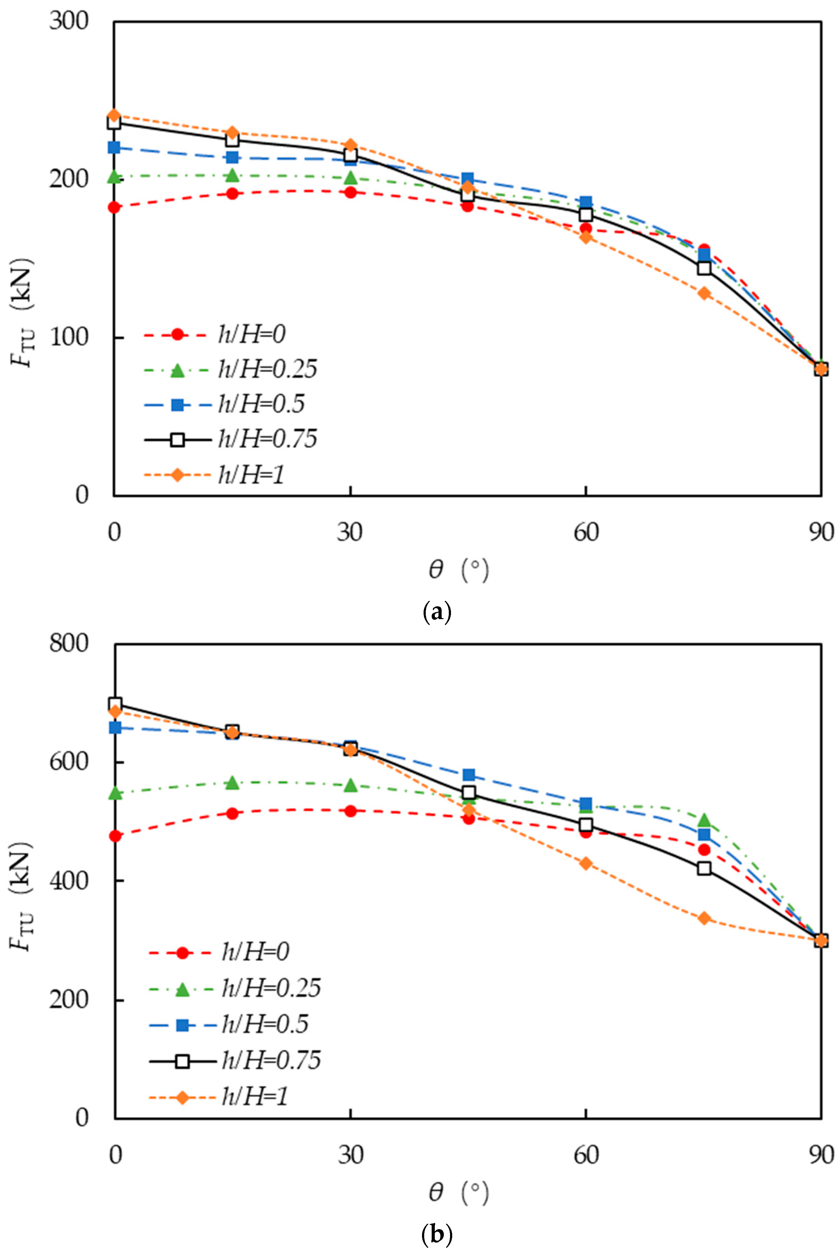
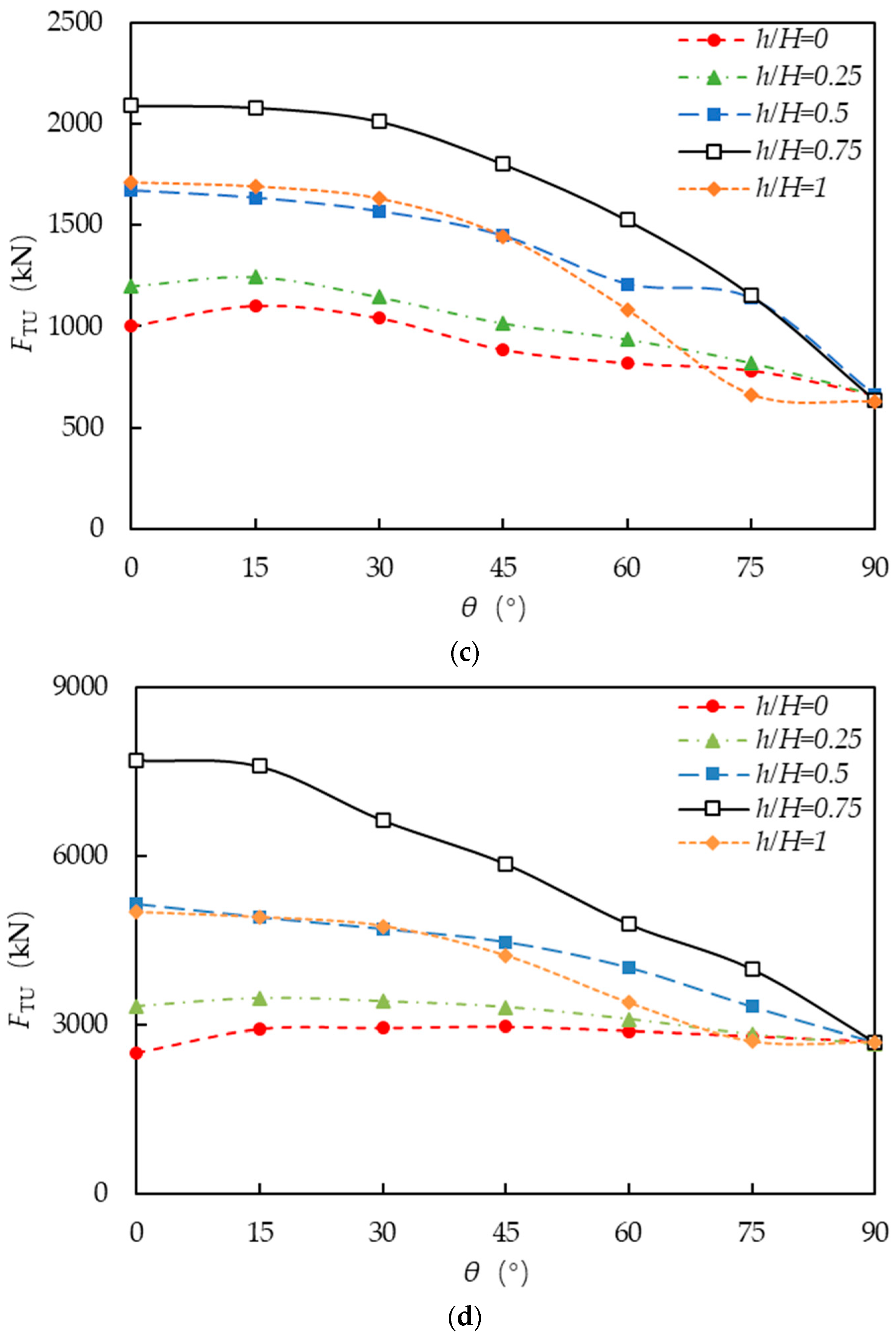
The bearing capacity of the skirted anchor under different aspect ratios, load inclination angles, and mooring point positions obtained from all 140 calculation conditions mentioned above are presented in Figure 11.
Figure 11 shows that the bearing capacity of the square skirted anchor is the highest when the load inclination angle θ is within the range of 0~30°. For the square skirted anchors with smaller aspect ratios (H/B = 0.25 and 0.5), the maximum bearing capacity is achieved at the mooring point position h/H = 0.5. As the aspect ratio of the skirted anchor increases to 1.0 and 2.0, the maximum bearing capacity of the skirted anchor is achieved at the mooring point position h/H = 0.75. This is consistent with the observations from Figure 10 shown earlier.
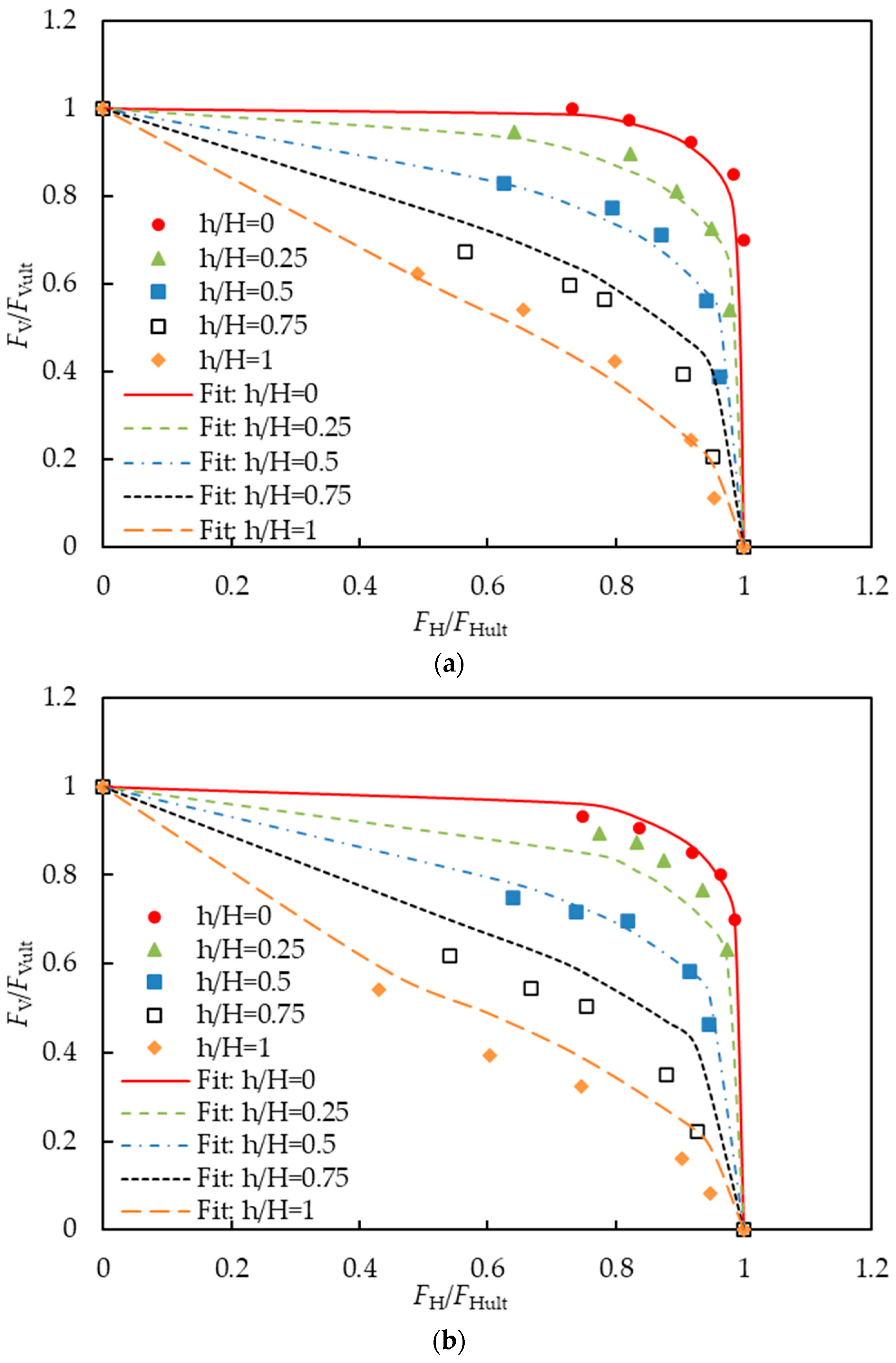
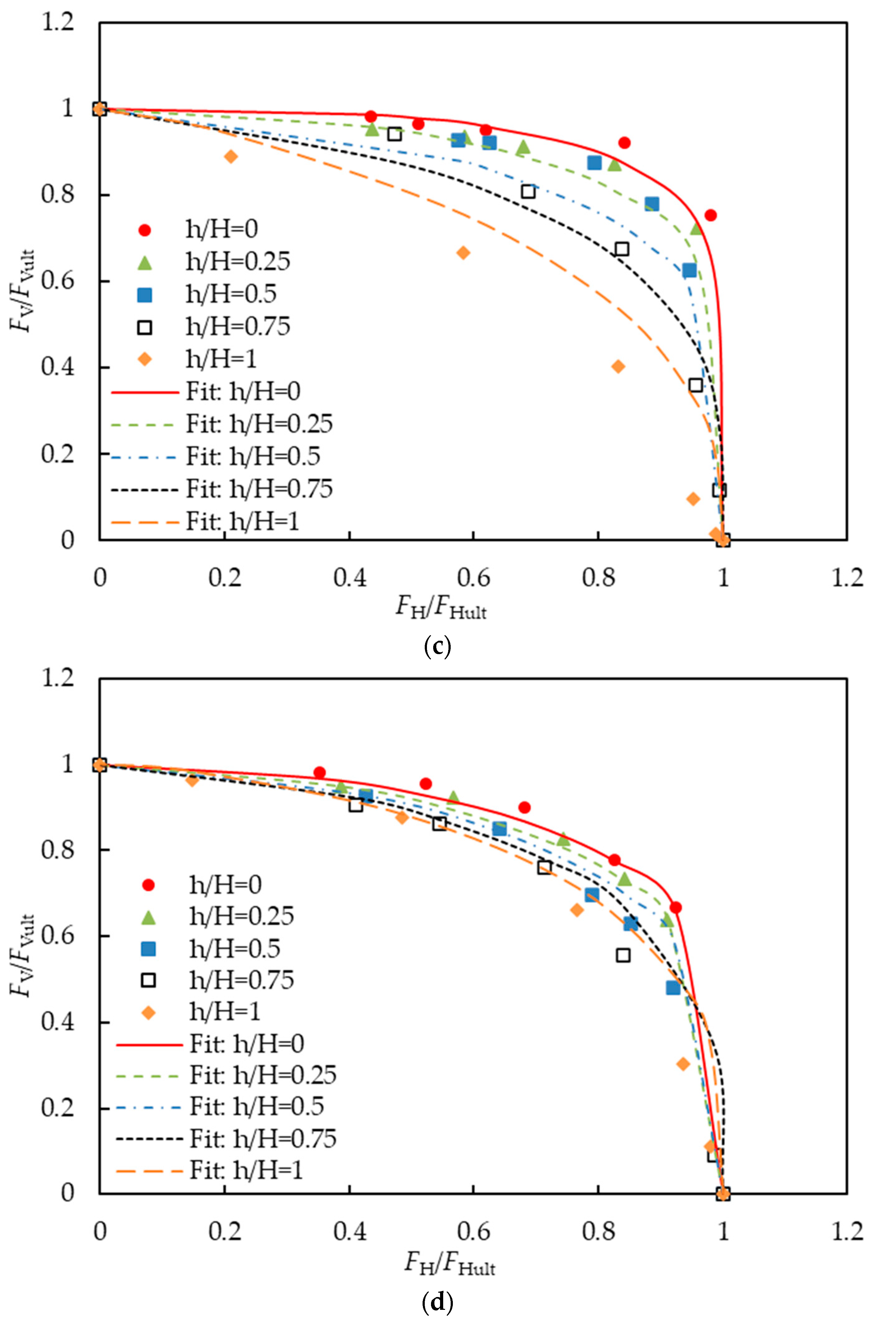
The normalized failure envelopes of the square skirted anchors in the horizontal and vertical load space (V-H) are plotted, as shown in Figure 12, where FV and FH are the vertical and horizontal reaction force, and FVult and FHult are the corresponding maximum uniaxial reaction forces.
Based on the skirted anchor results shown in Figure 12, a curve-fitting formula is proposed to describe the normalized failure envelopes of the square skirted anchor by using the least squares method based on the Levernberg–Marquardt algorithm on the basis of the ellipse formula, accounting for the aspect ratio H/B and the mooring point position h/H.
F H F H u l t a + F V F V u l t b = 1
where a and b are exponents related to the aspect ratio H/B of the skirted anchor and the position of the load attachment point h/H, which are fitted using the least squares method with exponential and liner functions, respectively, as shown in Equation (2).
a = 2.94 H B 0.64 10.155 0.16 H B + 0.1 1 e h H 0.1528 + 0.094 ( H B ) b = 2.772 H B 7.04 h H 2.12 H B + 8.94

4. Conclusions

In this article, two model tests were conducted to study the failure mechanisms and the bearing capacity of square skirted anchors with different load attachment points in clay. It was found that, when the load attachment point was located at the top point of the side skirt (ST), the skirted anchor was more prone to flipping, and the obtained bearing capacity was smaller than the bearing capacity at the midpoint of the side skirt (SC).
The bearing behavior of four skirted anchors with different aspect ratios was studied using a three-dimensional finite element method under five different mooring points and seven different load inclination angles. The results showed that the bearing performance of the square skirted anchor was optimal when the load inclination angle θ ranged from 0 to approximately 30°. For skirted anchors with smaller aspect ratios (H/B = 0.25 and 0.5), the optimal bearing capacity was achieved at the mooring point position of h/H = 0.5. As the aspect ratio of the skirted anchor increased to 1.0 and 2.0, the bearing capacity of the skirted anchor performed best at the mooring point position h/H = 0.75.
The bearing capacity of the square skirted anchor under 140 working conditions was summarized, and the failure envelope curves of the bearing capacity of the square skirted anchor in the V-H space were drawn. A formula for the bearing capacity of the skirted anchor was fitted, accounting for the influence of factors such as the aspect ratio H/B of the skirted anchor and the position of the mooring point h/H.
This paper mainly focused on the bearing characteristics of skirt anchors in saturated clay. Considering the complex environmental and geological distribution conditions of the skirted anchors, more research methods are needed to study the bearing capacity of skirted anchors, such as using more advanced constitutive models or directly conducting on-site tests.

Author Contributions

Conceptualization, S.L. and Y.R.; methodology, S.L. and Y.W.; software, Y.W. and Y.R.; validation, Y.W. and Y.R.; formal analysis, Y.W., S.L., L.S. and Y.R.; investigation, Y.W., S.L., L.S. and Y.R.; resources, S.L.; data curation, Y.W.; writing—original draft preparation, Y.W. and Y.R.; writing—review and editing, Y.W., S.L., L.S. and Y.R.; visualization, Y.W., S.L., L.S. and Y.R.; supervision, S.L. and L.S.; project administration, S.L.; funding acquisition, Y.R. and S.L. All authors have read and agreed to the published version of the manuscript.

Funding

This research was funded by the National Natural Science Foundation of China, grant number 52108335, 52078336, 42277133.

Institutional Review Board Statement

Not applicable.

Informed Consent Statement

Not applicable.

Data Availability Statement

Data are contained within the article.

Conflicts of Interest

The authors declare no conflicts of interest.

References

  1. Ding, H.; Zhu, Y.; Zhang, P.; Le, C. Optimal skirt spacing for subsea skirted foundation considering floating stability. Trans. Tianjin Univ. 2017, 23, 445–450. [Google Scholar] [CrossRef]
  2. Feng, X.; Gourvenec, S.; Randolph, F.M. Optimal skirt spacing for subsea mudmats under loading in six degrees of freedom. Appl. Ocean Res. 2014, 48, 10–20. [Google Scholar] [CrossRef]
  3. Choo, Y.W.; Kang, T.W.; Seo, J.H.; Youn, J.U.; Hossain, M.S. Centrifuge study on undrained and drained behaviors of a laterally loaded bucket foundation in a silty sand. In Proceedings of the International Ocean and Polar Engineering Conference, Big Island, HI, USA, 21–26 June 2015. [Google Scholar]
  4. Fu, D.; Gaudin, C.; Bienen, B.; Tian, Y.; Cassidy, J.M. Combined load capacity of a preloaded skirted circular foundation in clay. J. Geotech. Geoenviron. Eng. 2018, 144, 04018084. [Google Scholar] [CrossRef]
  5. Gourvenec, S.; Randolph, F.M. Consolidation beneath circular skirted foundations. Int. J. Geomech. 2010, 10, 22–29. [Google Scholar] [CrossRef]
  6. Hu, Y.; Randolph, F.M.; Watson, P.G. Bearing response of skirted foundation on nonhomogeneous soil. J. Geotech. Geoenviron. Eng. 1999, 125, 924–935. [Google Scholar] [CrossRef]
  7. Mehravar, M.; Harireche, O.; Faramarzi, A. Evaluation of undrained failure envelopes of caisson foundations under combined loading. Appl. Ocean Res. 2016, 59, 129–137. [Google Scholar] [CrossRef]
  8. Sun, L.; Zhang, Y.; Feng, X.; Gourvenec, S.; Li, S. Upper-bound solutions for inclined capacity of suction caissons in a trenched seabed. Géotechnique 2023, 74, 473–485. [Google Scholar] [CrossRef]
  9. Zhang, Y.; Wang, Y.; Li, D.; Mao, D. Bearing capacity and soil deformation around modified suction caisson in clay under monotonic horizontal loading. Mar. Georesour. Geotechnol. 2023, 41, 959–968. [Google Scholar] [CrossRef]
  10. Zhu, B.; Zhang, W.; Ying, P.; Chen, Y. Deflection-Based Bearing Capacity of Suction Caisson Foundations of Offshore Wind Turbines. Geotech. Geoenviron. Eng. 2014, 140, 04014013. [Google Scholar] [CrossRef]
  11. Bienen, B.; Gaudin, C.; Cassidy, M.J. Numerical modelling of a hybrid skirted foundation under combined loading. Comput. Geotech. 2012, 45, 127–139. [Google Scholar] [CrossRef]
  12. Cai, W.; Zhan, J.; Gong, Y. Further investigation of the six-DOF hollow gravity anchor: Impact of the internal slant angle. Mar. Struct. 2017, 56, 85–98. [Google Scholar] [CrossRef]
  13. Houlsby, G.; Kelly, R.; Huxtable, J.; Byrne, B. Field trials of suction caissons in clay for offshore wind turbine foundations. Géotechnique 2005, 55, 287–296. [Google Scholar] [CrossRef]
  14. Li, D.; Feng, L.; Zhang, Y. Model tests of modified suction caissons in marine sand under monotonic lateral combined loading. Appl. Ocean Res. 2014, 48, 137–147. [Google Scholar] [CrossRef]
  15. Li, D.; Zhang, Y.; Feng, L. Capacity of modified suction caissons in marine sand under static horizontal loading. Ocean Eng. 2015, 102, 1–16. [Google Scholar] [CrossRef]
  16. Watson, P.G.; Randolph, F.M. Failure envelopes for caisson foundations in calcareous sediments. Appl. Ocean Res. 2018, 20, 83–94. [Google Scholar] [CrossRef]
  17. Martin, C.M. Physical and Numerical Modelling of Offshore Foundations under Combined Loads. Ph.D. Thesis, Oxford University, Oxford, UK, 1994. [Google Scholar]
  18. Martin, C.M.; Houlsby, G.T. Combined loading of spudcan foundations on clay: Numerical modelling. Géotechnique 2001, 51, 687–699. [Google Scholar] [CrossRef]
  19. Sloan, S.W. Lower bound limit analysis using finite elements and linear programming. Int. J. Numer. Anal. Methods Geomech. 1988, 12, 61–77. [Google Scholar] [CrossRef]
  20. Sun, M.; Zhao, S.; Li, W.; Sun, Z.; Peng, M.; Xu, H. Probabilistic analysis on the lateral capacity of suction caissons in spatially variable soils. Mar. Georesour. Geotechnol. 2023, 42, 1011–1022. [Google Scholar] [CrossRef]
  21. Tang, X.; Zhang, X.; Shao, Q.; Li, Z. Rotation Center and Horizontal Bearing Capacity of the Bucket Foundation in Soft Ground. Mar. Georesour. Geotechnol. 2015, 34, 594–601. [Google Scholar] [CrossRef]
  22. Sloan, S.W.; Kleeman, P.W. Upper bound limit analysis using discontinuous velocity fields. Comput. Methods Appl. Mech. Eng. 1995, 127, 293–314. [Google Scholar] [CrossRef]
  23. Yu, J.; Wang, H.; Huang, M.; Leung, C.F. Upper-bound analysis of laterally loaded rigid monopiles in clay with linearly increasing strength. Can. Geotech. J. 2021, 58, 1289–1304. [Google Scholar] [CrossRef]
  24. He, B.; Jiang, J.; Cheng, J.; Zheng, J.; Wang, D. The capacities of tripod bucket foundation under uniaxial and combined loading. Ocean Eng. 2021, 220, 108400. [Google Scholar] [CrossRef]
  25. Fan, K.; Guan, Y.; Zhu, X.; Li, W.; Tang, Y.; Chen, Y. Investigation of composite bucket foundation bearing characteristics in various soil properties. Mar. Georesour. Geotechnol. 2023, 41, 1175–1186. [Google Scholar] [CrossRef]
  26. Singam, N.K.; Chatterjee, S. Effect of Torsion on Failure Mechanism and Undrained Horizontal Capacity of Tripod Bucket Foundations in Clay. Int. J. Geomech. 2023, 23, 04023100. [Google Scholar] [CrossRef]
  27. Gourvenec, S.; Jensen, K. Effect of embedment and spacing of cojoined skirted foundation systems on undrained limit states under general loadin. Int. J. Geomech. 2009, 9, 267–279. [Google Scholar] [CrossRef]
  28. Supachawarote, C.; Randolph, F.M.; Gourvenec, S. Inclined pull-out capacity of suction caissons. In Proceedings of the 14th International Offshore and Polarengineering Conference, Toulon, France, 23–28 May 2004. [Google Scholar]
  29. Yun, G.; Bransby, M.F. The horizontal-moment capacity of embedded foundations in undrained soil. Can. Geotech. J. 2007, 44, 409–424. [Google Scholar] [CrossRef]
  30. Ukritchon, B.; Whittle, A.J.; Sloan, S.W. Undrained Limit Analyses for Combined Loading of Strip Footings on Clay. J. Geotech. Geoenviron. Eng. 1998, 124, 265–276. [Google Scholar] [CrossRef]
  31. Wang, D.; Jin, X. Finite Element Analysis of Laterally Loaded Suction Caisson in Anisotropic Clay. China Ocean Eng. 2006, 20, 665–672. [Google Scholar]
  32. Feng, T.; Wei, Y.; Zhang, J.; Liu, L. Capacity of a multi-compartment single-bucket breakwater structure in silt-over-clay under combined V-H-M loading. Mar. Georesour. Geotechnol. 2023, 41, 1309–1324. [Google Scholar] [CrossRef]
  33. Zhan, Y.; Liu, F. Numerical Analysis of Bearing Capacity of Suction Bucket Foundation for Offshore Wind Turbines. Electron. J. Geotech. Eng. 2010, 15, 76–81. [Google Scholar]
  34. Aubeny, C.; Han, S.W.; Murff, J.D. Suction caisson capacity in anisotropic, purely cohesive soil. Int. J. Geomech. 2003, 3, 225–235. [Google Scholar] [CrossRef]
  35. Vulpe, C.; Gourvenec, S.; Cornelius, A.F. Effect of embedment on consolidated undrained capacity of skirted circular foundations in soft clay under planar loading. Can. Geotech. J. 2017, 54, 158–172. [Google Scholar] [CrossRef]
  36. Gourvenec, S.; Randolph, F.M. Effect of strength non-homogeneity on the shape and failure envelopes for combined loading of strip and circular foundations on clay. Géotechnique 2003, 53, 575–586. [Google Scholar] [CrossRef]
  37. Gourvenec, S. Undrained bearing capacity of embedded footings under general loading. Géotechnique 2008, 58, 177–185. [Google Scholar] [CrossRef]
  38. Bienen, B.; Byrne, B.W.; Houlsby, G.T.; Cassidy, M.J. Investigating six-degree-of-freedom loading of shallow foundations on sand. Géotechnique 2006, 56, 367–379. [Google Scholar] [CrossRef]
  39. Feng, X.; Randolph, F.M.; Gourvenec, S.; Wallerand, R. Design approach for rectangular mudmats under fully three-dimensional loading. Géotechnique 2014, 64, 51–63. [Google Scholar] [CrossRef]
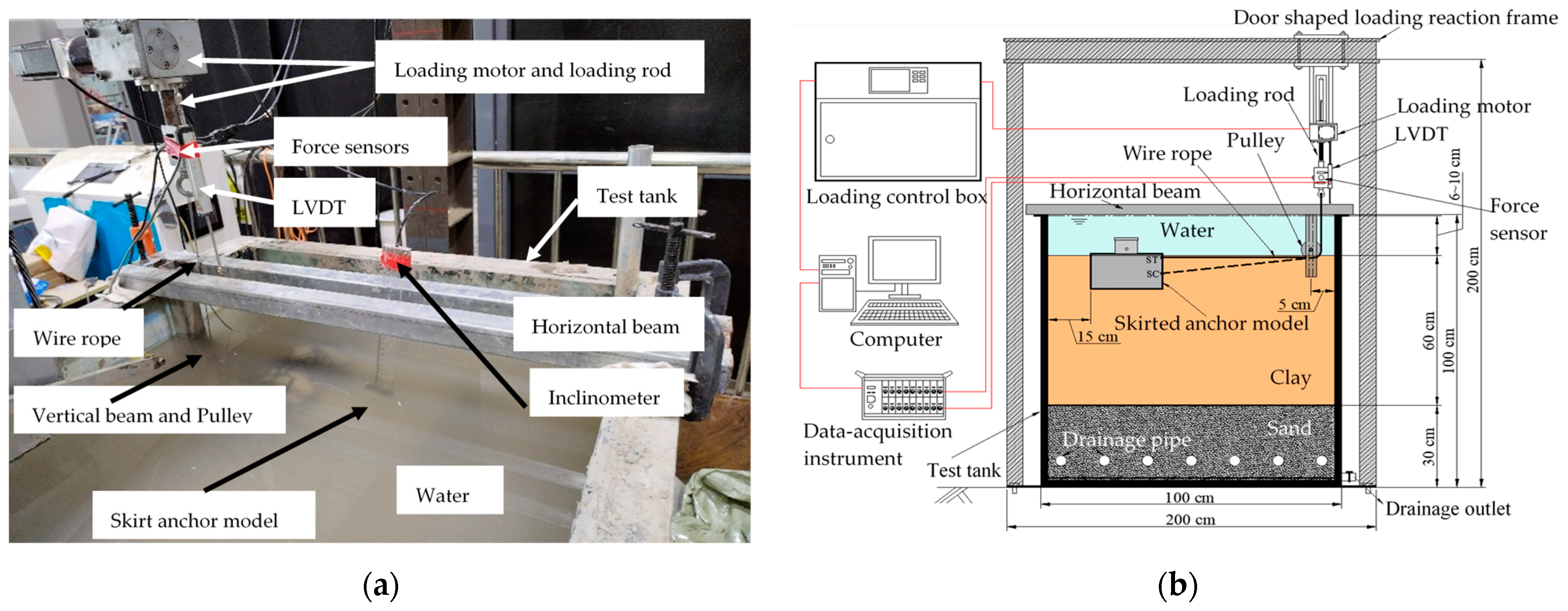
Figure 1. Model test setup: (a) photo; (b) diagram.
Jmse 12 01572 g001
Figure 2. Square skirted anchor model.
Jmse 12 01572 g002
Figure 3. Distribution of the undrained shear strength of clay with depth.
Jmse 12 01572 g003
Figure 4. Measured pulling forces and rotation angles.
Jmse 12 01572 g004
Figure 5. Motion models diagram of square skirted anchor with different mooring points: (a) ST; (b) SC.
Jmse 12 01572 g005
Figure 6. Finite element model of the bearing capacity of a square skirted anchor.
Jmse 12 01572 g006
Figure 7. Comparison between measured and calculated pulling forces.
Jmse 12 01572 g007
Figure 8. Schematic diagram of the finite element model for parameter analysis.
Jmse 12 01572 g008
Figure 9. Numerical results under different mooring point positions h/H and different load inclination angles θ when H/B = 0.5: (a) displacement contours; (b) pulling force vs. pulling distance.
Jmse 12 01572 g009
Figure 10. Numerical results under different aspect ratios H/B and different mooring points h/H when θ = 0°: (a) displacement cloud maps; (b) pulling force vs. pulling distance curves.
Jmse 12 01572 g010
Figure 11. Bearing capacity of square skirted anchors with different aspect ratios H/B: (a) H/B = 0.25; (b) H/B = 0.5; (c) H/B = 1.0; and (d) H/B = 2.0.
Jmse 12 01572 g011aJmse 12 01572 g011b
Figure 12. Failure envelope curves of square skirted anchors with different aspect ratios: (a) H/B = 0.25; (b) H/B = 0.5; (c) H/B = 1.0; and (d) H/B = 2.0.
Jmse 12 01572 g012aJmse 12 01572 g012b
Table 1. Clay parameters.
ParameterValue
Slope of the critical state line CSL in p′-q space, M (-)1.2
Slope of the normal consolidation line NCL in the e-lnp′ space, λ (-)0.22
Slope of the unloading rebound line SL in the e-lnp′ space, κ (-)0.055
Intercept of the critical state line CSL in e-lnp′ space, ecs (-)1.9
Effective weight of soil, γ′ (kN/m3)6
Poisson’s ratio of soil, μ (-)0.33
Soil permeability coefficient, k (m/s)1 × 10−9
Table 2. Summary of calculation conditions.
VariablesValues
Aspect ratio H/B0.25, 0.5, 1.0, 2.0
Load inclination angle θ0°, 15°, 30°, 45°, 60°, 75°, 90°
Mooring point h/H0, 0.25, 0.5, 0.75, 1.0
Disclaimer/Publisher’s Note: The statements, opinions and data contained in all publications are solely those of the individual author(s) and contributor(s) and not of MDPI and/or the editor(s). MDPI and/or the editor(s) disclaim responsibility for any injury to people or property resulting from any ideas, methods, instructions or products referred to in the content.