Article

Pitching Stabilization Control for Super Large Ships Based on Double Nonlinear Positive Feedback under Rough Sea Conditions

Navigation and Ship Engineering College, Dalian Ocean University, Dalian 116023, China
*
Author to whom correspondence should be addressed.
J. Mar. Sci. Eng. 2024, 12(9), 1657; https://doi.org/10.3390/jmse12091657
Submission received: 25 June 2024 / Revised: 29 August 2024 / Accepted: 29 August 2024 / Published: 16 September 2024
(This article belongs to the Special Issue Global Navigation Satellite System for Maritime Applications)

Abstract

:
Due to the rapid development of a global navigation satellite system and the rapid growth of ships, the traditional control algorithms are not suitable; hence, the longitudinal rocking phenomenon generated by external disturbances is more serious when a ship is sailing. This paper takes a mathematical model of the super large oil tanker “KVLCC2”’s longitudinal motion as the controlled plant, establishing a multi-input multi-output instability control system, using the root trajectory shaping method and a weighting matrix to ensure the stability of its transfer function’s mathematical model. An improved closed-loop gain-shaping algorithm is utilized to design a simple robust controller. And a dual nonlinear positive feedback control algorithm is added to the control system to further improve the controller’s pitching stabilization performance and reduce the controller’s output energy. In order to verify that the controller has a consistently strong robustness, simulation experiments are carried out by adding a level 6, 7 and 8 wind wave model and a perturbation link to the control system, respectively. The results show that when the value of the hysteresis constant is taken as 0.25, the output values of the heave displacement and the pitch angle are greatly reduced, and the longitudinal rocking phenomenon is significantly improved. The dual nonlinear positive feedback control algorithm enhances the ship’s pitching stabilization control capability and further reduces the controller’s output energy, which provides technical support for the smooth and efficient sailing of super large ships under changing sea conditions. Combined with a global navigation satellite system, this algorithm provides a new method for pitching stabilization control of super large ships.

1. Introduction

With the development of global satellite navigation control in the navigation field, the safety and real-time monitoring of ship transportation at sea have been greatly improved. As one of the most important means of maritime transportation, ships play an important role in most international trade and cargo transportation. At present, there are many types of ships used in the maritime transportation industry, mainly including container ships, bulk carriers, oil tankers and liquefied natural gas vessels [1,2]. During ship navigation, ships are always affected by external environmental disturbances, such as sea wind, waves, currents and other objective factors. These cause the ship to translate and rotate around each of its three axes, resulting in six degrees of freedom. The effects of pitch and heave motion are particularly serious [3].
Pitching can have the effects such as increased hull stress, reduced crew comfort, reduced sailing stability and increased fuel consumption. Ni Jun [4] utilized a mechanical structure to manipulate the motion of rocking reduction fins and made the rocking reduction fins and fluid move against each other. As a result, an anti-swaying moment was generated on the surface of the fins to achieve a sway reduction effect. However, the fin stabilizers have a slight pitching stabilization effect at a low speed and even no effect at zero speed. Zhang [5] took a polar research ship as a model and used a proportional–integral–differential (PID) controller to control the swing of the fin stabilizers. When the ship’s speed is zero, the purpose of stabilizing the ship is achieved by controlling the stabilizer fin. This makes up for the disadvantages of conventional fin stabilizers. Huang [6] proposed a new passive anti-longitudinal cross-type rocking rudder which was composed of the original vertical rudder blade, a reaction rudder blade in the horizontal direction and a rudder ball at the intersection. Although the anti-longitudinal rocking rudder has the advantages of simple use, easy maintenance and no additional damping, the device requires a lot of power to realize the pitching stabilization function.
With the development of the ship industry towards intelligent control automation, more control algorithms have been used to control ships’ pitching stabilization, such as fuzzy control, adaptive control, nonlinear feeders, etc. These make up for the shortcomings of the traditional pitching stabilization devices above and improve the flexibility and efficiency of ships’ pitching stabilization systems [7]. Li [8] proposed a new pitching stabilization control algorithm based on algebraic model predictive control (AMPC), and through this, could calculate the heave displacement velocity and the angular velocity, which greatly improved the speed of online calculation. Thus, it achieved the purpose of predictive control and improved the pitching stabilization ability of the control system. Based on model predictive control, Xu [9] proposed a new type of pitching stabilization control method by combining model predictive control and sliding mode control, which enhanced the prediction accuracy and also improved the strong robust performance of the system. Zhang [10] designed a robust controller that used proportional differentiation (PD) and an expansion state observer (ESO). From the simulation results, the effect of pitching stabilization was well controlled, but the controller’s output energy also increased.
In recent years, nonlinear feedback and modification algorithms have been proposed to solve the above problem of controller energy output dissipation [11,12]. Zhang [13] took the “Yukun” ship from Dalian Maritime University as the controlled plant and proposed a nonlinear feedback control algorithm based on the inverse tangent function, and the control effect was significantly improved. Meanwhile, Cao [14] designed a nonlinear modification controller based on the power function. This not only improved the ability of the controller’s pitching stabilization but also saved the controller output energy.
However, the method proposed above is only applicable to good sea conditions, and the rocking reduction effect decreases and the controller’s output energy increases for rough sea conditions. Based on the above incentives, this paper makes the following contributions:
(1)
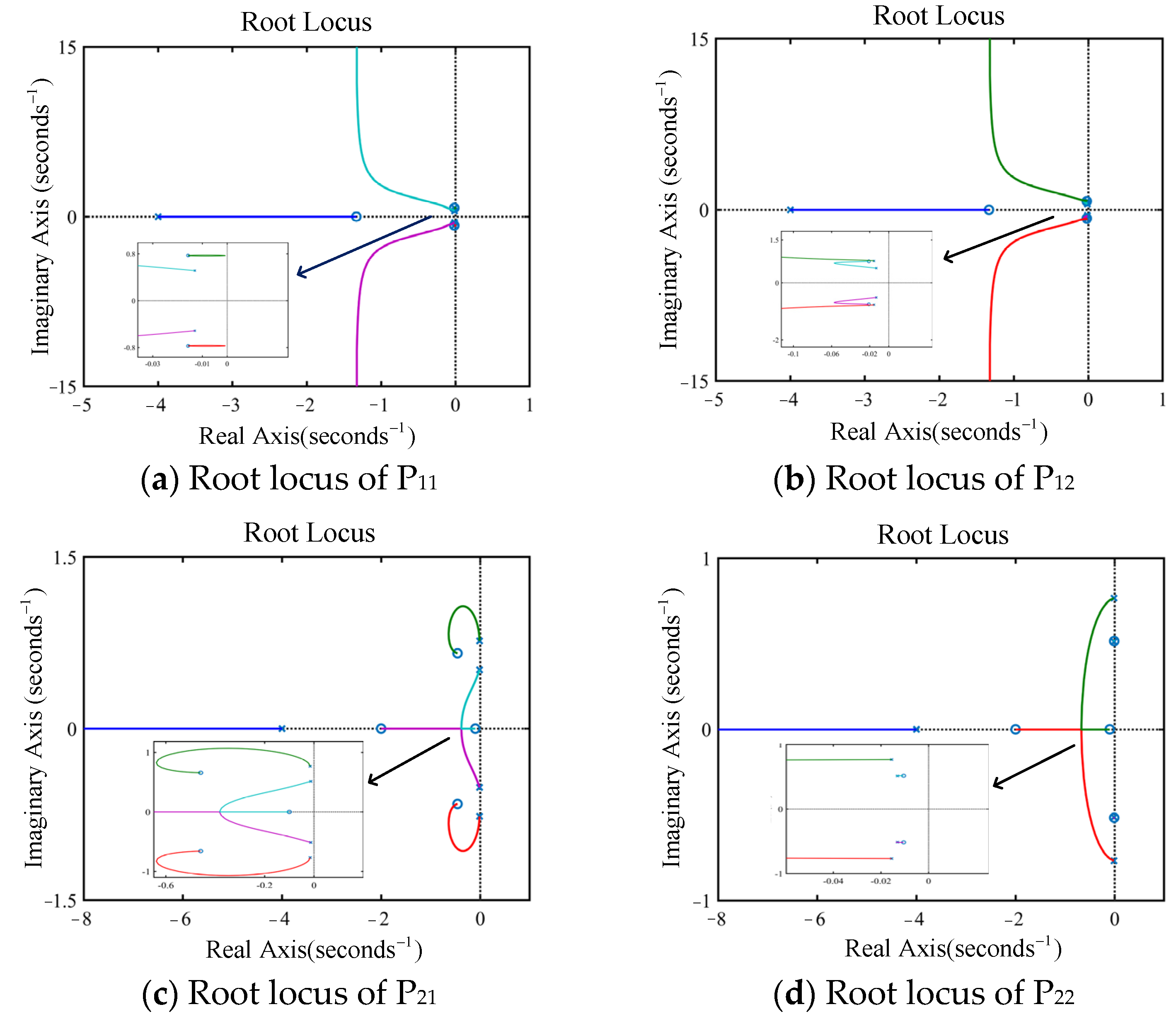
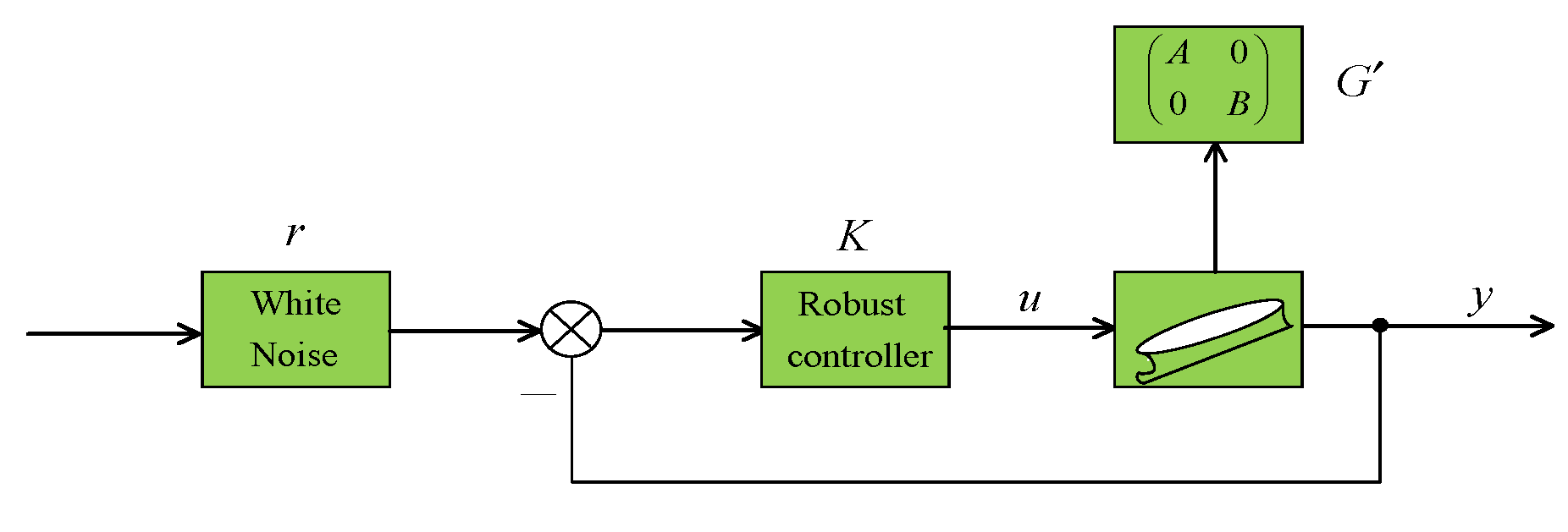
Taking the super large oil tanker “KVLCC2” as the controlled plant, designing a simple robust controller with strong robustness for a multi-input and multi-output (MIMO) unstable mathematical model.
(2)
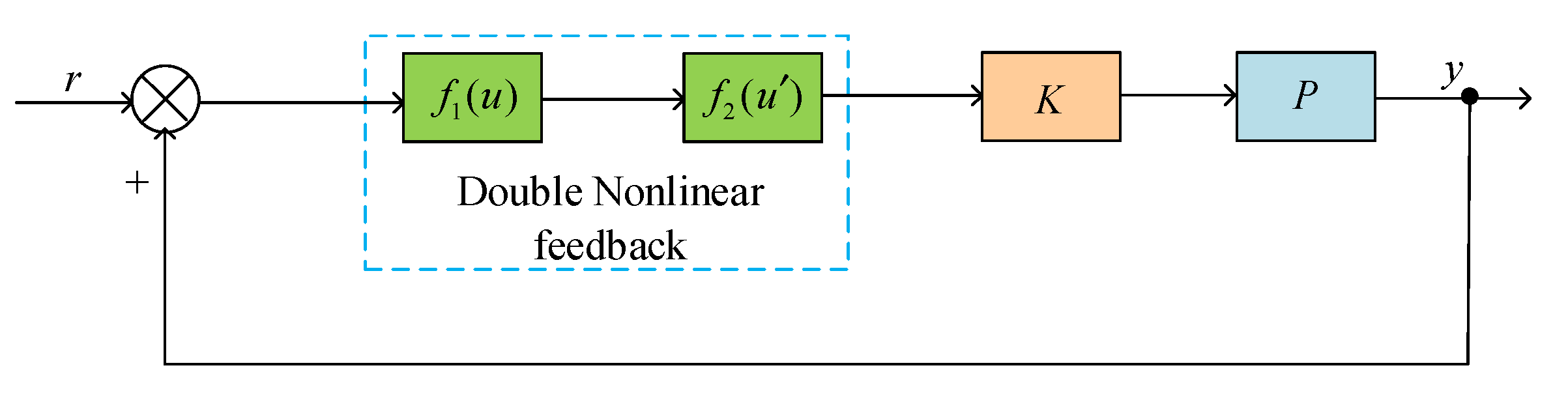
Due to the characteristics of large inertia and long time delays for super large ships, the traditional algorithms do not yield the necessary output for response control. Therefore, this paper moves beyond the concept of single nonlinear negative feedback and puts forward a dual nonlinear positive feedback control algorithm, which improves the capacity for pitching stabilization and further solves the problem of controller energy output dissipation.
(3)
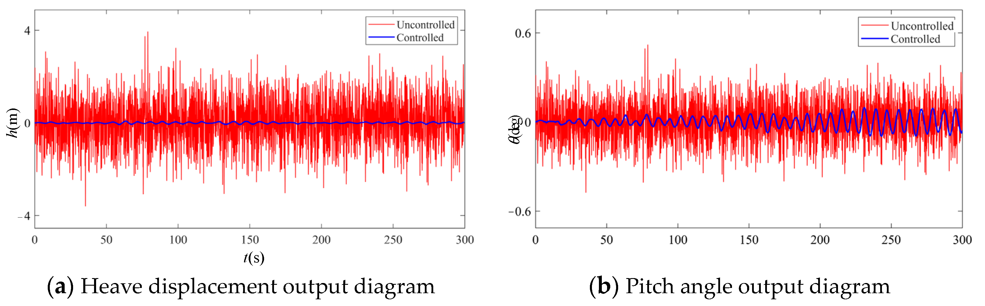
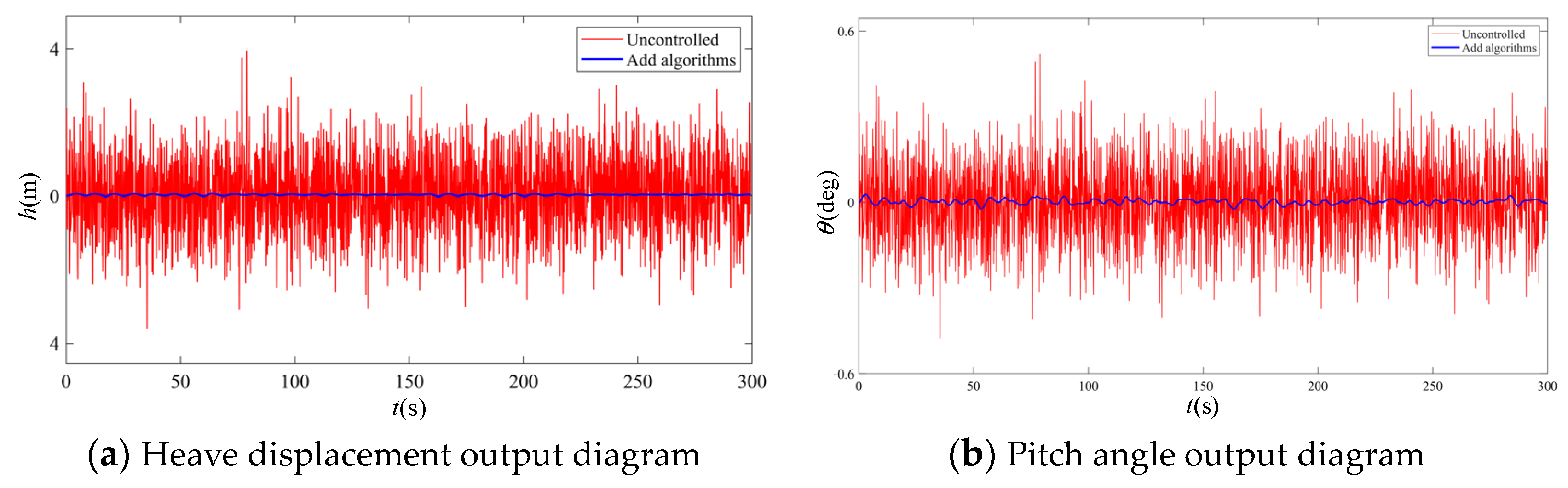
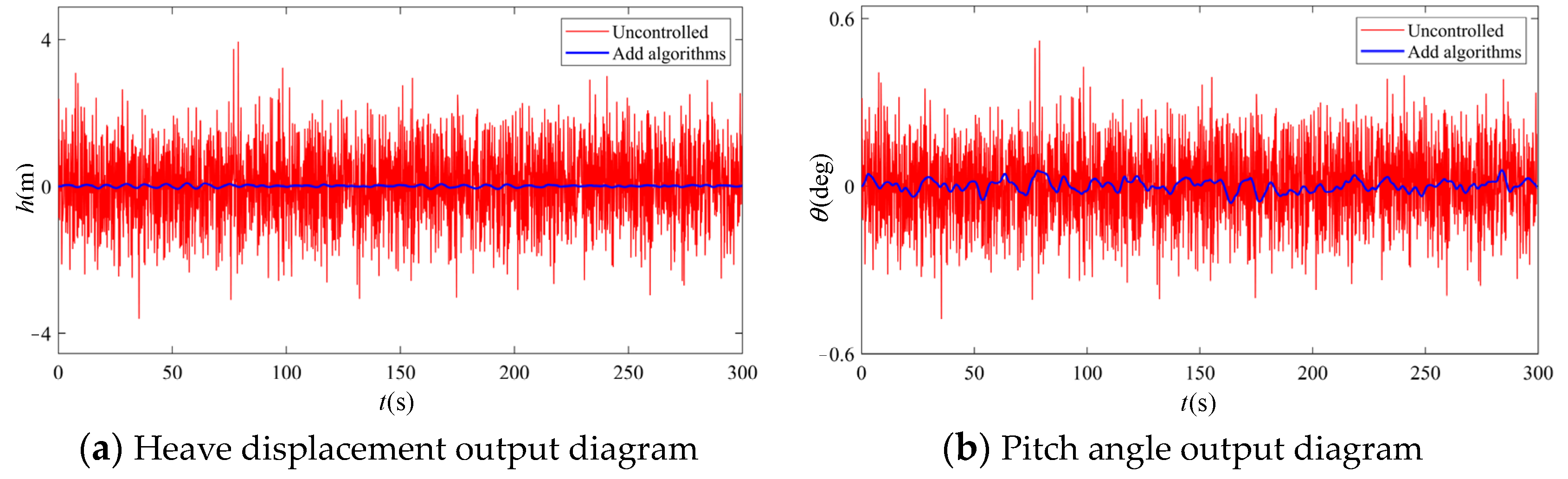
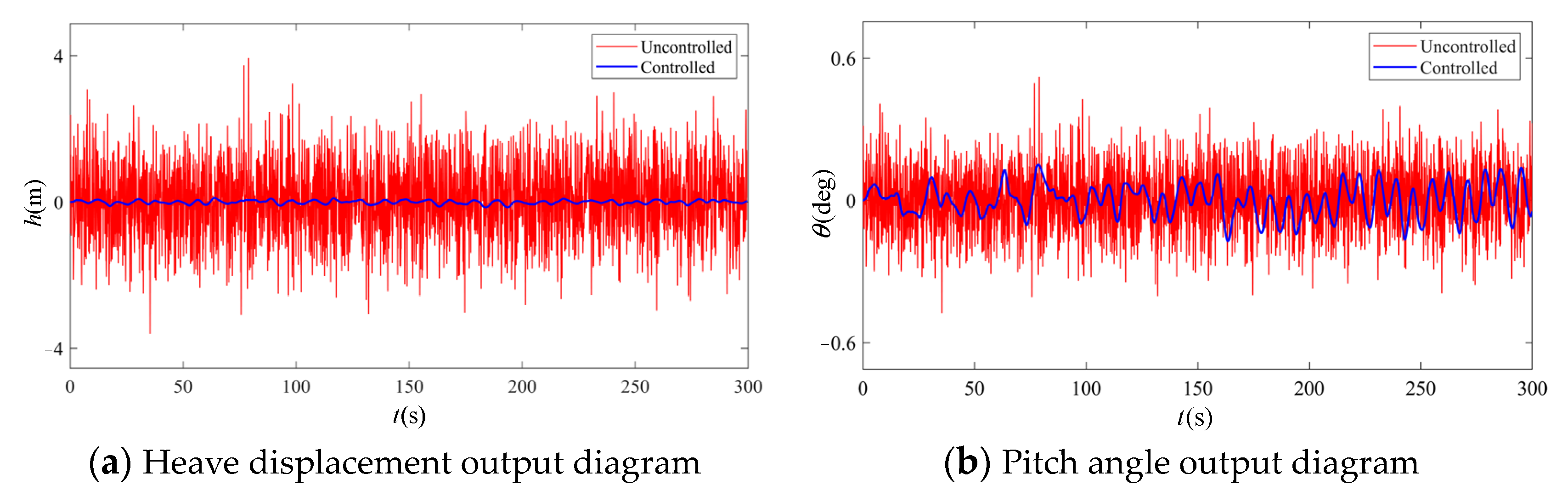
Utilizing the improved algorithm proposed in this paper, an experiment is carried out under level 6, 7 and 8 sea states for a super large ship, respectively. The results show that the improved controller can significantly reduce the ship’s pitch angle, heave displacement and longitudinal rocking frequency under different sea conditions. The improved algorithm can still achieve the expected pitching stabilization effect under rough sea conditions.
The other sections of this paper are organized as follows. Section 1 introduces the mathematical model of the motion of the super-large “KVLCC2” tanker; Section 2 describes the research methodology for the ship model; Section 3 proposes the design method for the simple robust controller; Section 3 introduces the dual nonlinear positive feedback control algorithm for improving the control system; Section 4 carries out simulation experiments to verify the pitching stabilization performance of the system; Section 5 provides the conclusions and outlook.

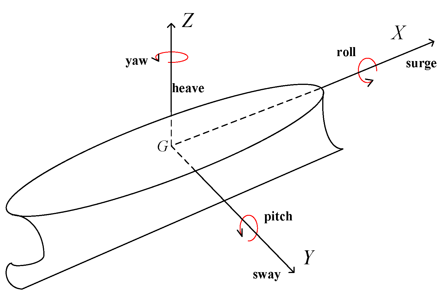
2. Mathematical Modeling of Ship Motion

Based on the theorem of Newtonian mechanics and the motion characteristics of ships sailing, we establish a mathematical model of the longitudinal motion of the super large oil tanker “KVLCC2” [15]. As shown in Figure 1, for the tanker’s motion’s coordinate system, we take the ship’s center of gravity G as the coordinate origin; the X-axis is in the center plane of the boat and parallel to the baseline, pointing towards the bow as positive; the Y-axis is perpendicular to the centerline face and points starboard as positive; and the Z-axis is mutually perpendicular to the horizontal plane and is positive upwards [16].
Analyzing the motion characteristics of a ship under the influence of waves, we can obtain a mathematical model of the ship’s longitudinal motion [17]:
( M + a z z ) z ¨ G + b z z z ˙ G + c z z z G + a z θ θ ¨ + b z θ θ ˙ + c z θ θ = F Z C cos ω e t + F Z S sin ω e t ( I θ θ + a θ θ ) θ ¨ + b θ θ θ ˙ + c θ θ θ + a θ z z ¨ G + b θ z z ˙ G + c θ z z G = M θ C cos ω e t + M θ S sin ω e t
In Equation (1), M represents the hull mass, a i j denotes the added mass or added mass moment of inertia and b i j is a damping coefficient associated with the linear or angular velocity of the motion. c i j is the resilience or moment coefficient of resilience; z ¨ G , z ˙ G , z G are the pendulum acceleration, velocity and amplitude, respectively; θ ¨ , θ ˙ , θ are the pitch motion angular acceleration, angular velocity and angle; F Z , M θ are the pendulum force and the longitudinal swing moment, respectively; and ω e is the wave encounter angle.
Making the following assumptions, the mathematical model of the ship is further simplified [18]:
(1)
The ship is treated as a rigid body, and its elastic deformation is ignored.
(2)
For the ship’s pitching stabilization control system, only two degrees of freedom of pitch and heave are considered.
Based on the above assumptions, we let the outputs be the pitch angle θ and the heave displacement h . Then, the transfer function-type mathematical model G is
G = G 11 G 12 G 21 G 22 = 1 G 1 a 11 a 12 a 21 a 22 .
Table 1 shows the ship parameters, and the parameters in Formula (2) can be obtained according to reference [19].

3. Modeling Research Methods

G 1 , a 11 and a 21 all have imaginary roots in the right half plane of the imaginary axis; thus, the system is easily divergent. According to the principle of root trajectory molding [20], the weight function of the root trajectory molding of the controlled plant is taken as
L ( s ) = L 11 0 0 L 22 .
We design the weight function coefficient matrix as λ .
λ = a 0 0 b
The above equation takes a = 100 , 000 , b = 200 , 000 . According to the principle of weight function molding [21], L 11 and L 22 in Equation (3) are taken as
L 11 ( s ) = 3 s + 4 s + 4 ,
L 22 ( s ) = 500 ( 0.5 s + 1 ) ( s + 0.1 ) s + 4 .
L 11 and L 22 contain a pole and two zeros. In summary, the generalized controlled plant is obtained as
P ( s ) = L ( s ) G ( s ) λ = L 11 G 11 L 11 G 12 L 22 G 21 L 22 G 22 a 0 0 b = a L 11 G 11 b L 11 G 12 a L 22 G 21 b L 22 G 22 .
Figure 2 shows a root trajectory diagram of the system after shaping by the weight function. Observing the root trajectory diagrams of P11, P12, P21 and P22, it can be seen that all of the roots are located in the left half plane of the imaginary axis. Therefore, the system is stable as a whole.

4. Design of the Robust Controller

Figure 3 illustrates the structure of the controller design, where noise is utilized to simulate wave disturbance (referred to as disturbance r ). The controller output is denoted as u , and the total system output is represented by y .
Since ships generate longitudinal rocking and heave motions under the action of waves during actual navigation, white noise is thus used to simulate the wave interference input r [22] (in the Simulink simulation experiment, the parameter is set to 0.1). We use a first-order closed-loop gain-shaping algorithm to design robust controllers. A closed-loop transfer function is formed with a simple integral link and a steady-state output value G to solve the problem of poor controller robustness.
When designing the controller, we let its diagonal element be 0.
K = C T 11 s 0 0 C T 22 s ,   C = 1 A ,   D = 1 B
The transfer function can be introduced through the above equation as
y r = K P 1 + K P = A C T 11 s 0 0 B D T 22 s / 1 + A C T 11 s 0 0 B D T 22 s = A C T 11 s 0 0 B D T 22 s T 11 s + A C T 11 s 0 0 T 22 s + B D T 22 s 1 .
Further simplification yields the following:
y r = 1 T 11 s + 1 0 0 1 T 22 s + 1 .
Equation (10) is the mathematical expression for the first-order closed-loop gain-shaping algorithm which belongs to a simple, robust control algorithm, by which we can obtain lower-order controllers.
This simple and robust controller also has the advantage of processing data blocks. Using global satellite navigation technology, real-time data from the ship are fed into the controller, which can respond quickly and make parameter adjustments.

5. The Double Nonlinear Positive Feedback Control System

5.1. Positive Feedback

Negative feedback is a common feedback mechanism in control systems which compares the output signal of the system with a desired reference signal. And using the difference as a correction of the input signal, it thus tunes the behavior of the system to reduce the difference and finally achieves the desired output of the system [23]. In contrast, this paper adopts the idea of positive feedback, which is an equivalent transformation of negative feedback into another form. The transfer function of the negative feedback closed-loop system can be expressed as K G / 1 + K G , and K denotes the control algorithm after adding nonlinear feedback. Positive feedback is a feedback signal in the loop from negative to positive, then multiplying the original negative feedback controller by −1 to become a positive feedback controller, namely K . Finally, we multiply by −1 for the system totality and transform it into mathematical formula form, as in Equation (11).
K G 1 + K G = 1 · K G 1 K G
A nonlinear positive feedback control system can achieve a faster control response by amplifying the excitation of the system, prompting the system to respond faster to external stimuli. Meanwhile, nonlinear positive feedback counteracts nonlinear effects. Thus, it can cope better with nonlinear challenges and achieve more stable control than negative feedback. Therefore, a nonlinear positive feedback control system is chosen in this paper to enhance the excitation effect and make the system more stable.

5.2. Dual Nonlinear Positive Feedback

Aiming at single nonlinear positive feedback control requires more intensive design and regulation in general and can easily cause system instability. Therefore, based on single nonlinear feedback, this paper selects double nonlinear positive feedback to adjust the output of the controller in time. With error feedback through a feed-forward system, nonlinear feedback replaces the original error feedback so as to improve the anti-pitching performance and energy-saving effect of the system. Meanwhile, a positive feedback control system enables better adaptation to changes in the external environment, effectively suppressing unstable behavior in the system, thereby improving the stability of the ship control system. Dual nonlinear positive feedback can accurately regulate the controller’s output in terms of the difference between the output and the input. Meanwhile, it avoids unnecessary energy iterations and reduces the energy consumption of the ship control system.
As shown in Figure 4, feed-forward is added in front of the controller, and the negative feedback of the system is changed into a positive feedback link. Equation (11) realizes the equivalent transformation of negative and positive feedback.
The dual nonlinear functions chosen in this paper are
f u 1 = cos   ( a · e ) f u 2 = tan   ( b · e ) .
In Equation (12), a = 0.1 ,   b = 0.25 . Equations (13) and (14) can be obtained according to the Taylor formula.
cos a e 1 a e 2 2 + a e 4 4 ! + o a e 4
tan   ( b e ) ( b e ) + b e 3 3 + 2 b e 5 15 + 17 b e 7 315 + o b e 7
Keeping Equation (13) within the second order,
cos   ( a · e ) = 1 ( a e ) 2 2 .
Keeping Equation (14) within the third order,
tan   ( b · e ) = b e + ( b e ) 3 3 .
By multiplying Equations (15) and (16), we can obtain the following:
f ( e ) = cos   ( a e ) · tan   ( b e ) = b e + ( b 3 3 a 2 b 2 ) e 3 .
The error e will directly affect the output of the whole control system; hence, the following two cases are analyzed theoretically, respectively.
  • When the error e is relatively low, f ( e ) b e = 0.25 e . We let ω = 0.25 < 1 and calculate the steady-state error e s s according to the final value theorem.
e s s = lim s 0 s X ( s ) = lim s 0 s 1 1 + K P ω 0 0 ω r s
Then, we see Equation (18) where K P is as follows:
K P = 1 T 11 s 0 0 1 T 22 s .
By substituting K P into Equation (18), we can obtain
e s s = lim s 0 r 1 + ω T 11 s 0 0 ω T 22 s = 0 .
From the results of Equation (20), it can be seen that the e s s output value is 0. Therefore, it can be judged that when the error is small, the dual nonlinear positive feedback control has no additional effect on the system.
  • When the value of the error e is large, f ( e ) b e = 0.25 e will not hold. The system was re-analyzed as follows.
Keeping Equation (13) within the fourth order,
cos a e = 1 ( a e ) 2 2 + ( a e ) 4 4 ! .
Keeping Equation (14) within the fifth order,
tan   ( b e ) = ( b e ) + b e 3 3 + 2 b e 5 15 .
Multiplying Equations (21) and (22) yields Equation (23).
f ( e ) = cos   ( a e ) · tan   ( b e ) = b e + ( b 3 3 a 2 b 2 ) e 3 + ( 2 b 5 15 a 2 b 3 6 + a 4 b 24 ) e 5 + a 4 b 3 72 a 2 b 5 15 e 7 + a 4 b 5 180 e 9
The output of a nonlinear link in the system under the action of a sinusoidal signal x ( t ) = A sin   ( ω t ) can be approximated using a first-order harmonic component. Based on the functional description method, the steady-state output y ( t ) is harmonically analyzed [24], and its first-order Fourier series expansion is obtained as Equation (24).
y ( t ) = A 0 + A 1 cos ( ω 0 t ) + B 1 sin ( ω 0 t )
where A 0 represents the DC component, and A 1 , B 1 represent the first-order harmonic components.
A 0 = 1 π 0 2 π y ( t ) d ( ω 0 t ) A 1 = 1 π 0 2 π y ( t ) cos ( ω 0 t ) d ( ω 0 t ) B 1 = 1 2 π 0 2 π y ( t ) sin ( ω 0 t ) d ( ω 0 t )
With the input e = A sin   ( ω 0 t ) , f e can be converted into Equation (26).
f ( t ) = b A sin   ( ω 0 t ) + ( b 3 3 a 2 b 2 ) A 3 sin 3   ( ω 0 t ) + ( 2 b 5 15 a 2 b 3 6 + a 4 b 24 ) A 5 sin 5   ( ω 0 t ) + a 4 b 3 72 a 2 b 5 15 A 7 sin 7   ( ω 0 t ) + a 4 b 5 180 A 9 sin 9   ( ω 0 t )
The descriptive function N A of the nonlinear system can be calculated by Equation (27).
N ( A ) = B 1 + j A 1 A
Through Equation (25), we obtain A 0 = 0 , A 1 = 0 .
B 1 = 2 π 0 π 2 b A sin ( ω 0 t ) + ( b 3 3 a 2 b 2 ) A 3 sin 3 ( ω 0 t ) + ( 2 b 5 15 a 2 b 3 6 + a 4 b 24 ) A 5 sin 5 ( ω 0 t ) + a 4 b 3 72 a 2 b 5 15 A 7 sin 7 ( ω 0 t ) + a 4 b 5 180 A 9 sin 9 ( ω 0 t ) · sin ( ω 0 t ) d ( ω 0 t ) = b 2 A + 3 8 ( b 3 3 a 2 b 2 ) A 3 + 5 16 ( 2 b 5 15 a 2 b 3 6 + a 4 b 24 ) A 5 + 35 128 a 4 b 3 72 a 2 b 5 15 A 7 + 7 a 4 b 5 5120 A 9
All powers of three or more can be ignored since the positive selection function value A is small. Therefore, it can be obtained that B 1 b 2 A .
N ( A ) = B 1 A = 0.125
The N A value of 0.125 is the constant value. As a result, even if the error increases significantly, the dual nonlinear positive feedback ensures that the system is stabilized, and there is no additional adverse effect.

6. The Simulation Experiment and Result Analysis

In practice, the double nonlinear positive feedback control algorithm is combined with a global navigation satellite system to further improve the ship’s pitch reduction performance. The navigation system is used to input the ship’s real-time position, speed, heading and other key parameters into the simple and robust controller designed in this paper. The controller adjusts the ship’s navigation and motion parameters according to the ship’s positioning data and motion state and then adjusts the ship’s propulsion system and roll stabilizer to achieve the purpose of reducing its pitch. This paper assumes that the ship’s real-time position, speed and heading are known and then conducts the following experiments.

6.1. Modeling of External Interference

Waves are the main cause of longitudinal rocking during ship navigation. This paper uses white noise to drive a second-order transfer function to simulate wave disturbances, which makes it simple, convenient and easy to verify the controller’s performance. The principle is that the ITTC one-parameter spectrum is linearly approximated as y s = h s · ω s , with ω s representing a zero-mean Gaussian white noise process [25] and the power spectrum taken to be 1.0. h s represents the second-order wave transfer function, as shown in Equation (30).
h s = 2 ξ ω n σ ω s s 2 + 2 ξ ω n s + ω n 2
where σ ω = 0.0185 T ω h 1 / 3 refers to the constant of the wave’s intensity; ξ is the damping factor; ω n = 4.85 / T ω refers to the wave’s frequency; and T ω is the wave’s period. This paper simulates level 6, 7 and 8 sea states, and the second-order wave transfer function for different wind conditions can be calculated according to Equation (31). Then, we add it to the control system to check the performance of the controller in reducing longitudinal sway under changing sea conditions. Table 2 shows the second-order wave transfer function for different wind levels.

6.2. Verification of Dual Nonlinear Positive Feedback

The controller will have a certain pure lag link in the realization of the pitching stabilization process. This pure lag link may lead to a slower response from the system, which may influence the effect of the control. To verify the dual nonlinear positive feedback control algorithm, a pure lag link e τ s is added to the control system, and the ingestion model system is shown in Figure 5.
A time lag constant is added to the control system, and simulation experiments are carried out under level 6, 7 and 8 sea states, respectively. The time lag constant is set to τ = 0.25 , and the time is set to 300 s. We let h m be the maximum heave displacement, θ m be the maximum pitch angle and e 1 , e 2 be the energy metrics for the total heave displacement and total pitch angle, respectively. The calculation is shown in Equations (31) and (32).
e 1 = t = 1 n h i h ¯ 2 n 1
e 2 = t = 1 n θ i θ ¯ 2 n 1
From Figure 6, Figure 7, Figure 8, Figure 9, Figure 10 and Figure 11, it can be seen that adding the dual nonlinear positive feedback control algorithm to the control system significantly improves the system’s pitching stabilization performance. Table 3 shows the performance parameters under changing sea conditions. By analyzing Table 3, it can be concluded that the dual nonlinear positive feedback control system increases the maximum displacement output value by 16% and the maximum pitch angle output value by 70% and improves e 1 , e 2 by 39% and 80% compared with linear feedback control under level 6 sea conditions. Its pitching stabilization performance and energy-saving effect are significantly enhanced. Comparing Figure 8 and Figure 9, it can be seen that dual nonlinear positive feedback control still reduces the ship model’s pitch angle and the frequency of the ship’s longitudinal rocking under level 7 sea conditions. The maximum displacement output value increased by 44% and the maximum pitch angle output value by 40% and e 1 , e 2 improved by 18% and 55% compared with linear feedback control under level 7 sea conditions. Analyzing Figure 10 shows that the pitch angle of the ship model increases significantly and dramatically under level 8 sea conditions. By adding a dual linear positive feedback control algorithm to the system, the violent longitudinal rocking is improved. According to the above comparison, the dual nonlinear positive feedback control algorithm proposed in this paper not only achieves the expected pitching stabilization effect under a level 6 sea state but also in level 7 and 8 sea conditions; it can significantly reduce the output values of the maximum heave displacement and the maximum pitch angle and the frequency of longitudinal rocking.

7. Conclusions

This paper takes the super large oil tanker “KVLCC2” as the controlled plant, using the weighting matrix to make its transfer function’s mathematical model stable and utilizing the root trajectory shaping method to verify the stability of the model. The improved closed-loop gain-shaping algorithm is used to design a simple robust controller. And a dual nonlinear positive feedback algorithm is added to the control system. It is proven according to mathematical derivation that both large and small errors resulting from the introduction of feedback will not have an additional effect on the steady state of the system. Introducing the second-order wave transfer function and a perturbation link for level 6, 7 and 8 sea states, the results show that the dual nonlinear positive feedback control algorithm is effective in pitching stabilization in rough sea conditions and further reduces the controller’s energy output, solving the problem of excessive control energy in the existing algorithms. The proposed algorithm is subversive and innovative, providing technical support for domestic and international super large ships to navigate under severe sea conditions. Meanwhile, it plays a role in advancing the development of super large ships. In the future, the algorithm proposed in this paper will be added to a real ship, and all the parameters will be input into the double nonlinear positive feedback control system by the navigation system to further verify the applicability and reliability of the algorithm proposed in this paper.

Author Contributions

Conceptualization, C.S.; methodology, C.S.; software, C.S.; validation, C.S. and J.S.; formal analysis, Q.Q.; investigation, Q.Q.; resources, J.S. and C.S.; data curation, Q.Q.; writing—original draft preparation, C.S. and Q.Q.; writing—review and editing, C.S. and Q.Q.; visualization, C.S.; supervision, J.S.; project administration, J.S.; funding acquisition, J.S. All authors have read and agreed to the published version of the manuscript.

Funding

This study received funding from Liaoning Provincial Department of Education’s Basic Scientific Research Project for Colleges and Universities in 2023 (JYTQN2023131) and Liaoning Province Department of Science and Technology Artificial Intelligence Field Applied Basic Research Program (600024003).

Institutional Review Board Statement

Not applicable.

Informed Consent Statement

Not applicable.

Data Availability Statement

If you need to obtain the experimental information and data presented in the paper, please contact the author.

Conflicts of Interest

The authors declare no conflicts of interest.

References

  1. Zhang, G.; Zhang, X. A novel DVS guidance principle and robust adaptive path-following control for underactuated ships using low frequency gain-learning. ISA Trans. 2015, 56, 75–85. [Google Scholar] [CrossRef] [PubMed]
  2. Li, J.; Zhang, G.; Zhang, W.; Shan, Q.; Zhang, W. Cooperative path following control of USV-UAVs considering low design complexity and command transmission requirements. IEEE Trans. Intell. Veh. 2024, 9, 714–724. [Google Scholar] [CrossRef]
  3. Chandrasekaran, S.; Sharma, R.; Selvakumar, N.M. Dynamic analysis of drillship under extreme metocean hurricane condition in ultra-deep water. J. Mar. Sci. Technol. 2023, 28, 784–803. [Google Scholar] [CrossRef]
  4. Ni, J.; Huang, Y. Distribution and positioning design of ship active anti-roll fins. Ship Sci. Technol. 2022, 44, 44–47. [Google Scholar]
  5. Zhang, S.; Zhao, P.; Gui, M.; Liang, L. Wavelet neural network-based half-period predictive roll-reduction control using a fin stabilizer at zero speed. J. Mar. Sci. Eng. 2023, 11, 2025. [Google Scholar] [CrossRef]
  6. Li, W.; Huang, H.; Miao, G. Study on the effect of anti-pitching rudder on ship pitch reduction. J. Hydrodyn. 2008, 23, 585–591. [Google Scholar]
  7. Zhang, G.; Li, J.; Jin, X.; Liu, C. Robust adaptive neural control for wing sail assisted vehicle via the multiport event-triggered approach. IEEE Trans. Cybern. 2022, 52, 12916–12928. [Google Scholar] [CrossRef]
  8. Li, W.; Zhang, J.; Xu, W. High-speed multihull anti-pitching control based on heave velocity and pitch angular velocity estimation. ISA Trans. 2024, 146, 380–391. [Google Scholar] [CrossRef] [PubMed]
  9. Xu, W.; Zhang, J.; Zhong, M. A sliding mode predictive anti-pitching control for a high-speed multihull. Ocean Eng. 2023, 285, 115466. [Google Scholar] [CrossRef]
  10. Zhang, J.; Liu, Z.; Dai, X.; Li, G. Robust decoupled anti-pitching control of a high-speed multihull. J. Mar. Sci. Technol. 2021, 26, 1112–1125. [Google Scholar] [CrossRef]
  11. Song, C.Y.; Zhang, X.K.; Zhang, G.Q. Attitude prediction of ship coupled heave–pitch motions using nonlinear innovation via full-scale test data. Ocean Eng. 2022, 264, 112524. [Google Scholar] [CrossRef]
  12. Chen, C.; Song, W. Analysis and synchronization control of a class of nonlinear feedback chaotic systems. Ship Control Decis. 2002, 17, 49–52. [Google Scholar]
  13. Zhang, X.; Cao, T. Reduced longitudinal rocking control of ships based on nonlinear feedback with arctangent function. J. Guangdong Ocean Univ. 2022, 42, 30–37. [Google Scholar]
  14. Cao, T.; Zhang, X. Nonlinear decoration control based on perturbation of ship longitudinal motion model. Appl. Ocean Res. 2023, 130, 103412. [Google Scholar] [CrossRef]
  15. Song, C.; Zhang, X.; Zhang, G. Nonlinear identification for 4-DOF ship maneuvering modeling via full-scale trial data. IEEE Trans. Ind. Electron. 2021, 69, 1829–1835. [Google Scholar] [CrossRef]
  16. Song, C.; Zhang, X.; Zhang, G. Nonlinear innovation-based maneuverability prediction for marine vehicles using an improved forgetting mechanism. J. Mar. Sci. Eng. 2022, 10, 1210. [Google Scholar] [CrossRef]
  17. Wu, H. Real-time simulation of ship rocking motion based on Unity3D. Master’s Thesis, Dalian Maritime University, Dalian, China, 2020. [Google Scholar]
  18. Cao, T.; Zhang, X. Nonlinear feedback control of ship longitudinal motion multi-input multi-output unstable system. J. Shanghai Jiao Tong Univ. 2023, 57, 972. [Google Scholar]
  19. Zhang, X.; Zhang, G. Nonlinear Feedback Theory and Its Application in Ship Motion Control; Dalian Maritime University Press: Dalian, China, 2020. [Google Scholar]
  20. Durutoye, N.; Ogunbiyi, O. Automatic generation of root locus plots for linear time invariant systems. Niger. J. Technol. 2016, 36, 155–162. [Google Scholar] [CrossRef]
  21. Wu, G.C.; Niyazi Çankaya, M.; Banerjee, S. Fractional q-deformed chaotic maps: A weight function approach. Chaos 2020, 30, 121106. [Google Scholar] [CrossRef] [PubMed]
  22. Li, J.; Zhang, G.; Zhang, X.; Zhang, W. Integrating dynamic event-triggered and sensor-tolerant control: Application to USV-UAVs cooperative formation system for maritime parallel search. IEEE Trans. Intell. Transp. Syst. 2024, 25, 3986–3998. [Google Scholar] [CrossRef]
  23. Guan, K.; Zhang, X. Negative feedback control algorithm for ship nonlinear roll motion. J. Shanghai Marit. Univ. 2016, 37, 58–62. [Google Scholar]
  24. Hu, S. Principles of Automatic Control, 4th ed.; Science Press: Beijing, China, 2021. [Google Scholar]
  25. Song, C.; Guo, T.; Sui, J.; Zhang, X. Dynamic Positioning Control of Large Ships in Rough Sea Based on an Improved Closed-Loop Gain Shaping Algorithm. J. Mar. Sci. Eng. 2024, 12, 351. [Google Scholar] [CrossRef]
Figure 1. Ship motion coordinate system.
Jmse 12 01657 g001
Figure 2. Stabilizing root trajectory after forming.
Jmse 12 01657 g002
Figure 3. Simple robust controller design framework.
Jmse 12 01657 g003
Figure 4. Structure of the feed-forward control system.
Jmse 12 01657 g004
Figure 5. Perturbation system.
Jmse 12 01657 g005
Figure 6. Linear feedback under level 6 sea conditions.
Jmse 12 01657 g006
Figure 7. Nonlinear positive feedback under level 6 sea conditions.
Jmse 12 01657 g007
Figure 8. Linear feedback under level 7 sea conditions.
Jmse 12 01657 g008
Figure 9. Nonlinear positive feedback under level 7 sea conditions.
Jmse 12 01657 g009
Figure 10. Linear feedback under level 8 sea conditions.
Jmse 12 01657 g010
Figure 11. Nonlinear positive feedback under level 8 sea conditions.
Jmse 12 01657 g011
Table 1. Basic parameters of oil tanker “KVLCC2”.
ItemSignValue
Length between perpendiculars L m 320.0
Breadth B m 58.0
Longitudinal center of gravity X C ( m ) 11.2
Rudder area A δ m 2 112.26
Speed (max) V kn 15.8
Displacement [ m 3 ] 312,600.0
Draft (full load) D m 20.8
Block coefficient C b 0.81
Table 2. Second-order wave transfer function for different wind levels.
Wind LevelCalculation of the Wind Level (kn)Meaningful Wave Height (m)Wave Period (s)Second-Order Wave Transfer Function
No. 624.53.9627.0 0.5927 s s 2 + 0.4157 s + 0.4801
No. 730.57.018.7 1.2542 s s 2 + 0.446 s + 0.3108
No. 83711.2810.5 2.2964 s s 2 + 0.4619 s + 0.2134
Table 3. Performance parameters under changing sea conditions.
Wind LevelLinear FeedbackDual Nonlinear Positive Feedback
h m θ m e 1 e 2 h m θ m e 1 e 2
No.60.0810.0960.0280.0400.0680.0290.0170.008
No.70.0910.1130.0330.0470.0870.0580.0270.021
No.80.1210.1510.0480.0660.1200.1360.0470.047
Disclaimer/Publisher’s Note: The statements, opinions and data contained in all publications are solely those of the individual author(s) and contributor(s) and not of MDPI and/or the editor(s). MDPI and/or the editor(s) disclaim responsibility for any injury to people or property resulting from any ideas, methods, instructions or products referred to in the content.

