Article

Application of Self-Polishing Copolymer and Tin-Free Nanotechnology Paint for Ships

1
Department of Mold and Die Engineering, National Kaohsiung University of Science and Technology, Kaohsiung 807618, Taiwan
2
Ship and Ocean Industries R&D Center, Taipei 251401, Taiwan
*
Author to whom correspondence should be addressed.
J. Mar. Sci. Eng. 2024, 12(9), 1662; https://doi.org/10.3390/jmse12091662
Submission received: 18 August 2024 / Revised: 11 September 2024 / Accepted: 12 September 2024 / Published: 16 September 2024
(This article belongs to the Section Ocean Engineering)

Abstract

:
During a ship’s voyage, it is difficult to maintain its hull, and prolonged exposure to seawater can lead to the attachment of marine organisms, which can negatively impact the ship’s speed. The original self-polishing copolymer was a tributyltin-containing paint used for applying two layers of protective coating onto a ship’s bottom plate. According to International Maritime Organization (abbreviated as IMO) regulations, users are no longer allowed to use paints containing tributyltin. Therefore, manufacturers have developed a tributyltin-free paint, known as tin-free nanotechnology paint, which can be used as a replacement for the base coat on ship bottom plates. This study involves the use of a self-polishing copolymer spray and tin-free nanotechnology paint. A model coated with these two types of paint will be observed underwater to study the growth of marine organisms. Additionally, fuel consumption will be analyzed through underwater inspections and sea trials. Based on the experimental data, it is known that tin-free nanotechnology paint can significantly reduce the need for repairs in factories and greatly decrease maintenance costs when compared to self-polishing copolymers.

1. Introduction

In recent years, there has been a global push for marine environmental protection, with a growing emphasis on preserving marine and offshore ecosystems. Biofouling refers to the attachment of marine organisms, such as algae, barnacles, and other microorganisms, to the surfaces of ship hulls or other underwater structures, forming a biological layer. This phenomenon is undesirable because it increases the drag on the vessel, thereby reducing speed, increasing fuel consumption, and accelerating hull corrosion [1,2]. Additionally, biofouling can affect the functionality and lifespan of underwater structures.
The most common antifouling measures include the use of antifouling paints and regular cleaning. Antifouling paint is a type of coating that contains toxic substances that can inhibit or kill the organisms that attach to the surface [3]. Its advantage lies in its long-lasting effectiveness, reducing biofouling and, consequently, maintenance costs. However, the drawback is that some antifouling paints contain harmful chemicals that can negatively impact the environment. Another method is regular cleaning, which involves the use of high-pressure water jets or divers to remove fouling from the surface. This method does not use chemicals, making it environmentally friendly, but its disadvantage is that it is time-consuming, labor-intensive, and requires regular maintenance to prevent the accumulation of biofouling.
The “International Convention on the Control of Harmful Anti-fouling Systems on Ships” was created to prohibit ships from using antifouling paints that are highly toxic to marine organisms. This measure aims to ensure the protection of marine life. The hull’s paint film is first coated with an anti-rust primer on the metal surface, followed by a layer of self-polishing antifouling paint. This paint has the characteristic of emitting toxic substances. When the ship is coated with this paint, it will release toxic substances. It is not easy for marine organisms to attach to the bottom of a ship. If the ship undergoes regular docking for sandblasting and the removal of marine organisms, the paint film and coating may get mixed with the sandblasting material, leading to incidents of marine ecological pollution or exacerbating the issue of industrial waste disposal.
This study will utilize self-polishing copolymer and tin-free nanotechnology paint, which contains tributyltin, to coat two different layers on the bottom plate of a ship. The study will also involve conducting underwater inspections and analyzing fuel consumption while the ship is at sea. This research also greatly improves the maneuverability of the ship, shortens the period required for docking to remove marine organisms, reduces the maintenance cost of replacing the hull plate, and increases the durability of the ship’s mobile service.

2. Literature Review

Research has shown that antifouling paint can protect the hull from biofouling-induced corrosion. When a ship is coated with antifouling paint, the self-polishing copolymer TBT paint gradually dissolves as it reacts with water on the surface, slowly releasing biocides [4,5,6], with a lifespan of up to 60 months. Non-stick coatings are non-toxic and smooth, preventing pollutant adhesion, making them an ideal choice for high-speed vessels exceeding 30 knots [7].
The International Maritime Organization (IMO) [8] has highlighted that biological fouling is influenced by factors such as ship loading, operating zones, antifouling paint effectiveness, and environmental conditions. Ships in constant motion accumulate less marine growth than those that are stationary for extended periods, which can lead to fouling, reduced speed, and increased fuel consumption. Hull cathodic protection is more effective when the ship is moving. Self-polishing copolymers containing tributyltin (TBT) are highly toxic to marine life, and IMO regulations prohibit fouling management coatings from containing TBT compounds.
The effects of biofouling on ship speed and fuel consumption are significant. The authors of [9,10] noted that hull roughness affects antifouling coatings’ effectiveness, emphasizing its importance. In 2014, Yigit et al. [11,12] found that increased hull roughness leads to higher frictional resistance, greater fuel consumption, and increased CO2 emissions, with a verified CFD model predicting these effects. In 2016, Monty et al. [13] demonstrated that light calcareous tubeworm fouling on an FFG-7 frigate model increased total resistance by 23%, while a similarly fouled VLCC saw a 34% increase in drag.
In 2017, Yigit et al. [14] developed a roughness function model to predict the increase in effective power due to barnacle fouling on a full-scale KCS hull, finding that light slime fouling could raise effective power by 18.1% at 24 knots, while heavy slime could increase it by 38%. Towing tests with synthetic barnacles were conducted to validate these predictions, analyzing the effects of varying barnacle heights and coverage on resistance and power efficiency. In 2019, Yigit et al. [15] further created practical resistance diagrams to predict increases in frictional resistance and effective power under various coating and fouling conditions.

3. Experimental Methods and Records

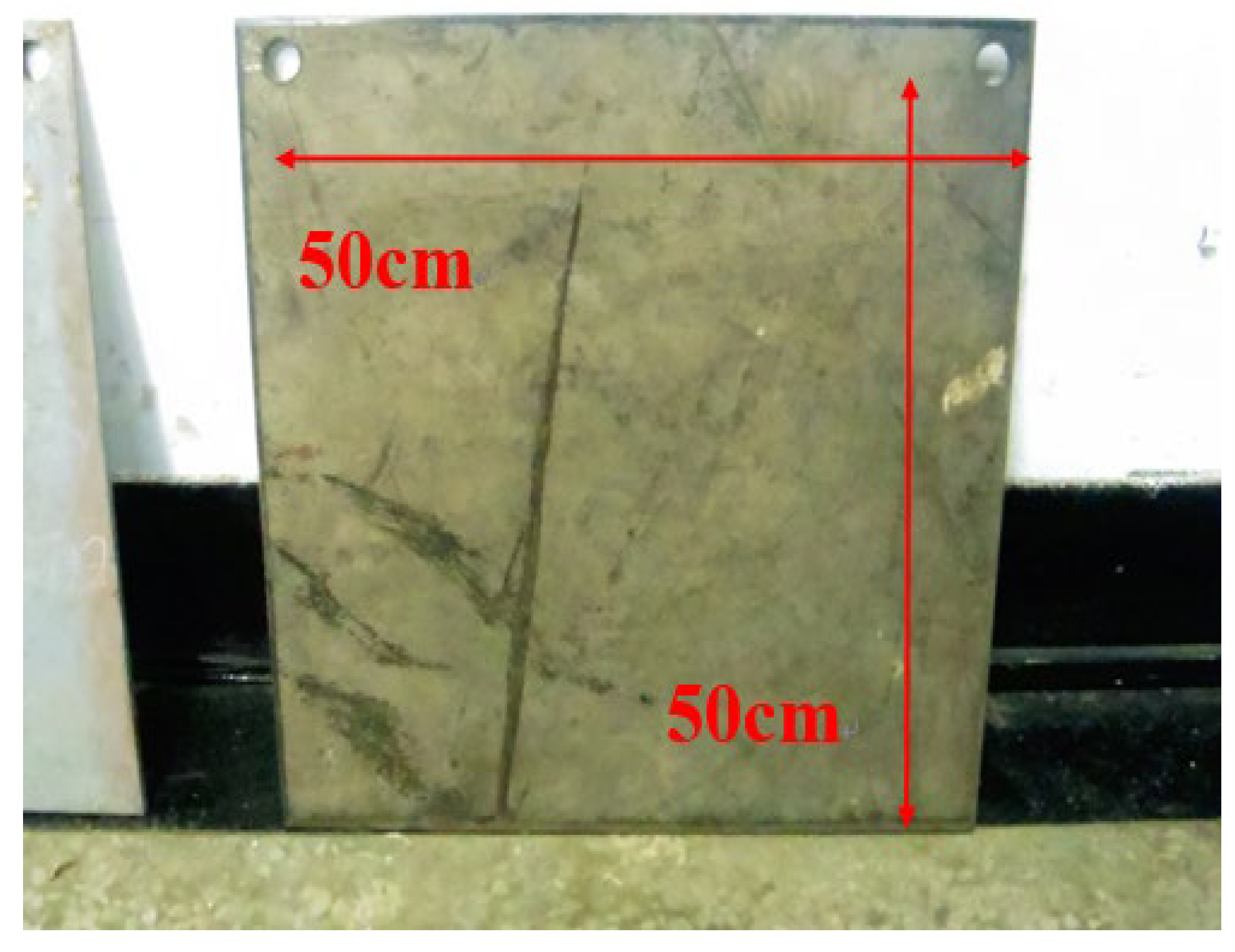
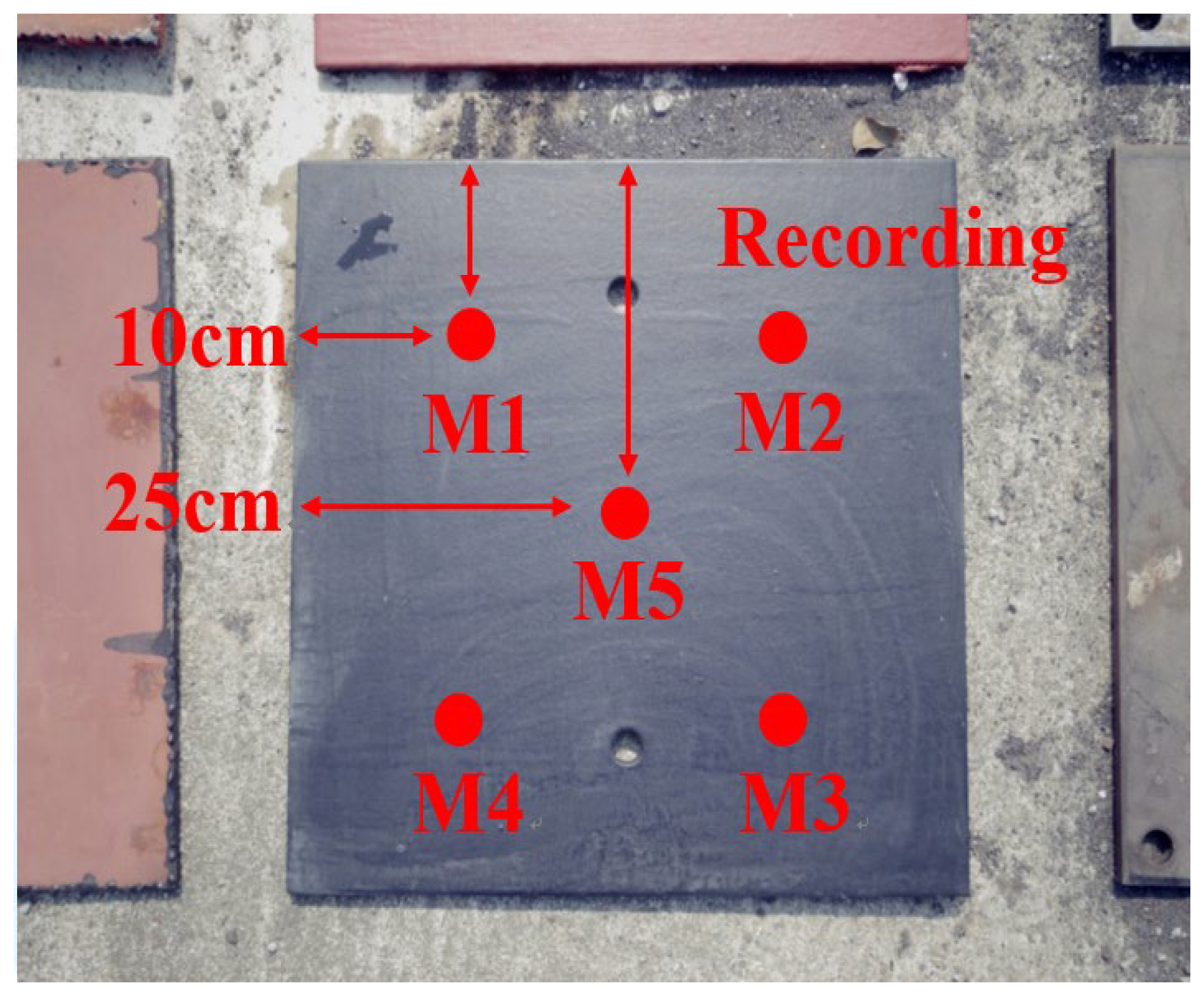
3.1. Paint Film Spraying Experiment

According to the U.S. Navy Technical Manual MIL-PRF-24647D [16], the paint used on ship hulls must undergo testing. The paints covered by this specification are classified by type, class, grade, and application. Table 1 provides information regarding the classifications of ship hull anticorrosive and antifouling paint systems.
Conducting these tests is crucial to ensure that the hull paint meets the corrosion resistance and fouling prevention standards set by the Navy. These standards are crucial for maintaining the structural integrity of the ship and ensuring its long-term performance in challenging marine environments.
The selection of ship hull anticorrosive and antifouling paint systems must be carefully considered, taking into account the type, class, grade, and intended application of the ship, as well as its operating environment. By adhering to these standards and conducting rigorous testing, the Navy can ensure the safety and effectiveness of its fleet.
Notes:
The types of ship hull anticorrosive and antifouling paint systems are as follows:
  • Type I—Paint systems with topcoats that contain biocide(s), other than copper, which ablate or self-polish.
  • Type II—Paint systems with topcoats that contain biocide(s) (copper or other biocide not cited in Type I) that ablate or self-polish.
  • Type III—Paint systems with topcoats that are foul-released and contain no biocide.
  • Type IV—Paint systems with topcoats that contain biocide(s) (copper or other) that do not ablate or self-polish.
The classes of ship hull anticorrosive and antifouling paint systems are as follows:
  • Class 1—Paint systems for use on rigid, fiberglass, wood, or metallic substrates, other than aluminum.
  • Class 2—Paint systems for use on aluminum substrates.
  • Class 3—Paint systems for use on elastomeric substrates.
The applications of ship hull anticorrosive and antifouling paint systems are as follows:
  • App1—Paint systems for use on the underwater hull, with a service life of three years.
  • App2—Paint systems for use on the underwater hull, with a service life of seven years.
  • App3—Paint systems for use on the underwater hull, with a service life of twelve years.
  • App4—Paint systems for use on high-speed vessels with a service life of a minimum of two years.
For this research, four groups of models were constructed using EH36 and HY80 steel plates. Each model was cut to a size of 50 × 50 cm, as illustrated in Figure 1. The models were subjected to various surface treatments and antifouling paint coatings. The surface treatments followed the SP 10 standard of the Society for Protective Coatings (SSPC) [17], which is described below:
  • Models 1 and 2 utilize surface treatment and a self-polishing copolymer spray as a type of antifouling paint.
  • Models 3 and 4 involve surface treatment and the spraying of tin-free nanotechnology paint, which is another type of antifouling paint, as shown in Table 2.
Description: SSPC-SP 10 requires the removal of at least 95% of black scale, rust, and other foreign matter from the steel surface through sandblasting.
Each steel plate was submerged underwater at the pier for testing. This study aims to assess the efficacy of various surface treatments and antifouling paint coatings in preventing fouling on steel plates utilized in marine environments.
By comparing the performance of each model, researchers can determine the most effective surface treatment and antifouling paint coating for preventing fouling on steel plates. This information can be useful in the design and maintenance of ships and other marine structures, ensuring their longevity and efficient operation in harsh marine environments.

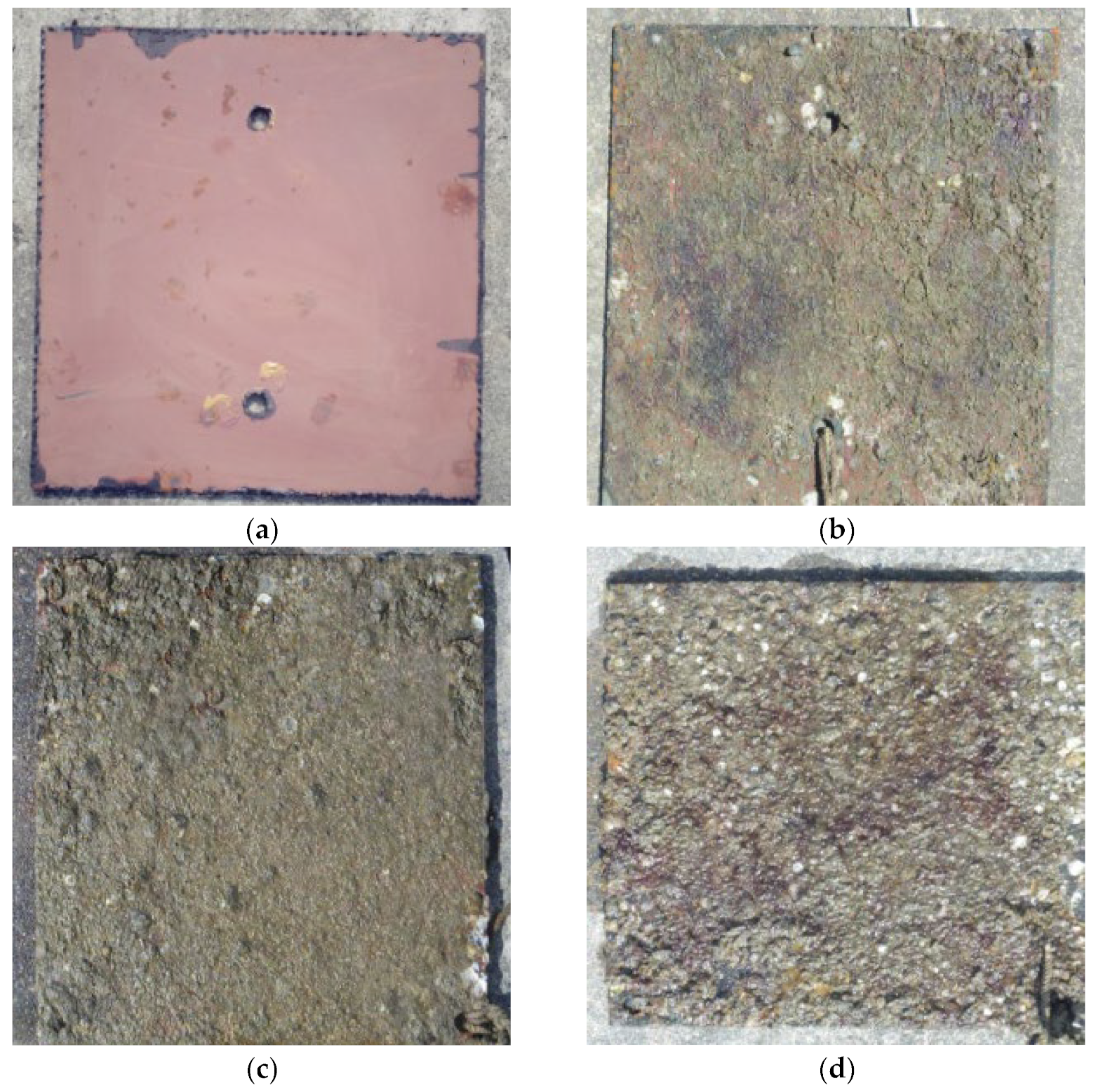
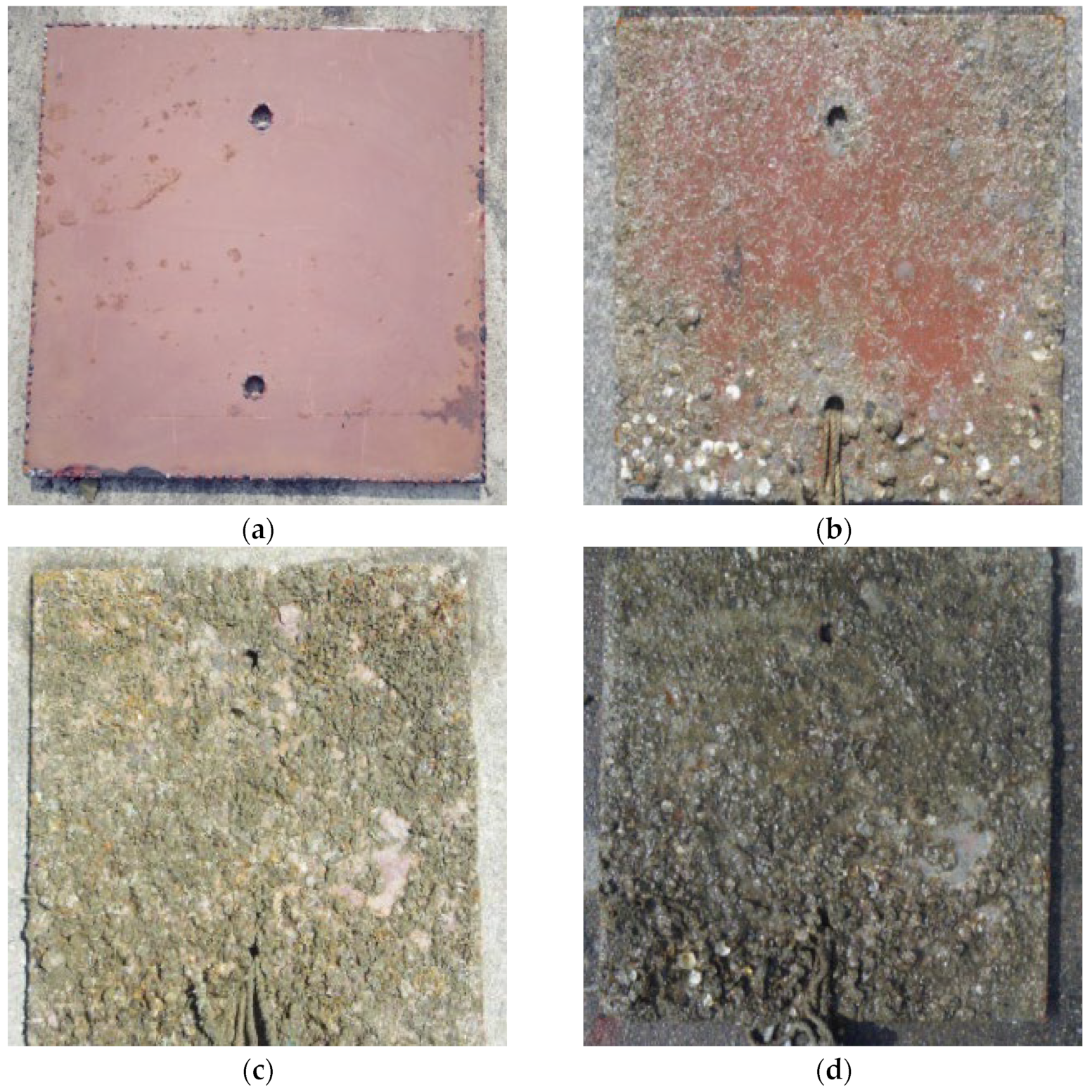
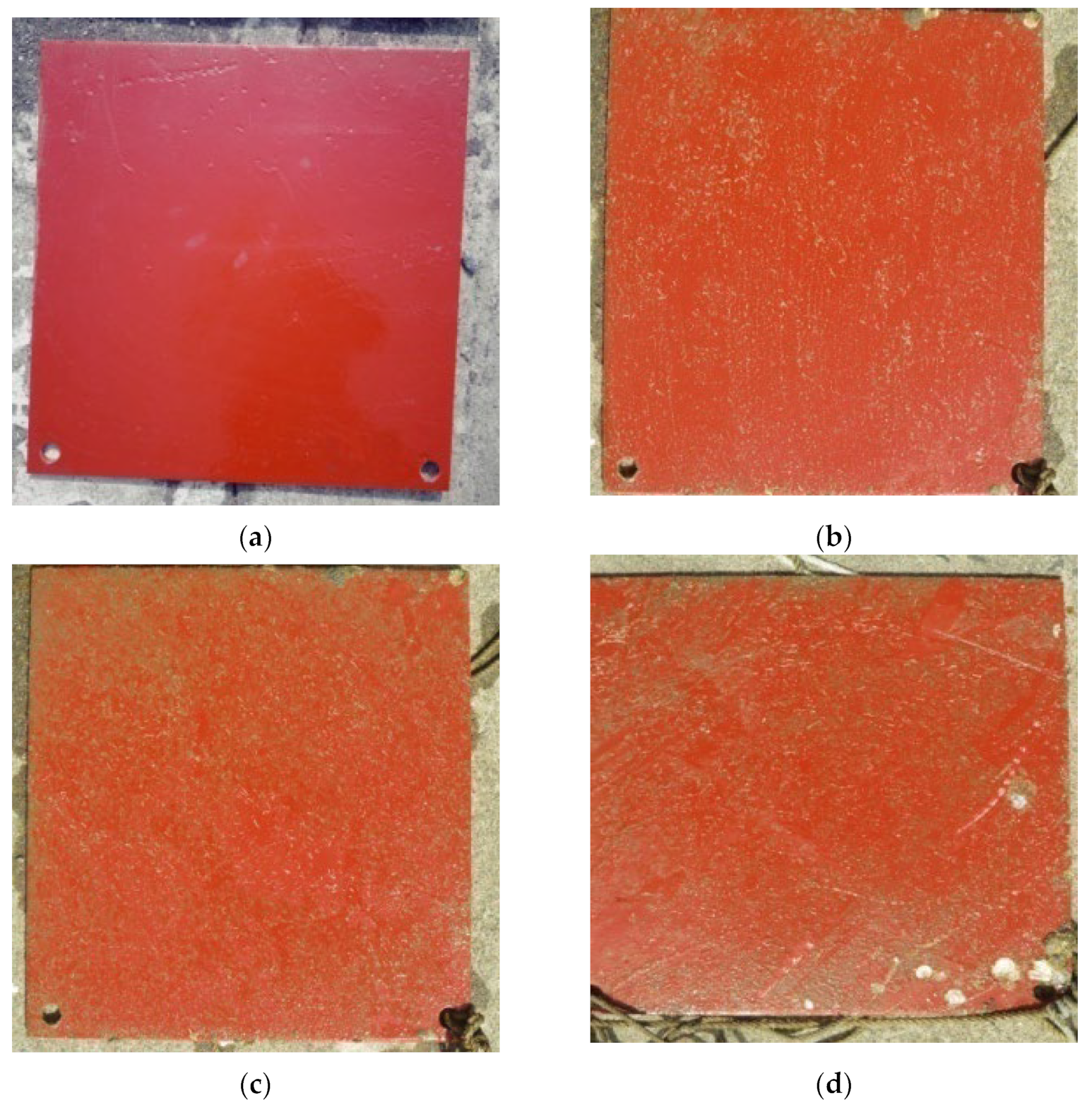
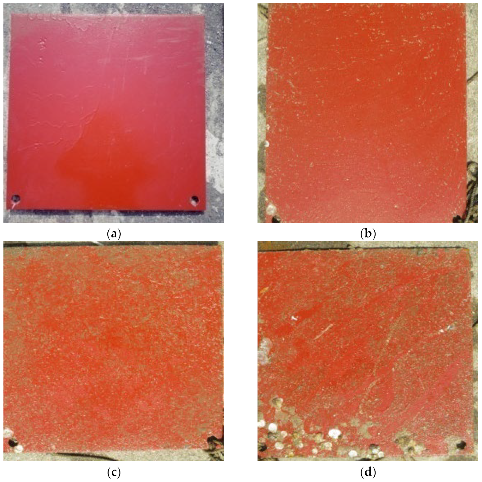
3.2. Hull Spray Paint Film Test

To evaluate the effectiveness of self-polishing copolymer and tin-free nanotechnology coatings in preventing biological fouling on ship hulls, two identical ships with EH36 steel hulls were selected. Below the waterline, each hull was coated with two layers of Primer2 and two layers of intermediate coat. One ship received two layers of the self-polishing copolymer as the topcoat, while the other received two layers of tin-free nanotechnology paint as the topcoat. After completing the coating applications simultaneously, a three-month trial was conducted. The hulls, seabed doors, shafts, propellers, rudder plates, and other parts were coated with either self-polishing copolymer or tin-free nanotechnology paint. After the trial period, underwater inspections were conducted on these parts to observe the growth status of biofouling, as shown in Figure 2. These inspections were conducted to assess the effectiveness of the coatings in preventing biofouling and their potential as environmentally friendly substitutes for conventional antifouling coatings.

3.3. Ships’ Sea Trial Test

Two ships were coated with self-polishing copolymer and tin-free nanotechnology paint that did not contain tributyltin. The ships were tested at six different speeds in a predetermined location within the designated water area, as shown in Figure 3. The output speed and hourly fuel consumption of the main engine were measured and recorded for each speed, and a comparative analysis was conducted.

4. Results and Discussion

4.1. Research Model Construction Analysis

This study examined the attachment and growth of marine organisms on steel plates using the U.S. Navy Technical Manual MIL-PRF-24647D to ensure technical accuracy. Four groups of models were created for experimentation and were placed on a pier for underwater observation. The thickness of the marine organisms attached to the steel plate was measured at five different recording points (M1 to M5) using a vernier caliper over a period of 15 weeks, as shown in Figure 4.
In this study, the models were submerged in a three-meter-deep underwater experiment at Zuoying Harbor in Taiwan. The experiment was conducted for a duration of 15 weeks. During the first four weeks, the daytime seawater temperature was observed to be 25.5 °C. From the fifth to eighth weeks, the temperature of the seawater increased to 27.2 °C. During the ninth to twelfth weeks, the temperature of the seawater increased to 27.7 °C. During the thirteenth to fifteenth weeks, the temperature of the seawater finally reached 28.3 °C. Models 1 and 2 utilized the surface treatment and spray application of self-polishing co-polymer coatings. For Model 1, the thickness of marine organisms that had attached to the steel plate was measured at different intervals over a period of 15 weeks. The thickness of the marine organisms increased significantly over time. In the first week, their thickness was 2.51 mm, which increased to 12.25 mm in the fifth week, 24.28 mm in the tenth week, and 30.78 mm in the fifteenth week, as presented in Table 3. In Model 2, the thickness of the marine organisms increased from 2.49 mm in the first week to 12.33 mm in the fifth week, 23.84 mm in the tenth week, and 30.77 mm in the fifteenth week, as presented in Table 4. These findings demonstrate the significant growth of marine organisms on steel plates over time, as illustrated in Figure 5 and Figure 6.
In this study, Models 3 and 4 were implemented using surface treatment and tin-free nanotechnology paint coatings applied through spraying. The steel plate thickness of Model 3 increased from the original thickness in the first week to 1.15 mm in the fifth week, 1.68 mm in the tenth week, and 2.08 mm in the fifteenth week, as indicated in Table 5. Similarly, for Model 4, the thickness was 0 mm in the first week, 1.12 mm in the fifth week, 1.61 mm in the tenth week, and 2.11 mm in the fifteenth week, as shown in Table 6. The results shown in Figure 7 and Figure 8 demonstrate that the steel plate coated with tin-free nanotechnology paint outperforms the self-polishing copolymer steel plate.
From the experiments of Model 1 to Model 4, it can be observed that the self-polishing copolymer, due to its larger molecular structure, tends to attract more biological fouling. In contrast, the tin-free nanotechnology paint, with its smaller molecular structure, allows less biological fouling to attach.
This study offers valuable insights into the attachment and growth of marine organisms on steel plates. These findings can inform the development of effective antifouling strategies to prevent marine organism attachment and growth on submerged structures.

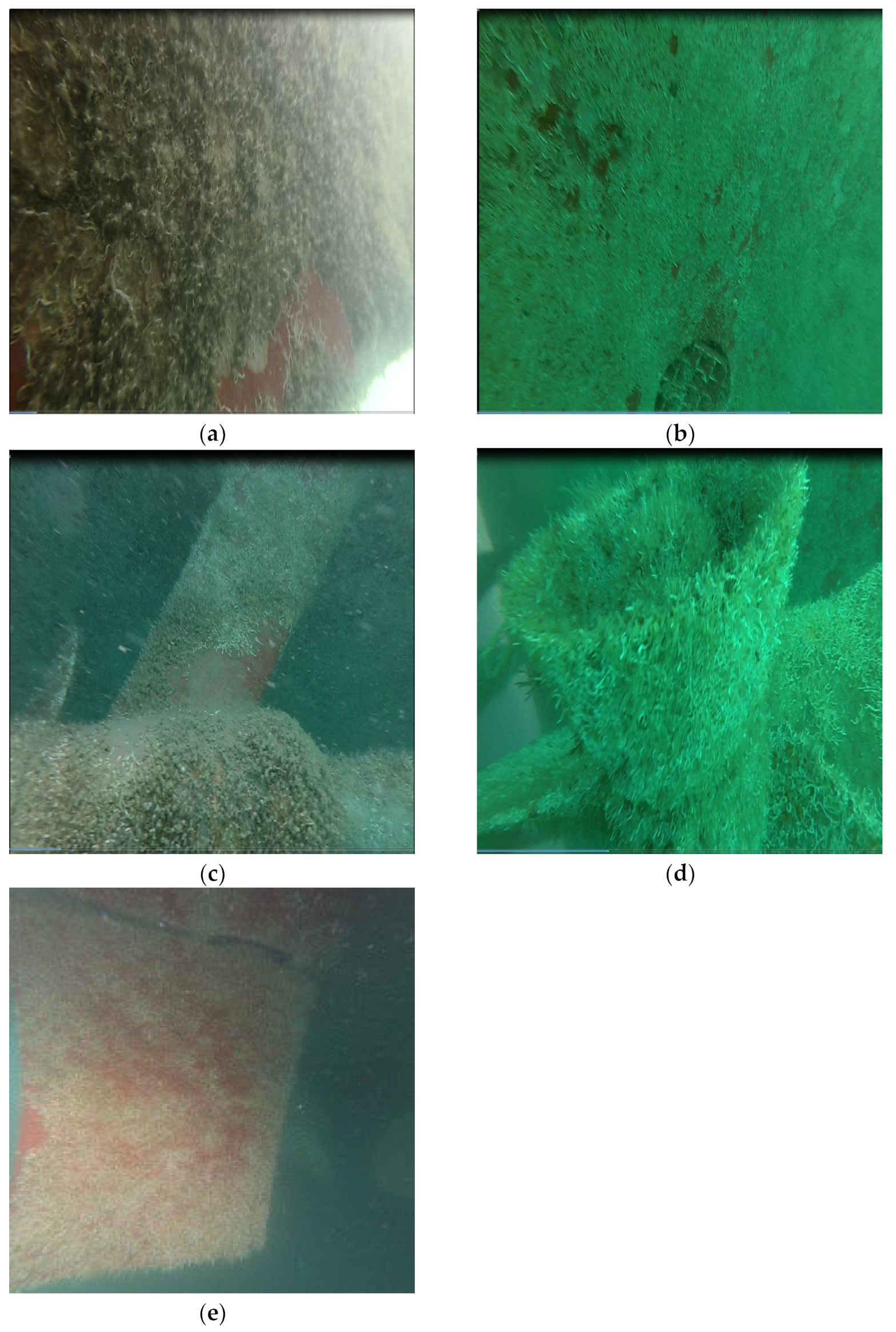
4.2. Perform an Underwater Inspection

The two ships were coated with self-polishing copolymer and tin-free nanotechnology paint, respectively, and were docked at the wharf for three months before undergoing dry-docking. As shown in Figure 9, the self-polishing copolymer paint exhibits significant marine organism adhesion on various parts of the hull, such as the seabed door, shafting, propeller, and rudder plate. Figure 10 illustrates that the tin-free nanotechnology paint on the hull exhibits less adhesion of marine organisms.

4.3. Sea Trial and Fuel Consumption Analysis

During the sea trial stage, this study conducted tests on two ships, each operating at six different speeds for one hour. The study observed and recorded the fuel consumption calculations for each speed. When the two ships needed to reach the design speed of 500 RPM, both types of coatings were able to reach the computer-set RPM. However, due to the varying amounts of marine biofouling on the coatings, the self-polishing copolymer required additional fuel injection to achieve the design speed. Taking the example of the six-speed ships, when coated with the self-polishing copolymer, their fuel consumption per hour was 2473 L. However, using the tin-free nanotechnology paint, oil consumption was reduced to 2403 L, resulting in a 3% decrease in the fuel consumption ratio, as shown in Table 7. Furthermore, the tin-free nanotechnology paint used on the ship’s main engine resulted in a smaller output load. This not only reduced fuel consumption but also increased the engine’s service life.

5. Conclusions

In this study, various models were utilized to observe the growth of marine organisms on steel plates with different surface treatments and paint types. Additionally, the fuel consumption of ships coated with self-polishing copolymer and tin-free nanotechnology paint was analyzed. The results indicate that self-polishing copolymer coatings are more prone to biological fouling. In contrast, tin-free nanotechnology paint, with its smaller molecular structure, tends to accumulate less biological fouling. Additionally, since tin-free nanotechnology paint does not contain tin, it reduces pollution in marine environments. The use of tin-free nanotechnology paint improves the output power of the main engine, resulting in reduced fuel consumption. These findings can serve as a reference for shipowners in their future selection of antifouling paints.

Author Contributions

Y.W. conceived, planned, and performed the designs and drafted this paper. C.H. provided guidance and reviewed this paper. Y.W., G.P. and C.C. provided the design ideas and edited this paper. All authors have read and agreed to the published version of the manuscript.

Funding

This research received no external funding.

Institutional Review Board Statement

Not applicable.

Informed Consent Statement

Not applicable.

Data Availability Statement

The data presented in this study are available on request from the corresponding author.

Conflicts of Interest

The authors declare no conflicts of interest.

References

  1. Andrewartha, J.; Perkins, K.; Sargison, J.; Osborn, J.; Walker, G.; Henderson, A. Drag Force and Surface Roughness Measurements on Freshwater Biofouled Surfaces. J. Bioadhesion Biofilm Res. 2010, 26, 487–496. [Google Scholar] [CrossRef] [PubMed]
  2. Song, S.; Demirel, Y.K.; Atlar, M. An Investigation into the Effect of Biofouling on the Ship Hydrodynamic Characteristics Using CFD. Ocean Eng. 2019, 175, 122–137. [Google Scholar] [CrossRef]
  3. Chambers, L.D.; Stokes, K.R.; Walsh, F.C.; Wood, R.J.K. Modern Approaches to Marine Antifouling Coatings. Surf. Coat. Technol. 2006, 201, 3642–3652. [Google Scholar] [CrossRef]
  4. Katranitsas, A.; Castritsi-Catharios, J.; Persoone, G. The Effects of a Copper-Based Antifouling Paint on Mortality and Enzymatic Activity of a Non-Target Marine Organism. Mar. Pollut. Bull. 2003, 46, 1491–1494. [Google Scholar] [CrossRef] [PubMed]
  5. Warnken, J.; Dunn, R.J.K.; Teasdale, P.R. Investigation of Recreational Boats as a Source of Copper at Anchorage Sites Using Time-Integrated Diffusive Gradients in Thin Film and Sediment Measurements. Mar. Pollut. Bull. 2004, 49, 833–843. [Google Scholar] [CrossRef] [PubMed]
  6. Soon, Z.Y.; Jung, J.-H.; Loh, A.; Yoon, C.; Shin, D.; Kim, M. Seawater Contamination Associated with In-Water Cleaning of Ship Hulls and the Potential Risk to the Marine Environment. Mar. Pollut. Bull. 2021, 171, 112694. [Google Scholar] [CrossRef] [PubMed]
  7. China Corporation Register of Shipping. Technical Circular No. 25. 2006. pp. 6–7. Available online: https://www.crclass.org/en/category/circulars/ (accessed on 10 August 2024). (In Chinese).
  8. International Maritime Organization. International Convention on the Control of Harmful Anti-Fouling Systems on Ships. 2016. Available online: https://www.imo.org/ (accessed on 10 August 2024).
  9. Dickon, H.; Brigitte, B. A Review of Surface Roughness in Antifouling Coatings Illustrating the Importance of Cutoff Length. J. Bioadhesion Biofilm Res. 2006, 22, 401–410. [Google Scholar]
  10. Schultz, M.P. Effects of Coating Roughness and Biofouling on Ship Resistance and Powering. J. Bioadhesion Biofilm Res. 2007, 23, 331–341. [Google Scholar] [CrossRef] [PubMed]
  11. Demirel, Y.K.; Mahdi, K.; Osman, T.; Atilla, I.; Schultz, M.P. A CFD Model for the Frictional Resistance Prediction of Antifouling Coatings. Ocean Eng. 2014, 89, 21–23. [Google Scholar] [CrossRef]
  12. Demirel, Y.K.; Turan, O.; Incecik, A. Predicting the Effect of Biofouling on Ship Resistance Using CFD. Appl. Ocean Res. 2017, 62, 100–118. [Google Scholar] [CrossRef]
  13. Monty, J.P.; Dogan, E.; Hanson, R.; Scardino, A.J.; Ganapathisubramani, B.; Hutchins, N. An Assessment of the Ship Drag Penalty Arising from Light Calcareous Tubeworm Fouling. Biofouling 2016, 32, 451–464. [Google Scholar] [CrossRef] [PubMed]
  14. Demirel, Y.K.; Uzun, D.; Zhang, Y.; Fang, H.C.; Day, A.H.; Osman, T. Effect of Barnacle Fouling on Ship Resistance and Powering. Biofouling 2017, 33, 819–834. [Google Scholar] [CrossRef] [PubMed]
  15. Demirel, Y.K.; Soonseok, S.; Osman, T.; Atilla, I. Practical Added Resistance Diagrams to Predict Fouling Impact on Ship Performance. Ocean Eng. 2019, 186, 106–112. [Google Scholar] [CrossRef]
  16. Naval Sea Systems Command. MIL-PRF-24647D, Performance Specification: Paint System, Anticorrosive and Antifouling, Ship Hull; Naval Sea Systems Command: Washington, DC, USA, 2005. [Google Scholar]
  17. SSPC-SP 10/NACE No. 2; Joint Surface Preparation Standard, Near-White Metal Blast Cleaning. The Society for Protective Coatings: Pittsburgh, PA, USA; NACE: Houston, TX, USA, 2007.
Figure 1. Experimental model material.
Jmse 12 01662 g001
Figure 2. Underwater inspection site (A) hull, (B) seabed doors, (C) shafting, (D) propeller, (E) rudder plates.
Jmse 12 01662 g002
Figure 3. Sea test voyage chart.
Jmse 12 01662 g003
Figure 4. Experimental model recording points.
Jmse 12 01662 g004
Figure 5. Model 1 underwater steel plate record: (a) Model 1 first week; (b) Model 1 fifth week; (c) Model 1 tenth week; (d) Model 1 fifteenth week.
Jmse 12 01662 g005
Figure 6. Model 2 underwater steel plate record: (a) Model 2 first week; (b) Model 2 fifth week; (c) Model 2 tenth week; (d) Model 2 fifteenth week.
Jmse 12 01662 g006
Figure 7. Model 3 underwater steel plate record: (a) Model 3 first week; (b) Model 3 fifth week; (c) Model 3 tenth week; (d) Model 3 fifteenth week.
Jmse 12 01662 g007
Figure 8. Model 4 underwater steel plate record: (a) Model 4 first week; (b) Model 4 fifth week; (c) Model 4 tenth week; (d) Model 4 fifteenth week.
Jmse 12 01662 g008
Figure 9. Self-polishing copolymer underwater inspection status: (a) hull plate; (b) seabed door; (c) shafting; (d) propeller; (e) rudder plate.
Jmse 12 01662 g009
Figure 10. Tin-free nanotechnology paint underwater inspection status: (a) hull plate; (b) seabed door; (c) shafting; (d) propeller; (e) rudder plate.
Jmse 12 01662 g010
Table 1. Coating system type, class, application matrix.
TypeClassApp1App2App3App4
I1YESYESYESYES
2YESYESYESYES
3YESYESYESNO
II1YESYESYESYES
2NONONONO
3YESYESYESNO
III1YESYESNOYES
2YESYESNOYES
3YESYESNONO
IV1YESNONONO
2YESNONONO
3YESNONONO
Table 2. Experimental model comparison table.
ModelSteel Plate MaterialSurface TreatmentTypes of Antifouling Paint
1EH36SSPC-SP 10self-polishing copolymer
2HY80SSPC-SP 10self-polishing copolymer
3EH36SSPC-SP 10tin-free nanotechnology paint
4HY80SSPC-SP 10tin-free nanotechnology paint
Table 3. The record table of the growth thickness of Model 1 in underwater sea conditions (unit: mm).
ModelRecord PointWeek 1Week 2Week 3Week 4Week 5
1M12.274.136.838.3810.54
M22.793.575.748.8112.86
M32.166.869.1312.0213.57
M43.135.615.9511.3712.28
M52.224.098.7910.3412.02
average value2.514.857.2910.1812.25
Record PointWeek 6Week 7Week 8Week 9Week 10
M116.2219.8322.6422.5523.69
M214.5415.9617.2520.1422.78
M314.8917.6822.4824.7625.36
M413.8714.2719.7121.3823.95
M514.6117.6418.8922.2425.62
average value14.8317.0820.1922.2324.28
Record PointWeek 11Week 12Week 13Week 14Week 15
M125.7927.1929.1130.1231.72
M223.8725.8426.2327.8729.12
M327.9528.4731.4831.9432.29
M424.2526.3828.6729.2230.36
M526.3628.1529.8530.2130.41
average value25.6427.2129.0729.8930.78
Table 4. The record table of the growth thickness of Model 2 in underwater sea conditions (unit: mm).
ModelRecord PointWeek 1Week 2Week 3Week 4Week 5
2M12.293.765.117.9211.83
M22.676.189.8911.3112.95
M32.214.746.2710.6812.16
M42.545.276.859.5711.69
M52.734.928.2311.2613.03
average value2.494.987.2710.1512.33
Record PointWeek 6Week 7Week 8Week 9Week 10
M115.5817.1618.3121.2824.74
M216.3919.0722.2923.7625.32
M314.3718.9222.3823.0424.12
M413.1416.2417.2522.8824.03
M515.9616.1718.5319.1520.97
average value15.0917.5119.7522.0223.84
Record PointWeek 11Week 12Week 13Week 14Week 15
M125.6127.1928.3529.5631.49
M226.8925.8428.4329.1330.17
M325.2528.4730.9831.2631.86
M425.8626.3828.1828.8529.10
M521.8228.1529.6430.4231.25
average value25.0927.2129.1229.8430.77
Table 5. The record table of the growth thickness of Model 3 in underwater sea conditions (unit: mm).
ModelRecord PointWeek 1Week 2Week 3Week 4Week 5
3M1000.440.851.06
M2000.510.911.20
M3000.320.651.18
M4000.490.881.13
M5000.480.931.16
average value000.450.841.15
Record PointWeek 6Week 7Week 8Week 9Week 10
M11.091.141.311.471.54
M21.211.271.361.421.51
M31.571.651.691.821.94
M41.191.251.481.711.73
M51.181.211.291.651.69
average value1.251.301.431.611.68
Record PointWeek 11Week 12Week 13Week 14Week 15
M11.771.831.892.122.15
M21.581.661.721.851.94
M31.982.022.112.232.25
M41.841.871.931.972.01
M51.731.761.801.982.04
average value1.781.831.892.032.08
Table 6. The record table of the growth thickness of Model 4 in underwater sea conditions (unit: mm).
ModelRecord PointWeek 1Week 2Week 3Week 4Week 5
4M1000.490.951.11
M2000.561.181.21
M3000.370.691.07
M4000.310.781.19
M5000.480.921.02
average value000.440.901.12
Record pointWeek 6Week 7Week 8Week 9Week 10
M11.221.271.341.421.42
M21.291.341.501.541.65
M31.111.191.561.681.69
M41.241.561.581.641.77
M51.131.211.321.471.54
average value1.201.311.461.551.61
Record pointWeek 11Week 12Week 13Week 14Week 15
M11.441.521.691.741.88
M21.821.891.992.282.33
M31.791.851.912.052.15
M41.891.932.022.102.13
M51.561.841.962.012.08
average value1.701.811.912.042.11
Table 7. Fuel consumption statistics table for self-polishing copolymer coatings and tin-free nanotechnology paint at various ship speeds.
Speed ModePaint Film MaterialEngine Design Speed (RPM)Average Engine Speed per Hour (RPM)Fuel Consumption Statistics (L)
1Self-polishing copolymer500500211
Tin-free nanotechnology paint499191
2Self-polishing copolymer10001001546
Tin-free nanotechnology paint1000520
3Self-polishing copolymer150015011493
Tin-free nanotechnology paint14971440
4Self-polishing copolymer180017991902
Tin-free nanotechnology paint17991584
5Self-polishing copolymer195019502381
Tin-free nanotechnology paint19472337
6Self-polishing copolymer210021582473
Tin-free nanotechnology paint20962403
Disclaimer/Publisher’s Note: The statements, opinions and data contained in all publications are solely those of the individual author(s) and contributor(s) and not of MDPI and/or the editor(s). MDPI and/or the editor(s) disclaim responsibility for any injury to people or property resulting from any ideas, methods, instructions or products referred to in the content.

