Article

Development and Validation of Reliability Testing Methods for Insulation Systems in High-Voltage Rotating Electrical Machinery on Ships

1
Eco-Friendly Propulsion Headquarters, Korea Marine Equipment Research Institute, Ulsan 44776, Republic of Korea
2
Division of Marine System Engineering, Korea Maritime & Ocean University, Busan 49112, Republic of Korea
*
Author to whom correspondence should be addressed.
J. Mar. Sci. Eng. 2025, 13(2), 186; https://doi.org/10.3390/jmse13020186
Submission received: 21 December 2024 / Revised: 17 January 2025 / Accepted: 18 January 2025 / Published: 21 January 2025
(This article belongs to the Section Ocean Engineering)

Abstract

:
Lloyd’s Register became the first classification society to mandate reliability testing for insulation degradation in rotating electrical machinery. As the maritime industry shifts toward eco-friendly practices, high-voltage rotating electrical machinery on ships increasingly features higher voltages and larger capacities. However, incidents involving insulation systems have also become more frequent. Additionally, testing facilities with the necessary equipment to perform such reliability tests are lacking, and standardized testing methods are yet to be established. This study proposes test items, methods, and evaluation criteria for the reliability testing of high-voltage rotating electrical machinery. The testing methods are broadly categorized into four types: thermal, electrical, multifactor, and thermomechanical degradation reliability testing. The proposed methods were validated by conducting long-term testing over approximately one year. Key results showed a breakdown time of 7056 h in thermal evaluation, 5040 h in electrical evaluation, and 258.5 d in multifactor evaluation, as well as a 63rd percentile value of 245.7 h in thermomechanical evaluation, all of which fulfill the required criteria. The study offers practical guidelines for ensuring the durability and safety of high-voltage electrical machinery, aligning with the sustainability and safety goals of the maritime industry.

1. Introduction

1.1. Background

Recently, the rated voltage of key onboard equipment, such as generators and motors, has been trending toward higher voltages. This shift is driven by factors such as the increasing size and capacity of ships, the push for eco-friendly initiatives, and the adoption of electric propulsion systems [1,2,3,4,5,6,7]. Consequently, reliability analysis of critical rotating electrical machinery onboard has become crucial to ensure stable operation, longevity, and safety.
The failure locations of high-voltage generators, a key type of rotating machinery, were identified as stator windings (50%), the exciter (18.5%), bearings (13.5%), rotor windings (7%), and other locations (11%) [8]. Stator winding failures were primarily caused by insulation degradation (44.9%), lightning strikes (26.3%), consequential damage (12.3%), and other causes (16.5%) [8]. Similarly, high-voltage motor failures were attributed to stator windings (46.4%), rotors (9.6%), bearings (28.8%), and other locations (15.2%) [3], with approximately 50% of these failures linked to insulation degradation in the stator windings [8,9].
Recent advancements in insulation systems for rotating electrical machinery have introduced innovative approaches to reliability testing. Partial discharge analysis is a highly effective method for diagnosing insulation degradation in high-voltage systems [10]. A high-voltage pulse generator was developed to evaluate insulation systems under the specific stresses introduced by inverter-fed motors, simulating electrical stresses up to 20 kV with precise control of rise and fall times [11]. The integration of corona-resistant wires in electrical machine designs, especially for more electric aircraft, has been investigated to enhance the insulation performance and mitigate the partial discharge phenomena [12,13,14]. Additionally, numerical simulation models have been employed to analyze insulation performance under complex operational conditions, enabling realistic assessments of electric machine parameters [15,16].
Experimental methods have also advanced significantly. Accelerated destructive experiments have been conducted to analyze insulation degradation in motor stator windings, providing precise measurement capabilities and insights into failure mechanisms [17,18]. Furthermore, studies have investigated the effects of multilevel inverter (MLI) configurations on dielectric stress in motor stator insulation, revealing that optimizing output voltage levels and waveform shapes can greatly reduce insulation stress [19]. A comprehensive review of insulation lifespan in low-voltage motors highlights the critical role of frequency converters in insulation degradation, emphasizing the need for tailored solutions for high-voltage systems [20]. Mathematical models, such as those developed for axial flux induction motors, have provided valuable tools to enhance motor designs by optimizing torque density and insulation reliability in compact applications [21].
Further advancements include the challenges of ensuring reliable dielectrics in modern aerospace applications, where corona-resistant materials have shown both benefits and risks [13,20]. Statistical reviews of voltage endurance tests for high-voltage rotating machine stator windings have introduced the “Three Steps Test” (TST) method to effectively combine standard and accelerated tests [18]. Studies on operational dynamics in self-propelled trains have provided insights into load distribution and mechanical stress, which can inform approaches to insulation system resilience under dynamic loads [14]. Additionally, experimental investigations of gamma Stirling refrigerators have highlighted thermal stress interactions that offer valuable parallels for insulation reliability in harsh environments [16].
Despite these advancements, most studies focus on land-based applications and do not address the unique environmental stressors faced by shipboard systems. For instance, maritime environments involve prolonged exposure to high humidity, saltwater spray, and dynamic mechanical loads caused by waves and engine vibrations. These stressors necessitate customized testing methods that go beyond standard approaches for land-based equipment. Additionally, high-voltage shipboard systems often operate under stricter reliability requirements, owing to their critical role in ensuring safe and efficient vessel operations.
In response, international classification societies have mandated reliability tests for insulation systems in high-voltage rotating electrical machinery used on ships [17,18]. Among these, Lloyd’s Register was the first to announce, based on Rule Proposal No. 2015/EL01 (Rules and Regulations for the Classification of Ships, 2016), that classification certification for generators and motors contracted after July 2016 should include results of insulation degradation reliability tests conducted in accordance with international standards (IEC 60034-18-31, IEC 60034-18-32, IEC 60034-18-33, and IEC 60034-18-34) [22,23,24,25]. However, although international classification societies outline the standards, specific test instruments and methods are yet to be established, rendering their development an urgent priority.
This paper presents the development of test equipment and methods that conform to the reliability testing standards for high-voltage machinery on ships, the establishment of testing facilities, and the results of reliability tests. These efforts have been reviewed and approved by Lloyd’s Register, making this the first instance of conducting insulation reliability tests for high-voltage rotating electrical machinery used on ships. This milestone is deemed a highly valuable achievement.
By addressing multifactorial stressors, including thermal, electrical, and mechanical effects, this study bridges the gap between existing land-based testing approaches and the unique challenges of maritime environments. Approved by Lloyd’s Register, it marks a key step in standardizing shipboard insulation system evaluations, supporting the sustainability and safety goals of the maritime industry.

1.2. Limitations of Previous Methods

Most previous studies have been limited to high-voltage rotating machinery used on land [26,27,28,29,30,31,32,33,34,35,36,37,38,39,40,41,42,43,44,45,46,47,48,49,50,51,52,53,54,55,56], and no cases of reliability testing that fully reflects the harsh environmental conditions of ships have been reported. Research in the field of high-voltage rotating machinery reliability has primarily focused on three main areas: insulation diagnostic methods, lifespan prediction methods, and improving insulation performance [26,27,28,29,30,31,32,33,34,35,36,37,38,39,40,41,42,43,44,45,46,47,48,49,50,51,52,53,54,55,56].
Although previous studies have explored various methods to diagnose high-voltage rotating machinery conditions, no studies have focused on reliability testing specifically for ships. Moreover, systematic reliability test equipment and methods to address the major degradation factors suspected to cause failures, namely thermal, electrical, multifactor (thermal and electrical), and thermomechanical degradation, are lacking.

1.3. Comparison with Reliability Standards in Other Industries

Reliability standards in the automotive, railway, and aerospace industries provide valuable insights into environmental testing for electrical systems. For example, ISO 16750 in the automotive industry addresses moderate road vibrations and temperature variations [57]. EN 50155 in the railway industry emphasizes durability under sustained vibrations and high humidity, while RTCA DO-160 in the aerospace industry focuses on extreme conditions, such as rapid temperature changes, high-altitude pressures, and intense vibrations [58,59].
Contrastingly, shipboard environments involve prolonged exposure to unique stresses, including saltwater spray, high humidity, and dynamic mechanical loads caused by waves and engine operations. While IEC 60034 serves as the primary standard for high-voltage rotating electrical machinery, it requires additional multifactorial assessments to consider the distinct challenges of maritime applications. This comparison highlights the need for specialized testing methods tailored to shipboard conditions, ensuring reliability under complex and prolonged stress environments [22,23,24,25].
The methods proposed in this study, while reviewed and approved by Lloyd’s Register, were developed to address gaps in maritime-specific testing of high-voltage rotating electrical machinery. This study focuses on creating tailored testing criteria for maritime environments, emphasizing the novel combination of multifactorial stress evaluations that have not been addressed in existing standards.

2. Materials and Methods

Existing rotating electrical machinery used on ships has only undergone initial quality tests, with no reliability tests conducted to evaluate lifespan. Although classification societies have recently begun enforcing stricter standards, no test items, methods, or evaluation criteria for such tests have been established. Furthermore, the absence of testing equipment and dedicated facilities highlights the urgent need for the development of reliability testing methods.
This paper proposes test methods, configurations, and evaluation criteria for reliability analysis of high-voltage insulation systems on ships, which are currently undefined. The proposed basic flowchart for reliability testing of shipboard high-voltage insulation systems is shown in Figure 1. The process begins with an initial quality test on the specimens, followed by aging tests (thermal, electrical, multifactor, and thermomechanical degradation). These tests are iteratively conducted for approximately ten cycles. When a specimen fails, the insulation breakdown time is recorded, and the mean time to failure for each test specimen is calculated.
Table 1 lists the initial quality test items and aging test items for the insulation systems of high-voltage rotating machinery used onboard ships. The initial quality test items for each degradation factor are enumerated, and the aging tests are categorized into aging, conditioning, and diagnostic tests, with the respective test items listed accordingly. The initial quality tests were conducted once before the commencement of aging tests, while the aging tests were conducted over approximately ten cycles.

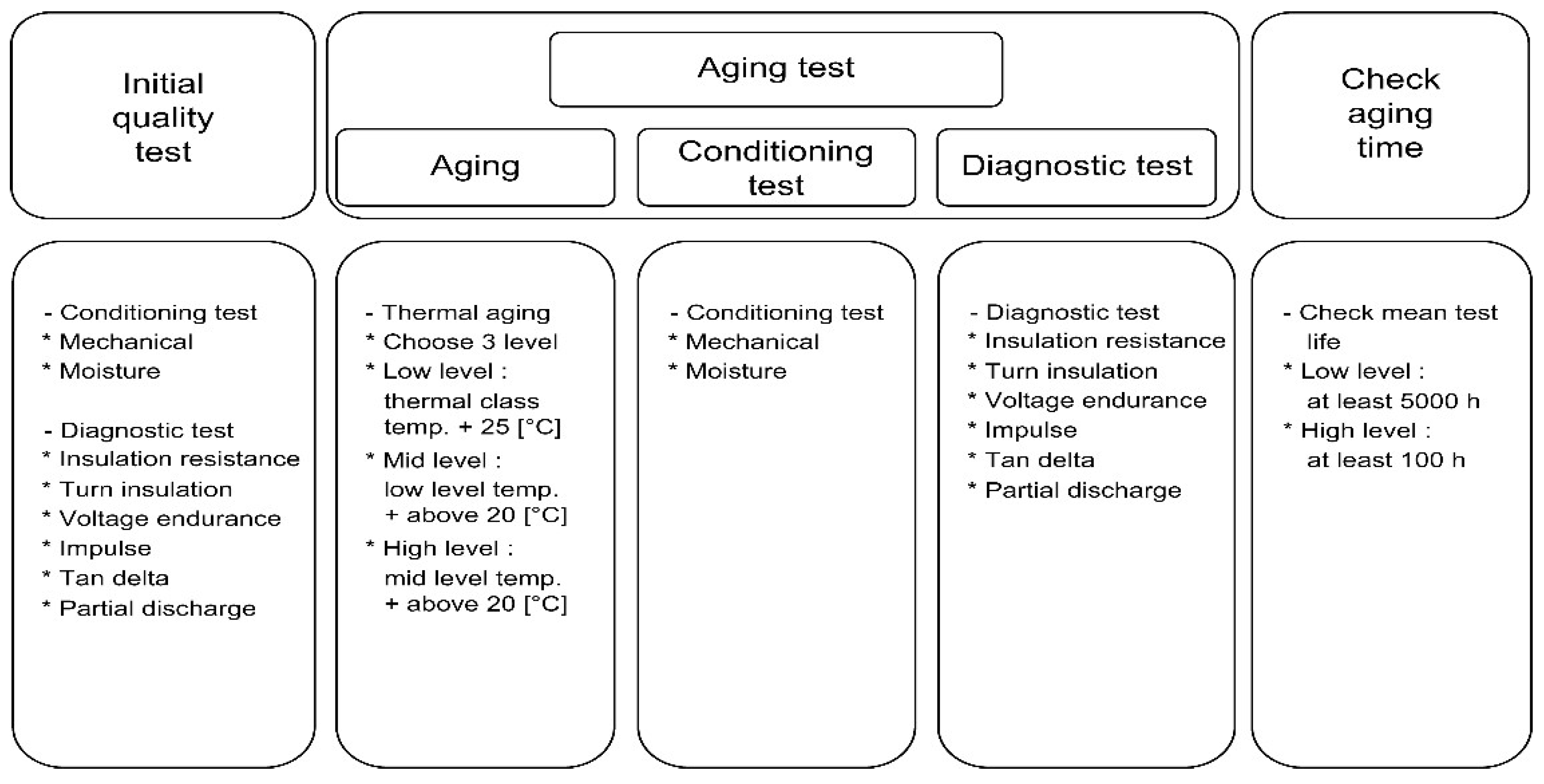
2.1. Thermal Evaluation

The thermal degradation test method involves iteratively conducting initial quality tests, followed by aging, conditioning, and diagnostic tests for approximately ten cycles. Upon completing approximately ten cycles, the specimen is considered reliable if the mean time to failure is at least 5000 h and 100 h at the lowest and highest temperatures, respectively. The relationship between temperature ( T ) and breakdown time ( t ) can be modeled using the Arrhenius equation [60]:
t = A exp ( E a k T )
where t is the breakdown time (h); A is the experimentally determined pre-exponential factor (h); E a is the activation energy (eV), representing the energy barrier for thermal degradation; k is the Boltzmann constant ( 8.617 × 10 5 eV/K); and T is the absolute temperature (K).
Equation (1) mathematically describes how higher temperatures accelerate thermal degradation, reducing breakdown time. It provides a quantitative framework for comparing experimental results across the tested temperature levels (180 °C, 210 °C, and 230 °C).
Figure 2 shows a flowchart that illustrates the thermal degradation test. In the initial quality test, vibration tests were conducted for 1 h at 60 Hz. The amplitude of the vibrations was 0.2 mm at 60 Hz. Humidity tests were conducted for 48 h in a constant temperature and humidity chamber at 25 °C and 95% relative humidity, ensuring visible moisture distribution on the specimen surface.
Insulation resistance tests were conducted using an MIT1525 instrument (Megger, Dover, UK) before and after the turn insulation test and after the dielectric strength test. In accordance with IEC 60034-27-4 [54], a DC voltage of 2500 V was applied for 1 min. In the turn insulation test, a voltage 0.2 times the sum of the rated voltage and 1 kV was applied for 1 min. The dielectric strength test was conducted by applying a voltage twice the rated voltage for 1 min. The impulse tests were conducted under the voltage conditions specified in IEC 60034-15 [55]. The dielectric dissipation factor was measured at voltages of 0.2, 0.4, 0.6, 0.8, and 1.0 times the rated voltage. ΔTAN represents the difference between the dielectric dissipation factors at the rated voltage and 0.2 times the rated voltage. The partial discharge test was conducted at the rated voltage; the voltage was gradually increased to identify the inception voltage of partial discharge. For the F-class insulation system (155 °C), the low level was set at 180 °C, the intermediate level at 210 °C, and the high level at 230 °C. Using the Arrhenius equation, the breakdown time observed at these temperatures can be analyzed to estimate the activation energy ( E a ) for the insulation material. This analysis helps validate the thermal reliability of the insulation system and ensures compliance with the acceptance criteria of 5000 h at the lowest level and 100 h at the highest level. The conditioning and diagnostic tests were conducted via the same methods used for the initial quality test. The test methods and procedures were developed based on Lloyd’s Register’s Rule Proposal No. 2015/EL01 (Rules and Regulations for the Classification of Ships, 2016) [56].

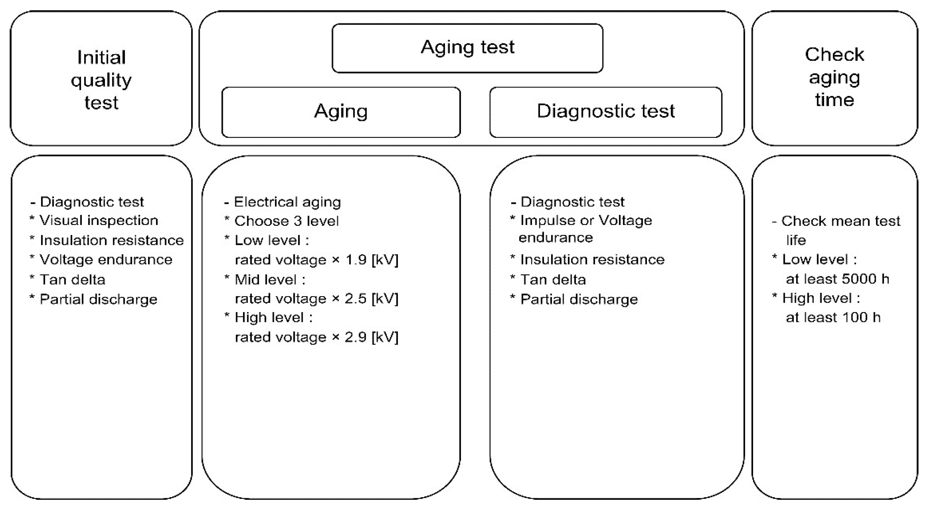
2.2. Electrical Evaluation

The test method for electrical degradation involved conducting initial quality tests, followed by iteratively conducting aging tests for approximately 10 cycles. Subsequently, reliability was ensured if the mean time to failure was at least 5000 h and 100 h at the lowest and highest levels, respectively. The relationship between the applied voltage ( V ) and breakdown time ( t ) can be described using a power-law model [23,61]:
t = C × V n
where t is the breakdown time (h); V is the applied voltage (times the rated voltage); C is a material-dependent constant (h); and n is the voltage endurance coefficient, representing the sensitivity of the insulation material to voltage stress.
Equation (2) expresses that a higher voltage stress accelerates insulation degradation, resulting in shorter breakdown times. For this study, the voltage endurance coefficient ( n ) was calculated based on experimental data from aging tests conducted at 1.9, 2.5, and 2.9 times the rated voltage.
Figure 3 presents a flowchart that illustrates the electrical degradation test.
In the initial quality test, visual inspection was conducted to check for abnormalities such as discoloration, bubbles, and cracks. The insulation resistance test was performed after the dielectric strength test by applying a DC voltage of 2500 V for 1 min [54]. In the dielectric strength test, a voltage equivalent to twice the rated voltage plus 1 kV was applied. The dielectric dissipation factor was measured at voltages of 0.2, 0.4, 0.6, 0.8, and 1.0 times the rated voltage. ΔTAN represents the difference between the dielectric dissipation factors at the rated voltage and 0.2 times the rated voltage. Partial discharge measurements were performed at the rated voltage, and the voltage was gradually increased to determine the inception voltage of partial discharge.
Aging tests were conducted on a minimum of three levels. Each aging sub-cycle contained approximately ten cycles. The lowest, intermediate, and highest levels were defined as voltages 1.9, 2.5, and 2.9 times the rated voltage, respectively. Using the power-law model, the experimental breakdown times at these voltage levels were analyzed to estimate the voltage endurance coefficient (n). This analysis presents a quantitative basis to evaluate the electrical reliability of the insulation system under high-voltage stress conditions. Diagnostic tests, either impulse or dielectric, were performed after aging, and the applied test voltage was higher than the aging voltage, in accordance with IEC 60034-15 [55]. The other diagnostic tests were conducted via the methods used for the initial quality test. For the newly developed insulation system, diagnostic tests were not performed during each cycle. The test methods and procedures were developed based on Lloyd’s Register’s Rule Proposal No. 2015/EL01 (Rules and Regulations for the Classification of Ships, 2016) [56].

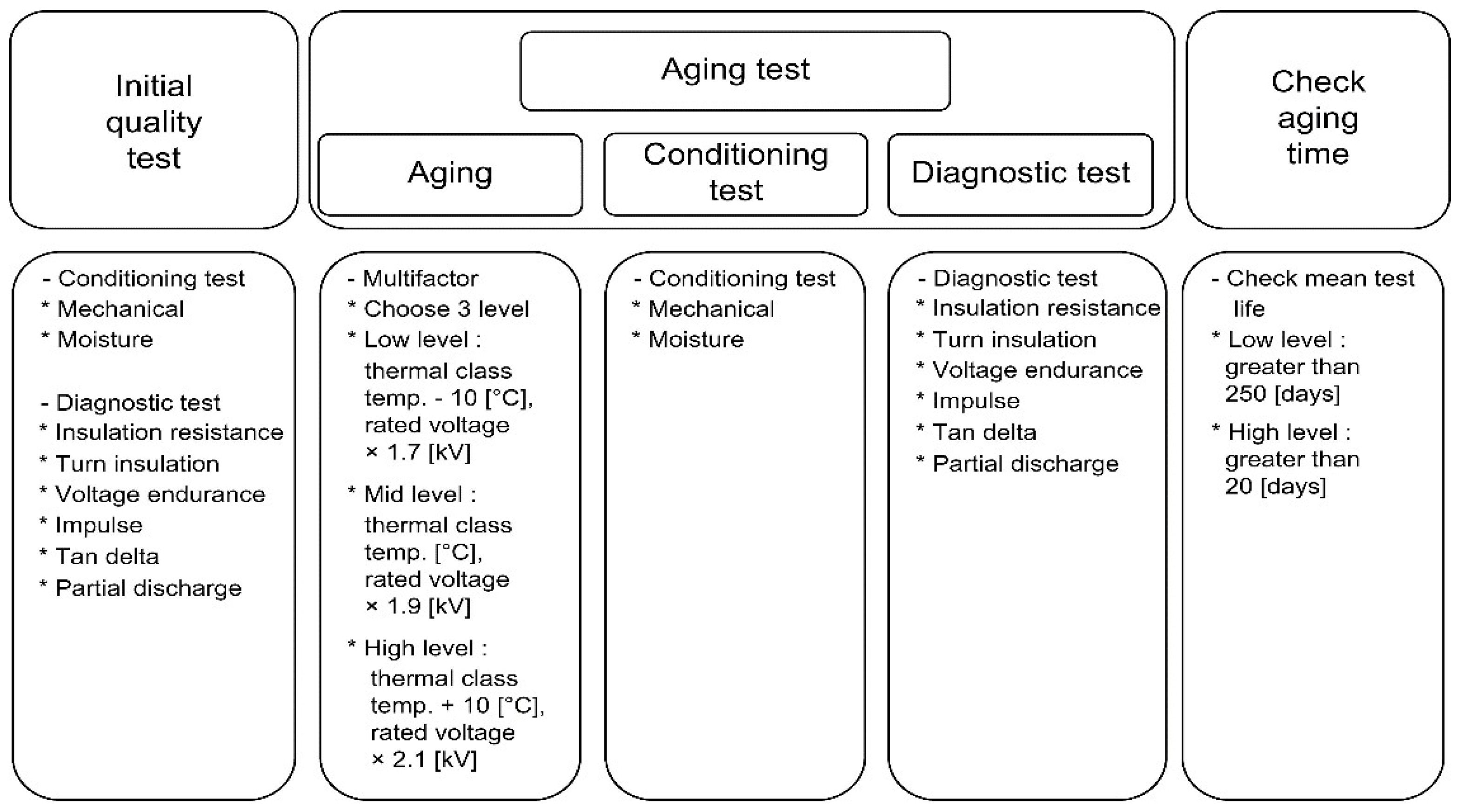
2.3. Multifactor Evaluation (Thermal + Electrical)

Initial quality tests and the subsequent aging, conditioning, and diagnostic tests were iteratively conducted for approximately 10 cycles to evaluate multifactor degradation. The specimens were considered reliable if the mean time to failure exceeded 250 d and 20 d at the lowest and highest levels, respectively, after approximately ten cycles. Figure 4 shows a flowchart that illustrates the multifactor degradation test.
In the initial quality test, vibration tests were conducted for 1 h at 60 Hz. The amplitudes of the vibrations were 0.2 mm at 60 Hz. Humidity tests were conducted for 48 h in a constant temperature and humidity chamber at 25 °C and 95% relative humidity, ensuring visible moisture distribution on the specimen surface. Additionally, visible moisture distribution was ensured on the specimen surface.
The insulation resistance test was performed following the dielectric strength test by applying a DC voltage of 2500 V for 1 min. The dielectric strength test was conducted by applying a voltage twice the rated voltage for 1 min. The impulse tests were conducted under the voltage conditions specified in IEC 60034-15 [55]. The dielectric dissipation factor was measured at voltages 0.2, 0.4, 0.6, 0.8, and 1.0 times the rated voltage. ΔTAN represents the difference between the dielectric dissipation factors at the rated voltage at 0.2 times the rated voltage. Partial discharge tests were conducted at the rated voltage, and the voltage was gradually increased to determine the inception voltage of partial discharge.
For the F-class insulation system (155 °C), at the low level, a voltage 1.7 times the rated voltage (6.6 kV) was applied at 145 °C, which is 10 °C lower than the class temperature. At the intermediate level, a voltage 1.9 times the rated voltage was applied at the class temperature. At the high level, a voltage 2.1 times the rated voltage was applied at 165 °C, which is 10 °C higher than the class temperature.
The combined effects of thermal, electrical, and mechanical stresses on the insulation system’s degradation were evaluated using a multifactor stress interaction model [24,62]:
σ t o t a l = σ 2 t h e r m a l + σ 2 e l e c t r i c a l + σ 2 m e c h a n i c a l  
where σ t o t a l is the combined stress σ t h e r m a l is stress due to thermal conditions, σ e l e c t r i c a l is stress due to electrical conditions, and σ m e c h a n i c a l is stress due to mechanical conditions (e.g., vibration).
Equation (3) quantifies the total stress ( σ t o t a l ) as the root-sum square of the individual stresses. It provides a mathematical basis for understanding how the insulation system responds to simultaneous stressors during testing.
The conditioning and diagnostic tests were performed via the same methods used for the initial quality test. The test methods and procedures were developed based on Lloyd’s Register’s Rule Proposal No. 2015/EL01 (Rules and Regulations for the Classification of Ships, 2016) [56].

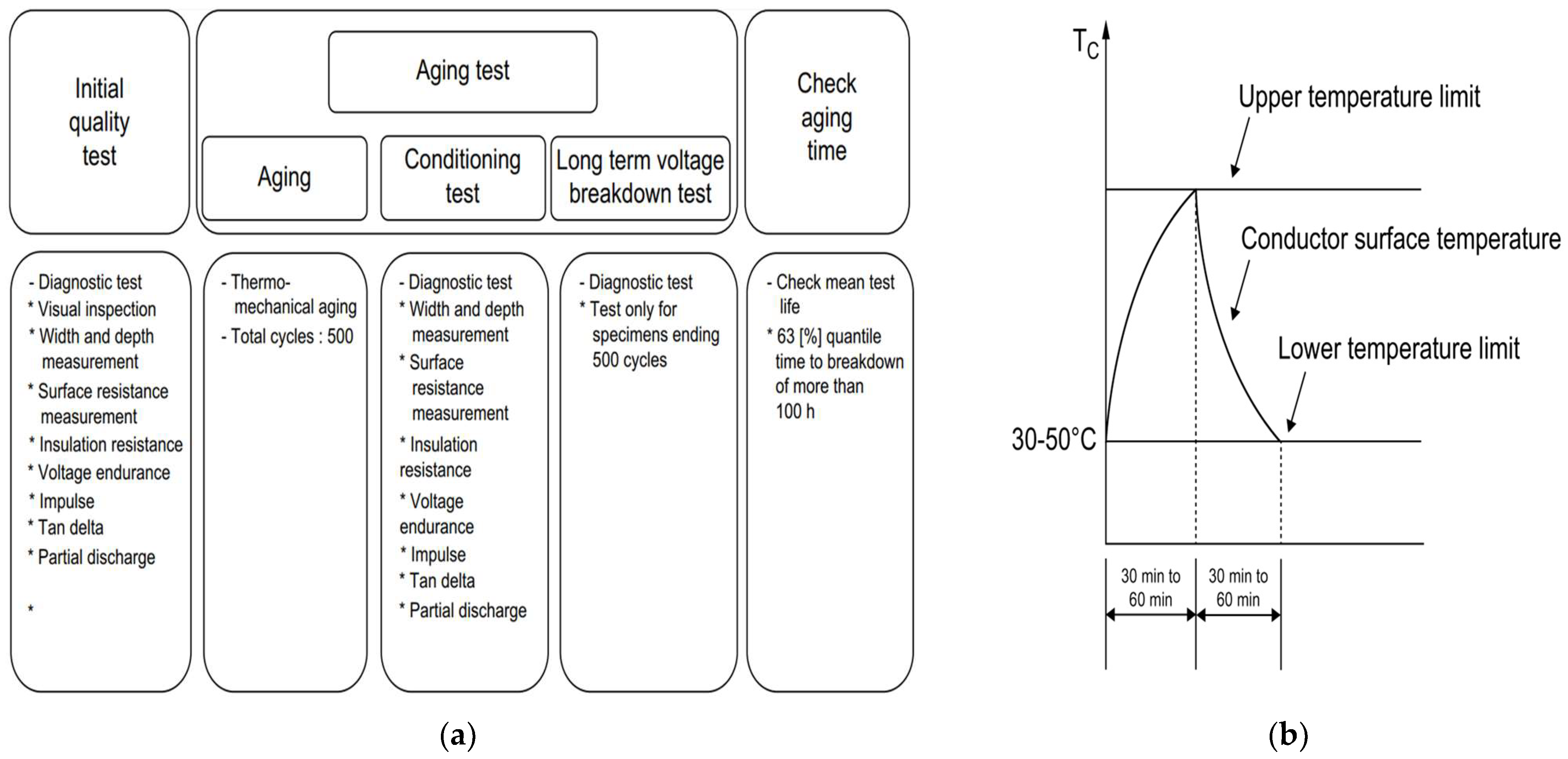
2.4. Thermomechanical Evaluation
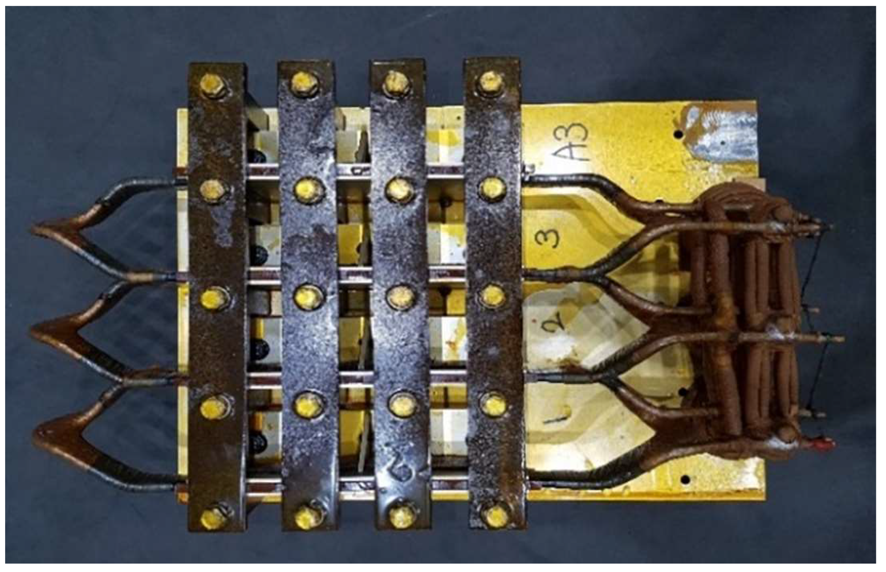
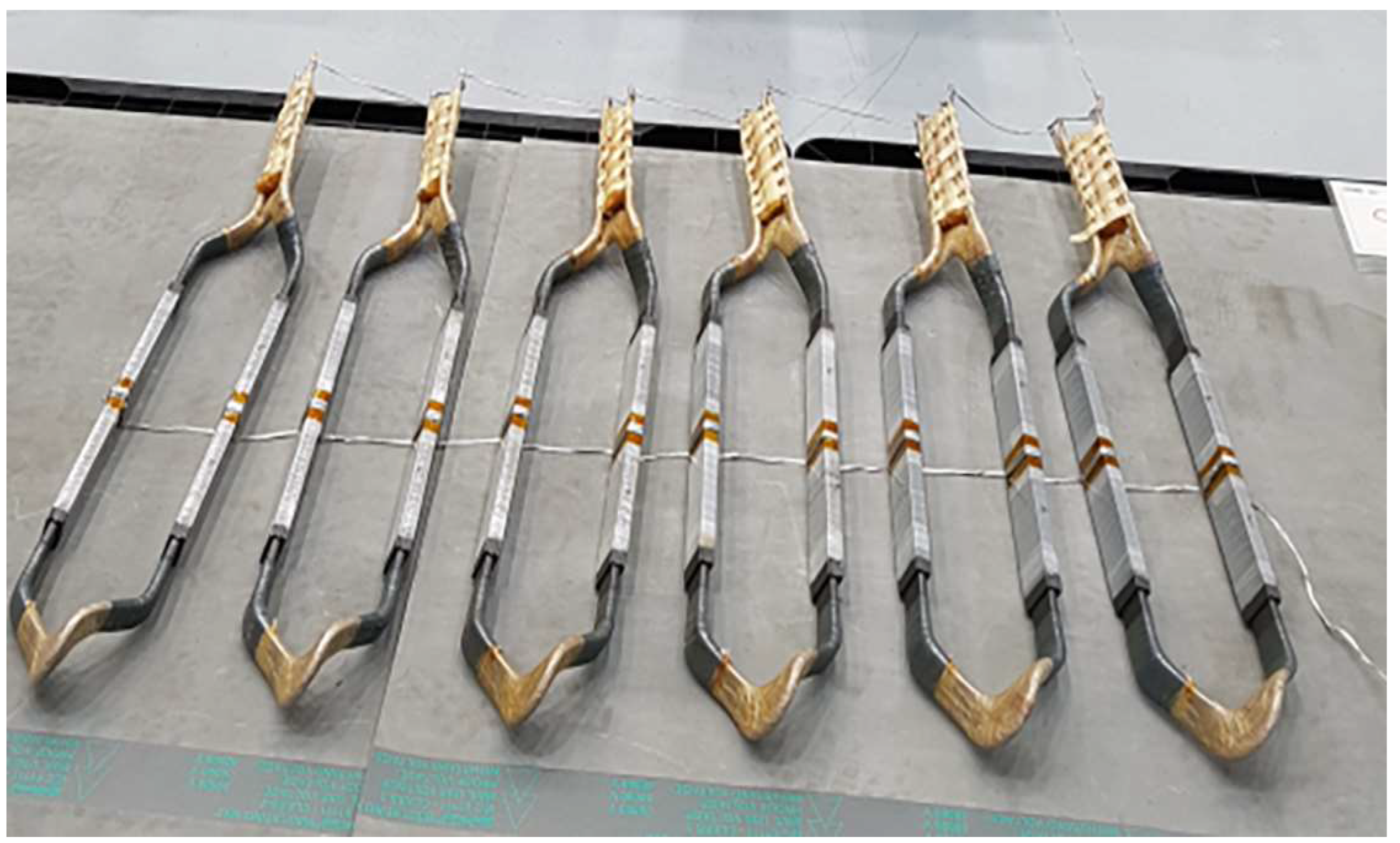
Initial quality tests were conducted to assess thermomechanical degradation, followed by aging tests for 500 cycles. Diagnostic tests were performed after 10, 50, 100, 250, and 500 cycles during the aging test. The breakdown voltage test was conducted upon the completion of 500 cycles. The specimens were considered reliable if 63 percentiles of the insulation-breakdown time exceeded 100 h when the specimens were destroyed [34].
A flowchart that illustrates the thermomechanical degradation test is shown in Figure 5. In the initial quality test, visual inspection was conducted to detect abnormalities such as discoloration, bubbles, and cracks. The widths and thicknesses of the specimens were measured using vernier calipers. Surface-resistance measurements were performed using an SRM200 instrument (DPV Elektronik-Service GmbH, Eppingen, Germany). The insulation resistance test was performed following the dielectric strength test by applying a DC voltage of 2500 V for 1 min. For the dielectric strength test, we applied a voltage twice the rated voltage plus 1 kV for 1 min. The impulse tests were conducted under the voltage conditions specified in IEC 60034-15 [55]. The dielectric dissipation factor was measured at voltages 0.2, 0.4, 0.6, 0.8, and 1.0 times the rated voltage. ΔTAN represents the difference between the dielectric dissipation factors at the rated voltage and at 0.2 times the rated voltage. Partial discharge measurements were performed at the rated voltage, and the voltage was gradually increased to determine the inception voltage of partial discharge.
For aging tests, the temperature was increased by passing a current through the specimen to increase the temperature of the conductor. Cooling was achieved through natural or forced-air cooling. The maximum temperature was set as the insulation-class temperature, while the minimum temperature was set in the range of 30–50 °C. The temperature was increased until the insulation-class temperature was reached. Subsequently, it was reduced to the range of 30–50 °C after cooling, constituting one cycle. The time taken for the temperature to rise and cool was between 30 and 60 min. Cycle tests were conducted based on the F-class (155 °C) insulation system. The tests were repeated for 500 cycles, and diagnostic tests were conducted after the 10th, 50th, 100th, 250th, and 500th cycles, following the same methods as those followed for the initial quality test. The test methods and procedures were developed based on Lloyd’s Register’s Rule Proposal No. 2015/EL01 (Rules and Regulations for the Classification of Ships, 2016) [56].

2.5. Test Specimens

To test the reliability of the insulation system for high-voltage rotating electrical equipment, test specimens were prepared using commercially available insulation systems currently supplied to ships. The specimens were approximately 50 cm in length, with a rated voltage of 6.6 kV. The number of specimens was set to at least five per level for each degradation factor. To enhance reliability, the number of specimens was determined based on the maximum capacity that could be accommodated by the specifications of the established testing equipment. For thermal evaluation, nine specimens were prepared for the lowest level, nine for the intermediate level, and six for the highest level. For multifactor evaluation, five specimens were prepared for the lowest level, six at the intermediate level, and six at the highest level. Figure 6 shows the specimens used for thermal and multifactor tests.
The insulation system was composed of mica-based corona and semi-corona insulation materials, ensuring the integrity of the epoxy resin. The insulation layer above the conductor was constructed via a taping process. The epoxy resin penetrated the void spaces between the layers via vacuum pressure impregnation. Six specimens were prepared for electrical and thermomechanical testing for each level, in contrast to the thermal or multifactor test specimens. The specimens were individually prepared to ensure smooth insulation and current flow. Figure 7 displays photographs of the specimens used for electrical and thermomechanical tests.

3. Results and Discussion
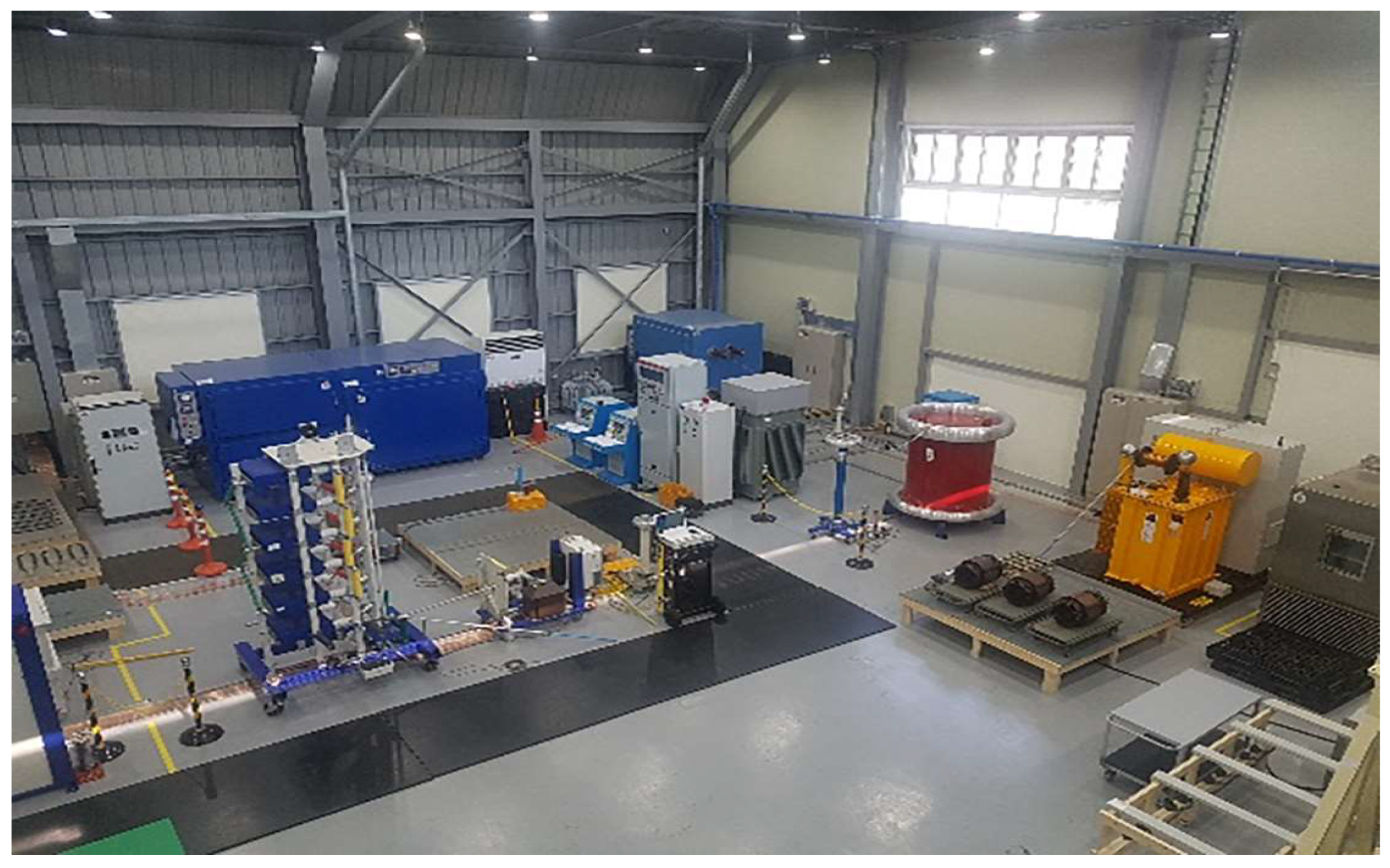
3.1. Testing

Testing equipment can be broadly categorized into conditioning, insulation diagnosis, and aging equipment. Conditioning equipment included a vibration tester and a constant temperature and humidity chamber. The insulation diagnosis equipment included a megger (MIT1525, Megger, Dover, Kent, UK, 15 kV), a tan delta tester (MIDAS 2881g, Haefely, Basel, Switzerland, 15 kV), a partial discharge tester (Haefely DDX-9121b, Haefely, Basel, Switzerland, 100 kV), a voltage-withstanding tester (MIDAS 2881g, Haefely, Basel, Switzerland, 15 kV), and an impulse tester (Haefely CS 600, Haefely, Basel, Switzerland, 600 kV). The aging equipment comprised a dry oven, a voltage-withstanding tester, and a load-cycle tester. Testing was conducted using equipment available at the High-Voltage Lifespan Evaluation Laboratory of the Korea Marine Equipment Research Institute. Figure 8 presents an overview of the High-Voltage Lifespan Evaluation Laboratory at the Korea Marine Equipment Research Institute (KOMERI).

3.2. Test Results and Conformation with Evaluation Criteria

The test results are summarized in Table 2.
For thermal evaluation, no breakdown specimens were observed at the low level. At the intermediate level, one specimen exhibiting electrical breakdown (1584 h) was observed, and three specimen breakdowns (144 h, 240 h, and 384 h) were observed at the high level. Consequently, the average breakdown time at the low level was 7056 h, and at the high level, it was 488 h, fulfilling the evaluation criteria.
For electrical evaluation, no breakdown specimens were observed at low and intermediate levels. At the high level, three specimen breakdowns (56 h, 86 h, and 116 h) occurred. Consequently, the average breakdown time was 5040 h at the low level and 142 h at the high level, satisfying the evaluation criteria.
For multifactor evaluation, two specimen breakdowns at the low level (5445 h and 6348 h), five specimen breakdowns at the intermediate level (398 h, 399 h, 401 h, 627 h, and 674 h), and two specimen breakdowns at the high level (434 h and 457 h) were observed. Thus, the average breakdown time was 258.5 d at the low level and 20.8 d at the high level, fulfilling the evaluation criteria. For thermomechanical evaluation, breakdown voltage tests were performed on specimens that completed 500 aging cycles. The breakdown times of the specimens were 200.6 h, 233.3 h, 233.6 h, 237.7 h, 245.0 h, and 276.0 h. Using the MINITAB (www.minitab.co.kr) program to estimate the 63% quantile time, a value of 245.7 h was determined, fulfilling the evaluation criteria.

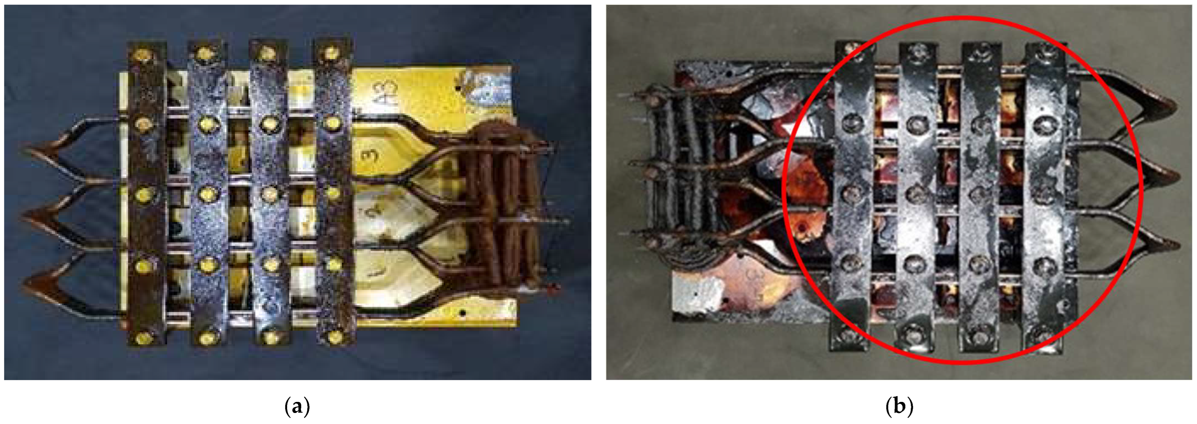
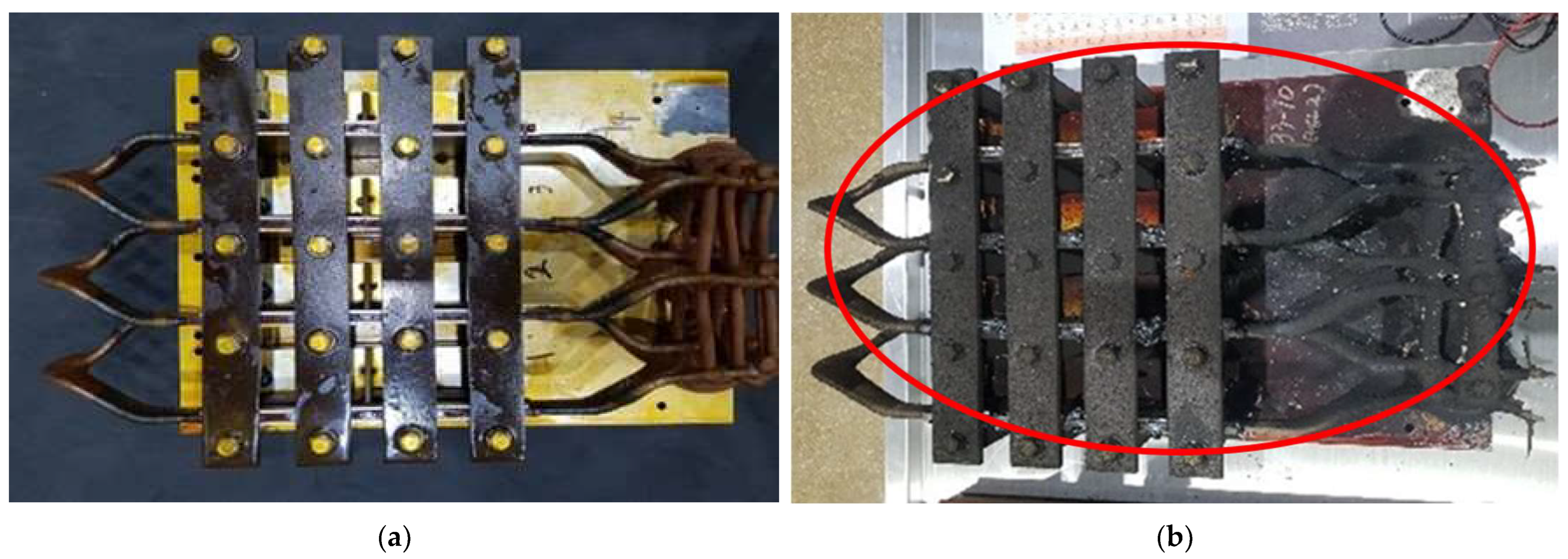
3.3. Specimens Before and After Testing

The changes in the specimens before and after approximately one year of testing for each degradation factor are shown in Figure 9, Figure 10, Figure 11 and Figure 12. Compared to the initial specimens, the specimens appeared darker and charred after undergoing thermal and multifactor degradation. During electrical evaluation, the specimens exhibited a corona discharge at the grading bushings as the cycles progressed, gradually resulting in whitening. Ultimately, insulation breakdown was observed.

3.4. Discussion

In the past, rotating electrical machinery on ships, with the exception of specialized large motors, such as bow-thruster motors, primarily comprised low-voltage machinery rated at 1000 V or below. These machines only underwent initial quality tests before delivery and installation. However, with shifts in shipbuilding trends, high-voltage rotating electrical machinery is now being installed on ships, necessitating long-term reliability verification. The test items, methods, and evaluation criteria proposed in this study enable such verification. By ensuring the stable operation, longevity, and safety of high-voltage rotating electrical machinery on ships, this approach contributes to the improve safety of lives and assets, as well as to the safe operation of vessels.
High-voltage rotating electrical machinery on ships is subject to more diverse environmental influences than similar machinery on land, necessitating consideration of these factors. Thus, the test process incorporates vibration tests to consider mechanical impacts and humidity tests to simulate damp marine environments. These tests were conducted to verify their suitability, and their effectiveness was confirmed. The results demonstrated that the insulation systems maintained their integrity under simulated shipboard conditions, including mechanical vibration and high humidity. These findings align with previous studies that highlight the significance of environment-specific testing to ensure reliable performance in maritime applications. This approach addresses a significant gap in the current industry standards, where land-based test conditions have often failed to replicate the operational challenges faced onboard ships.
High-voltage rotating electrical machinery with rated voltages exceeding 1000 V has been supplied to ships for many years. However, the long-term reliability of these machines is not generally assured, resulting in ongoing controversy. With the increasing adoption of high-voltage rotating electrical machinery on ships, international classification societies have started to require reliability verification of insulation systems to ensure safety.
Lloyd’s Register was the first to mandate such testing, and it is expected that other classification societies will follow suit. This paper presents the first case where the proposed test items, methods, and evaluation criteria have been reviewed and approved by Lloyd’s Register. This approval highlights the practical applicability of the proposed methods and sets a new benchmark for ensuring the reliability of insulation systems in maritime high-voltage rotating electrical machinery.
The results of the long-term reliability tests provide valuable insights into the performance and durability of insulation systems in shipboard high-voltage rotating electrical machinery. These findings were evaluated in the context of compliance with industry standards and existing research to ensure objective and scientifically supported conclusions. The thermal evaluation demonstrated a mean breakdown time of 7056 h under the low level, significantly exceeding the industry standard of 5000 h (IEC 60034-18-31).
This robust performance can be attributed to the use of high-quality materials and optimized design practices. Similarly, the electrical evaluation showed a mean breakdown time of 5040 h, validating the ability of the system to endure prolonged electrical stress, a critical requirement for high-voltage maritime applications. The multifactor evaluation revealed a breakdown time of 258.5 d under the low level, reflecting the combined resilience of the insulation system when exposed to simultaneous thermal and electrical stresses. This finding aligns with the theoretical predictions of stress interaction models, further validating the proposed methods. The thermomechanical evaluation, with a 63rd percentile quantile time of 245.7 h, highlights the durability of the system under combined mechanical and thermal stresses. Observations of test specimens revealed minor surface cracking and delamination following prolonged exposure to thermal cycling and mechanical vibrations. These findings align with theoretical stress models and indicate that the primary failure mechanism is material fatigue owing to stress concentration. Such insights are critical for the optimization of material composition and design to improve resilience in real-world shipboard applications. These results collectively demonstrate that the proposed test methods and evaluation criteria effectively assess the reliability of insulation systems for shipboard applications. By exceeding industry standards and aligning with the requirements outlined in IEC 60034-18-31 through IEC 60034-18-34, this study offers a scientifically robust framework to ensure safety and reliability in maritime electrical systems. Additionally, the findings provide a foundation for future studies aimed at optimizing insulation systems for more challenging operational environments.
This study provides a testing method for evaluating insulation systems in shipboard high-voltage rotating electrical machinery, but several limitations remain. First, future research should expand the work to include high-stress conditions and extreme operational scenarios, such as rapid temperature fluctuations, dynamic mechanical loads, and exposure to saltwater spray. Incorporating these conditions would offer a more comprehensive understanding of insulation system performance onboard ships. Second, this study did not address the long-term effects of inverter surges generated by drive modules in electrically powered ships. As the maritime industry increasingly adopts electric propulsion systems, it is crucial to investigate the impact of these surges on insulation systems. Finally, the development of real-time monitoring systems to track insulation degradation during operation can enhance predictive maintenance strategies. These research directions, building upon the foundation established by this study, would further advance safety and reliability in maritime electrical systems.
The proposed methods differ from traditional land-based approaches by incorporating multifactorial stresses, such as vibration, humidity, and thermal cycling. Comparative results show that the mean breakdown time under high-stress conditions is significantly higher for the proposed methods, demonstrating improved reliability for shipboard applications.

4. Conclusions

This study developed and validated a comprehensive framework for the reliability testing of insulation systems in shipboard high-voltage rotating electrical machinery. Key findings from the long-term reliability tests include:
  • Thermal evaluation: a mean breakdown time of 7056 h, significantly exceeding the IEC standard of 5000 h;
  • Electrical evaluation: a mean breakdown time of 5040 h, demonstrating that the insulation system can withstand prolonged electrical stress;
  • Multifactor evaluation: a breakdown time of 258.5 d, reflecting the combined resilience of the system under simultaneous thermal and electrical stresses;
  • Thermomechanical evaluation: a 63rd percentile breakdown time of 245.7 h, highlighting the durability of the system under combined mechanical and thermal stresses typically encountered onboard ships.
These results collectively demonstrate that the proposed methods and evaluation criteria provide a robust and scientifically validated approach to assess the reliability of insulation systems in high-voltage rotating electrical machinery. Furthermore, the study conforms to international standards (IEC 60034-18-31 through IEC 60034-18-34), reinforcing its relevance and applicability.
This research represents a significant contribution to the standardization of shipboard insulation system testing, addressing gaps in existing practices. Moreover, the findings provide practical insights to improve the design and reliability of insulation systems in maritime applications. Future research should explore the effects of high-stress conditions, such as rapid temperature fluctuations and inverter surges, and investigate real-time monitoring technologies to further enhance insulation system reliability.

Author Contributions

Conceptualization, H.-C.K. and J.-S.K.; methodology, H.-C.K.; software, H.-C.K.; validation, H.-C.K. and J.-S.K.; formal analysis, H.-C.K.; investigation, H.-C.K. and J.-S.K.; resources, H.-C.K.; data curation, H.-C.K.; writing—original draft preparation, H.-C.K.; writing—review and editing, J.-S.K.; visualization, H.-C.K.; supervision, J.-S.K.; project administration, J.-S.K.; funding acquisition, H.-C.K. and J.-S.K. All authors have read and agreed to the published version of the manuscript.

Funding

This work was supported by the Ministry of Trade, Industry & Energy (MOTIE), Korea Planning & Evaluation Institute of Industrial Technology (KEIT), through Innovative Green Ship Technology Development (RS-2023-00252794).

Institutional Review Board Statement

Not applicable.

Informed Consent Statement

Not applicable.

Data Availability Statement

The data presented in this article are available upon request from the corresponding author.

Conflicts of Interest

The authors declare no conflicts of interest.

References

  1. Ivanova, M.; Barudov, E. Investigation of the electromagnetic field of marine high-voltage power transformers regarding the safety of the ship personnel. In Proceedings of the 2022 14th Electrical Engineering Faculty Conference (BulEF), Varna, Bulgaria, 14–17 September 2022; pp. 1–4. [Google Scholar] [CrossRef]
  2. Roh, C.; Jeon, H.M.; Kim, S.W.; Kim, J.S.; Lee, N.Y.; Song, S.W. Optimal hybrid pulse width modulation for three-phase inverters in electric propulsion ships. Machines 2024, 12, 109. [Google Scholar] [CrossRef]
  3. Hong, S.H.; Kim, D.M.; Kim, S.J. A Back–forward approach-based efficiency performance analysis model for hybrid electric propulsion ships using the Holtrop–Mennen Method. J. Mar. Sci. Eng. 2023, 12, 1. [Google Scholar] [CrossRef]
  4. Camara, M.B.; Dakyo, B. Coordinated Control of the hybrid electric ship power-based batteries/supercapacitors/variable speed diesel generator. Energies 2023, 16, 6666. [Google Scholar] [CrossRef]
  5. Gan, S.; Shi, W.; Xu, X. Proposed Z-source electrical propulsion system of a fuel cell/supercapacitor-powered Ship. J. Mar. Sci. Eng. 2023, 11, 1543. [Google Scholar] [CrossRef]
  6. Uyanık, T.; Bakar, N.N.A.; Kalenderli, Ö.; Arslanoğlu, Y.; Guerrero, J.M.; Lashab, A. A Data-driven approach for generator load prediction in shipboard microgrid: The chemical tanker case study. Energies 2023, 16, 5092. [Google Scholar] [CrossRef]
  7. Ma, F.; Qi, L.; Ye, S.; Chen, Y.; Xiao, H.; Li, S. Research on fault diagnosis algorithm of ship electric propulsion motor. Appl. Sci. 2023, 13, 4064. [Google Scholar] [CrossRef]
  8. Kim, H.; Kong, T.; Lee, S.B.; Kang, T.-J.; Oh, N.; Kim, Y.; Park, S.; Lim, C.; Stone, G.C. Experience with stator insulation testing and turn/phase insulation failures in the power generation industry. IEEE Trans. Ind. Appl. 2018, 54, 3. [Google Scholar] [CrossRef]
  9. O’Donnell, P. Report of large motor reliability survey of industrial and commercial installations: Part I and II. IEEE Trans. Ind. Appl. 1985, 21, 853–872. [Google Scholar]
  10. Gavrilenko, V.; Leonov, A.; Bukharkin, A.; Hlioui, S.; Lefebvre, S. A method for endurance testing of enameled round and rectangular wires for motors controlled by SiC-based inverters. IEEE Trans. Dielect. Electr. Insul. 2021, 28, 2091–2098. [Google Scholar] [CrossRef]
  11. Viatkin, A.; Ricco, M.; Mandrioli, R.; Kerekes, T.; Teodorescu, R.; Grandi, G. Sensorless Current Balancing Control for Interleaved Half-Bridge Submodules in Modular Multilevel Converters. IEEE Trans. Ind. Electron. 2023, 70, 5–16. [Google Scholar] [CrossRef]
  12. Ji, Y.; Giangrande, P.; Zhao, H.; Zhao, W.; Madonna, V.; Zhang, H.; Galea, M.A. Electrical machine design considering corona-resistant wire for more electric aircraft applications. IEEE Trans. Transp. Electrific. 2023, 9, 2. [Google Scholar] [CrossRef]
  13. Rumi, A.; Marinelli, J.G.; Barater, D.; Cavallini, A.; Seri, P. The challenges of reliable dielectrics in modern aerospace applications: The hazard of corona resistant materials. IEEE Trans. Transp. Electrific. 2022, 8, 4646–4653. [Google Scholar] [CrossRef]
  14. Ghalebzade, F.; Molatefi, H.; Zahedi, R.; Daneshgar, S. Analyzing operational dynamics: Centralized load distribution and suspended wagons in self-propelled trains. Adv. Control Appl. 2024, 6, 4. [Google Scholar] [CrossRef]
  15. Boglietti, A.; Cavagnino, A.; Lazzari, M.; Pastorelli, M. A simplified thermal model for variable-speed self-cooled industrial induction motor. IEEE Trans. Ind. Appl. 2003, 39, 945–952. [Google Scholar] [CrossRef]
  16. Hamidreza, A.; Sareh, D.; Rahim, Z. Experimental investigation of gamma Stirling refrigerator to convert thermal to cooling energy utilizing different gases. J. Future Technol. 2023, 2, 2. [Google Scholar]
  17. Jiang, B.; Huang, X.; Liu, Y.; Nategh, S. Accelerated destructive experiment design of motor stator winding insulation systems. In Proceedings of the 2021 IEEE Workshop on Electrical Machines Design, Control and Diagnosis (WEMDCD), Modena, Italy, 8–9 April 2021; pp. 225–230. [Google Scholar] [CrossRef]
  18. Gegenava, A.; Khazanov, A. Statistical review of voltage endurance test of insulation for high voltage rotating machines stator windings with combined standard and accelerated tests. “Three Steps Test” TST. In Proceedings of the 2023 IEEE Electrical Insulation Conference (EIC), Quebec City, QC, Canada, 18–21 June 2023; pp. 1–4. [Google Scholar]
  19. Mizra, A.; Bazzi, A.; Nguyen, H.; Cao, Y. Motor stator insulation stress due to multilevel inverter voltage output levels and power quality. Energies 2022, 15, 4091. [Google Scholar] [CrossRef]
  20. Höpner, V.N.; Wilhelm, V.E. Insulation life span of low-voltage electric motors—A survey. Energies 2021, 14, 1738. [Google Scholar] [CrossRef]
  21. Baranov, G.; Zolotarev, A.; Ostrovskii, V.; Karimov, T.; Voznesensky, A. Analytical model for the design of axial flux induction motors with maximum torque density. World Electr. Veh. J. 2021, 12, 24. [Google Scholar] [CrossRef]
  22. IEC 60034-18-31-2012; Rotating Electrical Machines Part 18–31: Functional Evaluation of Insulation Systems Test Procedures for Form-Wound Windings Thermal Evaluation and Classification of Insulation Systems Used in Rotating Machines. International Electrotechnical Commission: Geneva, Switzerland, 2012.
  23. IEC 60034-18-32-2010; Rotating Electrical Machines Part 18–32: Functional Evaluation of Insulation Systems Test Procedures for Form-Wound Windings Evaluation by Electrical Endurance. International Electrotechnical Commission: Geneva, Switzerland, 2010.
  24. IEC 60034-18-33-2010; Rotating Electrical Machines Part 18–33: Functional Evaluation of Insulation Systems Test Procedures for Form-Wound Windings Multifactor Evaluation by Endurance Under Simultaneous Thermal and Electrical Stresses. International Electrotechnical Commission: Geneva, Switzerland, 2010.
  25. IEC 60034-18-34-2012; Rotating Electrical Machines Part 18–34: Functional Evaluation of Insulation Systems Test Procedures for Form-Wound Windings Evaluation of Thermomechanical Endurance of Insulation Systems. International Electrotechnical Commission: Geneva, Switzerland, 2012.
  26. Stone, G.C.; Culbert, I.; Dhirani, H. Flowchart procedure to assess the condition of turbine generator insulation. IEEE Trans. Energy Convers. 1990, 5, 546–552. [Google Scholar] [CrossRef] [PubMed]
  27. Bo, Y.; Xiaolin, C.; Yonghong, C.; Hengkun, X. Aging assessment of large generator insulation based on PD measurements. Prog. Nat. Sci. 2005, 15, 1035–1043. [Google Scholar] [CrossRef]
  28. Chen, X.; Cheng, Y.; Yue, B.; Xie, H. Study of epoxy/mica insulation deterioration in generator stator using ultra-wide band partial discharge testing technique. Polym. Test. 2006, 25, 724–730. [Google Scholar] [CrossRef]
  29. Yue, B.; Chen, X.; Cheng, Y.; Song, J.; Xie, H. Diagnosis of stator winding insulation of large generator based on partial discharge measurement. IEEE Trans. Energy Convers. 2006, 21, 387–395. [Google Scholar] [CrossRef]
  30. Kang, D.-S.; Hwang, D.-H.; Nam, T.-K.; Kim, Y.-J. Novel sensor for locating partial discharges in high-voltage rotating machines. IEEE Trans. Energy Convers. 2007, 22, 576–583. [Google Scholar] [CrossRef]
  31. Perisse, F.; Mercier, D.; Lefevre, E.; Roger, D. Robust diagnostics of stator insulation based on high frequency resonances measurements. IEEE Trans. Dielect. Electr. Insul. 2009, 16, 1496–1502. [Google Scholar] [CrossRef]
  32. Weiers, T. Symptoms of winding insulation aging after 37 years of service life in a hydrogenerator. IEEE Trans. Energy Convers. 2010, 25, 20–24. [Google Scholar] [CrossRef]
  33. Guastavino, F.; Ratto, A. Comparison between conventional and nanofilled enamels under different environmental conditions. IEEE Electr. Insul. Mag. 2012, 28, 35–41. [Google Scholar] [CrossRef]
  34. Piller, M.; Schena, G.; Contin, A.; Rabach, G. Ground-wall insulation system analysis combining advanced imaging techniques and numerical simulation. Electr. Power Syst. Res. 2014, 116, 444–450. [Google Scholar] [CrossRef]
  35. Baranski, M.; Decner, A.; Polak, A. Selected diagnostic methods of electrical machines operating in industrial conditions. IEEE Trans. Dielect. Electr. Insul. 2014, 21, 2047–2054. [Google Scholar] [CrossRef]
  36. Wang, P.; Cavallini, A.; Montanari, G.C. Characteristics of PD under square wave voltages and their influence on motor insulation endurance. IEEE Trans. Dielect. Electr. Insul. 2015, 22, 3079–3086. [Google Scholar] [CrossRef]
  37. Montanari, G.C.; Fabiani, D.; Morshuis, P.; Dissado, L. Why residual life estimation and maintenance strategies for electrical insulation systems have to rely upon condition monitoring. IEEE Trans. Dielect. Electr. Insul. 2016, 23, 1375–1385. [Google Scholar] [CrossRef]
  38. Moonesan, M.S.; Jayaram, S.H.; Cherney, E.A. Study on form-wound machine turn insulation subjected to unipolar and bipolar square waves. IEEE Trans. Dielect. Electr. Insul. 2016, 23, 3242–3248. [Google Scholar] [CrossRef]
  39. Ghosh, R.; Seri, P.; Hebner, R.E.; Montanari, G.C. Noise rejection and detection of partial discharges under repetitive impulse supply voltage. IEEE Trans. Ind. Electron. 2020, 67, 4144–4151. [Google Scholar] [CrossRef]
  40. Seri, P.; Ghosh, R.; Montanari, G.C. An unsupervised approach to partial discharge monitoring in rotating machines: Detection to diagnosis with reduced need of expert support. IEEE Trans. Energy Convers. 2021, 36, 2485–2492. [Google Scholar] [CrossRef]
  41. Anders, G.J.; Endrenyi, J.; Ford, G.L.; Stone, G.C. A probabilistic model for evaluating the remaining life of evaluating the remaining life of electrical insulation in rotating machines. IEEE Trans. Energy Convers. 1990, 5, 761–767. [Google Scholar] [CrossRef]
  42. Lyles, J.F.; Goodeve, T.E.; Sedding, H. Parameters required to maximize a thermoset hydro-generator stator winding life: Part I-design manufacture, installation. IEEE Trans. Energy Convers. 1994, 9, 620–627. [Google Scholar] [CrossRef]
  43. Kaufhold, M.; Schafer, K.; Bauer, K.; Bethge, A.; Risse, J. Interface phenomena in stator winding insulation–Challenges in design, diagnosis, and service experience. IEEE Electr. Insul. Mag. 2002, 18, 27–36. [Google Scholar] [CrossRef]
  44. Sumereder, C.; Weiers, T. Significance of defects inside in-service aged winding insulations. IEEE Trans. Energy Convers. 2008, 23, 9–14. [Google Scholar] [CrossRef]
  45. Farahani, M.; Gockenbach, E.; Borsi, H.; Schäfer, K.; Kaufhold, M. Behavior of machine insulation systems subjected to accelerated thermal aging test. IEEE Trans. Dielect. Electr. Insul. 2010, 17, 1364–1372. [Google Scholar] [CrossRef]
  46. Wang, P.; Montanari, G.C.; Cavallini, A. Partial discharge phenomenology and induced aging behavior in rotating machines controlled by power electronics. IEEE Trans. Ind. Electron. 2014, 61, 7105–7112. [Google Scholar] [CrossRef]
  47. Stranges, M.K.W.; Haq, S.; Teran, L.H.A. Large-motor high-voltage insulation systems testing: Qualification and acceptance for the petrochemical industry. IEEE Ind. Appl. Mag. 2016, 22, 33–38. [Google Scholar] [CrossRef]
  48. Stranges, M.K.W.; Ul Haq, S.; Teran, L.H.A.; Veerkamp, W. Factory acceptance tests: A comparative analysis to establish a baseline for testing data. IEEE Ind. Appl. Mag. 2016, 22, 48–53. [Google Scholar] [CrossRef]
  49. Montanari, G.C. Time behavior of partial discharges and life of type II turn insulation specimens under repetitive impulse and sinusoidal waveforms. IEEE Electr. Insul. Mag. 2017, 33, 17–26. [Google Scholar] [CrossRef]
  50. Liu, T.; Li, Q.; Dong, G.; Asif, M.; Huang, X.; Wang, Z. Multi-factor model for lifetime prediction of polymers used as insulation material in high frequency electrical equipment. Polym. Test. 2019, 73, 193–199. [Google Scholar] [CrossRef]
  51. El-Kishky, H. Experience with development and evaluation of corona-suppression systems for HV rotating machines. IEEE Trans. Dielect. Electr. Insul. 2002, 9, 569–576. [Google Scholar] [CrossRef]
  52. McDermid, W.; Black, T. Strategies to maximize life of rotating machines windings. IEEE Trans. Dielect. Electr. Insul. 2015, 22, 3087–3098. [Google Scholar] [CrossRef]
  53. McDermid, W. Insulation systems and monitoring for stator windings of large rotating machines. IEEE Electr. Insul. Mag. 1993, 9, 7–15. [Google Scholar] [CrossRef]
  54. IEC 60034-27-4; Rotating Electrical Machines-Part 27–4: Measurement of Insulation Resistance and Polarization Index of Winding Insulation of Rotating Electrical Machines. IEC: Geneva, Switzerland, 2018.
  55. IEC 60034-15; Rotating Electrical Machines-Part 15: Impulse Voltage Withstand Levels of Form-Wound Stator Coils for Rotating a.c. Machines. IEC: Geneva, Switzerland, 2009.
  56. Lloyd’s Register. Rule Proposal No. 2015/EL01 (Rules and Regulations for the Classification of Ships); Lloyd’s Register: London, UK, 2016. [Google Scholar]
  57. ISO 16750; Road Vehicles—Environmental Conditions and Testing for Electrical and Electronic Equipment. ISO: Geneva, Switzerland, 2010.
  58. EN 50155; Railway Applications—Rolling Stock—Electronic Equipment. CENELEC: Brussels, Belgium, 2017.
  59. RTCA DO-160; Environmental Conditions and Test Procedures for Airborne Equipment. RTCA: Washington, DC, USA, 2018.
  60. Eyring, H. Viscosity, Plasticity, and Diffusion as Examples of Absolute Reaction Rates. J. Chem. Phys. 1936, 4, 283–291. [Google Scholar] [CrossRef]
  61. Stone, G.C.; Culbert, I.; Dhirani, H. Electrical Insulation for Rotating Machines: Design, Evaluation, Aging, Testing, and Repair; IEEE Press: Piscataway, NJ, USA, 2004. [Google Scholar] [CrossRef]
  62. Srinivas, M.B.; Ramu, T.S. Multifactor Aging of HV Generator Stator Insulation Including Mechanical Vibrations. IEEE Trans. Electr. Insul. 1992, 27, 1009–1021. [Google Scholar] [CrossRef]
Figure 1. Flowchart for assessing the reliability of insulation systems.
Jmse 13 00186 g001
Figure 2. Flowchart illustrating the thermal evaluation process, including quality testing, thermal aging cycles, and breakdown time analysis using the Arrhenius equation.
Jmse 13 00186 g002
Figure 3. Flowchart detailing electrical evaluation, featuring aging tests at varying voltage levels and breakdown time analysis using a power-law model.
Jmse 13 00186 g003
Figure 4. Flowchart explaining the multifactor evaluation process, combining thermal and electrical stresses with integrated aging and diagnostic cycles.
Jmse 13 00186 g004
Figure 5. (a) Flowchart describing thermomechanical evaluation, including repeated thermal and mechanical stress cycles. (b) Diagram illustrating the thermomechanical aging cycle with temperature fluctuations.
Jmse 13 00186 g005
Figure 6. Specimens used for thermal and multifactor tests.
Jmse 13 00186 g006
Figure 7. Electrical and thermomechanical test specimens.
Jmse 13 00186 g007
Figure 8. Overview of the KOMERI laboratory.
Jmse 13 00186 g008
Figure 9. Thermal test specimens (a) before and (b) after the tests.
Jmse 13 00186 g009
Figure 10. Electrical test specimens (a) before and (b) after the tests.
Jmse 13 00186 g010
Figure 11. Multifactor test specimens (a) before and (b) after the tests.
Jmse 13 00186 g011
Figure 12. Thermomechanical test specimens (a) before and (b) after the tests.
Jmse 13 00186 g012
Table 1. Test methodology of high-voltage rotating machine insulation systems for ships.
Test Item
Category
Thermal
Evaluation
Test Items
Electrical
Evaluation
Test Items
Multifactor (Thermal and Electrical)
Evaluation
Test Items
Thermomechanical
Evaluation
Test Items
Initial
quality
test
- Mechanical test
- Moisture test
- Megger test
- Turn insulation test
- Voltage endurance test
- Impulse test
- Tan delta test
- Partial discharge test
- Visual inspection
- Megger test
- Voltage endurance test
- Tan delta test
- Partial discharge test
- Mechanical test
- Moisture test
- Megger test
- Voltage endurance test
- Impulse test
- Tan delta test
- Partial discharge test
- Visual inspection
- Width and depth measure
- Surface resistance measure
- Megger test
- Voltage endurance test
- Impulse test
- Tan delta test
- Partial discharge test
※ Only once before
starting the aging test
※ Only once before
starting the aging test
※ Only once before
starting the aging test
※ Only once before
starting the aging test
Aging
test
Aging- Thermal aging- Electrical aging- Multifactor aging- Thermomechanical aging
Conditioning test- Mechanical test
- Moisture test
- N/A- Mechanical test
- Moisture test
- N/A
Diagnostic
test
- Megger test
- Turn insulation test
- Voltage endurance test
- Impulse test
- Tan delta test
- Partial discharge test
- Impulse test or
voltage endurance test
- Megger test
- Tan delta test
- Partial discharge test
- Megger test
- Voltage endurance test
- Impulse test
- Tan delta test
- Partial discharge test
- Width and depth measure
- Surface resistance measure
- Megger test
- Tan delta test
- Partial discharge test
- Long-term voltage
breakdown test
(after completing 500 cycles)
※ The aging test is performed in approximately 10 cycles as sub-cycles of aging, conditioning, and diagnostic tests.
Table 2. Test results.
Test
Item
Category
LevelNumber of Breakdown SpecimensAverage
Breakdown
Time
Acceptance Criteria
Thermal
evaluation
Low07056 hAt least 5000 h
Mid12096 hAt least 1000 h
High3488 hAt least 100 h
Electrical
evaluation
Low05040 hAt least 5000 h
Mid01800 hAt least 1000 h
High3142 hAt least 100 h
Multifactor
evaluation
Low2258.5 [days]Greater than 250 [days]
Mid522.3 [days]Greater than 20 [days]
High220.8 [days]Greater than 20 [days]
Thermomechanical
evaluation
63 [%] quantile time: 245.7 h63 [%] quantile time to breakdown of
more than 100 h
Disclaimer/Publisher’s Note: The statements, opinions and data contained in all publications are solely those of the individual author(s) and contributor(s) and not of MDPI and/or the editor(s). MDPI and/or the editor(s) disclaim responsibility for any injury to people or property resulting from any ideas, methods, instructions or products referred to in the content.

