Article

Effect of Flow Field with Baffles on Performance of High Temperature Proton Exchange Membrane Fuel Cells

Marine Engineering College, Dalian Maritime University, Dalian 116026, China
*
Author to whom correspondence should be addressed.
J. Mar. Sci. Eng. 2025, 13(3), 456; https://doi.org/10.3390/jmse13030456
Submission received: 2 February 2025 / Revised: 17 February 2025 / Accepted: 26 February 2025 / Published: 27 February 2025
(This article belongs to the Special Issue Advanced Technologies for New (Clean) Energy Ships—2nd Edition)

Abstract

:
With the implementation of strict emission regulations, new energy technologies are widely used in the field of maritime transportation. Fuel cells can be used as the power sources of ships due to the advantages of high efficiency, low noise and zero emissions. In this study, a three-dimensional non-isothermal numerical model of a high temperature proton exchange membrane fuel cell (HT-PEMFC) is established and used to investigate the effect of a flow field with baffles on cell performance. The effects of the number, height and length of baffles in the flow field on the species concentration distribution, current density and power density are comprehensively studied. Compared with the traditional straight channel, the baffles in the channel can effectively improve cell performance. When the number of baffles is nine, the height of the baffles is 0.75 mm and the length of the baffles is 1 mm, the current density is increased from 1.390 A/cm2 to 1.524 A/cm2 at a voltage of 0.4 V, which is an increase of 9.64%. This study can provide guidelines for flow channel design.

1. Introduction

With global climate warming and the increasing depletion of oil resources, the development of new energy sources has become urgent. One report states that the use of fuel cells can reduce the negative impact on the climate by 70–90%, which is why fuel cells are considered a highly promising alternative energy solution [1,2]. Currently, the application of new energy technologies in the shipping industry is gradually becoming a new trend in industry development [3,4]. With the implementation of new policies and strict emission regulations in the maritime transport sector, the application of fuel cells in ships is receiving increasing attention.
Fuel cells can directly convert the chemical energy of fuel into electrical energy, with advantages such as high power density, high energy conversion efficiency and zero emissions. Proton-exchange membrane fuel cells have a wide range of applications and can be classified into two types based on their operating temperature range: high temperature proton exchange membrane fuel cells (HT-PEMFCs) and low temperature proton exchange membrane fuel cells (LT-PEMFCs) [5,6]. The performance of the membrane is easily affected by water content, so LT-PEMFCs require complex water management [7]. They have very high requirements for feedstock hydrogen and require the use of pure hydrogen to avoid catalyst platinum poisoning [8]. However, HT-PEMFCs use a polybenzimidazole (PBI) membrane, which has better tolerance. Meanwhile, the water produced during the reaction can evaporate, which greatly simplifies the water management system. As a result, HT-PEMFCs have received increasing attention [9,10].
Currently, the main challenges faced by fuel cells are technical issues and economic issues. The cost of fuel cells must be reduced to promote commercialization. Bipolar plates, as the main component of a fuel cell, account for 30–40% of the total cost [11,12,13]. Traditional carbon-based bipolar plates have high manufacturing costs and a large thickness, while metal-coated bipolar plates offer good mechanical strength, relative thinness and low cost, making them an excellent solution [14,15].
Bipolar plates can be designed well to achieve cell performance improvement. Research on bipolar plates mainly focuses on reactant transport, thermoelectric conduction energy conversion efficiency and water management [16]. Mohammedi et al. [17] investigated the effect of channel cross-sectional shape on the power density of a single-channel PEMFC using a CFD model. Power density could be greatly increased by trapezoidal and semi-elliptical channels. Qiu et al. [18] proposed a design and manufacturing method for metal bipolar plates based on a numerical model. The channel dimensions were also examined by a formability model. Wilberforce and Amiri [19] developed different conical channels including the conical double-serpentine channel, conical parallel channel and conical double-labyrinth channel. The geometry of the conical channel had a significant impact on cell performance. Weng et al. [20] compared the performance of fuel cells with metal foam, 3D fine mesh, fine wire mesh and triple-serpentine flow fields. The fine wire mesh design was more cost-competitive than other designs. Xia et al. [21] examined the effect of the channel-to-rib width ratio on cell performance. The ratio had a significant impact on gas and electron transport phenomena in the porous electrode. Wang et al. [22] established a multi-objective topology optimization model to improve the heat dissipation and mass transfer performance of fuel cell stacks. Hazar et al. [23] used the main collector channel to limit the uneven distribution of reactants and examined the impact of channel configurations on reactant distribution. Farokhi et al. [24] explored the use of a double-cone parallel flow field in fuel cells to improve cell performance. Cai et al. [25] designed different shapes of baffles in a traditional straight channel and revealed a significant improvement in the mass transfer performance of the PEMFC after the addition of baffles. Karthikeyan et al. [26] experimentally investigated serpentine flow channels with uniform and zigzag distributed porous carbon inserts. Power density and current density could be improved by 11.5% and 7%, respectively. Heidary et al. [27] experimentally studied the effect of blockage configurations in the flow field on cell performance. The staggered configuration could greatly improve performance by 28%. Heidary et al. [28] also numerically examined the transport processes in fuel cells with different blockage configurations. Lobato et al. [29] reported that the current density distribution is directly related to the distribution of reactants. Taccani and Zuliani [30] studied the performance of fuel cells with different flow fields. Higher performance was provided by the serpentine design. He and Luo [31] investigated fuel cells with a multi-channel flow pattern through numerical simulations. The power density of a fuel cell with the multi-channel structure was superior to that of a fuel cell with a single-channel structure. Meanwhile, baffles can be added into the flow field to improve fuel cell performance [32,33,34,35,36].
The design of baffle structures in fuel cell channels needs to take into account various factors. The method by which to reasonably design baffles in channels has become an important research direction for HT-PEMFCs. This study established a three-dimensional model of HT-PEMFCs. Model validation was performed by comparing the numerical results with experimental data. The effect of a flow field with baffles on cell performance was numerically studied. The effects of the number, height and length of baffles in the flow field on the species concentration distribution, current density and output power were systematically and comprehensively investigated in this study. The study focuses on the configuration of baffles within fuel cell flow channels with the aim of improving power density and providing effective guidance for the structural design of HT-PEMFCs.

2. Model Description
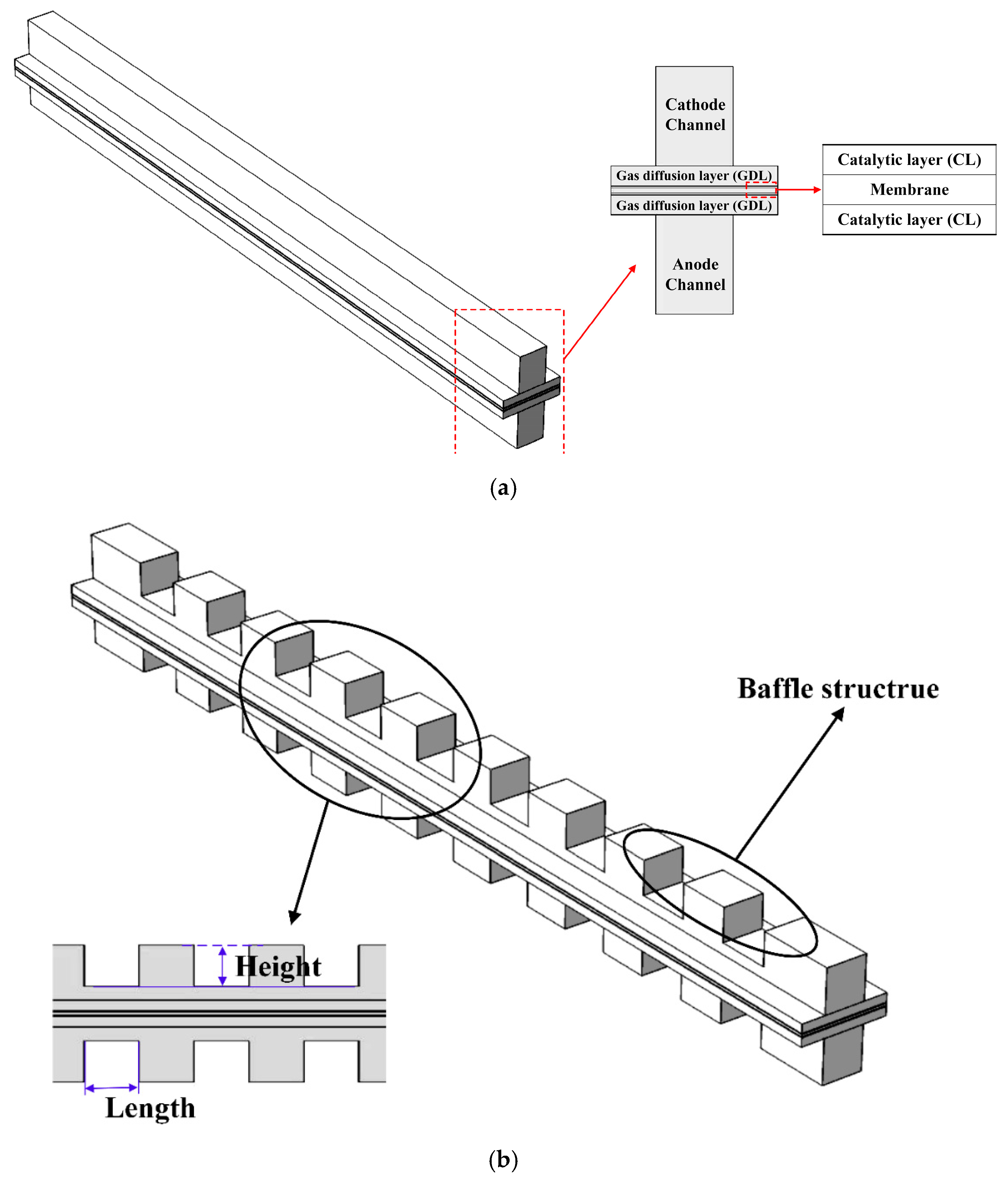
2.1. Physical Model

The computational domain considered in this study is shown in Figure 1a. It consists of an anode/cathode flow channel, gas diffusion layer (GDL), catalytic layer (CL) and membrane. The fuel cell with the baffle structure is shown in Figure 1b. The baffles are added into the flow channels to improve mass transport processes. The number, height and length of baffles are systematically investigated. Reactant gases, namely, hydrogen and oxygen (supplied in the form of air), are, respectively, supplied to the anode and cathode channels. Detailed information on the geometric parameters and operating conditions of the fuel cell can be found in Table 1. Table 2 describes the configuration of the flow channels with baffles.

2.2. Governing Equation

Assumptions: the gas mixture obeys the ideal gas law; the airflow follows fully developed laminar flow; the membrane is impermeable to all gases; the generated water appears in the gaseous state; the porous electrodes are isotropic and homogeneous; it operates in a steady state.
The governing equations and electrochemical equations are described below [37].
Mass equation:
· ρ u = S m a s s
where ρ is the fluid density, u he velocity and Smass is the source term.
Momentum equation:
· ε ρ u u = ε p + · ε μ u + S m o m
where ε is the porosity, p is the fluid pressure, μ is the fluid dynamic viscosity and Smom is the source term.
Energy equation:
ρ c p u · T = · k e f f T + S T
where Cp is the specific heat capacity, T is the temperature, keff is the effective thermal conductivity and ST is the source term.
Species conservation equation:
ρ u · x i = · ρ D i e f f x i + S i
where x is the mass fraction, Deff is the effective diffusion coefficient, S is the source term and the subscript i represents the component.
D i e f f = D i ε τ
where τ represents the tortuosity.
Charge equation:
σ e ϕ e + S e = 0
σ m ϕ m + S m = 0
where σe and σm represent the conductivity of the solid phase and membrane phase, respectively, ϕ e and ϕ m are the potential of the solid phase and membrane phase, respectively, and Se and Sm are the electronic and protonic source terms, respectively.
The Butler–Volmer equations for the anode and cathode can be expressed as follows:
i a = i 0 , a c H 2 c H 2 , r e f 0.5 e n α a F R T η a e n 1 α a F R T η a
i c = i 0 , c c O 2 c O 2 , r e f e n 1 α c F R T η c + e n α c F R T η c
where i0 is the exchange current density, η is the overpotential, C is the molar concentration, F is the Faraday constant and R is the universal gas constant. The transfer coefficients for the anode and cathode are 0.5 and 1, respectively. The subscripts a and c represent the anode and cathode, respectively.
η a = ϕ e ϕ m E e q , a
η c = ϕ e ϕ m E e q , c
where Eeq is the equilibrium potential.

2.3. Boundary Conditions

The outlet boundaries of the anode and cathode flow channels are set as pressure outlets. The electric potential on the surface of the cathode side bipolar plate is set to the operating voltage, while the electric potential on the anode side bipolar plate is set to 0 V.
The inlet flow velocity is calculated based on the stoichiometric ratio, active area and channel dimension.
U a = λ a I 2 F x H 2 R T P A c h a n n e l
U c = λ c I 2 F x O 2 R T P A c h a n n e l
where λ is the stoichiometric ratio, U is the inlet average velocity and A is the cross-sectional area of the channel perpendicular to the direction of fluid flow.
The mole fraction of each component can be determined by the following expressions:
x H 2 O , a 0 = p s a t R H a p a , x H 2 , a 0 = 1 x H 2 O , a . i n , x H 2 , c 0 = p s a t R H c p c , x O 2 , c 0 = 0.21 1 x H 2 O , c 0
where RH is the relative humidity. In this case, it is 100% for both the cathode and anode. Pa and Pc are the reference pressures at the anode and cathode, respectively, with a value of one atmosphere. Psat is the water vapor pressure, and its calculation formula is as follows:
p s a t = 0.61121 e x p 18.678 T 273.15 234.5 T 273.15 257.14 + T 273.15

2.4. Model Validation

Numerical simulations were performed using COMSOL Multiphysics 5.4. To verify the mesh independence, six different numbers of hexahedral meshes were used for the simulation: 18,900, 23,280, 30,160, 50,518, 75,400 and 87,100. As shown in Figure 2a, the relative error in current density for mesh numbers of 50,518 and 87,100 is approximately 0.06%. As the number of meshes increases, the fluctuation in current density becomes minimal. Therefore, considering both computational cost and efficiency, 50,518 mesh elements are selected for the subsequent simulation calculations, and the computational mesh is shown in Figure 2b. Meanwhile, model validation is also carried out. As shown in Figure 3, a favorable consistency is observed between the numerical results and experimental data provided by Ubong et al. [38]. Therefore, the numerical model is reliable.

3. Results and Discussion

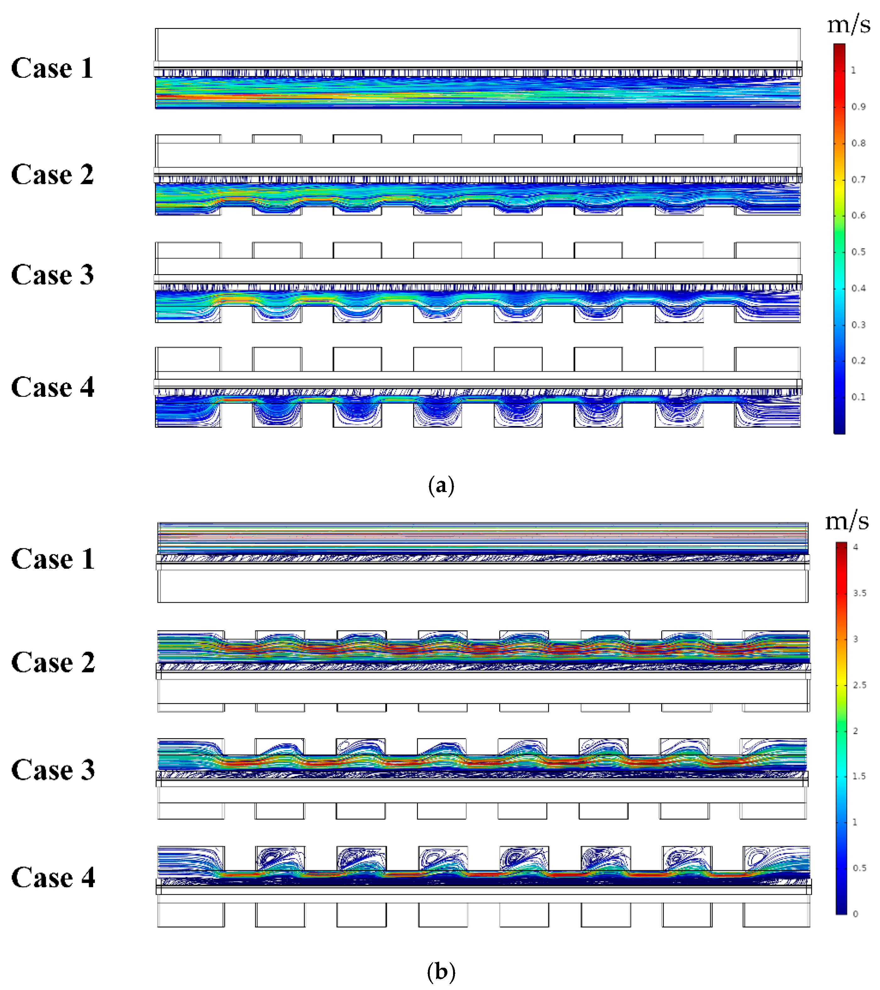
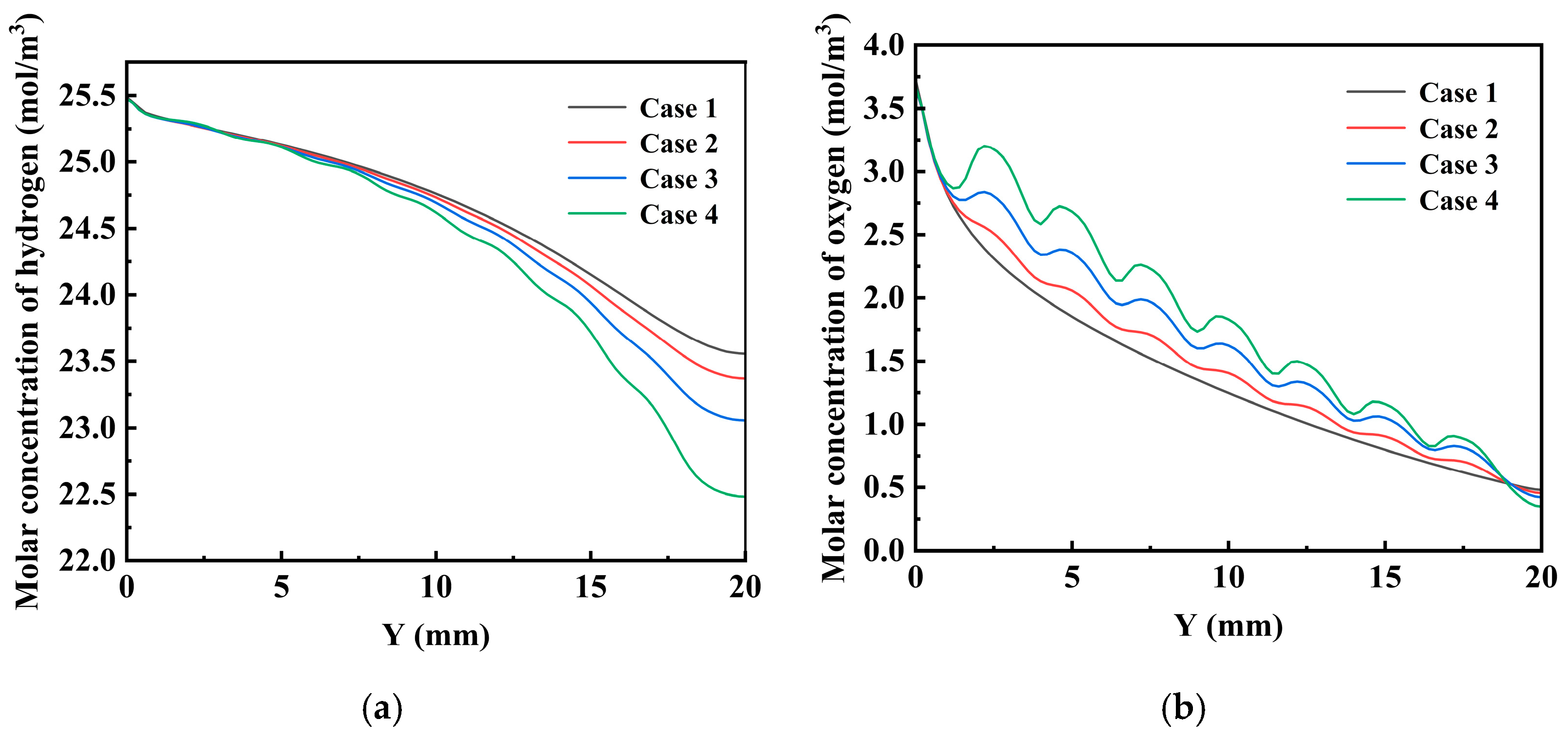
3.1. The Effect of the Height of Baffles

Seven baffles are installed in the flow channel. The four cases are labeled Case 1, Case 2, Case 3 and Case 4, where Case 1 represents the straight channel without baffles, and Cases 2–4 represent the straight channel with baffles. Detailed information of the baffles can be found in Table 2. The baffle heights of Cases 2–4 are 0.25 mm, 0.5 mm and 0.75 mm, respectively. The effect of baffle height on cell performance is shown in Figure 4a. At high and moderate operating voltages, the curves for all four cases almost overlap, and the polarization losses are separately dominated by activation and ohmic losses, indicating that cell performance is not affected by the baffles. However, at low operating voltages, cell performance shows significant changes, and the polarization loss in this region is mainly caused by concentration losses. The baffle structure helps to improve the mass transfer inside the fuel cell. Compared to the conventional straight channel, the performance of the fuel cell with baffles is significantly improved. As the baffle height increases, the current density and output power density gradually increase. At a voltage of 0.4 V, the current densities of Cases 1–4 are 1.390 A/cm2, 1.427 A/cm2, 1.473 A/cm2 and 1.514 A/cm2, respectively. When the baffle height is 0.75 mm, the fuel cell reaches the highest current density. Figure 4b shows that the power density increases with the height of the baffle. The power densities of the cases are 0.556 W/cm2, 0.571 W/cm2, 0.589 W/cm2 and 0.606 W/cm2, respectively. Compared to Case 1, Cases 2–4 are increased by 2.67%, 6.03% and 8.95%, respectively.
Figure 5 shows the pressure drop of the anode and cathode flow channels. The pressure drop is the difference between the inlet and outlet of the flow channel. The baffle height has a great effect on the pressure drop. As the baffle height increases, the pressure drop of the channel also increases. The pressure drop of the cathode flow channel is much higher than that of the anode flow channel. The velocity streamlines of the reactant gases are presented in Figure 6. The baffles have a significant influence on the velocity streamlines. This influence is increased with an increasing baffle height. Meanwhile, the influence on the cathode reactant gas velocity is more significant.
Figure 7 shows the hydrogen and oxygen molar concentration distributions at the GDL and CL interface. The hydrogen and oxygen molar concentrations gradually decrease along the channel direction. The presence of baffles results in variation in species distributions, and the fluctuation increases with baffle height, especially for oxygen distribution. Figure 8 shows the current density contours of different cases. Current density is highest near the channel inlet region, as the reactant gas concentration is the highest. The current density is closely related to the reactant gas concentration. As the electrochemical reactions occur, the reactant concentration decreases, and the current density also drops accordingly.

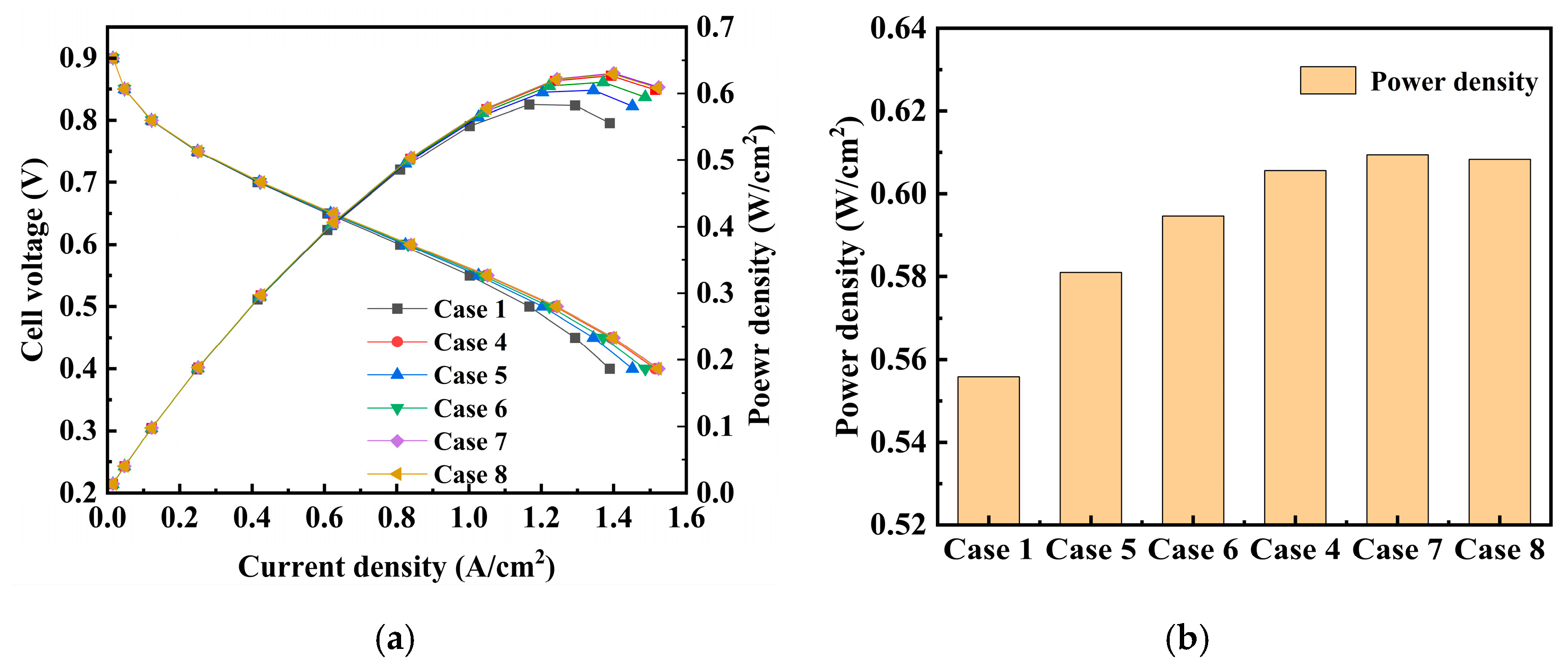
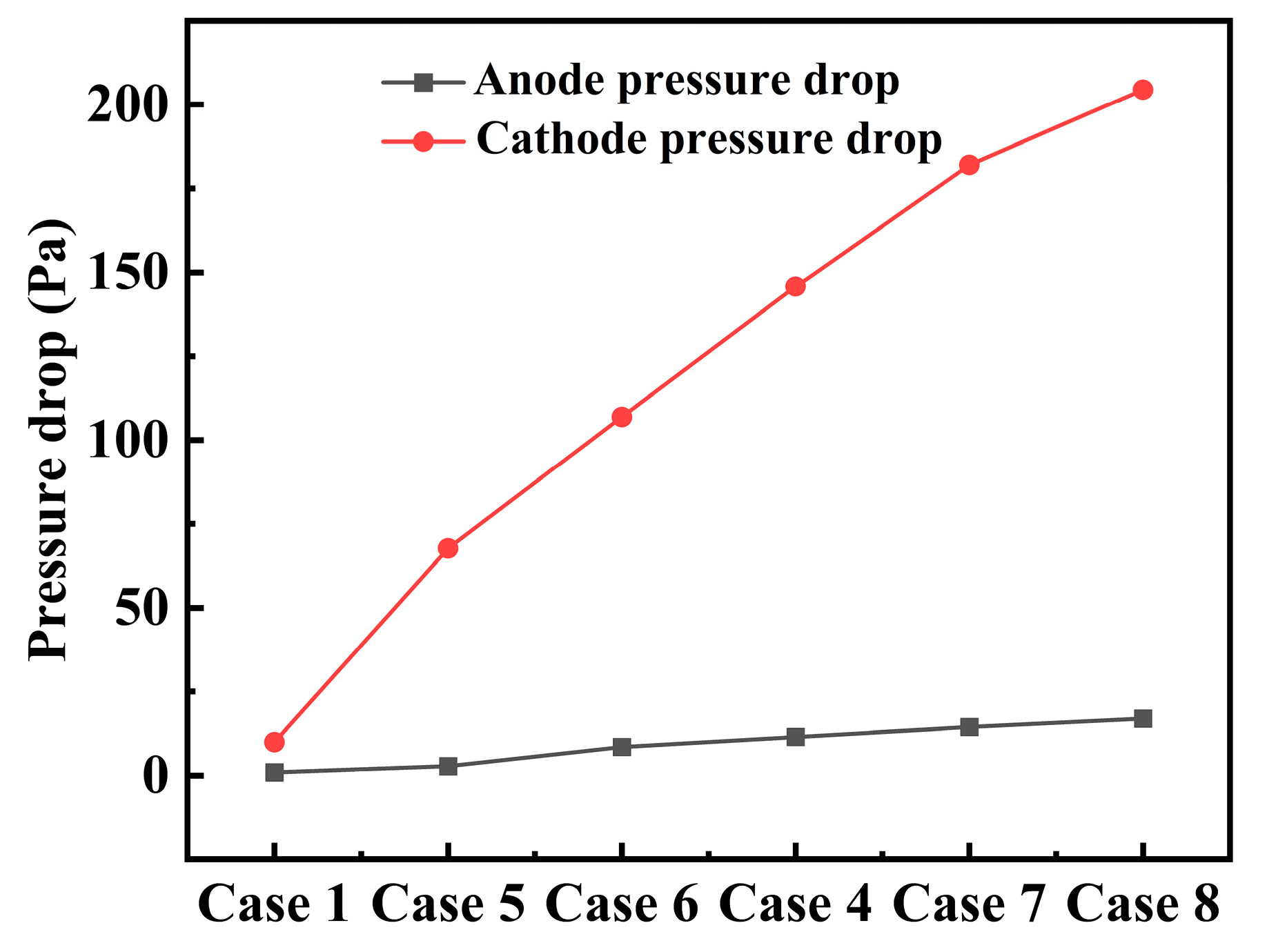
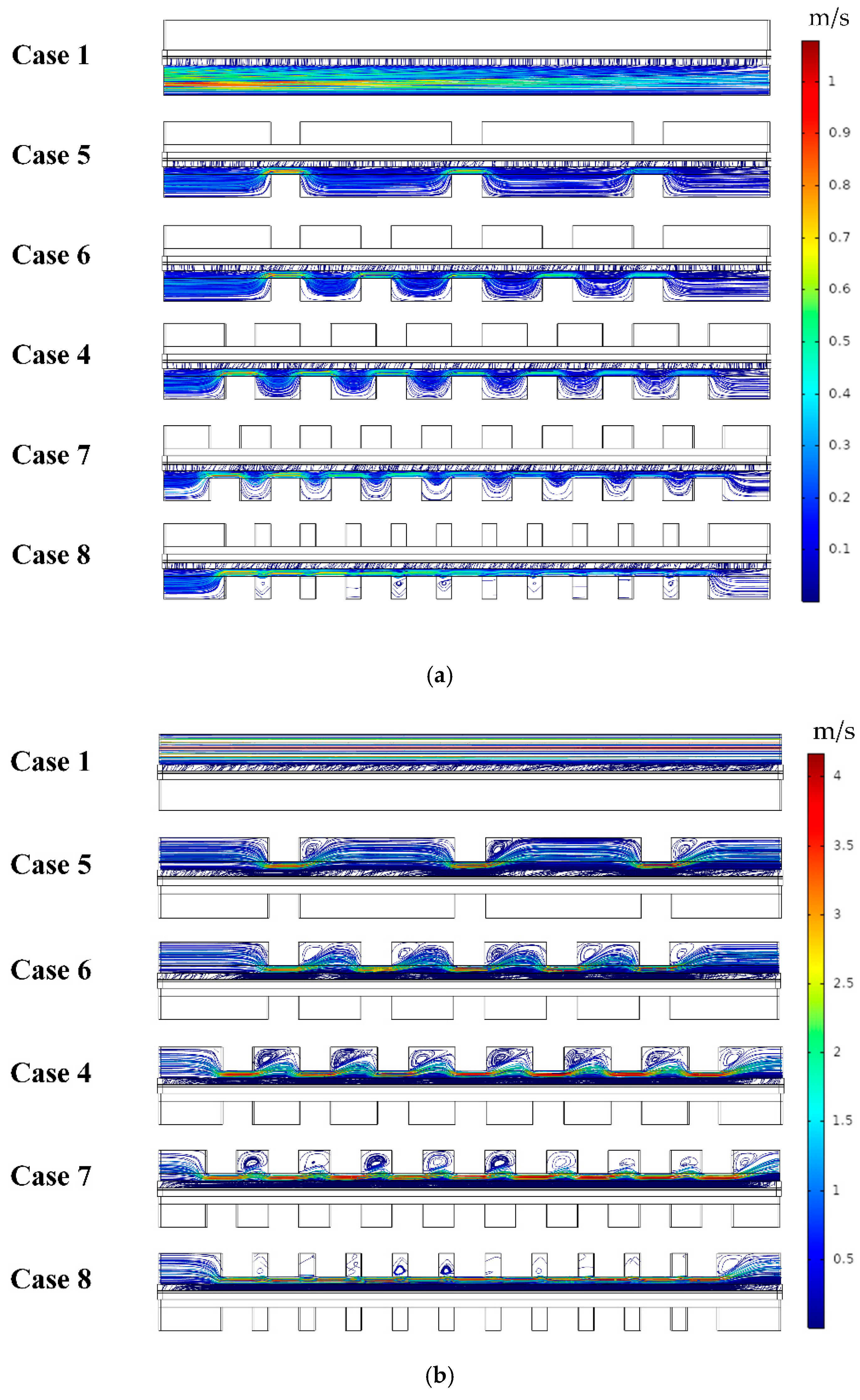
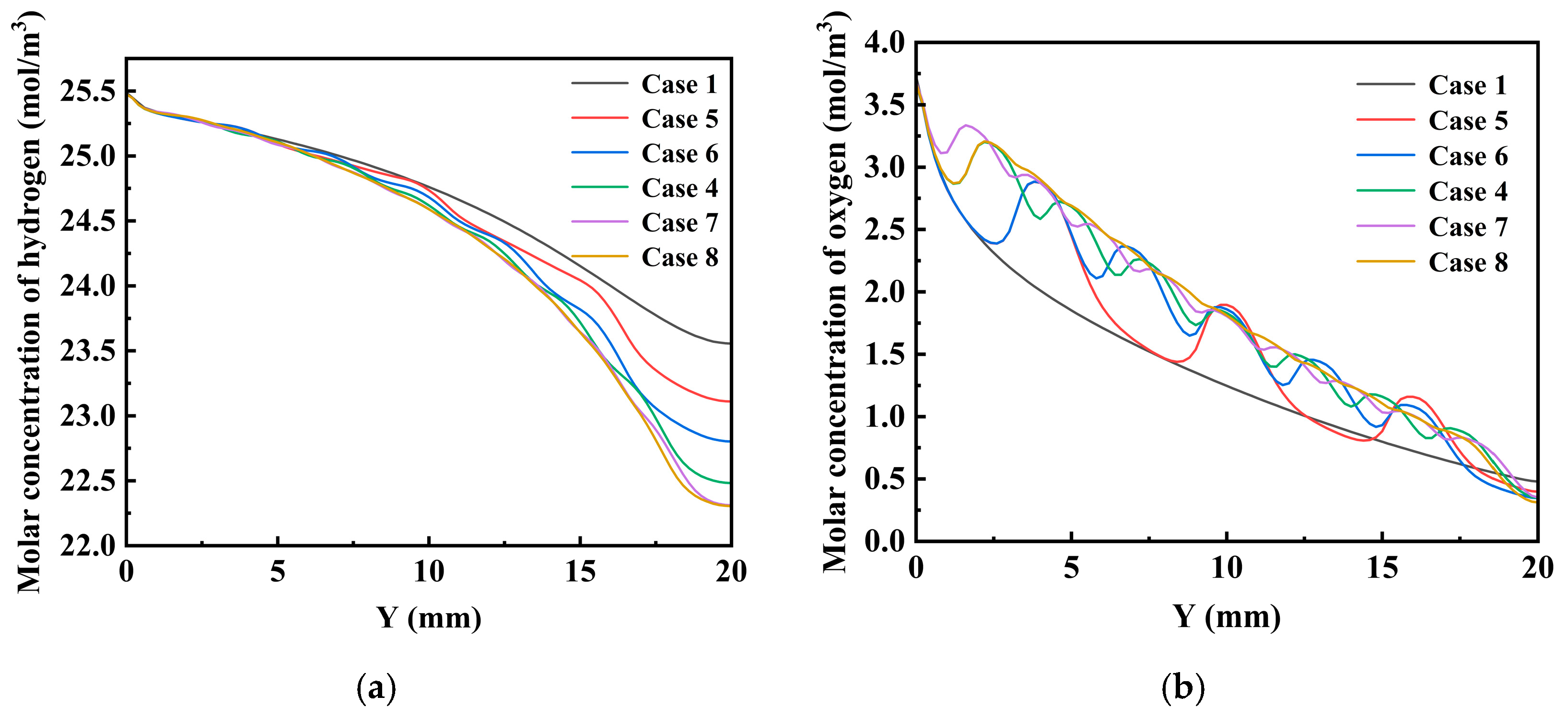
3.2. The Effect of the Number of Baffles

In this section, the baffle height is fixed at 0.75 mm and the effect of the number of baffles on cell performance is studied. The baffle numbers of Cases 5–8 are 3, 5, 9 and 11, respectively. Case 1 is the fuel cell without baffles, and Case 4 is the fuel cell with seven baffles. The effect of the baffle number on cell performance is shown in Figure 9a. The current density of the fuel cell with baffles is higher than that of the fuel cell without baffles. At a voltage of 0.4 V, the current densities of Case 5, Case 6, Case 4, Case 7 and Case 8 are 1.452 A/cm2, 1.487 A/cm2, 1.514 A/cm2, 1.524 A/cm2 and 1.521 A/cm2, respectively. The current density is gradually increased when the baffle number varies from three to nine. However, when the baffle number is increased to 11, the current density is slightly decreased. Figure 9b shows the corresponding power densities. The power densities of Case 5, Case 6, Case 4, Case 7 and Case 8 are 0.581 W/cm2, 0.595 W/cm2, 0.606 W/cm2, 0.609 W/cm2 and 0.608 W/cm2, respectively. Compared to Case 1, the power densities of these cases are increased by 4.52%, 6.97%, 8.95%, 9.64% and 9.44%, respectively. When the baffle number is nine, the fuel cell reaches the highest current density.
Figure 10 shows the effect of the baffle number on the pressure drop of the anode/cathode flow channel. The baffle number has a great effect on the pressure drop. As the number of baffles increases, the pressure drop of the flow channels becomes more pronounced. Similarly, the cathode flow channel pressure drop is much higher than the anode flow channel pressure drop. Figure 11 depicts the velocity streamlines inside fuel cells with different numbers of baffles. As the number of baffles increases, the velocity of the reactant gases near the GDL interface inside the fuel cell channel increases. The baffles alter the direction of the reactant gas flow within the fuel cell channel, allowing more reactant gases to diffuse into the CL, thereby improving cell performance.
Figure 12 shows the effect of the baffle number on the hydrogen and oxygen molar concentration distributions at the GDL and CL interface. The species molar concentration distributions are significantly influenced by the baffle number. The variation in oxygen molar concentration decreases with an increasing baffle number when there are baffles in the flow channels. Figure 13 shows the effect of the baffle number on current density contours. The current density gradually decreases along the channel direction. The baffle number has a significant effect on the current density distributions. The current density becomes more uniform with an increasing baffle number.

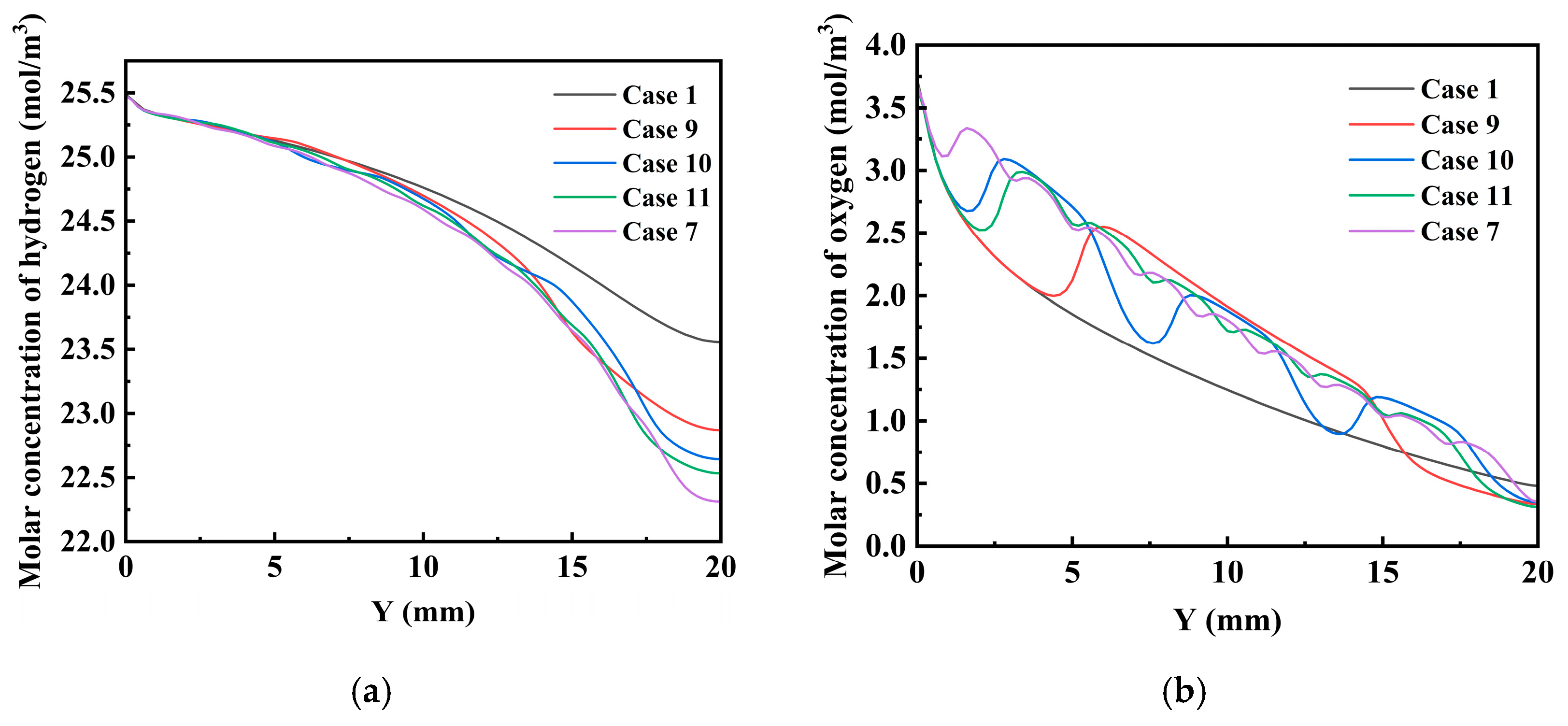
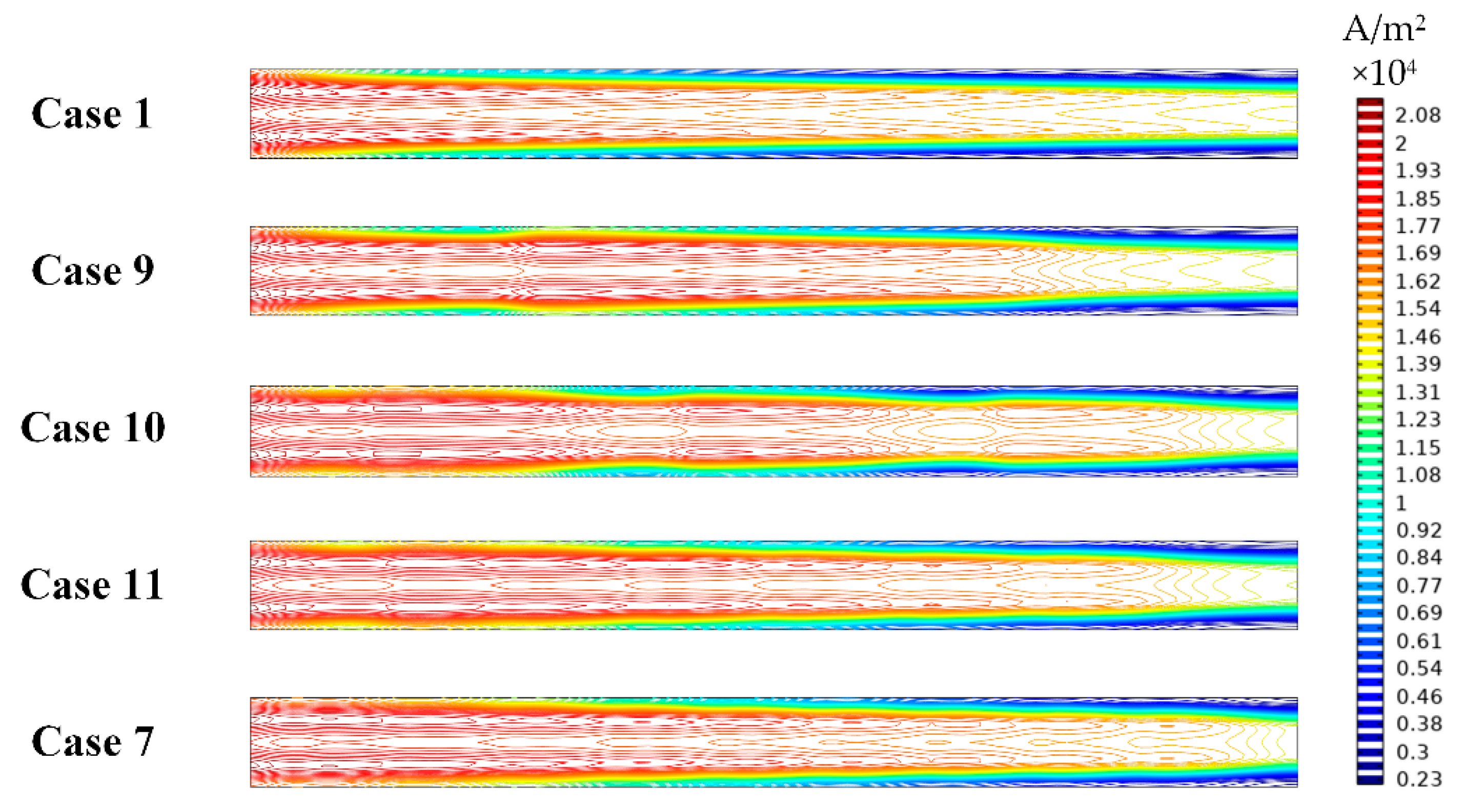
3.3. The Effect of the Length of Baffles

Based on the results of baffle height and number, the optimal performance of the fuel cell occurs when the baffle height is 0.75 mm, the length of each baffle is 1 mm, and the number of baffles is nine. Further investigation is conducted of the effect of baffle length on cell performance. The total baffle length in the flow channel is fixed at 9 mm. The baffle lengths of Cases 9–11 are 9 mm, 3 mm and 1.5 mm, respectively. When the baffle length is increased, the baffle number is decreased. The baffle length of Case 7 is 1 mm. The effect of baffle length on cell performance is shown in Figure 14a. Shorter baffle lengths are associated with better performance. At a voltage of 0.4 V, the current densities of Case 9, Case 10, Case 11 and Case 7 are 1.474 A/cm2, 1.493 A/cm2, 1.503 A/cm2 and 1.524 A/cm2, respectively. Figure 14b shows the corresponding power densities. The power densities of Case 9, Case 10, Case 11 and Case 7 are 0.590 W/cm2, 0.597 W/cm2, 0.601 W/cm2 and 0.609 W/cm2, respectively. Compared to Case 1, the power densities of these cases are increased by 6.10%, 7.47%, 8.19% and 9.64%, respectively.
Figure 15 shows the effect of baffle length on the pressure drop of the anode/cathode flow channel. The pressure drop is greatly influenced by baffle length. Figure 16 depicts the velocity streamlines inside the fuel cells with different lengths of baffles. As baffle length changes, the baffle number also varies. Therefore, the velocity distribution is also significantly affected by baffle length.
Figure 17 shows the effect of baffle length on the hydrogen and oxygen molar concentration distributions at the GDL and CL interface. Baffle length has a significant effect on the hydrogen and oxygen molar concentration distributions. It is observed that a shorter baffle length can promote a more uniform distribution of oxygen within the channel. The effect of baffle length on current density contours is presented in Figure 18. As electrochemical reactions continuously occur within the fuel cell, the reactant gases are gradually consumed, and the current density is decreased accordingly. As baffle length decreases, the distribution of current density becomes more uniform.

4. Conclusions

This paper investigates, in detail, a flow field design to improve cell performance by adding baffles in fuel cell flow channels. The effects of the number, height and length of baffles in the flow channel on transport characteristics and performance are numerically examined. The following conclusions are drawn:
  • The height of the baffle has a significant impact on cell performance. As baffle height increases, current density increases significantly. When the baffle height is 0.75 mm, the current density is at its maximum;
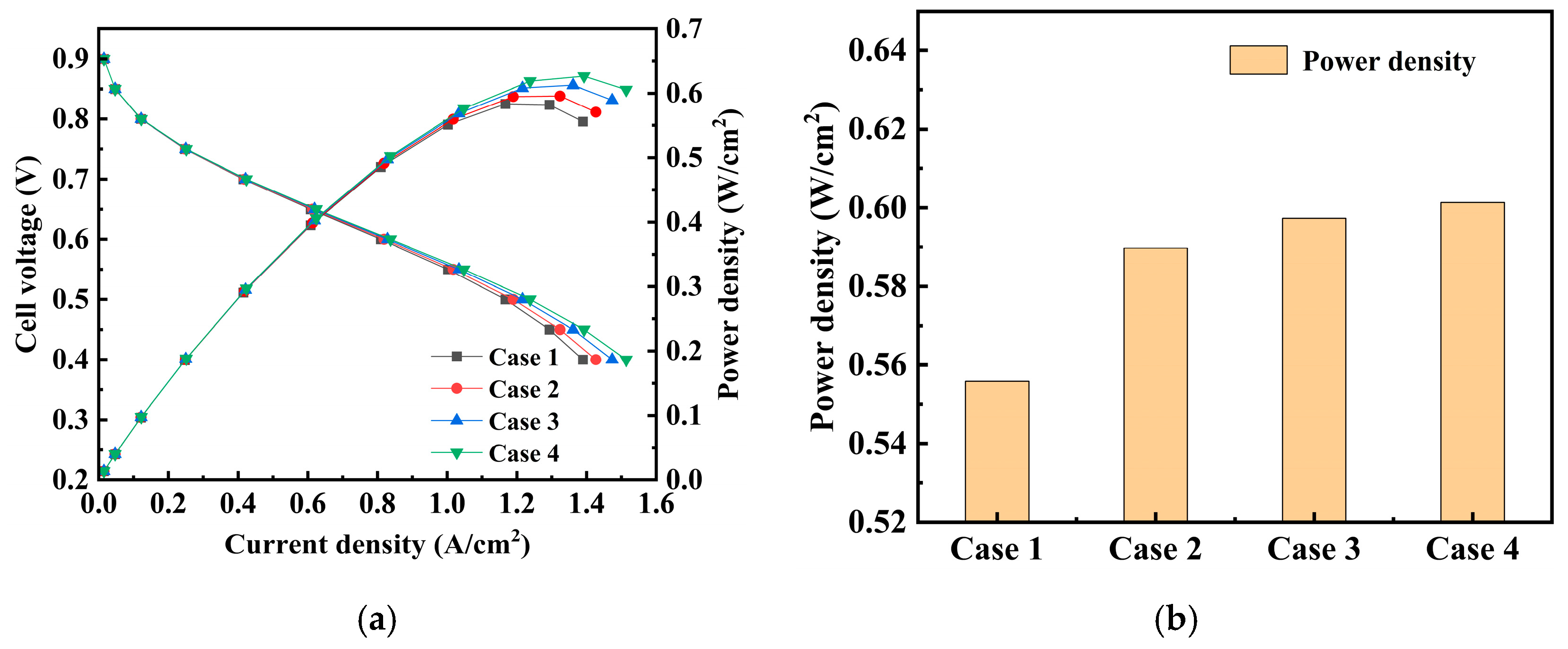
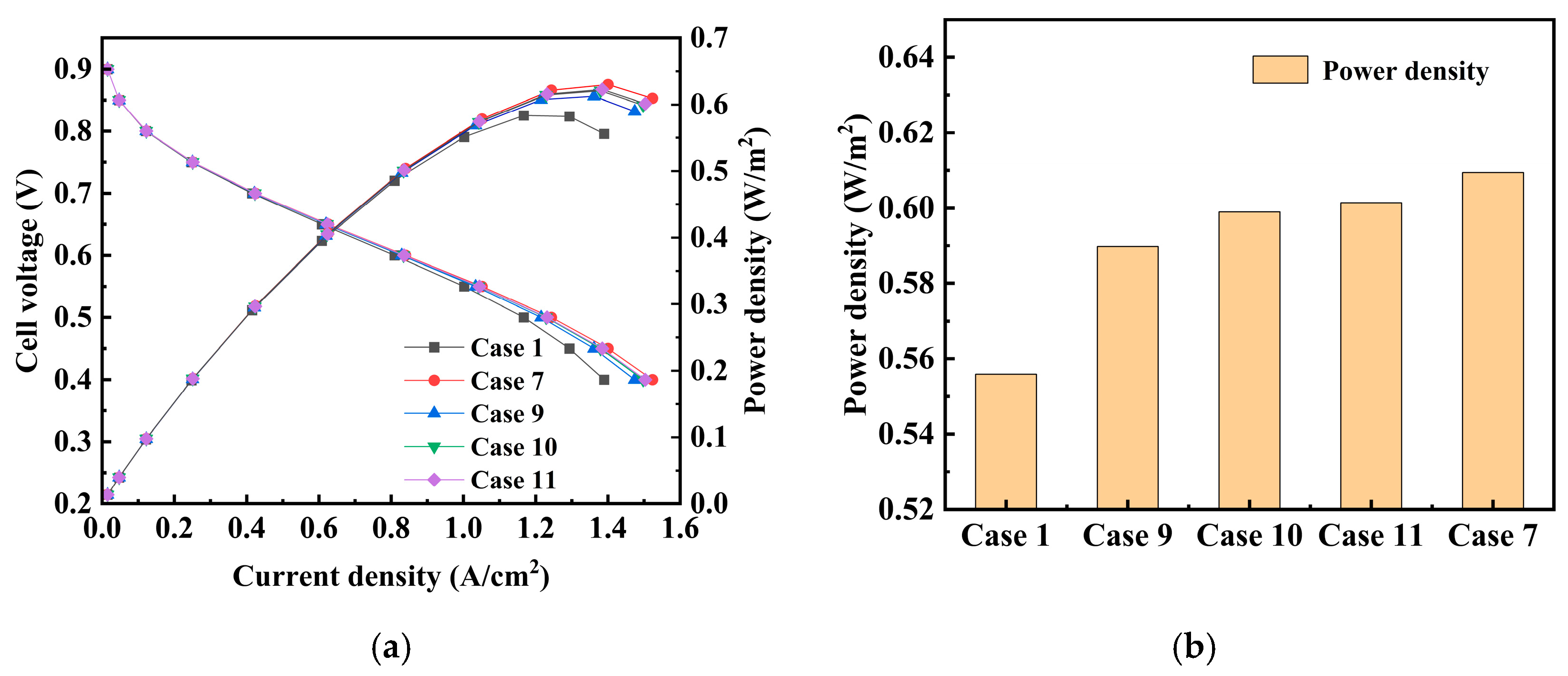
  • When baffle height is fixed, as the number of baffles in the flow channel increases, the current density of the fuel cell shows an upward trend. The best performance is achieved when the number of baffles is 9, but when the number of baffles increases to 11, the performance slightly decreases. Compared to the fuel cell without baffles, the current density is increased from 1.390 A/cm2 to 1.524 A/cm2 at a voltage of 0.4 V. The corresponding power densities are 0.556 W/cm2 and 0.609 W/cm2, respectively;
  • When the total baffle length in the flow channel is fixed, the effect of baffle length on cell performance can be investigated. The length of the baffle also has a significant impact on cell performance. The current density increases with a decreasing baffle length;
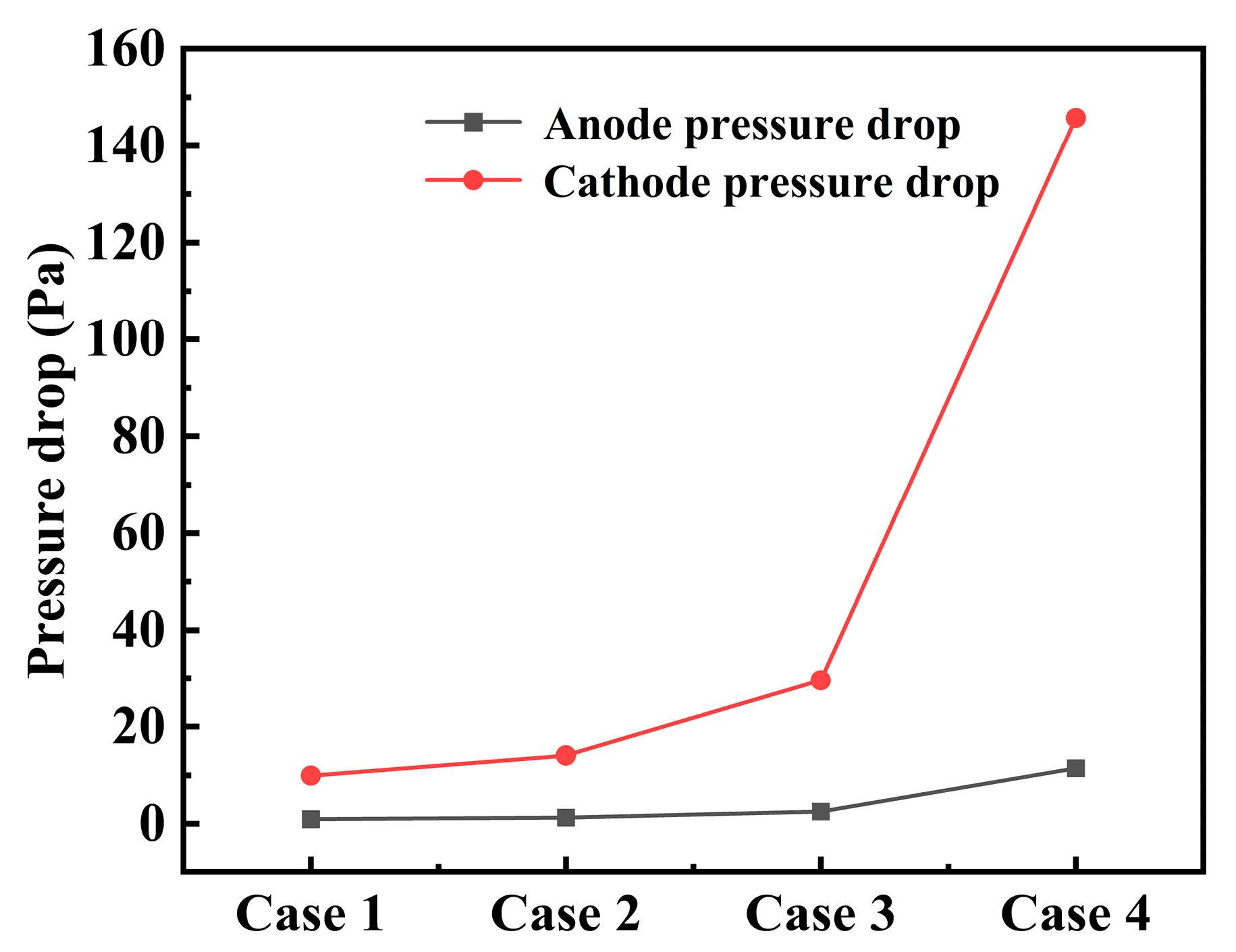
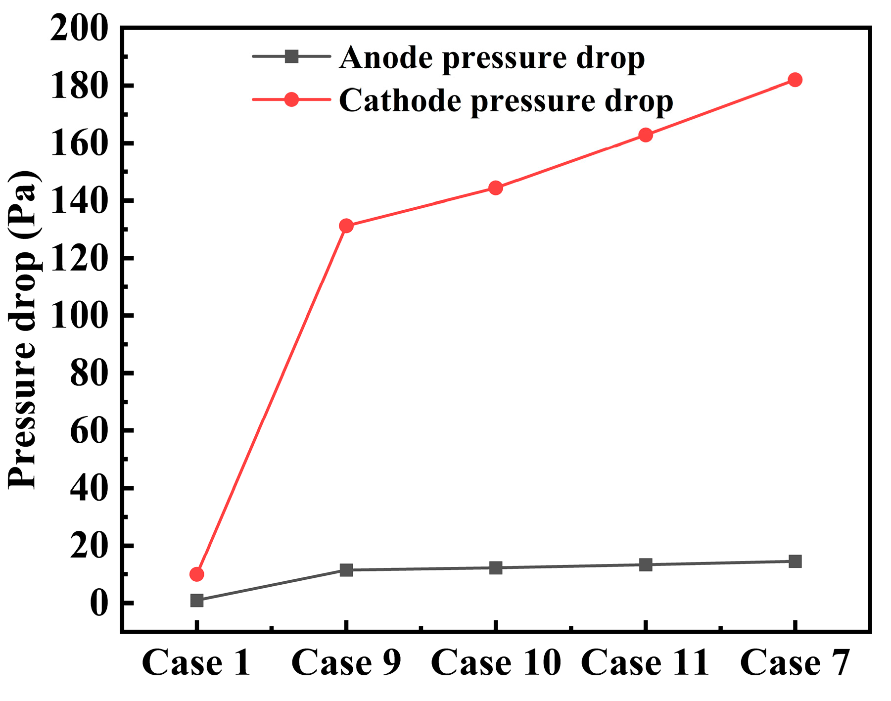
  • The addition of baffles changes the transport phenomena within the fuel cell and increases the current density of the fuel cell as well as the pressure drop of the flow channels. This study can provide guidelines for the flow field design of HT-PEMFCs. In addition, the flow field with baffles can be optimized to maximize cell performance and minimize the pressure drop by using optimization algorithms in the future.

Author Contributions

Conceptualization, S.L., S.Z. and Q.S.; methodology, S.L.; software, S.Z.; validation, S.Z. and S.L.; formal analysis, S.Z.; investigation, S.L.; writing—original draft preparation, S.L. and S.Z.; writing—review and editing, Q.S.; supervision, Q.S.; project administration, S.L.; funding acquisition, S.L. All authors have read and agreed to the published version of the manuscript.

Funding

This research was funded by the National Natural Science Foundation of China, under grant number 52001045, and the National Key R&D Program of China, under grant number 2023YFB4301701.

Institutional Review Board Statement

Not applicable.

Informed Consent Statement

Not applicable.

Data Availability Statement

The original contributions presented in this study are included in the article. Further inquiries can be directed to the corresponding author.

Conflicts of Interest

The authors declare no conflicts of interest.

References

  1. Asadzade, M.; Shamloo, A. Design and simulation of a novel bipolar plate based on lung-shaped bio-inspired flow pattern for PEM fuel cell. Int. J. Energy Res. 2017, 41, 1730–1739. [Google Scholar] [CrossRef]
  2. Siegel, C.; Buder, I.; Heinzel, A. Sectional electrochemical impedance analysis of a high temperature polymer electrolyte membrane fuel cell with three types of flow-fields. Electrochim. Acta 2013, 112, 342–355. [Google Scholar] [CrossRef]
  3. Bayat, M.; Özalp, M.; Gürbüz, H. Comprehensive performance analysis of a high-temperature PEM fuel cell under different operating and design conditions. Sustain. Energy Technol. Assess. 2022, 52, 102232. [Google Scholar] [CrossRef]
  4. Baudy, M.; Rondeau, O.; Jaafar, A.; Turpin, C.; Abbou, S.; Grignon, M. Voltage readjustment methodology according to pressure and temperature applied to a high temperature pem fuel cell. Energies 2022, 15, 3031. [Google Scholar] [CrossRef]
  5. Wang, D.; Ding, X.; Yang, D.; Liang, Z. A novel high current pulse activation method for proton exchange membrane fuel cell. AIP Adv. 2021, 11, 055004. [Google Scholar] [CrossRef]
  6. Zhang, Z.; Bai, F.; He, P.; Li, Z.; Tao, W.Q. A novel cathode flow field for PEMFC and its performance analysis. Int. J. Hydrogen Energy 2023, 48, 24459–24480. [Google Scholar] [CrossRef]
  7. Wu, W.; Zhai, C.; Sui, Y.; Zhang, H. A novel distributed energy system using high-temperature proton exchange membrane fuel cell integrated with hybrid-energy heat pump. Energy Convers. Manag. 2021, 235, 113990. [Google Scholar] [CrossRef]
  8. Bazylak, A. Liquid water visualization in PEM fuel cells: A review. Int. J. Hydrogen Energy 2009, 34, 3845–3857. [Google Scholar] [CrossRef]
  9. Ribeirinha, P.; Abdollahzadeh, M.; Sousa, J.M.; Boaventura, M.; Mendes, A. Modelling of a high-temperature polymer electrolyte membrane fuel cell integrated with a methanol steam reformer cell. Appl. Energy 2017, 202, 6–19. [Google Scholar] [CrossRef]
  10. Sun, H.; Xie, C.; Chen, H.; Almheiri, S. A numerical study on the effects of temperature and mass transfer in high temperature PEM fuel cells with ab-PBI membrane. Appl. Energy 2015, 160, 937–944. [Google Scholar] [CrossRef]
  11. Wu, H.W.; Ku, H.W. The optimal parameters estimation for rectangular cylinders installed transversely in the flow channel of PEMFC from a three-dimensional PEMFC model and the Taguchi method. Appl. Energy 2011, 88, 4879–4890. [Google Scholar] [CrossRef]
  12. Loreti, G.; Facci, A.L.; Ubertini, S. High-efficiency combined heat and power through a high-temperature polymer electrolyte membrane fuel cell and gas turbine hybrid system. Sustainability 2021, 13, 12515. [Google Scholar] [CrossRef]
  13. Nawale, S.M.; Dlamini, M.M.; Weng, F.B. Analyses of the effects of electrolyte and electrode thickness on high temperature proton exchange membrane fuel cell (H-TPEMFC) quality. Membranes 2022, 13, 12. [Google Scholar] [CrossRef]
  14. Mahabunphachai, S.; Koç, M. Fabrication of micro-channel arrays on thin metallic sheet using internal fluid pressure: Investigations on size effects and development of design guidelines. J. Power Sources 2008, 175, 363–371. [Google Scholar] [CrossRef]
  15. Lee, E.K.; Kim, J.K.; Kim, T.J.; Song, H.; Kim, J.H.; Park, S.A.; Jeong, T.G.; Yun, S.W.; Lee, J.; Goo, J.; et al. Enhanced corrosion resistance and fuel cell performance of Al1050 bipolar plate coated with TiN/Ti double layer. Energy Convers. Manag. 2013, 75, 727–733. [Google Scholar] [CrossRef]
  16. Kahraman, H.; Orhan, M.F. Flow field bipolar plates in a proton exchange membrane fuel cell: Analysis & modeling. Energy Convers. Manag. 2017, 133, 363–384. [Google Scholar]
  17. Mohammedi, A.; Sahli, Y.; Moussa, H.B. 3D investigation of the channel cross-section configuration effect on the power delivered by PEMFCs with straight channels. Fuel 2020, 263, 116713. [Google Scholar] [CrossRef]
  18. Qiu, D.; Peng, L.; Yi, P.; Lai, X.; Lehnert, W. Flow channel design for metallic bipolar plates in proton exchange membrane fuel cells: Experiments. Energy Convers. Manag. 2018, 174, 814–823. [Google Scholar] [CrossRef]
  19. Wilberforce, T.; Amiri, A. Comparative study on bipolar plate geometry designs on the performance of proton exchange membrane fuel cells. Fuel 2023, 346, 128389. [Google Scholar] [CrossRef]
  20. Weng, F.B.; Dlamini, M.M.; Hwang, J.J. Evaluation of flow field design effects on proton exchange membrane fuel cell performance. Int. J. Hydrogen Energy 2023, 48, 14866–14884. [Google Scholar] [CrossRef]
  21. Xia, L.; Xu, Q.; He, Q.; Ni, M.; Seng, M. Numerical study of high temperature proton exchange membrane fuel cell (HT-PEMFC) with a focus on rib design. Int. J. Hydrogen Energy 2021, 46, 21098–21111. [Google Scholar] [CrossRef]
  22. Wang, Z.; Wang, H.; Xiao, H.; Bai, J.; Zhao, X.; Wang, S. Enhancing heat dissipation and mass transfer of oxygen gas flow channel in a proton exchange membrane fuel cell using multiobjective topology optimization. Int. J. Hydrogen Energy 2023, 48, 32495–32511. [Google Scholar] [CrossRef]
  23. Hazar, H.; Yilmaz, M.; Sevinc, H. A comparative analysis of a novel flow field pattern with different channel size configurations. Fuel 2022, 319, 123867. [Google Scholar] [CrossRef]
  24. Farokhi, E.; Ghasabehi, M.; Shams, M. Multi-objective optimization of a double tapered flow field Proton Exchange Membrane Fuel cell. Energy Rep. 2023, 10, 1652–1671. [Google Scholar] [CrossRef]
  25. Cai, Y.; Wu, D.; Sun, J.; Chen, B. The effect of cathode channel blockages on the enhanced mass transfer and performance of PEMFC. Energy 2021, 222, 119951. [Google Scholar] [CrossRef]
  26. Karthikeyan, P.; Vasanth, R.J.; Muthukumar, M. Experimental investigation on uniform and zigzag positioned porous inserts on the rib surface of cathode flow channel for performance enhancement in PEMFC. Int. J. Hydrogen Energy 2015, 40, 4641–4648. [Google Scholar] [CrossRef]
  27. Heidary, H.; Kermani, M.J.; Advani, S.G.; Prasad, A.K. Experimental investigation of in-line and staggered blockages in parallel flowfield channels of PEM fuel cells. Int. J. Hydrogen Energy 2016, 41, 6885–6893. [Google Scholar] [CrossRef]
  28. Heidary, H.; Kermani, M.J.; Prasad, A.K.; Advani, S.G.; Dabir, B. Numerical modelling of in-line and staggered blockages in parallel flowfield channels of PEM fuel cells. Int. J. Hydrogen Energy 2017, 42, 2265–2277. [Google Scholar] [CrossRef]
  29. Lobato, J.; Cañizares, P.; Rodrigo, M.A.; Pinar, F.J.; Menta, E.; Úbeda, D. Three-dimensional model of a 50 cm2 high temperature PEM fuel cell. Study of the flow channel geometry influence. Int. J. Hydrogen Energy 2010, 35, 5510–5520. [Google Scholar] [CrossRef]
  30. Taccani, R.; Zuliani, N. Effect of flow field design on performances of high temperature PEM fuel cells: Experimental analysis. Int. J. Hydrogen Energy 2011, 36, 10282–10287. [Google Scholar] [CrossRef]
  31. He, Z.; Luo, X. A Simulation Study on the Optimization of Flow Channel Pattern in High Temperature Proton Exchange Membrane Fuel Cell. J. Phys. Conf. Ser. 2021, 1887, 012005. [Google Scholar] [CrossRef]
  32. Wu, H.W.; Kang, D.Y.; Perng, S.W. Effect of rectangular ribs in the flow channels of HTPEM fuel cell by a three-dimensional model. Energy Procedia 2017, 105, 1376–1381. [Google Scholar] [CrossRef]
  33. Zhang, G.; Guan, Z.; Li, D.; Li, L.; Bai, S.; Sun, K.; Cheng, H. Optimization design of a parallel flow field for PEMFC with bosses in flow channels. Energies 2023, 16, 5492. [Google Scholar] [CrossRef]
  34. Xu, C.; Wang, H.; Cheng, T. Study on the net power density improvement of staggered trapezoidal baffle flow channel for PEMFC. Ionics 2023, 29, 4775–4785. [Google Scholar] [CrossRef]
  35. Perng, S.W.; Wu, H.W.; Chen, Y.B.; Zhang, Y.K. Performance enhancement of a high temperature proton exchange membrane fuel cell by bottomed-baffles in bipolar-plate channels. Appl. Energy 2019, 255, 113815. [Google Scholar] [CrossRef]
  36. Ye, L.; Cheng, X.; Shi, Y.; Li, Z.; Ke, C.; He, Z.; Shi, A. Baffle structure effects on mass transfer and pressure drop of HT-PEMFC with orientated flow channels. AIP Adv. 2024, 14, 015003. [Google Scholar] [CrossRef]
  37. Cheddie, D.F.; Munroe, N.D.H. Three dimensional modeling of high temperature PEM fuel cells. J. Power Sources 2006, 160, 215–223. [Google Scholar] [CrossRef]
  38. Ubong, E.U.; Shi, Z.; Wang, X. Three-dimensional modeling and experimental study of a high temperature PBI-based PEM fuel cell. J. Electrochem. Soc. 2009, 156, B1276. [Google Scholar] [CrossRef]
Figure 1. Schematic of the flow channel: (a) straight channel; (b) channel with baffles.
Jmse 13 00456 g001
Figure 2. (a) Grid independence test; (b) mesh diagram.
Jmse 13 00456 g002
Figure 3. Model validation by comparing polarization curves.
Jmse 13 00456 g003
Figure 4. Effect of baffle height on cell performance: (a) polarization curves and power density curves; (b) power density.
Jmse 13 00456 g004
Figure 5. The effect of baffle height on the pressure drop.
Jmse 13 00456 g005
Figure 6. The effect of baffle height on the streamlines of the velocity distribution: (a) the anode side; (b) the cathode side.
Jmse 13 00456 g006
Figure 7. The effect of baffle height on the molar concentration distribution: (a) hydrogen; (b) oxygen.
Jmse 13 00456 g007
Figure 8. The effect of baffle height on the current density distribution.
Jmse 13 00456 g008
Figure 9. Effect of baffle number on cell performance: (a) polarization curves and power density curves; (b) power density.
Jmse 13 00456 g009
Figure 10. The effect of the baffle number on the pressure drop.
Jmse 13 00456 g010
Figure 11. The effect of the baffle number on the streamlines of the velocity distribution: (a) the anode side; (b) the cathode side.
Jmse 13 00456 g011
Figure 12. Effect of baffle number on molar concentration distribution: (a) hydrogen; (b) oxygen.
Jmse 13 00456 g012
Figure 13. Effect of baffle number on current density distribution.
Jmse 13 00456 g013
Figure 14. Effect of baffle length on cell performance: (a) polarization curves and power density curves; (b) power density.
Jmse 13 00456 g014
Figure 15. Effect of baffle length on pressure drop.
Jmse 13 00456 g015
Figure 16. The effect of baffle length on the streamlines of the velocity distribution: (a) the anode side; (b) the cathode side.
Jmse 13 00456 g016
Figure 17. The effect of baffle length on the molar concentration distribution: (a) hydrogen; (b) oxygen.
Jmse 13 00456 g017
Figure 18. The effect of baffle length on the current density distribution.
Jmse 13 00456 g018
Table 1. Geometric dimensions and physical parameters of fuel cell.
Parameters (Unit)ValueParameters (Unit)Value
Channel length (mm)20Humidified temperature (°C)28
Channel depth (mm)1Fuel cell temperature (°C)180
Channel width (mm)0.7874Operating pressure (atm)1
Rib width (mm)0.90932Cell voltage (V)0.93
GDL thickness (mm)0.2Fuel stoichiometric ratio2.0
CL thickness (mm)0.02Air stoichiometric ratio2.5
Membrane thickness (mm)0.05Anode viscosity (Pa s)1.19 × 10⁻⁵
GDL porosity0.6Cathode viscosity (Pa s)2.46 × 10⁻⁵
CL porosity0.3Inlet H2 mass fraction0.743
GDL conductivity (S/m)222Inlet H2O mass fraction0.023
Membrane conductivity (S/m)9.825Inlet O2 mass fraction0.228
GDL permeability (m2)1.18 × 10⁻¹¹Reference diffusivity of H2 in H2O (m2/s)9.15 × 10−5 (307.1 K)
CL permeability (m2)2.36 × 10⁻¹²Reference diffusivity of O2 in H2O (m2/s)2.82 × 10−5 (308.1 K)
Reference diffusivity of H2O in N2 (m2/s)2.56 × 10−5 (307.15 K)Reference diffusion rate of O2 in N2 (m2/s)2.2 × 10−5 (293.2 K)
Table 2. Different configurations of fuel cells with baffles.
CaseNumberLength (mm)Height (mm)
10
2710.25
3710.5
4710.75
5310.75
6510.75
7910.75
81110.75
9190.75
10330.75
1161.50.75
Disclaimer/Publisher’s Note: The statements, opinions and data contained in all publications are solely those of the individual author(s) and contributor(s) and not of MDPI and/or the editor(s). MDPI and/or the editor(s) disclaim responsibility for any injury to people or property resulting from any ideas, methods, instructions or products referred to in the content.

