Abstract
An increasing demand can be observed in ship-to-ship (STS) liquefied natural gas (LNG) bunkering operations, and the failures involved may lead to considerable casualties or environmental damage. For this purpose, a comprehensive methodology is proposed in this study to identify and assess these failure modes. In detail, the STS LNG bunkering process is first decomposed to develop a hierarchical structure according to systems-theoretic process analysis (STPA), the results of which serve to identify potential failure modes and their causes. Then, all the failure modes are evaluated by experts in terms of occurrence, severity, and detectability to develop a fuzzy confidential matrix, which is then transferred as an explicit confidential matrix to be weighted and normalized. Finally, the risk levels of these failure modes are analyzed by relative closeness obtained from the technique for order preference by similarity to an ideal solution (TOPSIS). This study determines nine failure modes, all of which are ranked in terms of risk level. “High pressure in vapor return line”, and “High flow rate and leakage of LNG” are determined as the top two failure modes, with risk closeness values of 0.5791 and 0.5728, respectively. “Power failure for emergency valves” is ranked as the last one, with the risk closeness value being 0.5444. Finally, suggestions are proposed according to bunkering operation guidelines to prevent or control these failure modes.
1. Introduction
1.1. Background
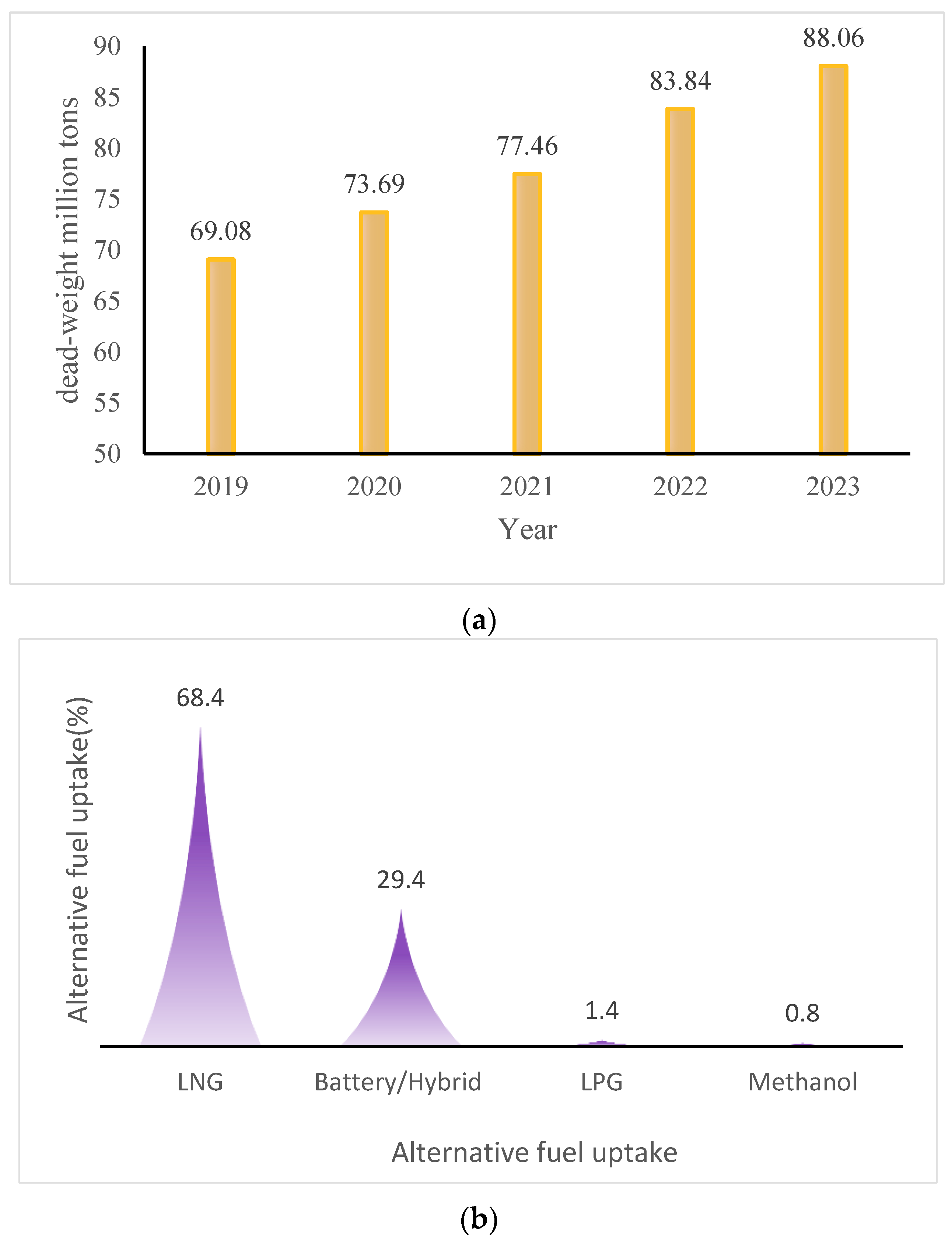
The effective mitigation of energy characterized by heavy carbon emissions is a common concern in international communities and individual countries. The utilization of low-carbon, green, and clear energy has become an irreversible trend in the energy domain under the pressure of achieving carbon emission targets and environmental protection [1]. Natural gas is generally regarded as a competitive alternative energy replacing oil in future energy systems [2]. As is known to all, most of the international natural gas trade is completed through ocean-going ships in the form of liquefied natural gas (LNG). Global seaborne LNG has maintained strong demand in recent years. According to statistics published by the United Nations Conference on Trade and Development (UNCTAD), the total dead weight tons (in millions) of global gas carriers in the last five years is presented in Figure 1a; an increasing trend can be easily observed from 2019 to 2023 [3]. Meanwhile, according to Clarksons Research (2023), the orders for LNG carriers reached 46% of the existing global LNG carrier fleet in May 2023 [4]. In addition, LNG is regarded as a competitive alternative fuel in the maritime domain. To satisfy the requirement of the International Maritime Organization (IMO) in terms of carbon emissions and environmental protection [5], different alternative fuels are offered in the maritime domain, excluding LNG: these are methanol [6], liquefied petroleum gas (LPG) [7], and batteries [8]. According to the investigation conducted by UNCTAD (2023), the practical application of alternative fuels in the maritime shipping domain is presented in Figure 1b, which obviously indicates that the dominant alternative fuel is LNG [3]. Furthermore, the largest share in orders of new-building ships fueled by alternative fuels in 2023 is still LNG fuel [4].
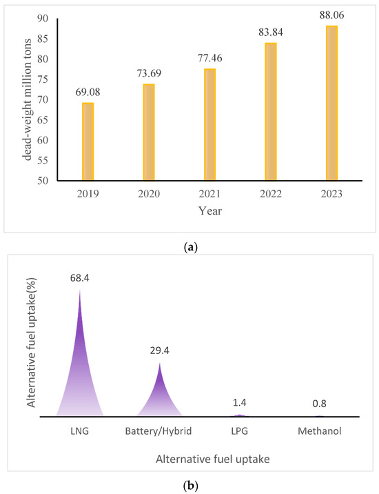
Figure 1.
Global seaborne LNG and alternative fuels in the maritime domain. (a) Dead-weight tons of global gas carriers (2019–2023). (b) Alternative fuel uptake in 2022 (including active fleet and orderbook ships).
The cargo handling associated with LNG carriers is mainly represented by the bunkering or transmission of LNG. Generally, there are three LNG bunkering modes adopted in practical engineering: port-to-ship (PTS), truck-to-ship (TTS), and ship-to-ship (STS) [9]. PTS is usually applicable to the cargo handling of large LNG carriers, while the TTS is suitable for small ports bunkering LNG to ships, especially inland ports. The STS is a kind of flexible mode used to transfer LNG from one ship to another [10], which is adopted in more and more application scenarios, such as bunkering LNG to an LNG-fueled ship, bunkering LNG from a small ship to a larger LNG carrier, and bunkering LNG from a floating liquefied natural gas unit (FLNG) to a shuttle LNG carrier. The above-mentioned scenarios are attributed to normal operations; in the case of emergency situations, the STS mode can also be used to implement the emergency transfer of LNG [11]. Actually, STS LNG bunkering operations are challenging because casualties or significant environmental damage may be caused by the risk events involved in the operational process. The demands for LNG shipping transportation are continuously increasing, which leads to frequent STS LNG bunkering [12]. The flammability of natural gas makes the bunkering operation risky, especially during emergency STS LNG bunkering [13,14]. LNG loading and unloading operations, including STS bunkering, are regarded as having the highest LNG leakage risks according to statistics from the e-MARS database [15]. Therefore, it is necessary to conduct research to assess various risks and propose managerial implications to prevent and control potential failures, which is exactly the purpose of this study.
1.2. Contribution of This Study
To identify the potential failure modes involved in STS LNG bunkering operations, and then propose managerial implications, the STS LNG bunkering operation procedure is first carefully studied with reference to Arnet [16] and Gullberg and Gahnstrom [17]. In addition, the guidelines issued by some communities are also collected in this study, such as IAPH [18], Swedish Marine Technology Forum (SMTF) [19], American Bureau of Shipping (ABS) [20], Korean Register of Shipping (KR) [21], and China Classification Society (CCS) [22]. Then, the operational procedure of STS LNG bunkering is transferred into a hierarchical structure in the present study according to the principle of systems-theoretic process analysis (STPA) to determine all the potential failure modes and their causes. The fuzzy confidential method is applied to evaluate all the identified failure modes in terms of occurrence, severity, and detectability by means of eliciting a group of experts. As a result, a fuzzy confidential structure is developed, which is then transferred into an explicit confidential matrix. Finally, based on the principle of TOPSIS, the explicit confidential matrix is weighted and normalized to calculate the risk levels of different failure modes, based on which managerial implications are subsequently proposed. The innovative contributions of this study are represented as follows.
- (1)
- A comprehensive methodology integrating fuzzy FMEA and TOPSIS is proposed in this study to conduct a risk assessment in the case of an STS LNG bunkering operation, during which the semi-quantitative expert opinion aggregation and quantitative entropy weight method are integrated to achieve as rational results as possible.
- (2)
- The potential failure modes involved in STS LNG bunkering operations are identified, and then their risk levels are quantitatively assessed, the results of which may be helpful for failure prevention in practical engineering.
- (3)
- The results of the risk assessment in this study for STS LNG bunkering operations are analyzed with the safety checklist taken from the STS LNG bunkering operation guidelines. As a result, some managerial implications regarding on-site operations are proposed, which facilitate risk management for simultaneous operations (SIMOPs) during LNG bunkering.
1.3. Organization
The remainder of this paper is organized as follows. The methodology proposed in this study is explained in detail in Section 2. Then, in Section 3, the STS LNG bunkering operational procedure is taken as an example to illustrate the application of the proposed methodology, and the findings and extended discussions are presented in Section 4. Finally, the paper is concluded in Section 5.
2. Literature Review
Risk management and failure prevention are core components of LNG bunkering, especially for the STS mode. As a result, risk analysis for LNG bunkering operations has attracted much attention from both scholars and practitioners recently. Vairo et al. [23] investigated operational perturbations during the LNG bunkering process by integrating dynamic Bayesian network and Markov models; a similar time-varying BN was also applied by Fan et al. [24] to capture dynamic risks involved in simultaneous LNG bunkering operations; and Wu et al. [25] studied the causal relationship of LNG risks by means of a dynamic BN. Fan et al. [26] reviewed and summarized the risk analysis methods for LNG bunkering simultaneous operations, the reliability of which was also emphasized by Uflaz et al. [27], who investigated the operational reliability during the STS LNG bunkering process. Similarly, Vairo et al. [28] proposed a resilience model to improve the reliability of LNG bunkering operations. Obviously, operational risks caused by human-related factors are also the concern of many scholars in maritime risk analysis [29]; similar studies in the field of LNG bunkering include Stokes et al. [30], Wu et al. [25], and Fan et al. [31]. In addition, there are many studies focusing on LNG leakage risk assessment, the determination of safety distances, and boil-off gas (BOG) management for risk assessment regarding LNG bunkering.
- (1)
- LNG leakage risk assessment. The causes contributing to leakage during LNG bunkering were investigated by Arnet [16] with traditional risk analysis tools, and Gerbec and Aneziris [32] comprehensively analyzed the risks involved in bunkering arms and hoses during LNG bunkering by means of a literature review. Nubli et al. [33] analyzed the consequences of accidental LNG leakage for bunkering ships, and later, this accidental LNG leakage was also investigated in terms of its consequence by Nubli et al. [9] about the cryogenic risk on the hull structure. Zhang et al. [34] conducted a risk assessment for the leakage risk of STS LNG bunkering by fuzzy Bayesian network (FBN). Furthermore, small-diameter leaks were modeled by Lim and Ng [35] using computational fluid dynamics (CFD) simulation, which was also applied by Nguyen et al. [36] to analyze the influence of external factors on the LNG leakage.
- (2)
- Determination of safety zone. The methods to establish a safety zone during STS LNG bunkering operations have been comprehensively reviewed by Duong et al. [37]. Accidental release during LNG bunkering is the main factor considered to determine the safety zone [38], and according to Jeong et al. [39], the safety exclusion zones for LNG bunkering were also practically influenced by the number of operators on-site; furthermore, Park et al. [40] tried to identify various factors affecting the design of safety zone during LNG bunkering. Park and Paik [41] proposed a methodology to design the safety zone for TTS LNG bunkering operations. Similarly, the safety zone for another LNG bunkering process scenario for a floating LNG-fueled power plant was designed earlier by Park et al. [42]. Jeong et al. [43] took an LNG carrier as an example to discuss the establishment of a safety zone by analyzing potential LNG gas dispersion; for a similar study, the reader can also be referred to Duong et al. [44].
- (3)
- BOG management. For LNG bunkering operations, the BOG is inevitable due to heat ingress; the BOG generation in the receiving tanks at the beginning of the bunkering operation is mainly due to to heat ingress within the bunkering pipelines [45]. According to Benito [46], the generation of BOG during LNG bunkering is approximately 8–10 times more than that generated during storage. As a result, STS LNG bunkering operations were greatly challenged by effective BOG management according to Lee et al. [47]. Shao et al. [48] found that the BOG generated in the receiving tanks directly increase the pressure, which was greatly induced by the temperature difference between the receiving tank and the bunkering tank; later, Shao et al. [49] proposed a method to suppress BOG by optimizing the bunkering time. Meanwhile, Kim et al. [50] also addressed this issue by proposing an energy storage system on LNG bunkering ships.
According to the abovementioned literature, the previous studies are mainly focused on specific aspects, such as LNG leakage risks, safety zone design, and BOG management, the results of which are beneficial to control some specific risks. However, there are many potential risks or failures involved in the LNG bunkering operation, and in many cases, the risks may be different under different failure modes. Based on the literature review aforementioned, there are few studies focusing on the identification and evaluation of potential failure modes and their risk factors. In addition, it can be observed that LNG leakage is frequently studied, and various risk factors are identified and evaluated by scholars. In fact, most LNG leakage is practically caused by human-related factors, which are paid little attention in the previous studies; the human-related operational risks involved in the LNG bunkering process are addressed in this study. Furthermore, although studies about risk assessment for LNG bunkering operations can be found, these risk assessment works pay little attention to the potential failure mode involved in the bunkering process. This study takes a more comprehensive approach by evaluating the entire STS LNG bunkering process.
Failure mode and effect analysis (FMEA) has recently attracted broad attention in the maritime domain. FMEA analysis is focused on quantifying the risk priorities of different failure modes by considering the occurrence, severity, and detectability of each failure mode [51]. Essentially, FMEA is widely regarded as a qualitative approach; to compensate for its shortcomings in terms of quantitative analysis, some scholars integrate different quantitative tools into FMEA to conduct a maritime risk assessment. For instance, Bayesian networks (BNs) were combined with FMEA by Park et al. [52] and Wan et al. [53] to assess maritime cybersecurity risks and maritime supply chain risks, respectively. Liu et al. [54] embedded an expert trust network into the FMEA framework to investigate the risks involved in the maritime oil spill. In addition, Liu et al. [55] integrated probabilistic double hierarchy linguistic term sets into FMEA to assess maritime risks involved in the development of the marine economy. In the field of LNG bunkering, Kang et al. [56] investigated the accidental LNG leakage in the scenario of offshore transfer and delivery system by CFD method based on the principle of FMEA. Another important improvement of the traditional FMEA method is the use of fuzzy expert systems. Goksu and Arslan [57] proposed a rule-based fuzzy FMEA to study the risks involved in ship berthing/unberthing operations. Similar studies include Ceylan et al. [58] and Ceylan [59]. In addition, the fuzzy FMEA method was applied by Akyuz and Celik [60] and Akyuz [61] to analyze the oil spill risks and the hatch cover failures, respectively. As discussed above, the FMEA successfully identifies the potential failure modes and their causes. However, the shortcomings of FMEA are also obvious [62,63]. The technique for order preference by similarity to an ideal solution (TOPSIS) is considered a rational technology to overcome the shortcomings of FMEA [7], especially for the scenario of being characterized by high uncertainty, such as the application scenario studied in this study (STS LNG bunkering); fuzzy TOPSIS is applicable [64]. In addition, the FMEA-based TOPSIS method has been applied by Bashan et al. [65] in the maritime domain to identify various risk factors involved in the navigation process.
The abovementioned studies have well verified the applicability and superiority of the FMEA method in the maritime domain, and FMEA is characterized by great potential to be extended to LNG bunkering risk assessment. The results of the literature review about risk assessment for LNG bunkering operations show that the existing methods are mainly focused on some typical failure modes, such as LNG leakage and the design of safety zones; few studies have addressed a risk assessment covering all operational processes. In addition, due to the operational data about the STS LNG bunkering being limited, previous studies on LNG bunkering risk assessment have mainly been conducted by means of expert elicitation, which essentially is a subjective approach. In this study, the objective entropy-based weight is also considered to eliminate the objective influence to some extent. Therefore, in the present study, the fuzzy confidential method and TOPSIS are integrated into the traditional FMEA to improve the performance of traditional FMEA, the results of which are aimed at improving the safety management for STS LNG bunkering operations.
3. Principle of the Methodology
3.1. Overview of the Methodology
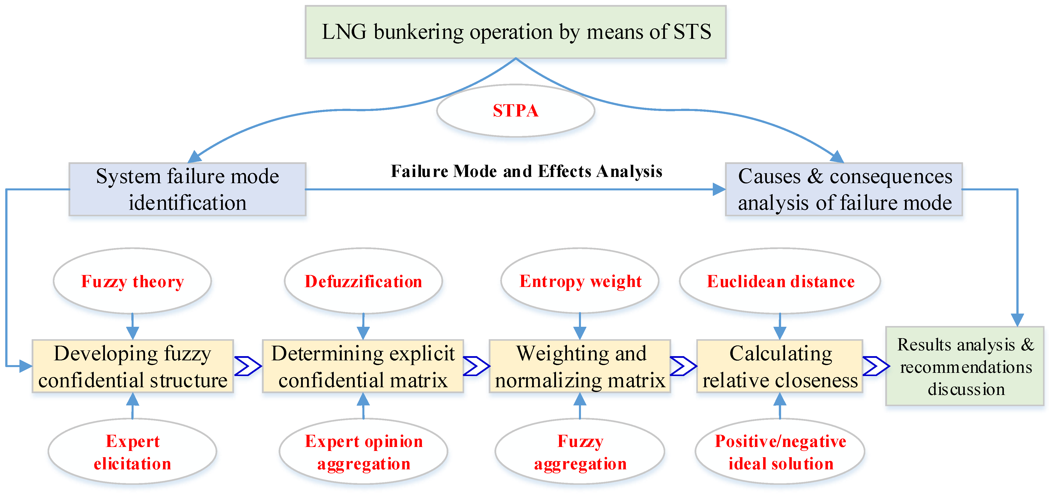
The comprehensive methodology proposed in this study is presented in Figure 2, which can be generally divided into two parts. The first part is mainly focused on the integration of STPA and FMEA. In detail, the output of STPA is used to model the FMEA; for this purpose, the operational scenario of the STS LNG bunkering process is modeled according to the principle of STPA, the results of which serve as the input of FMEA. For instance, some unsafe control actions may be considered as failure modes in the FMEA. The second part of this methodology is to quantitatively analyze the developed FMEA with the help of fuzzy theory and the TOPSIS method, which is the main body of this study. The fuzzy theory is mainly used to assess the occurrence, severity, and detection of each failure mode in the FMEA because the data volume of the STS LNG bunkering operation is too small to conduct risk assessment. In addition, the TOPSIS method is used in this study to quantify the comprehensive influence of occurrence (O), severity (S), and detectability (D) regarding the failure modes, which is more reasonable than the traditional practice of just multiplying O, S, and D [7,50].
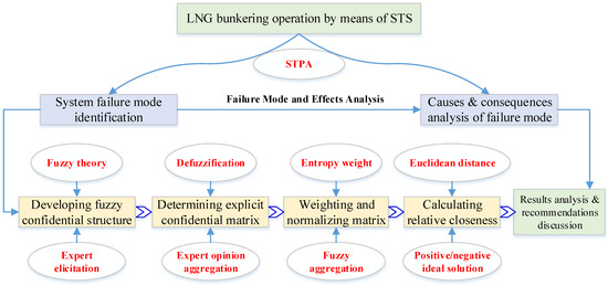
Figure 2.
Overview of the proposed methodology.
3.2. Fuzzy FMEA Modeling
3.2.1. Failure Mode Analysis of STS LNG Bunkering Operations by STPA
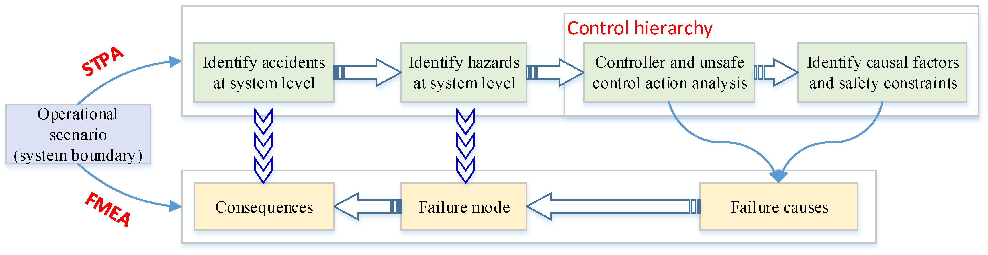
To identify the failure modes, failure causes, and consequences of the STS LNG bunkering operations, STPA is applied to describe qualitatively the operation process, based on which to model the FMEA. The general principle of mapping STPA into FMEA is illustrated in Figure 3.
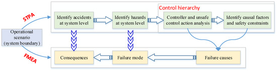
Figure 3.
General principle of mapping STPA into FMEA.
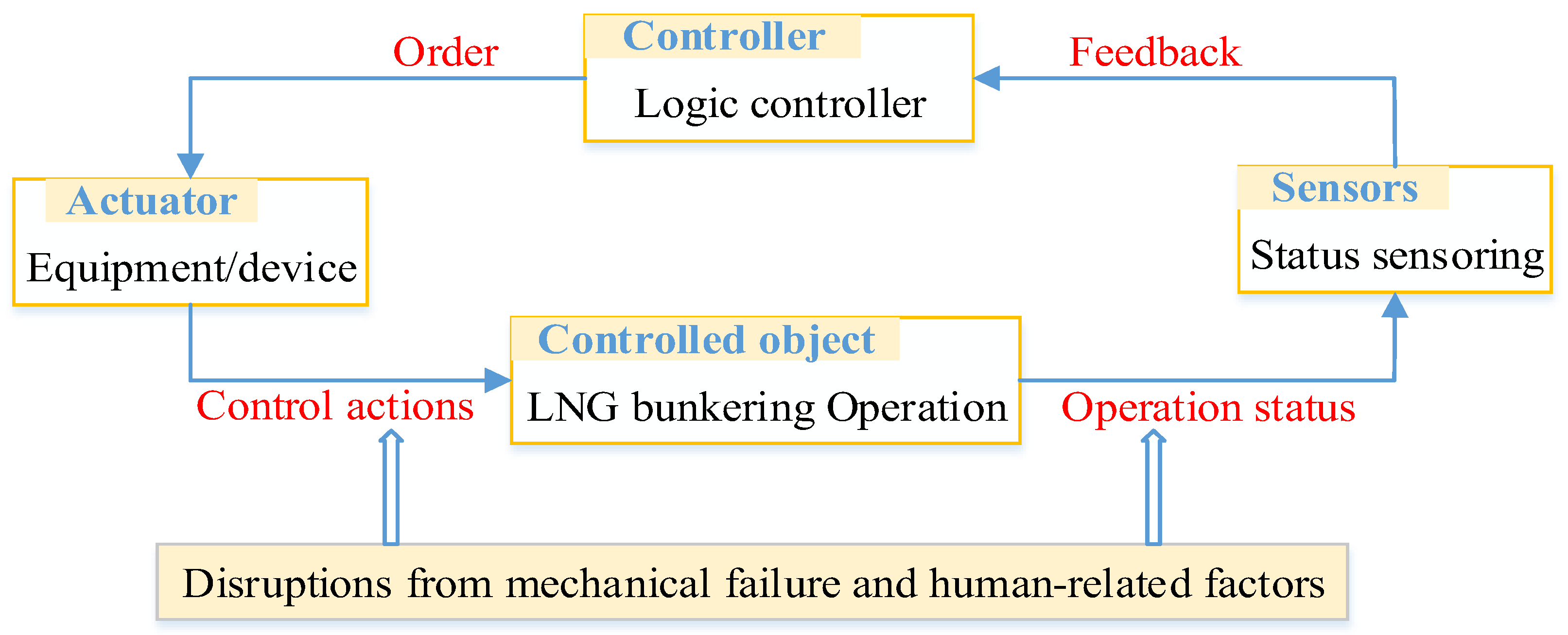
According to Figure 3, the operational scenario of the STS LNG bunkering process comes first to determine the system boundary and the components involved in the bunkering operation. Then, according to the basic principle of STPA [66,67], the bunkering operation is analyzed qualitatively at the system level and operational level. At the system level, the objective is to identify the potential accidents and major hazards, both of which correspond to the consequences and failure modes, respectively, under the framework of FMEA. When it comes to the operational level, the hierarchical safety control structure is extracted on the basis of the bunkering operation process, which is a critical content of the STPA [68]. To develop the safety control structure, the controllers, controlled bodies, actuators, and sensors are identified to establish a loop—various disruptions from the external environment may affect this loop, such as mechanical failures and human-related factors—which is conducted according to Figure 4.
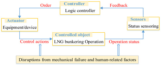
Figure 4.
Control hierarchy of the STPA analysis.
The unsafe control actions stem from the following four aspects, according to Qiao et al. [67]: safe control actions are absent, some risks may be involved in the control actions, the control actions are provided inappropriately in terms of time or sequence, and the duration of the control actions is improper. The causation analysis for the unsafe control actions is crucial for the safety constraint; these causes may be involved in the abovementioned controllers, actuators, and sensors. The results stemmed from the unsafe control actions and their causes contribute to the failure causes under the framework of FMEA.
3.2.2. Development of Fuzzy Confidence Structure
In this study, a group of maritime experts were employed to give their professional judgment regarding the identified failure modes. For this purpose, fuzzy theory was applied to facilitate the expert elicitation, and presenting the qualitative expression of experts in the form of the corresponding fuzzy numbers was critical to obtaining meaningful information. Based on the methodology proposed by Chen and Hwang [69], five verbal terms were used to conduct expert elicitation, and they are VL (Very low), L (Low), M (Medium), H (High), and VH (Very high) [29]. As a result, the evaluation set containing fuzzy linguistic expressions is presented as
However, when it comes to the operational process of LNG bunkering, in many cases, professional maritime experts may not be able to explicit judgment due to their knowledge limitation. Therefore, it is necessary to introduce some linguistic expression between the neighboring verbal terms; for instance, a judgment may be between VL and L, which is represented by . As a result, another group of fuzzy linguistic variables is also contained in the evaluation set: , , and .
The trapezoidal fuzzy number is applied, and the relationships between the explicit fuzzy judgment and trapezoidal fuzzy number are listed in Table 1, which is used to collect the professional judgment in terms of Occurrence, Severity, and Detection.

Table 1.
Fuzzy linguistic variables used in this study.
In addition, the abovementioned fuzzy variables of , , and correspond to trapezoidal fuzzy numbers of (0,1,2,3), (2,3,4,5), (4,5,7,8), and (7,8,9,10). In this study, maritime professional experts were employed to evaluate each failure mode involved in the LNG bunkering operation in terms of O, S, and D, and the results are represented by the following fuzzy belief structure,
where is the th failure mode, denotes the O (), S (), and D (), respectively; is the confidential given by the th expert with the objective of a fuzzy variable . Some cases are given as examples to illustrate the application of the fuzzy belief structure when it comes to expert elicitation.
- (1)
- If an expert’s judgment is a certain linguistic expression for sure, such as L, then the confidential structure is expressed as ;
- (2)
- If an expert’s judgment is uncertain between two adjacent linguistic expressions, such as between VL and L, and the probability of VL is 70%, while the probability of L is 30%, then the confidential structure can be expressed as .
- (3)
- Another uncommon case is presented as when the expert’s judgment is between two adjacent linguistic expressions without probability, such as the evaluation result being between VL and L; in this case, the confidential structure is expressed as .
The evaluation results of the failure mode in terms of from all the maritime professional experts can be summarized and represented by
where is the fuzzy comprehensive confidential structure, and is the comprehensive confidential of in terms of , which is valued by
where is the weight of the th expert, and the sum of is equal to 1.
3.2.3. Determining the Weights of Experts
Expert elicitation is an effective way for the situation of this study where the data about the failure mode of LNG bunkering operation are difficult to be obtained. The competence of the employed experts is critical for the correct results [70], and the selection criteria can be referred to Qiao et al. [29]. Furthermore, to eliminate the potential biases, the expert team is heterogeneous in this study. After selecting the experts, the capacity of these experts is evaluated to obtain their weights. For this purpose, several indicators for professional capacity and the score rating should be established. Then, pairwise comparison matrices are developed on the basis of capacity comparison between two experts in terms of the determined capacity indicators. Finally, the weights for these experts are determined by processing the developed matrices [29], and the calculation process is presented as follows.
- (1)
- Pairwise comparisons among these experts are conducted in terms of the evaluation indicators, the results of which are presented as pairwise comparison matrices; for instance, the results of pairwise comparisons in terms of the th evaluation indicator can be denoted by , which is presented aswhere denotes the comparison result between the th expert and the th expert, expressed by a fuzzy number. Actually, is a symmetrical matrix with diagonal elements being equal to 1.
- (2)
- The synthetic pairwise comparison matrix for these experts is then established on the basis of pairwise comparison matrices , and the results are presented aswhere denotes the number of experts, and can be obtained bywhere is the element in the pairwise comparison matrices, and denotes the number of evaluation indicators.
- (3)
- The geometric mean method is used to obtain fuzzy weights of the indicators for each expert, which are calculated by
- (4)
- The fuzzy weight of each expert is defined as follows,where denotes the fuzzy weight of the th criterion.
- (5)
- The weight of the th expert can be obtained using the center of area method, which is expressed as,
3.3. Defuzzification to Obtain an Explicit Confidential Matrix
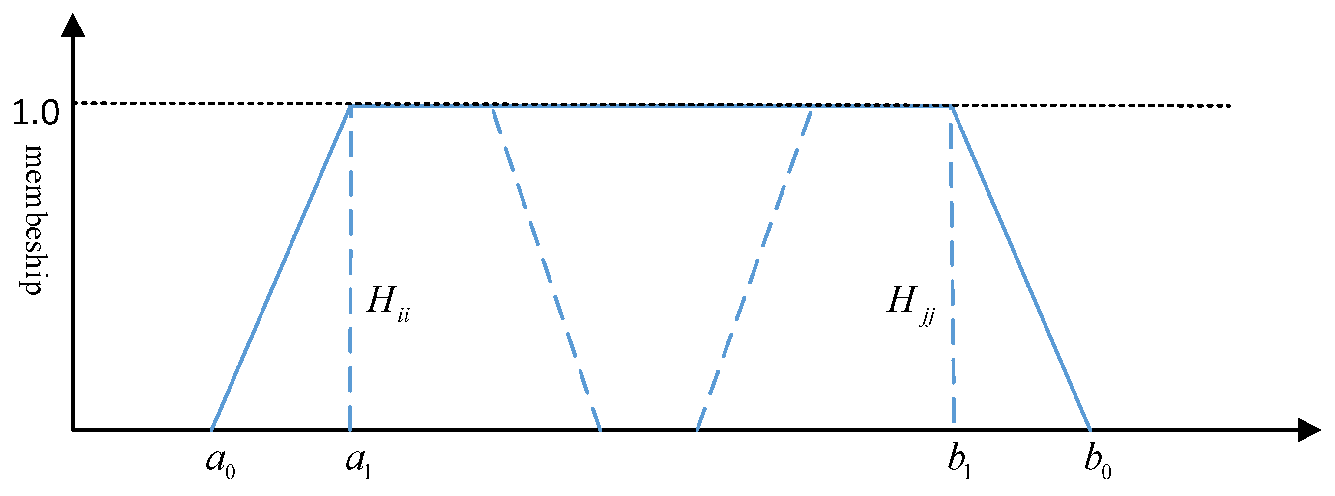
The defuzzification is focused on the transmission of a comprehensive fuzzy confidential structure to the explicit confidential structure. For this purpose, the fuzzy linguistic variables is first transferred to the explicit variables, and the methodology proposed by Chen and Klein [71] is applied in this study to transfer a trapezoidal fuzzy number of into an explicit value, which can be obtained by
where is the explicit value of the fuzzy linguistic expression . As with the trapezoidal fuzzy number used in this study, and are valued as 0 and 10, respectively. and are the marginal values when the membership function of is valued as 0, while and are the marginal values when the membership function of is valued as 1. The membership function is illustrated in Figure 5.
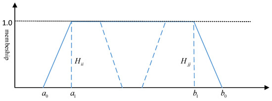
Figure 5.
Membership function for different evaluation expression.
To illustrate the calculation process, the fuzzy linguistic expression of is taken as an example. The trapezoidal fuzzy number for is (8,9,10,10) according to Table 1; then, , , and . As a result,
Similarly, all the can be transferred to their explicit values of , which are summarized as follows.
Next, the explicit comprehensive confidential structure can be obtained by
Finally, the explicit confidential matrix containing can be established in the form of
3.4. Application of TOPSIS to Rank Failure Modes
3.4.1. Explicit Confidential Matrix to Be Normalized and Weighted
To rank the identified failure modes based on the method introduced in Section 3.2.1 with consideration of O, S, and D using the TOPSIS method, the obtained explicit confidential matrix is first normalized by means of vector normalization [72], and the normalized explicit confidential matrix is represented by
where can be obtained according to by
Then, the normalized explicit confidential matrix is weighted with the consideration of the weights of O, S, and D, and the weighted matrix is expressed as
where is the weighted ,
where denotes the comprehensive weights of O, S, and D. The determination of in this study considers the integration of subjective and objective methods: the former is achieved by the expert elicitation, and the latter is presented by the entropy-weight method. The multiplicative synthesis method is employed in this study to integrate the results of subjective and objective calculation, which is calculated by
where is the weights obtained by the subjective method, and is the weights obtained from the objective calculation.
For the expert elicitation to obtain the subjective weights, the linguistic expressions and their corresponding fuzzy numbers are summarized in Table 2.
Table 2.
Linguistic expressions and their fuzzy numbers.
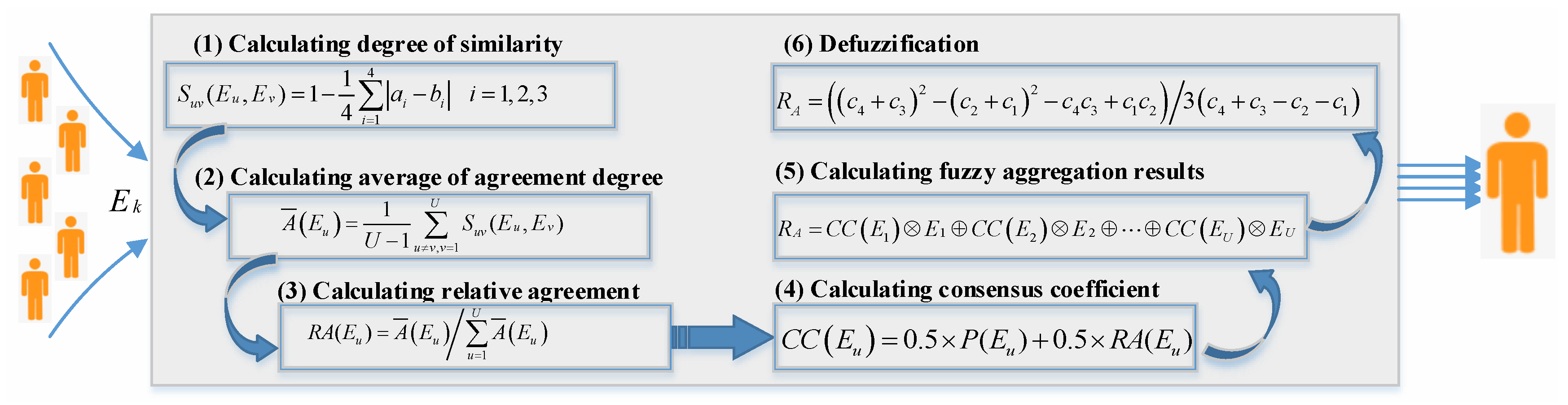
The experts’ judgments are collected and then processed by the fuzzy aggregation method [29]; the general principle is presented in Figure 6. The subjective weights by means of expert elicitation can be obtained as the normalized values of , which are obtained by

Figure 6.
Process of expert judgment aggregation.
The objective weights in Equation (20) are calculated by the entropy-weight method. Generally, the lower the information entropy determined by the data associated with the influencing factor, the greater the utility value of this information; thus, the weight of this influencing factor is greater. The information entropy of the O, S, and D can be defined as
where and can be determined by
Finally, the entropy-weight can be obtained by
3.4.2. Calculating Relative Closeness
According to the principle of TOPSIS [73], the positive ideal solution and negative ideal solution are presented as follows on the basis of the normalized and weighted explicit confidential matrix.
where and () are determined by
The distance between each failure mode and positive ideal solution/negative ideal solution can be calculated, respectively, by
Finally, the relative closeness of each failure mode can be obtained by
where is the relative closeness of the th failure mode. The higher value of relative closeness, the risk of the failure mode is higher, which should be paid much attention during safety management.
4. Application of the Proposed Methodology
4.1. Modeling the STS LNG Operational Process by STPA
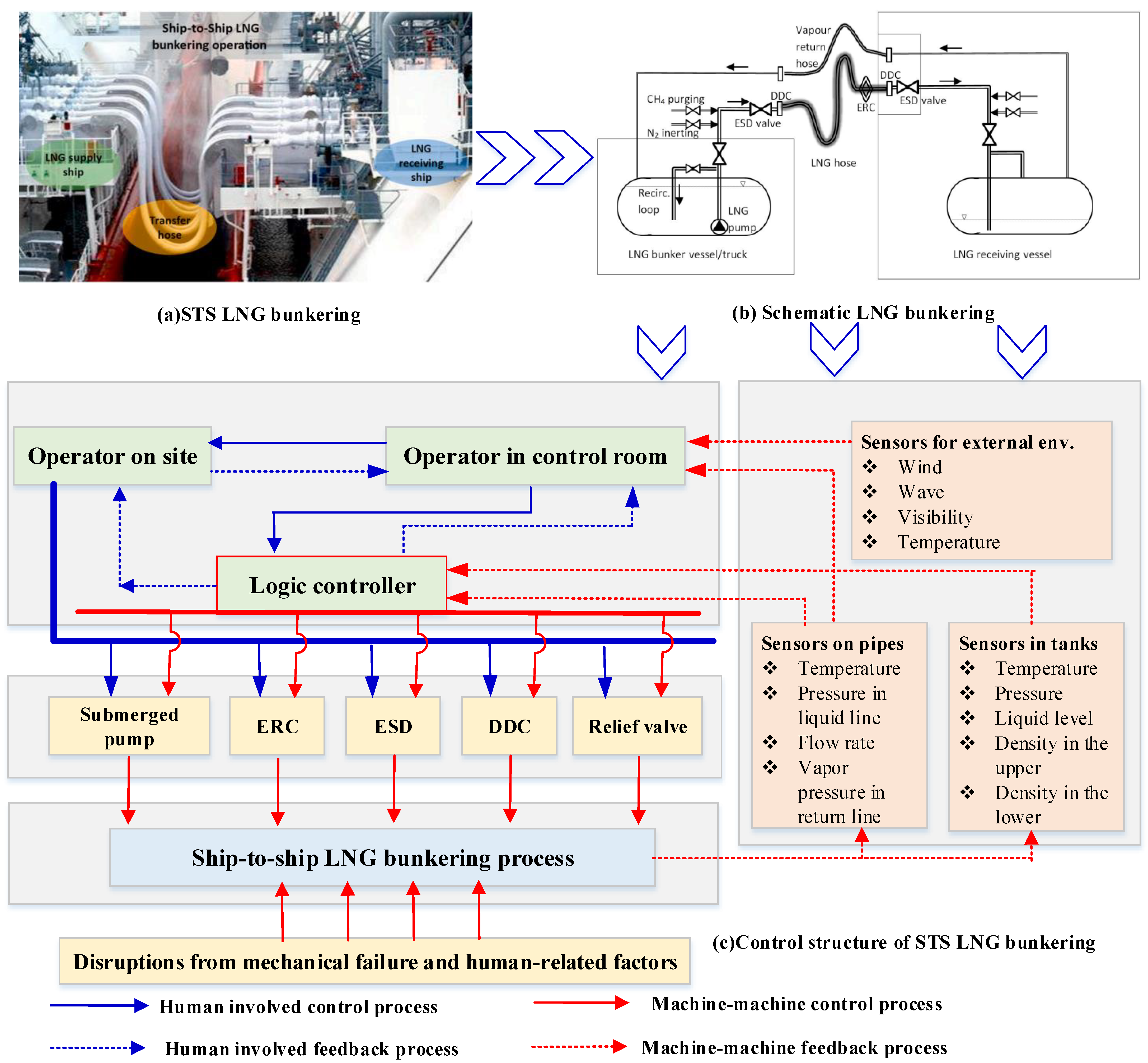
According to the report issued by Gullberg and Gahnstrom [17], the feasible technical solutions for STS LNG bunkering are characterized by flexible transfer hoses with different dimensions and numbers, and the simplified bunkering process is illustrated in Figure 6. It should be noted that some fittings on the pipelines are not included in this figure.
Figure 7b is the conceptual STS LNG bunkering process extracted from the industrial practice, which may be observed in Figure 7a. After all the preparation work, such as various inspections, purging the pipeline, and pre-cooling of the pipelines, the submerged pump in the LNG tanks of the bunker vessel starts to pump the LNG through the flexible hose to the LNG tanks on the receiving vessel. In addition to the main shut-off valves on the output of tank A and input of tank B, there are two emergency shut-down valves (ESDs) fitted close to the flexible hose connection flanges on both the vessels. The ESDs are actuated automatically or manually if leakage is detected, or any deviation from the normal operation. In addition, there is emergency release coupling (ERC) on the flexible hose, which is used to provide a “weak link” in the LNG pipeline. If the relative motions between the receiving vessel and bunker vessel exceed the limits of the flexible hose, then the ERC is actuated to disconnect the LNG pipeline and close both ends of the separated coupling. Practically, the dry disconnect couplings (DDCs) are arranged at the flexible hose connection flanges to prevent any spill from the hose when stowed away on the bunker vessel after bunkering. During the LNG bunkering process, the boil-off gas (BOG) from tank B on the receiving vessel is directed to tank A on the bunkering vessel through the vapor return hose, and ESDs, ERCs, and DDCs are also fitted on the vapor return hose as that of the LNG hose.
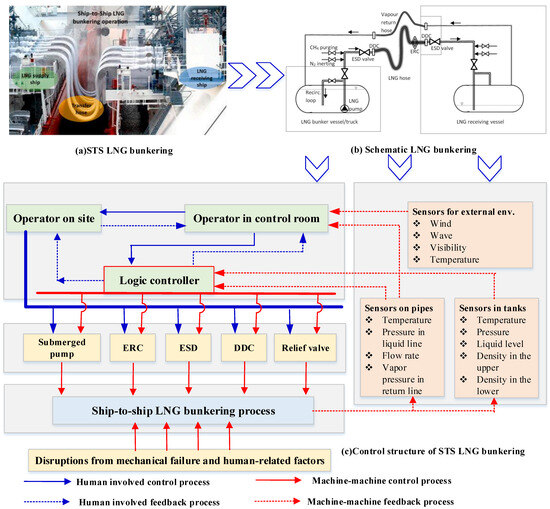
Figure 7.
General control structure of STPA extracted from the STS LNG bunkering process [17].
According to Figure 7b, before developing the control structure, potential accident types and various hazards at the system level should be determined. In this study, the potential accident types are defined as casualty event (A1), hull damage (A2), and bunkering system damage (A3) with reference to studies about STPA in the maritime industry [67,74], which are regarded as the consequences of various hazards. The identification of potential hazards at the system level in this study is mainly dependent on the literature review, including the relevant studies from Zhu et al. [74], Ahn et al. [75], Sultana et al. [68], and Gerbec and Aneziris [32]. In addition, some STS LNG bunkering guidelines issued by IAPH [18], the Swedish Marine Technology Forum (SMTF) [19], American Bureau of Shipping (ABS) [20], Korean Register of Shipping (KR) [21], and China Classification Society (CCS) [22] are also collected and analyzed in this study to facilitate the identification of various hazards involved in the STS LNG bunkering operation. As a result, the potential hazards are summarized in Table 3.
Table 3.
Hazards involved in the STS LNG bunkering operation.
The nine hazards identified at the system level are considered the failure mode from the perspective of FMEA. Then, the causes contributing to these hazards are further investigated with the help of unsafe control actions analysis in terms of the four aspects mentioned in Section 3.2.1, which is illustrated in Figure 3. For this purpose, the safety control structure corresponding to the STS LNG bunkering should be first established according to the basic principle of STPA, the results of which are illustrated in Figure 7c. Finally, all the failure modes and their consequences and causes are determined, which are summarized in Table 4.
Table 4.
Failure modes, causes, and consequences involved in STS LNG bunkering.
4.2. Fuzzy FMEA Analysis
4.2.1. Expert Weights and Elicitation
To evaluate these nine failure modes in terms of O, S, and D, according to the aforementioned selection criteria in Section 3.2.3, a heterogeneous group of experts was selected in this study to conduct the expert elicitation. The weights of these experts is evaluated according to their age, professional position, educational level, experience, as well as their certificate rank [29]. To ensure the professional and heterogeneity of the experts employed in this study, all the experts are characterized by experience of maritime shipping industry; meanwhile, these experts are from different sections, such as academic institutes, shipping companies, seafarers on LNG-Fueled ships, and port state control officers. Finally, five maritime professional experts are selected in this study, and their general information is summarized in Table 5.
Table 5.
General information of the experts employed in this study.
The capacity of these experts is then evaluated to value their weights. For this purpose, the methodology proposed in Section 3.2.3 is used in this study. To establish pairwise comparison matrices, a set of rating criteria is developed in terms of professional position, age, experience, education level, and certificate rank. Each indicator is scaled from 1 to 5: the higher the score, the more important the expert is. The score ratings are summarized in Table 6.
Table 6.
Rating criteria for the capacity evaluation.
To obtain the pairwise comparison matrices with the elements being fuzzy numbers, the difference in scores between two experts in terms of a specific evaluation indicator is represented by a fuzzy number, and the corresponding relationships between the difference in scores and fuzzy number are defined as in Table 7 with reference to Yazdi [70].
Table 7.
Relationships between difference in scores and fuzzy number.
Based on the contents presented in Table 4, Table 5 and Table 6, the pairwise comparison matrices for the expert capacity evaluation can be obtained in terms of age, education level, certificate rank, job experience, and professional position, which are denoted by , and , respectively.
Based on Equations (5)–(7), the synthetic pairwise comparison matrix can be determined as
The fuzzy weights of these five experts can be obtained according to Equation (8), the results of which are presented as
According to Equation (9), the fuzzy weight of each expert can be determined, the results of which are summarized as
Finally, the explicit weights for these experts can be determined by Equation (10), and the results are obtained as
These five maritime professional experts are then required to evaluate the identified failure modes in terms of their occurrence (O), severe (S), and detectability (D) in the form of safety meetings and questionnaires. The results are summarized in Table 8.
Table 8.
Results of expert elicitation for the failure modes evaluation.
4.2.2. Explicit Confidential Structure
The data contained in Table 8 are considered the input of Equation (14), and the results calculated from Equation (14) are used to develop an explicit confidential matrix, which is expressed as
in this study illustrates the calculation process of the elements in the explicit confidential matrix, and the calculation process is shown as
Then, the explicit confidential matrix is normalized with the application of Equation (17), the results of which are presented as
To weight the elements contained in the normalized confidential matrix , the weights of O, S, and D are valued with the application of Equations (18)–(24). Firstly, the subjective weights of O, S, and D are determined through the method described in Figure 3 on the basis of the expert elicitation, which are summarized in Table 9. The results are 0.3272, 0.3566, and 0.3162, respectively.
Table 9.
Expert elicitation results to determine weights of O, S, and D.
Then, the objective weights of O, S, and D can be determined on the basis of the normalized confidential matrix with the application of Equations (22)–(25); as a result, the objective weights of O, S, and D are valued as 0.4608, 0.3505, and 0.1877, respectively. Therefore, based on the abovementioned subjective weights and objective weights of O, S, and D, the comprehensive weights of O, S, and D can be calculated by Equation (20), the results of which are presented in Table 10.
Table 10.
Weights of O, S, and D.
As a result, the normalized explicit confidential matrix can be weighted, with the weights presented in Table 9, by Equation (19), the results of which are expressed as
4.3. Risk Assessment by TOPSIS
Both the positive ideal and negative ideal solutions of the issue solved in this study can be obtained through the weighted and normalized explicit confidential matrix according to Equation (25), the results of which are presented as follows.
Then, the distance between each failure mode and the positive/negative ideal solution can be calculated with the application of Equation (28a,b), and the results are summarized in Table 11. In addition, the results of relative closeness are also summarized in Table 11.
Table 11.
Distance to positive/negative ideal solution and relative closeness of each failure mode.
According to the principle of FMEA-TOPSIS in this study, the relative closeness of the failure mode can be used to describe the risk level of each failure mode: the higher the relative closeness, the higher the risk level of the failure mode. It can be observed that the deviation between the highest and lowest relative closeness values of the failure modes summarized in Table 11 is 0.0347, which indicates that the risk levels of all the identified failure modes in this study should be paid considerable attention to. Furthermore, if all the relative closeness values are regarded as a series of numbers, then the variance of the relative closeness values can be obtained as
where is the average of relative closeness, and is the total number of failure modes in this study. Meanwhile, the standard deviation is valued as 0.0107 according to the variance. The results of variance and standard deviation imply that STS LNG bunkering operation should be implemented carefully because there are no prominent risks among all the identified risks.
5. Findings and Extended Discussions
According to the results presented in Table 11, H4 (high-high pressure in vapor return line) should be prioritized in terms of risk management during STS LNG bunkering. High pressure in vapor return line is also regarded as an important indicator to pause the bunkering operation [75]. The size of the vapor return line is much smaller than that of the LNG hose [16], and the temperature is higher due to natural gas flowing within. Actually, the prevention of high pressure in the vapor return line is the critical content for boil-off gas (BOG) management, which is an obvious challenge of STS LNG bunkering operation [47,50]. The high risks involved in high pressure in the vapor return line mainly lie in the complexity of its causes, which may cover many factors, such as pressure of the receiving tank, temperature difference between bunker tank and receiving tank, bunkering flow rate, and insulation of the return line. According to the study conducted by Lee et al. [47], the pressure of the receiving tank is the most important factor influencing pressure in the vapor return line, and the flow rate of LNG is also an important contributing factor. Therefore, it is advised to reasonably determine the bunkering flow rate considering the bunkering operation time and return vapor flow rate, which are limited mainly by the heat ingress and pressure fluctuation. Practically, at the beginning of the bunkering operation, the pressure in the vapor return line should be paid much attention because overpressure in the vapor return line is likely to occur under conditions of insufficient pre-cooling or heat ingress. In addition, it is interesting to find H9 (high flow rate of LNG in pipelines) is ranked as the second most important risk signal following H4. Under normal operational conditions, the flow rate of bunkering LNG is well controlled by the logic controller, control valve, and the frequency converter based on the feedback signals from flow rate sensors. The reasons for the high flow rate of bunkering LNG are complex, and the most obvious reason is the mechanical failure of the control valve and flow rate sensors. Actually, the high flow rate of bunkering LNG can also be caused by the malfunctioning of the ERS after the occurrence of bunkering LNG leakage, such as the ERS failing to be actuated or actuated too late in case of bunkering LNG leakage. Therefore, it is necessary to pay close attention to the flow rate of the bunkering LNG during the STS LNG bunkering operation.
LNG leakage in the flexible hose (H2) is ranked as the third most important risk signal according to the results presented in Table 11. The main reason may lie in the fact that LNG leakage is paid the most attention by the operator during STS LNG bunkering. Leaky LNG may lead to fire in case of ignition, and under normal operational conditions, the ESD system may actuated by the LNG leakage. In the field of practical engineering, LNG leakage occurs during bunkering operations; particularly, leakage occurring in the flexible hose or the hose arm has attracted much attention, and a lot of available data about hose failure have been reported or published according to the review study made by Gerbec and Aneziris [32], such as DNV GL [76]. LNG leakage in the hose may occur at the location of coupling and connecting flanges, or other joints. The external or internal causes contributing to the LNG hose leakage are not well investigated due to the lack of a practical dataset; they may be attributed to hose quality issues, fatigue damage, low temperature damage, and human-related error [56]. The general operational reliability of the operators on-site during STS LNG bunkering is assessed in the study conducted by Ahn et al. [75] and Uflaz et al. [27]. Generally, the probability of hose leakage is determined by many factors, such as the failure rate of joints (couplings, and connecting flanges), and the fatigue of the bunkering hose (duration and number of bunkering operations). Even though there are rarely reports that LNG hose leakage is directly caused by the inappropriate operation of the crew on-site, the control and management of hose quality issues and fatigue damage are greatly dependent on the responsible operation of the crew on-site, such as careful inspection before bunkering operations, and the proper maintenance of LNG hose.
Even though the failure modes investigated in this study are mainly focused on the LNG bunkering operation process, the causes or prevention measures may stem from the preparation and after bunkering activities. Therefore, it is necessary to overview all the operational procedures of the STS LNG bunkering operation, which have been addressed by an advisory committee on LNG-fueled ships of the IAPH. For this purpose, the abovementioned operational procedures are clarified in this study with reference to Uflaz et al. [27] and IAPH [18], during which hierarchical task analysis (HTA) is applied to decompose the whole operation process, and the results can be found in the Appendix A. As a result, the prevention and management of the failure modes in this study may be beneficial by means of paying much attention to some sub-tasks listed in Table A1 in Appendix A, which are summarized in Table 12.
Table 12.
Sub-tasks in STS LNG bunkering operation contributing to failure mode prevention.
Based on the contents presented in Table 12, it can clearly be observed that each failure mode identified in this study can be prevented or controlled by a group of sub-tasks, which causes a change by means of AND or OR gate. In addition, according to Table 12, 77.14% of the total sub-tasks are attributed to pre-bunkering activities, which indicates the criticality of the various inspections before bunkering operations, and interestingly, there are three failure modes, namely, F1, F2, and F5, all of which can be effectively prevented or controlled by measures before bunkering operations according to Table 12. Anyway, all the failure modes can be prevented or controlled by means of taking measures recommended in the STS LNG bunkering checklist. It should be kept in mind that the specific checklists for bunkering scenarios may differ due to different safety constraints or requirements. Therefore, in practical engineering, a specific STS LNG bunkering checklist is prepared with accordance to LNG bunkering guidelines, which may include but is not limited to IAPH [18], Swedish Marine Technology Forum [19], American Bureau of Shipping [20], Korean Register of Shipping [21], and China Classification Society [22].
6. Conclusions
The hazardous events involved in STS LNG bunkering operations are quantitatively assessed by a comprehensive methodology integrating fuzzy FMEA and TOPSIS proposed in this study. In detail, the STS LNG bunkering process is first decomposed according to the principle of STPA to identify potential failure modes and their causes and consequences; then, the occurrence, severity, and detectability of these failure modes are assessed by a group of heterogeneous experts with application of fuzzy confidential structure analysis. Consequently, the developed fuzzy confidential matrix is transferred into the explicit confidential matrix, which is regarded as the input of TOPSIS to rank the risk level of these failure modes. The findings and managerial implications of this study are summarized as follows.
- (1)
- There are a total of nine failure modes identified in this study during the STS LNG bunkering operation process, and the results show that “high-high pressure in vapor return line” (F4) is valued as the highest risk level, while “High flow rate of LNG in pipelines” (F9) and “LNG leakage in the flexible hose” (F2) are ranked as the second and the third highest risk level, respectively.
- (2)
- The safety checklist developed by IAPH [18] is used in this study to match the identified failure modes, and the results show that all these failure modes can be well prevented or controlled by the preventive measures listed in the safety checklist. It is interesting to find that 77.14% of these selected preventive measures are attributed to pre-bunkering activities. Furthermore, both the “Detection of natural gas in cargo machinery space” (F1) and “Power failure for emergency valves” (F9) can be well prevented by means of conducting pre-bunkering activities. This finding verifies the criticality of implementing a safety checklist.
- (3)
- In this study, both the “high-high pressure in vapor line” and “LNG leakage in the flexible hose” are valued by high risk level, which indicates the importance of BOG management and leakage management during the STS LNG bunkering. Even though LNG leakage and BOG management have been paid much attention to in different versions of operational guidelines, they can be further emphasized by means of developing specific operational manuals. Meanwhile, emergency plans can be further detailed by implementing simulation.
- (4)
- It is necessary to prepare a specific tailored safety checklist for an individual STS LNG bunkering operation with a concentration on the potential failure modes identified in this study. It should be noted that there are different versions of STS LNG bunkering operation guidelines; the suitable one should be selected according to the operational scenarios. The identified inspection items listed in Table 11 may be helpful for the preparation and monitoring of the bunkering operation on-site.
Even though the results of the present study can be potentially applied to improve the safety of STS LNG bunkering operations, there are still aspects that can be further improved. Since this study is based on expert evaluations, it may be subject to bias, and the lack of real-world LNG bunkering failure data could impact the generalizability of the findings. Ideally, the failure modes involved in the bunkering process should be identified by means of failure data analysis or text mining. However, there are limited data about the failure of bunkering operations. In addition, the results are obtained on the basis of a group of experts whose knowledge may be limited, which may lead to slight deviation from a specific engineering scenario. To address these two issues, in the near future, the methodology proposed in this study should be integrated in the form of pseudo-code, which can be further processed to develop an applet being suitable to a specific operational scenario and a specific group of experts. In addition, to improve the accuracy of this methodology, failure data about LNG bunkering should be accumulated by means of practical collection and simulation.
Author Contributions
Conceptualization, X.M.; Methodology, W.F., S.D. and W.Q.; Formal analysis, W.F., Z.W. and X.D.; Investigation, Z.W. and W.Q.; Resources, X.M.; Data curation, S.D.; Writing—original draft, W.F. and X.D.; Writing—review & editing, W.Q. All authors have read and agreed to the published version of the manuscript.
Funding
This study was funded by China postdoctoral science foundation (Grant No. 2022M720626), Humanities and Social Sciences Program of the Ministry of Education (Grant No. 23YJCZH171), Project of “Risk assessment and emergency response system verification during LNG powered vessel berthing (Grant No. Z2412-096)”, and the Fundamental Research Funds for the Central Universities (3132023530).
Data Availability Statement
The original contributions presented in this study are included in the article. Further inquiries can be directed to the corresponding author.
Conflicts of Interest
Author Shengli Dong was employed by the company Shanghai Ship and Shipping Research Institute Co., Ltd. The remaining authors declare that the research was conducted in the absence of any commercial or financial relationships that could be construed as a potential conflict of interest.
Appendix A
Table A1.
Checklist of STS LNG bunkering operation (pre-bunkering, during bunkering, and after bunkering).
Table A1.
Checklist of STS LNG bunkering operation (pre-bunkering, during bunkering, and after bunkering).
| 1. Pre-bunkering | |
| 1.1. | According to the local regulations, the competent authorities and bunker ship are notified of the start of bunkering operations |
| 1.2. | Both the ships should confirm the weather and sea condition, as well as the limitations for aborting the operation |
| 1.3. | Ensure a secure mooring connection between your vessel and the LNG bunker vessel in compliance with regulatory requirements, considering proper mooring arrangements, adequate tensioning, and safe rendering |
| 1.4. | Ensure the provision of a safe and secure means of access between your vessel and the LNG bunker vessel |
| 1.5. | Ensure all required firefighting equipment is prepared for immediate use, and coordinate smoking regulations along with other fire prevention measures |
| 1.6. | Ensure the bunkering operation area is adequately illuminated |
| 1.7. | Verify that both your vessel and the LNG bunker vessel can maneuver safely under their own power without obstructions |
| 1.8. | Ensure responsible officers on both your vessel and the LNG bunker vessel provide adequate supervision throughout the bunkering operation |
| 1.9. | Establish, test, and confirm an effective primary and emergency communication system between the responsible operators and supervisors on both your vessel and the LNG bunker vessel. Ensure agreement on the communication language |
| 1.10. | Agree upon, test, and clearly explain the emergency stop signal and shut-down procedures to all relevant personnel |
| 1.11. | Ensure that those in charge are familiar with emergency procedures, response plans, and contact numbers |
| 1.12. | Establish a predefined restricted area, clearly marked with appropriate sign-age. Ensure the area is free from other vessels, unauthorized personnel, objects, and potential ignition sources |
| 1.13. | Establish and agree on safety procedures and mitigation measures to prevent falling objects, ensuring all parties involved adhere to them |
| 1.14. | Maintain an active deck watch on the ship. Maintain an effective LNG bunker watch, both on board and on board the LNG bunker |
| 1.15. | Close all external doors, portholes, and accommodation ventilation inlets in accordance with the operating manual |
| 1.16. | Conduct an operational test of the gas detection equipment to ensure it is functioning properly and in good working condition |
| 1.17. | Material Safety Data Sheets (MSDS) for delivered LNG fuel must be on board |
| 1.18. | Enforce regulations regarding ignition sources |
| 1.19. | Ensure that suitable and sufficient protective clothing and equipment are readily available. Personnel involved in connecting and disconnecting bunker hoses, as well as those in the immediate vicinity, must wear appropriate protective gear |
| 1.20. | Install a [powered] emergency release coupling (ERC) and ensure it is ready for immediate activation |
| 1.21. | Conduct a functional test of the water spray system and ensure it is prepared for immediate deployment |
| 1.22. | Verify that Spill containment arrangements are properly set up, equipped with suitable materials, have adequate capacity, and are empty |
| 1.23. | Verify that hull and deck protection against low temperature is present |
| 1.24. | Verify that bunker pumps and compressors are in good working order |
| 1.25. | Verify that all control valves are in good condition and in good working order |
| 1.26. | Ensure that the bunker system gauges, high-level alarms, and high-pressure alarms are operational, properly calibrated, and in good working condition |
| 1.27. | Ensure the ship’s bunker tanks are safeguarded against accidental overflow, continuously monitor tank contents, and verify that alarms are correctly set |
| 1.28. | Inspect, test, and confirm that all safety and control devices in the LNG installations are fully operational and in good working condition |
| 1.29. | Ensure that pressure control equipment, as well as boil-off and re-liquefaction systems, are functioning properly and in good working condition |
| 1.30. | Properly connect and securely support the vapor connections |
| 1.31. | Confirm that Emergency Shutdown Systems (ESDs), automatic valves, or equivalent devices have been tested, are fully operational, and ready for use on both your vessel and the LNG bunker vessel. Ensure agreement on the closing rates of the ESDs |
| 1.32. | Inspect the initial LNG bunker line up. Close unused connections, blank and bolt completely |
| 1.33. | Verify that LNG bunker hoses, fixed pipelines, and manifolds are in good condition, correctly equipped and supported, properly connected, leak-tested, and certified for LNG transfer |
| 1.34. | Establish the LNG bunker connection between the vessel and the LNG bunker ship using dry disconnection couplings |
| 1.35. | Ensure the LNG bunker connection between the own ship and the LNG bunker ship is equipped with sufficient electrical isolation measures |
| 1.36. | Ensure that dry breakaway couplings are installed on LNG bunker connections, and visually inspect them to confirm they are functioning properly and in good working condition |
| 1.37. | Locate the ship’s emergency fire control plans externally |
| 1.38. | Provide an International Shore Connection |
| 1.39. | Conduct an information exchange regarding pre-cooling, inerting, cooling down, vapor management, transfer rates during the initial, bulk, topping stages, and the filling sequence |
| 1.40. | Perform the initial pre-cooling of the LNG transfer systems on both vessels that can be completed either with the use of nitrogen or with LNG. Aware of the risks of cryogenic hazards, introducing oxygen in confined spaces, and boil-off-gas (if inerting with LNG) during this activity |
| 1.41. | Inform coastal maritime authorities of the starting of bunkering operations, as well as the other vessels in the vicinity |
| 2. During bunkering activities | |
| 2.1. | Confirm and agree on the starting temperatures, pressures, as well as the available tank capacity before commencing operations |
| 2.2. | Establish an agreement on the transfer quantity, initial manifold pressure, starting transfer rate, maximum transfer rate, topping-up rate, and maximum allowable manifold pressure |
| 2.3. | Agree on the maximum and minimum limits for bunkering pressures, LNG bunker tank pressures, LNG temperatures, and the filling limit of the LNG bunker tanks |
| 2.4. | Commence operations at the agreed transfer rates, ensuring compliance with the specified temperatures, pressures, and tank capacity |
| 2.5. | Continuously monitor the bunker transfer quantities, temperatures, pressures, and tank capacity throughout the operation |
| 2.6. | Handle vented and boil-off gas in accordance with the agreed-upon plan |
| 2.7. | Continuously monitor weather conditions and remain alert for any unexpected deterioration |
| 2.8. | Make necessary adjustments to mooring lines, bunker hoses, and arms |
| 2.9. | Periodically test the communication equipment and methods |
| 3. After bunkering activities | |
| 3.1. | Purge the LNG bunker hoses, stationary pipelines, and manifolds, ensuring they are properly prepared and maintained for disconnection |
| 3.2. | Close both remote and manually operated valves, ensuring they are properly prepared and maintained for disconnection |
| 3.3. | Inspect all pressure relief valves and vents to ensure they are functioning properly and to prevent the risk of overpressurization |
| 3.4. | Inert the bunker transfer pipeline and hose using nitrogen before proceeding with the disconnection |
| 3.5. | Deactivate the restricted area following the disconnection procedure |
| 3.6. | Notify competent authorities and terminal that LNG bunker operations have been completed and other vessels in the vicinity have been notified as required |
| 3.7. | Report near misses and incidents to competent authorities if applicable |
References
- Peng, P.; Lu, F.; Cheng, S.; Yang, Y. Mapping the global liquefied natural gas trade network: A perspective of maritime transportation. J. Clean. Prod. 2021, 283, 124640. [Google Scholar]
- Aguilera, R.F. The role of natural gas in a low carbon Asia Pacific. Appl. Energy 2014, 113, 1795–1800. [Google Scholar]
- UNCTAD. Review of Maritime Transport. 2023. Available online: https://unctad.org/publication/review-maritime-transport-2023 (accessed on 31 May 2024).
- Clarksons Research. Timeseries and Graphs. Orderbook by Ship Type, All Vessels. 2023. Available online: https://www.clarksons.net (accessed on 31 May 2024).
- IMO. Initial IMO Strategy on Reduction of GHG Emissions from Ships, Resolution MEPC; International Maritime Organization: London, UK, 2018; Volume 304. [Google Scholar]
- Li, C.; Wang, Z.; Liu, H.; Guo, F.; Li, C.; Xiu, X.; Wei, L. Exergetic and exergoeconomic evaluation of an SOFC-Engine-ORC hybrid power generation system with methanol for ship application. Fuel 2024, 357, 129944. [Google Scholar]
- Yeo, S.; Jeong, B.; Lee, W.J. Improved formal safety assessment methodology using fuzzy TOPSIS for LPG-fueled marine engine system. Ocean Eng. 2023, 269, 113536. [Google Scholar]
- Kistner, L.; Bensmann, A.; Hanke-Rauschenbach, R. Potentials and limitations of battery-electric container ship propulsion systems. Energy Convers. Manag. 2024, 21, 100507. [Google Scholar]
- Nubli, H.; Jung, D.; Kim, S.J.; Sohn, J.M. Structural impact under accidental LNG release on the LNG bunkering ship: Implementation of advanced cryogenic risk analysis. Process Saf. Environ. 2024, 186, 329–347. [Google Scholar]
- EMSA. Guidance on LNG Bunkering to Port Authorities and Administrations; European Maritime Safety Agency: Lisboa, Portugal, 2018; Available online: https://www.emsa.europa.eu/publications/item/3207-guidance-on-lng-bunkering-to-port-authorities-and-administrations.html (accessed on 13 February 2023).
- Zhu, M.; Huang, L.; Huang, Z.; Shi, F.; Xie, C. Hazard analysis by leakage and diffusion in Liquefied Natural Gas ships during emergency transfer operations on coastal waters. Ocean Coast. Manag. 2022, 220, 106100. [Google Scholar]
- Nikhalat-Jahromi, H.; Angeloudis, P.; Bell, M.G.H.; Cochrane, R.A. Global LNG trade: A comprehensive up to date analysis. Marit. Econ. Logist. 2017, 19, 160–181. [Google Scholar]
- Vanem, E.; Antao, P.; Østvik, I.; de Comas, F.D.C. Analysing the risk of LNG carrier operations. Reliab. Eng. Syst. Saf. 2007, 93, 1328–1344. [Google Scholar]
- Zhao, W.; McPhail, F. Roll response of an LNG carrier considering the liquid cargo flow. Ocean Eng. 2017, 129, 83–91. [Google Scholar]
- European Commission. eMARS: Electronic Major Accident Report System [WWW Document]. 2021. Available online: https://emars.jrc.ec.europa.eu/en/emars/content (accessed on 12 May 2023).
- Arnet, N.M.L. LNG Bunkering Operations: Establish Probabilistic Safety Distances for LNG Bunkering Operations. Master’s Thesis, Institutt for Energi-og Prosessteknikk, Trondheim, Norway, 2014. [Google Scholar]
- Gullberg, M.; Gahnström, J. North European LNG Infrastructure Project—A Feasibility Study for an LNG Filling Station Infrastructure and Test of Recommendations. Danish Maritime Authority, In Report Danish Maritime Authority Mogens Schrøder Bech Baseline Report ÅF Industry AB SSPA Sweden AB 181. 2012. Available online: https://www.dma.dk/ (accessed on 1 March 2024).
- IAPH. LNG Bunker Checklist Ship to Ship Including Terminal Information Sheet. 2019. Available online: https://sustainableworldports.org/wp-content/uploads/IAPH-Liquefied-Gas-Bunker-Checklist-STS-A-v4.0.pdf. (accessed on 20 May 2024).
- Swedish Marine Technology Forum. LNG Ship to Ship Bunkering Procedure. 2022. Available online: https://safety4sea.com/lng-ship-to-ship-bunkering-procedure (accessed on 13 March 2024).
- ABS. Guide for LNG Bunkering; American Bureau of Shipping: Houston, TX, USA, 2017. [Google Scholar]
- KR. Guidelines for Safe STS LNG Transfer Operation; Korean Register of Shipping: Busan, Republic of Korea, 2023; Available online: https://www.imarine.cn/wp-content/uploads/2023/12/%E9%BE%99de%E8%88%B9%E4%BA%BAGuidelines-for-Safe-STS-LNG-Transfer-Operation1.pdf (accessed on 13 April 2024).
- CCS. Guidelines for STS Transfer Operation Plan; China Classification Society: Beijing, China, 2021. (In Chinese) [Google Scholar]
- Vairo, T.; Gualeni, P.; Reverberi, A.P.; Fabiano, B. Resilience Dynamic Assessment Based on Precursor Events: Application to Ship LNG Bunkering Operations. Sustainability 2021, 13, 6836. [Google Scholar] [CrossRef]
- Fan, H.; Enshaei, H.; Jayasinghe, S.G. Dynamic quantitative risk assessment of LNG bunkering SIMOPs based on Bayesian network. J. Ocean Eng. Sci. 2023, 8, 508–526. [Google Scholar] [CrossRef]
- Wu, J.; Bai, Y.; Zhao, H.; Hu, X.; Cozzani, V. A quantitative LNG risk assessment model based on integrated Bayesian-Catastrophe-EPE method. Saf. Sci. 2021, 137, 105184. [Google Scholar] [CrossRef]
- Fan, H.; Enshaei, H.; Jayasinghe, S.G. Safety philosophy and risk analysis methodology for LNG bunkering simultaneous operations (SIMOPs): A literature review. Saf. Sci. 2021, 136, 105150. [Google Scholar] [CrossRef]
- Uflaz, E.; Sezer, S.I.; Akyuz, E.; Arslan, O.; Kurt, R.E. A human reliability analysis for ship to ship LNG bunkering process under DS evidence fusion HEART approach. J. Loss Prev. Process Ind. 2022, 80, 104887. [Google Scholar] [CrossRef]
- Vairo, T.; Pettinato, M.; Reverberi, A.P.; Milazzo, M.F.; Fabiano, B. An approach towards the implementation of a reliable resilience model based on machine learning. Process Saf. Environ. 2023, 172, 632–641. [Google Scholar]
- Qiao, W.; Liu, Y.; Ma, X.; Liu, Y. Human factors analysis for maritime accidents based on a dynamic fuzzy Bayesian network. Risk Anal. 2020, 40, 957–980. [Google Scholar] [CrossRef]
- Stokes, J.; Moon, G.; Bend, R.; Owen, D.; Wingate, K.; Waryas, E. Understanding the human element in LNG bunkering. In Marine Technology and Standards; American Society of Mechanical Engineers: New York, NY, USA, 2023; Volume 99403, pp. 105–111. [Google Scholar]
- Fan, H.; Enshaei, H.; Jayasinghe, S.G. Human error probability assessment for LNG bunkering based on fuzzy Bayesian network-CREAM model. J. Mar. Sci. Eng. 2022, 10, 333. [Google Scholar] [CrossRef]
- Gerbec, M.; Aneziris, O. Uncertainties in failure rates in the LNG bunkering risk assessment. Saf. Sci. 2022, 152, 105774. [Google Scholar]
- Nubli, H.; Sohn, J.M.; Jung, D. Consequence analysis of accidental LNG release on the collided structure of 500 cbm LNG bunkering ship. J. Mar. Sci. Eng. 2022, 10, 1378. [Google Scholar] [CrossRef]
- Zhang, W.; Yu, Y.; Wu, B.; Wan, C.; Yu, N.; Song, Y. A Fuzzy Bayesian Network–Based Method for Evaluating the Leakage Risk of STS LNG Bunkering. ASME J. Risk Uncertain. Part A 2024, 10, 04023066. [Google Scholar] [CrossRef]
- Lim, B.H.; Ng, E.Y.K. Model for cryogenic flashing LNG leak. Appl. Sci. 2021, 11, 9312. [Google Scholar] [CrossRef]
- Nguyen, V.T.; Raghavan, V.S.; Quek, R.Y.; How, L.B.; Yan, D. Reduced order models for uncertainty quantification of gas plumes from leakages during LNG bunkering. J. Loss Prev. Process Ind. 2022, 76, 104724. [Google Scholar]
- Duong, P.A.; Ryu, B.R.; Jung, J.; Kang, H. A Comprehensive Review of the Establishment of Safety Zones and Quantitative Risk Analysis during Ship-to-Ship LNG Bunkering. Energies 2024, 17, 512. [Google Scholar] [CrossRef]
- Carboni, M.; Pio, G.; Mocellin, P.; Vianello, C.; Maschio, G.; Salzano, E. Accidental release in the bunkering of LNG: Phenomenological aspects and safety zone. Ocean Eng. 2022, 252, 111163. [Google Scholar]
- Jeong, B.; Lee, B.S.; Zhou, P.; Ha, S.M. Determination of safety exclusion zone for LNG bunkering at fuel-supplying point. Ocean Eng. 2018, 152, 113–129. [Google Scholar]
- Park, S.; Jeong, B.; Yoon, J.Y.; Paik, J.K. A study on factors affecting the safety zone in ship-to-ship LNG bunkering. Ships Offshore Struct. 2018, 13, 312–321. [Google Scholar]
- Park, S.I.; Paik, J.K. A hybrid method for the safety zone design in truck-to-ship LNG bunkering. Ocean Eng. 2022, 243, 110200. [Google Scholar]
- Park, S.I.; Kim, S.K.; FREng, J.K.P. Safety-zone layout design for a floating LNG-Fueled power plant in bunkering process. Ocean Eng. 2020, 196, 106774. [Google Scholar]
- Jeong, B.; Park, S.; Ha, S.; Lee, J.U. Safety evaluation on LNG bunkering: To enhance practical establishment of safety zone. Ocean Eng. 2020, 216, 107804. [Google Scholar]
- Duong, P.A.; Ryu, B.R.; Jung, J.; Kang, H. Comparative analysis on vapor cloud dispersion between LNG/liquid NH3 leakage on the ship to ship bunkering for establishing safety zones. J. Loss Prev. Process Ind. 2023, 85, 105167. [Google Scholar] [CrossRef]
- Dobrota, Đ.; Lalić, B.; Komar, I. Problem of boil-off in LNG supply chain. Trans. Marit. Sci. 2013, 2, 91–100. [Google Scholar] [CrossRef]
- Benito, A. Accurate Determination of LNG Quality Unloaded in Receiving Terminals: An Innovative Approach; GERG Academic Network Event: Brussels, Belgium, 2009. [Google Scholar]
- Lee, H.; Choi, J.; Jung, I.; Lee, S.; Yoon, S.; Ryu, B.; Kang, H. Effect of parameters on vapor generation in ship-to-ship liquefied natural gas bunkering. Appl. Sci. 2020, 10, 6861. [Google Scholar] [CrossRef]
- Shao, Y.; Lee, Y.H.; Kim, Y.T.; Kang, H.K. Parametric investigation of BOG generation for ship-to-ship LNG bunkering. J. Korean Soc. Mar. Environ. Saf. 2018, 24, 352–359. [Google Scholar] [CrossRef]
- Shao, Y.; Lee, Y.; Kang, H. Dynamic optimization of boil-off gas generation for different time limits in liquid natural gas bunkering. Energies 2019, 12, 1130. [Google Scholar] [CrossRef]
- Kim, K.; Park, K.; Roh, G.; Chun, K. Case study on boil-off gas (BOG) minimization for LNG bunkering vessel using energy storage system (ESS). J. Mar. Sci. Eng. 2019, 7, 130. [Google Scholar] [CrossRef]
- Kutlu, A.C.; Ekmekçioğlu, M. Fuzzy failure modes and effects analysis by using fuzzy TOPSIS-based fuzzy AHP. Expert Syst. Appl. 2012, 39, 61–67. [Google Scholar] [CrossRef]
- Park, C.; Kontovas, C.; Yang, Z.; Chang, C.H. A BN driven FMEA approach to assess maritime cybersecurity risks. Ocean Coast. Manag. 2023, 235, 106480. [Google Scholar] [CrossRef]
- Wan, C.; Yan, X.; Zhang, D.; Qu, Z.; Yang, Z. An advanced fuzzy Bayesian-based FMEA approach for assessing maritime supply chain risks. Transp. Res. E-Log. 2019, 125, 222–240. [Google Scholar] [CrossRef]
- Liu, P.; Wu, Y.; Li, Y.; Wu, X. An improved FMEA method based on the expert trust network for maritime transportation risk management. Expert Syst. Appl. 2024, 238, 121705. [Google Scholar] [CrossRef]
- Liu, P.; Shen, M.; Geng, Y. Risk assessment based on failure mode and effects analysis (FMEA) and WASPAS methods under probabilistic double hierarchy linguistic term sets. Comput. Ind. Eng. 2023, 186, 109758. [Google Scholar]
- Kang, Z.; Li, Z.; Kang, J. Risk management framework of LNG offshore transfer and delivery system. Ocean Eng. 2022, 266, 113043. [Google Scholar]
- Goksu, S.; Arslan, O. A quantitative dynamic risk assessment for ship operation using the fuzzy FMEA: The case of ship berthing/unberthing operation. Ocean Eng. 2023, 287, 115548. [Google Scholar]
- Ceylan, B.O.; Akyar, D.A.; Celik, M.S. A novel FMEA approach for risk assessment of air pollution from ships. Mar. Policy 2023, 150, 105536. [Google Scholar]
- Ceylan, B.O. Shipboard compressor system risk analysis by using rule-based fuzzy FMEA for preventing major marine accidents. Ocean Eng. 2023, 272, 113888. [Google Scholar] [CrossRef]
- Akyuz, E.; Celik, E. A quantitative risk analysis by using interval type-2 fuzzy FMEA approach: The case of oil spill. Marit. Policy Manag. 2018, 45, 979–994. [Google Scholar] [CrossRef]
- Akyuz, E. Application of fuzzy FMEA to perform an extensive risk analysis in maritime transportation engineering. Int. J. Marit. Eng. 2018, 159, 99–105. [Google Scholar]
- Iranitalab, A.; Khattak, A. Comparison of four statistical and machine learning methods for crash severity prediction. Accid. Anal. Prev. 2017, 108, 27–36. [Google Scholar]
- Pei, Z. A note on the TOPSIS method in MADM problems with linguistic evaluations. Appl. Soft Comput. 2015, 36, 24–35. [Google Scholar]
- Asuquo, M.P.; Wang, J.; Zhang, L.; Phylip-Jones, G. Application of a multiple attribute group decision making (MAGDM) model for selecting appropriate maintenance strategy for marine and offshore machinery operations. Ocean Eng. 2019, 179, 246–260. [Google Scholar] [CrossRef]
- Bashan, V.; Demirel, H.; Gul, M. An FMEA-based TOPSIS approach under single valued neutrosophic sets for maritime risk evaluation: The case of ship navigation safety. Soft Comput. 2020, 24, 18749–18764. [Google Scholar] [CrossRef]
- Leveson, N.G. Engineering a Safer World: Systems Thinking Applied to Safety; The MIT Press: Cambridge, UK, 2016. [Google Scholar]
- Qiao, W.; Huang, E.; Guo, H.; Lian, C.; Chen, H.; Ma, X. On the causation analysis for hazards involved in the engine room fire-fighting system by integrating STPA and BN. Ocean Eng. 2023, 288, 116073. [Google Scholar] [CrossRef]
- Sultana, S.; Okoh, P.; Haugen, S.; Vinnem, J.E. Hazard analysis: Application of STPA to ship-to-ship transfer of LNG. J. Loss Prevent. Proc. 2019, 60, 241–252. [Google Scholar] [CrossRef]
- Chen, S.J.; Hwang, C.L. Fuzzy Multiple Attribute Decision Making Methods; Springer: Berlin/Heidelberg Germany, 1992; pp. 289–486. [Google Scholar]
- Yazdi, M.; Nikfar, F.; Nasrabadi, M. Failure probability analysis by employing fuzzy fault tree analysis. Int. J. Syst. Assur. Eng. Manag. 2017, 8, 1177–1193. [Google Scholar] [CrossRef]
- Chen, C.B.; Klein, C.M. A simple approach to ranking a group of aggregated fuzzy utilities. IEEE Trans. Syst. Man Cybern.—Part B Cybern. 1997, 27, 26–35. [Google Scholar] [CrossRef]
- Song, W.; Ming, X.; Wu, Z.; Zhu, B. Failure modes and effects analysis using integrated weight-based fuzzy TOPSIS. Int. J. Comput. Integr. Manuf. 2013, 26, 1172–1186. [Google Scholar] [CrossRef]
- Chen, C.T. Extensions of the TOPSIS for group decision-making under fuzzy environment. Fuzzy Set Syst. 2000, 114, 1–9. [Google Scholar] [CrossRef]
- Zhu, M.; Huang, L.; Cheng, X.; Feng, S.; Tao, K. A Safety Analysis of LNG Ship-to-ship Transfer System Based on a STAMP/STPA Model. J. Trans. Inf. Saf. 2021, 39, 44–53. (In Chinese) [Google Scholar]
- Ahn, S.I.; Kurt, R.E.; Turan, O. The hybrid method combined STPA and SLIM to assess the reliability of the human interaction system to the emergency shutdown system of LNG ship-to-ship bunkering. Ocean Eng. 2022, 265, 112643. [Google Scholar] [CrossRef]
- DNV GL. Safety Risk Assessment Study Basis, Appendix 1. Report No. PP061307-02, Rev. 03, Document No.: 167NWYK-13, Customer: Washington State Ferries. 2015. Available online: https://www.wsdot.wa.gov/NR/rdonlyres/4005A4B9-A12D-42C2-B17B-C765846A67F8/104662 (accessed on 18 March 2024).
Disclaimer/Publisher’s Note: The statements, opinions and data contained in all publications are solely those of the individual author(s) and contributor(s) and not of MDPI and/or the editor(s). MDPI and/or the editor(s) disclaim responsibility for any injury to people or property resulting from any ideas, methods, instructions or products referred to in the content. |
© 2025 by the authors. Licensee MDPI, Basel, Switzerland. This article is an open access article distributed under the terms and conditions of the Creative Commons Attribution (CC BY) license (https://creativecommons.org/licenses/by/4.0/).