Article

Comparative Assessment of the Thermal Load of a Marine Engine Operating on Alternative Fuels

by
Sergejus Lebedevas
and
Edmonas Milašius
*
Faculty of Marine Technology and Natural Sciences, Klaipeda University, 91225 Klaipeda, Lithuania
*
Author to whom correspondence should be addressed.
J. Mar. Sci. Eng. 2025, 13(4), 748; https://doi.org/10.3390/jmse13040748
Submission received: 9 March 2025 / Revised: 30 March 2025 / Accepted: 4 April 2025 / Published: 8 April 2025

Abstract

:
The decarbonization of the operational fleet through the implementation of renewable and low-carbon fuels (LCFs) is considered a key factor in achieving the regulatory greenhouse gas (GHG) reduction targets set by the IMO and the EU. In parallel with optimizing engine energy efficiency and emission characteristics during retrofitting for LCF operations, it is equally important to assess and ensure the reliability of engine components under permissible thermal and mechanical loads. This study investigated the key factors influencing thermal and mechanical stresses on the cylinder–piston assembly components as the engine’s operation shifts from diesel to biodiesel, natural gas, methanol, or ammonia. The methodological foundation of this research was an original comparative analysis method that evaluates the impacts of thermal stress and combustion cycle energy efficiency factors. The combustion cycle energy parameters were modeled using a single-zone mathematical model. The thermal load factor was determined based on the ALPHA (αgas) coefficient of heat transfer intensity and the average combustion gas temperature (Tavg). The optimization of the combustion cycle during retrofitting was simulated without changes to the engine structure (or without “major” modernization, according to IMO terminology), with modifications limited to the engine’s combustion adjustment parameters. A key characteristic of the transition from diesel to LCFs is a significant increase in the maximum cycle pressure (Pmax), a factor influencing mechanical stresses: ammonia, +43%; LNG, +28%; methanol, +54–70%; biodiesel, no significant changes. This study confirms the adopted strategy to maintain thermal load factors for engine components equal to Dmax conditions. It is emphasized that, after ensuring Pmax-idem conditions, the thermal load during LCF operation aligns closely with the characteristic diesel level with minimal deviation. The thermal load reduction is associated with an increase in the excess air coefficient (λ) and a controlled reduction in the compression ratio within an allowable variation of ±1 unit. Based on statistical correlations, a rational increase in λ was identified, reaching up to 2.5 units. Considering the real-world operational load cycle structure of marine engines, further research will focus on analyzing thermal and mechanical stresses according to ISO 81/78, as well as E2 and E3 operational cycles.

1. Introduction

The decarbonization of maritime transport has become one of the primary challenges in its development in recent decades. IMO directive documents [1] have outlined a reduction in total CO2 emissions from ships by 20–30% by 2030, ensuring that at least 5% of the energy used in international shipping comes from zero- or near-zero GHG technologies, fuels, and/or energy sources. By 2040, CO2 emissions should be reduced by 40–70%, and by 2050, the goal is to achieve net-zero emissions. One of the key solutions to achieving these targets is replacing petroleum-based marine fuels with renewable and low-carbon fuels (LCFs) [2]. To ensure a smooth transition to the LCFs, a series of new safety regulations were established on 1 January 2017 [3]. Meanwhile, the EU COM (2021) 562-final 2021/0210 (COD) directive [2] aims to reduce GHG emissions (CO2, CH4, and N2O) by 55% by 2030 and achieve GHG neutrality by 2050. According to DNV GL data [4], approximately 51.3% of newly ordered ships are designed for LCF operation, with 40% of all new vessels being LNG-compatible. LNG is an attractive option due to its cost and well-developed infrastructure. During the transition period up to 2030, many existing vessel owners have already chosen this LCF type for the near future, as its gradual replacement with Bio-LNG and E-LNG in the medium term will ensure compliance with decarbonization plans by 2040.
Hydrogen is considered one of the key long-term solutions for decarbonization by 2050. However, the use of renewable energy sources allows for the production of e-diesel, which could achieve the 2050 GHG targets without the need for retrofitting. Nonetheless, the large amount of renewable energy required for e-fuel production means that intermediate LCFs, such as LNG, methanol, ammonia, and biodiesel, will inevitably be used [2].
Although 51.3% of ships designed from 2023 onward are adapted for LCF operation, 93.5% of currently operating vessels (by gross tonnage) still rely on petroleum-based fuels [4]. To meet the IMO and EU targets, these vessels must undergo retrofitting to integrate LCF-adapted technologies [5]. To encourage ship owners to reduce their ships’ carbon footprint, the energy efficiency existing ship index (EEXI) went into effect on 1 November 2022 [6]. If ship owners do not comply with these rules, they will have to pay additional fees. A significant portion of research on LCF adaptation primarily focuses on evaluating and optimizing energy efficiency, greenhouse gas (GHG) emissions, and other harmful emissions, without investigating how the proposed changes will influence overall engine reliability. This study contributes to the development of an information platform that allows the simultaneous evaluation of reliability indicators while retrofitting to operate on LCFs, adjusting energy or environmental indicators. Most scientific studies have analyzed specific engine models, individual component designs, or the mechanical properties of materials, as well as structural modifications affecting thermal stresses and their reliability [7,8,9]. Some research has also focused on engine performance monitoring, digitalization, and early fault detection [10]. Studies have examined changes in engine component wear characteristics when using B100 biodiesel [11], as well as the thermal stress assessment capabilities of single- or multi-zone mathematical models using classical G. Woschni equations or similar ALFA formulas for various engine types and fuels [12,13,14].
However, from the perspective of a comprehensive approach to decarbonization, it would be rational to develop systematic solutions for LCF adaptation in existing fleets, aligning them with energy efficiency improvements and emission reduction strategies. From a practical standpoint, rational retrofitting solutions should be implemented in stages, starting with parameter optimization without major structural modifications to the engine—known as “minor” modernization, according to [15]—through optimizing only the adjustable engine parameters.
To contribute to solving the decarbonization challenges of the operating fleet, Klaipeda University (KU) has initiated a study aimed at developing a methodological framework for a combined assessment of reliability factors and performance indicators for LCF retrofitting [16]. Given the real conditions of retrofitting, the developed methodology is based on a single-zone combustion cycle engine mathematical model (MM method), whose accuracy depends on the correct identification of heat release characteristics, particularly when changing fuel types, as required in the case of LCF adaptation [17,18].
In this context, the following literature review aims to identify the key combustion cycle parameters and optimization factors for the most widely used and promising LCF types—LNG, biodiesel, methanol, and ammonia. The analysis focuses on how these factors, including the air excess ratio (λ), compression ratio (ε), fuel injection angle (φinj), compressor pressure ratio (Pk), and manifold air temperature (Tk), among others, influence the adaptation of diesel engines to LCF operation. A significant portion of the LCF adaptation studies related to fleet decarbonization have focused on optimizing the LNG combustion cycle and reducing emissions [19,20]. As previously mentioned [4], LNG is considered one of the most promising fuel types for decarbonization in the short, medium, and long term. Its attractiveness for maritime use is driven by well-developed infrastructure, with over 190 operational and 80 emerging LNG bunkering stations in ports worldwide [21].
A substantial number of mathematical modeling (MM) studies [19,20] and retrofitting experiments have been conducted regarding the application of LNG in diesel engines already in operation. The authors of one study performed MM on the widely used Wartsila 9L50DF engine, determining combustion cycle parameters and emissions when operating the engine with both diesel and LNG [19]. The research was conducted under characteristic engine load conditions (50–75–100%), varying the pilot fuel (which has good self-ignition properties) injection angle and optimizing the compressor intake air pressure (Pk) to improve the engine cycle while ensuring the lowest GHG emissions. The study found that, when operating in an optimized LNG mode, the average combustion cycle pressure (Pavg) was lower compared to diesel operation, although the engine’s effective performance parameters (break mean effective pressure, Pme) remained at the same level as in nominal diesel operation. Through optimizing the engine’s operating regime, the researchers achieved an 85% reduction in NOx emissions and a 25% decrease in CO2 emissions. Additionally, it was determined that the optimal excess air coefficient (λ) in the nominal mode for LNG operation ranged from 2.1 to 2.3, the total heat release duration was 60 crank angle degrees (CAD) (i.e., 5 CAD less than with diesel), and the heat release rate was higher compared to diesel combustion. In another study [20], researchers used MM to investigate the combustion cycle of a two-stroke WinGD 7X82DF engine operating on LNG enriched with hydrogen. They analyzed the effects of different pilot fuel injection pressures (800/1000/1200/1400/1600 bar) and LNG gas injection pressures (10/12/14/16/18 bar) on the combustion process, GHG emissions, and residual methane emissions. The findings showed that increasing the pilot fuel injection pressure helps reduce residual methane levels. The optimal condition was achieved at 1400 bar, which resulted in an 8% reduction in residual methane in exhaust gases, reaching 9.2 g/kWh. The optimal LNG gas injection pressure was 12 bar, which further reduced residual methane levels by 10%.
According to statistical data from [4], methanol is currently the second most popular LCF in new ship orders. Leading companies such as Wärtsilä and MAN are producing a series of engines adapted for methanol operation. Additionally, numerous studies have been conducted on adapting diesel engines to run on methanol, where diesel is used only as a pilot fuel [22,23,24,25]. These studies have primarily focused on GHG emissions, combustion cycle analysis, and methanol utilization of up to 30% of its energy value. Researchers have examined the feasibility of methanol injection into the intake manifold versus direct cylinder injection, as well as the impact of injector hole arrangements on heat release and combustion processes. The findings indicate that methanol combustion exhibits a more active heat release than pure diesel. At nominal loads and Pk = 1.2 bar, combustion began approximately 5 CAD earlier than for Pk = 2.4 bar. The main heat release occurred around 7 CAD for 2.4 bar and approximately 20 CAD for 1.2 bar [22]. Moreover, the total combustion duration was 5 CAD shorter compared to diesel operation under similar conditions. A series of studies on methanol utilization [26,27,28] have focused on developing 3D models to simulate the combustion process of methanol blends. In [28], the CFD modeling of the Wärtsilä 9L46C engine was partially compared with experimental results using a 30% methanol blend at a 75% engine load. The research determined that the critical threshold for methanol injection into the intake manifold is 50% of the fuel’s energy content—exceeding this amount results in unstable combustion. Additionally, the study confirmed previous researchers’ findings that, to reduce the risk of detonation, EGR (exhaust gas recirculation) must be at least 30% when introducing 50% methanol into the intake manifold, as recirculated gases help stabilize the combustion initiation and ensure smoother combustion. When using 5M5D-PI (50% methanol injected into the intake manifold and 50% diesel injected into the cylinder), 90% of heat release (CA90) occurred within 18.1 crank angle degrees (CAD), while 50% of heat release (CA50) happened within 7.5 CAD. In contrast, CA90 for diesel occurred at 30.1 CAD, meaning methanol combustion was approximately 67% faster than diesel under these conditions. When modeling the engine cycle with 9.5M0.5D-DI (95% methanol injected directly into the cylinder alongside diesel, where methanol is injected at −44 CAD and diesel at −7 CAD), the researchers found that for stable combustion, EGR must be around 15%, which is half the amount needed for manifold injection. Under these conditions, heat release was dynamic, with CA90 occurring at ~10 CAD and CA50 at 7.5 CAD, while the peak cycle temperature was reached at +13 CAD. However, without optimizing the combustion process, CA90 was reached in just 6.2 CAD and CA50 in 1 CAD. The 9.5M0.5D-DI model achieved a maximum NOx reduction of 85% compared to diesel, along with a 4.2% higher thermal efficiency (TE). However, in the case of manifold injection, the TE was approximately 2% lower than that of diesel.
For medium- and long-term decarbonization goals [1], the transition is expected to move toward carbon-free fuels, one of which is ammonia. Ammonia is currently receiving significant scientific attention, as its combustion process produces minimal CO2 emissions, aside from those from the pilot fuel. Another major advantage is the widespread infrastructure for ammonia reception and storage terminals, which is larger than that of methanol. Due to this, ammonia is being considered as a promising fuel for the future. However, the use of ammonia in diesel engines presents several challenges. Its combustion characteristics differ significantly from diesel and most LCFs. Ammonia has a low cetane number (5–7), a high autoignition temperature (650 °C), and a laminar combustion speed that is 6 to 12 times slower than diesel. These factors create challenges in ensuring a stable combustion cycle. When using ammonia, it is crucial to balance GHG, NH3, and NOx emissions in the exhaust gases.
For this reason, researchers have conducted chemical kinetics experiments [29,30] and developed mathematical models, validating their findings using optical single-cylinder engines. Studies [31,32] investigated the use of EGR in ammonia-fueled diesel engines and found that with 30% ammonia and 20% EGR, the maximum temperature (Tmax) increased by approximately 15% compared to 0% EGR—rising from 1550 to 1800 K. Additionally, the heat release (CA05-CA90) extended by 5 CAD, from 33 to 38 CAD, while NOx and NH3 emissions decreased. However, CO2 and CO emissions increased [32]. The authors concluded that at high ammonia concentrations, the use of EGR is not recommended, as it increases the risk of autoignition. One of the most common methods of ammonia application in diesel engines is direct ammonia injection in HDDF (high-density dual fuel) systems [33,34,35], which is associated with optimizing fuel injection phases. In [33], it was found that flame characteristics vary depending on the phase of the pilot diesel injection (SOPI). Early SOPI produces an orange flame due to radiation from pre-mixed combustion products and suppresses diesel diffusion flames. Late SOPI results in a bright yellow flame due to carbon soot radiation and localizes the flame near the injector. An increasing diesel injection ratio (ROPI) reduces the peak heat release of ammonia and extends the combustion duration. In [34], 3D multi-zone models (MM) were used to achieve optimal thermal efficiency, reaching 47.22% efficiency with 80% of the fuel energy from ammonia injected directly into the cylinder. The lowest greenhouse gas emissions were achieved, with a 21% reduction, when ammonia was introduced via the intake manifold. Based on a detailed analysis of engine characteristics, the preferred mode is direct ammonia injection at an 80% energy ratio. Compared to pure diesel operation, this mode resulted in an increase of 4.10% in mean effective pressure, 2.57% in thermal efficiency, and an 8.31% reduction in greenhouse gas emissions. When injecting up to 80% ammonia into the intake manifold (PI), the CA0–CA90 heat release was similar to that of diesel at 48 CAD. However, when 80% ammonia was injected into the cylinder, CA0–CA90 decreased to 40 CAD. In [35], the authors modeled the Wärtsilä 6L46 engine’s combustion cycle using a multi-zone MM AVL FIRE M approach. The engine operated on 95% ammonia and 5% diesel (A95D5), with ammonia directly injected at high pressure into the cylinder. The research was conducted in multiple stages. The effect of ammonia injection pressure on combustion was analyzed, and it was determined that the optimal injection pressure is 1000 bar. As a result, the combustion duration decreased from 90 to 33 CAD (compared to diesel), the thermal efficiency increased by 4.6%, and GHG emissions (expressed in CO2 equivalent) were reduced by 24%. Additionally, the optimal fuel injection timing was determined to be −10° CAD BTDC for ammonia and −3° CAD BTDC for diesel (A710D717). Under these conditions, the peak pressure (Pmax) increased by 9%, Tmax rose by 10.5%, GHG emissions were reduced by 47%, and NOx emissions decreased by 4.6%.
Comprehensive studies on biodiesel use in marine diesel engines [36,37,38,39] have focused on induction period determination, GHG emissions, optimization of combustion cycle parameters, and testing various fuel blends. According to EU regulations [2], next-generation biodiesel is classified as “Part A” and “Part B”:
  • “Part A” is derived from lignocellulosic feedstock and is expected to constitute ~77% of biodiesel by 2030, with a projected increase to ~90% by 2050;
  • “Part B” is produced from non-agricultural oils and animal fats.
The decarbonization effect follows the “Well-to-Wake” emissions calculation method, which considers GHG impact throughout the entire lifecycle, including fuel production, transportation, distribution, and onboard use. This method requires a minimum 68% reduction in emissions. Due to a lack of data on next-generation biodiesel applications in marine fleets, initial evaluations can be based on RRME studies [36,37,38,39]. Given its similar chemical composition to diesel (see Table 1), combustion cycle characteristics and energy efficiency metrics show no significant differences under equivalent power conditions [36,37,38,39]. This includes combustion duration (φz) and heat release form factor (m). The main advantage of using this LCF is its combustion similarity to diesel under nominal operating conditions, allowing seamless integration into existing fuel systems without major structural modifications [11].
The retrofitting of existing marine fleets for LCF operation is carried out in two main directions: optimizing combustion cycle energy efficiency and minimizing harmful emissions by adjusting combustion parameters (injection pressure and method, excess air ratio, EGR utilization, etc.) and assessing engine reliability factors, particularly mechanical stress and thermal load on components. While individual component failures have been analyzed, there is a lack of systematic solutions that integrate both combustion cycle optimization (efficiency and emissions) and reliability assessment compared to diesel operation.
Regarding retrofitting solutions for existing marine fleets, the applied measures primarily focus on engine parameter adjustments that can be optimized under operational conditions. These include the compression ratio (ε), air fuel ratio (λ), compressor pressure (Pk), and combustion start angle (φcomb). A broad statistical database has been accumulated on optimal combustion cycle energy efficiency indicators, particularly heat release characteristics when replacing diesel fuel with various types of alternative LCFs. Based on this foundation, combustion cycle optimization should be conducted in an integrated manner, considering the energy efficiency, environmental impact, and the mechanical and thermal load factors affecting engine component reliability.
Using a single-zone multi-model (MM) approach, the Wärtsilä 9L20DF engine’s combustion cycle was simulated under diesel operation, determining key cycle parameters such as the maximum combustion pressure (Pmax), average temperature (Tavg), mean indicated pressure (Pmi), and average combustion pressure (Pavg). These calculations were performed using factory engine settings (λ, ε, Pk, Gi, n, φz) [16]. During the KU reliability factor study, a dedicated research method was developed to assess the implementation of LCFs in operational fleet engines during retrofitting without requiring major structural modifications. Instead, the focus was on optimizing key adjustable parameters, such as the air fuel ratio (λ), boost pressure (Pk), and compression ratio (ε).
This study on mechanical and thermal load variations when transitioning from diesel to LCFs included the following objectives:
  • Assess the thermal and mechanical load levels of cylinder–piston assemblies under nominal operating conditions, comparing them to diesel engine operations without altering the factory-set diesel operation parameters;
  • Identify correlations between mechanical and thermal load factors and key combustion cycle parameters. The goal is to optimize these parameters for engines operating on a wide range of LCFs, as well as to determine the most effective strategies for reducing thermal stress in components.

2. Methodology

This study employed a strategy based on classical principles of engine component reliability and permissible stress assurance. It evaluated the mechanical and thermal stresses in the most heavily loaded parts of the cylinder–piston assembly (piston and cylinder head), which are influenced by combustion cycle parameters [9,12,13,14,16]. The research primarily focused on thermal loading, considering that thermal stresses contribute up to 50–90% of the total stress balance [9]. The study assessed the engine’s reliability factor when operating on LCFs through a comparative analysis with diesel operation, without requiring “major” structural modifications (acc MARPOL VI description [15]). Methodologically, when an engine operates on LCFs, mechanical and thermal loading factors are evaluated separately (see Figure 1). As actual stress data for components were unavailable, permissible mechanical and thermal stress levels were assessed based on influencing factors observed under diesel operation. Therefore, the focus was on the comparative analysis and potential reduction in thermal stresses. This study relied on combustion cycle modeling data, ensuring that the mechanical loading conditions remained equivalent to those of diesel operation, with Pmax = idem maintained. The adopted retrofit concept for low-carbon fuel engine operation solely focused on heat transfer factors, specifically the heat transfer coefficient (α) and the characteristic temperatures of the combustion cycle, as no design modifications were anticipated. Optimization involved fine-tuning the key engine parameters, including the fuel injection timing (φinj), boost air pressure (Pk), fuel air ratio (λ) (adjusted for boost pressure changes), and compression ratio (ε), all within the engine’s permissible specification limits.

2.1. Properties of the Investigated Fuel Types

This study aligns with the fleet decarbonization strategies of the IMO, EU, and classification society DNV GL [1,2,4], which outline technological adaptations for LCFs. In the near term (2030–2035), LNG will remain widely used but will gradually be replaced by Bio-LNG, with a long-term shift toward synthetic LNG. According to EU decarbonization principles [2], biodiesel is considered a promising alternative under the “Well-to-Wake” approach. Meanwhile, methanol adoption is accelerating in the maritime sector [4], whereas ammonia remains in the research phase, with potential long-term implementation [2,4]. The physical and chemical properties of the investigated LCF types are summarized in Table 1 [40].
The mathematical model of the combustion cycle accounted for the poor self-ignition properties of alternative low-carbon fuels such as ammonia, methanol, and LNG, which have a cetane number of 5–8, compared to 40–55 for diesel. Consequently, these fuels are used in diesel cycles with a pilot fuel—typically diesel or biodiesel—which provides the necessary ignition characteristics. Moreover, ammonia and methanol have less than half the lower heating value (LHV) of diesel, requiring a significant increase in injection volumes when implementing a high-pressure injection strategy for these LCFs.
Given the limited availability of key operational data for in-service engines, applying a multi-zone model based on the classical theoretical foundations of extended gas dynamics to the physical processes in the internal combustion engine (ICE) cylinder during the combustion cycle is challenging due to its reliance on numerous differential equation variables [41,42]. Consequently, it requires extensive research under controlled laboratory conditions and detailed graphical representations of the design geometry to ensure accurate results. Instead, this study utilized a well-established single-zone MM, commonly used for ICE analysis [43,44]. The model is structurally similar to AVL BOOST [45,46] and is based on fundamental conservation laws of energy, mass, and thermodynamic state variables (see Equations (1)–(3)).
d U d τ = d Q r e d τ d Q e x d τ p d V d τ + h i n j d m i n j d τ h e x d m e x d τ ,
d m d τ = d m i n j d τ + d m e x d τ d m e x d τ ,
d p d τ = m R V d T d τ + m T V d R d τ + R T V d m d τ p V d V d τ ,
where U is internal energy (J); Qre and Qex are heat release and heat exchange energy (J), respectively; p is the pressure (Pa); V is the volume (m3); h is enthalpy (J/kg); m is the total mass (kg); ms is supply air mass (kg); minj is the mass of fuel sprayed (kg); mex is the mass of exhaust gas (kg); τ is the time (s); R is the gas constant (J/kg K); T is the temperature (K).
The combustion cycle modeling was based on the I. Wiebe model (4) [47,48], with additions by G. Woschni ((5) and (6)) [49,50], which are widely used for modeling and studying the operating processes of internal combustion engines.
X = 1 exp 6908 φ φ z m + 1 ,
where φ is the current angle of the cycle calculated from the beginning of the heat release; m is the combustion form factor; φz is the conditional burning time.
m = m 0 φ i 0 φ i a 2 p a i r P a i r 0 T a i r 0 T a i r n 0 n a 1 ,
φ z = λ 0 λ a 3 n 0 n a 4 ,
where a1, a2, a3, and a4 are constants (in the diesel engine cycle, 0.8;0.5;0.6; and 0.5, respectively); φi is the induction period; Pair and Tair are the cylinder air portion pressure and temperature, respectively; n is the engine speed; λ is the excess air factor.
The corrections for the parameters m and φz, in comparison to diesel, were based on the results of a literature review focused on combustion cycle optimization for LCF operation.

2.2. Thermal Loading Factors of the Components

In alignment with the single-zone combustion cycle model and the widely validated analytical solutions of Molodtsov [51] at the Central Diesel Engine Research Institute (CDERI), the key thermal loading indicators for the components—specifically, the heat transfer coefficients—were defined using the ALFA Formula (7):
α g a s   a v   = 2.75 + 58.6 D C m λ p   g a s μ g a s 0.5 C m D 0.5 P g a s R g a s     T g a s   0.5 ,   W / ( m 2 K ) .
where αgas av is the heat load coefficient during the cycle; D is the piston diameter (m); cm is the piston mean velocity (m/s); Pgas and Tgas are the gas pressure (N/m2) and temperature (K), respectively; Rgas is the universal gas constant (J/(kg·K)); λp gas is the gas thermal conductivity coefficient (W/(m·K)); and μgas is the gas dynamic viscosity coefficient (kg/(m·s)).
The formula is based on classical similarity theory criteria. The model proposed by G. Woschni [52] is commonly used to solve practical problems and has been extensively validated on different types of ICEs operating over a wide load range and on different types of fuels. These types of formulae describe the intensity of heat release (Nu), the movement of the working fluid around the component (Re), and the physical and chemical properties of the working fluid (Pr) number. Due to the varying chemical compositions of LCFs (see Table 1), the λ p   g a s μ g a s 0.5 factor indicates the impact of the working fluid composition in the cylinder on the engine’s thermal load of components, while P g a s R g a s     T g a s 0.5   reflects the influence of thermodynamic parameters during the combustion cycle. In the α formula, the parameters λp gas and μgas are calculated additively, based on the properties of the combustion product components, corresponding to the thermodynamic values of Pavg and Tavg during the combustion cycle:
λp gas = rCO2 × λCO2 + rH2O × λH2O + rO2 × λO2 + rN2 × λN2;
μgas = rCO2 × μCO2 + rH2O × μH2O + rO2 × μO2 + rN2 × μN2.
where ri is the relative mass fraction; λi is the coefficient of thermal conductivity of the gas; μi is the dynamic viscosity of the gas.
The component ri values are determined based on the chemical oxidation equations of the fuel types. The structural element of the ALFA formula, λ p   g a s μ g a s 0.5 , formed from the physical parameters of the combustion material, λp gas and μgas, reveals the impact of the working fluid’s composition (due to the different chemical compositions of LCF types) on the intensity of heat. The ALFA (α) formula applied in this study can be used in two parallel methods for practical implementation: calculating its instantaneous values during the cycle or using the average thermodynamic parameters of the working body, Pavg and Tavg. The decarbonization research was based on the second approach.

2.3. Research Object

The Wärtsilä 9L20DF diesel engine, widely used in the maritime industry, was selected as the research object [19,20]. Manufactured by the Finnish company Wärtsilä, it operates on both diesel and LNG fuels at medium speeds (see Table 2, [53]). Under nominal conditions, the engine generates 1665 kW of power at 1200 RPM for both fuels. This engine can serve as the main engine (“ME” refers to a scenario in which the engine is directly connected to a constant-pitch propeller; “DE” denotes a configuration where the propeller’s pitch is adjustable, while the engine speed remains constant) or as an auxiliary generator (AE). The parameters of the main research object are provided in Table 2.
According to the reliability indicators, the anticipated optimization of engines involves changes in the intake air pressure (Pk), air excess coefficient (λ), compression ratio (ε), and injection angle (φinj) for both the pilot fuel and LCFs.

2.4. Variational Research Plan

Improving the energy efficiency and reducing emissions in diesel engines is primarily achieved through combustion cycle optimization [19,20,28,31,32,33,34,35]. Methods to increase the indicated thermal efficiency (ηi) of diesel engines are directly associated with changes in the heat release characteristics in the cylinder. In [54,55,56], it was shown that under the conditions of Pmax = idem and λ = idem, the form of the heat release law (according to the I.Wibe model, factor m) [48] has a negligible impact on the thermal efficiency of a diesel engine. The main factor influencing ηi is the duration of the combustion cycle or the heat release characteristics (φz), which is largely determined by the excess air coefficient. This principle served as the foundation of the research strategy.
The research strategy included two consecutive stages:
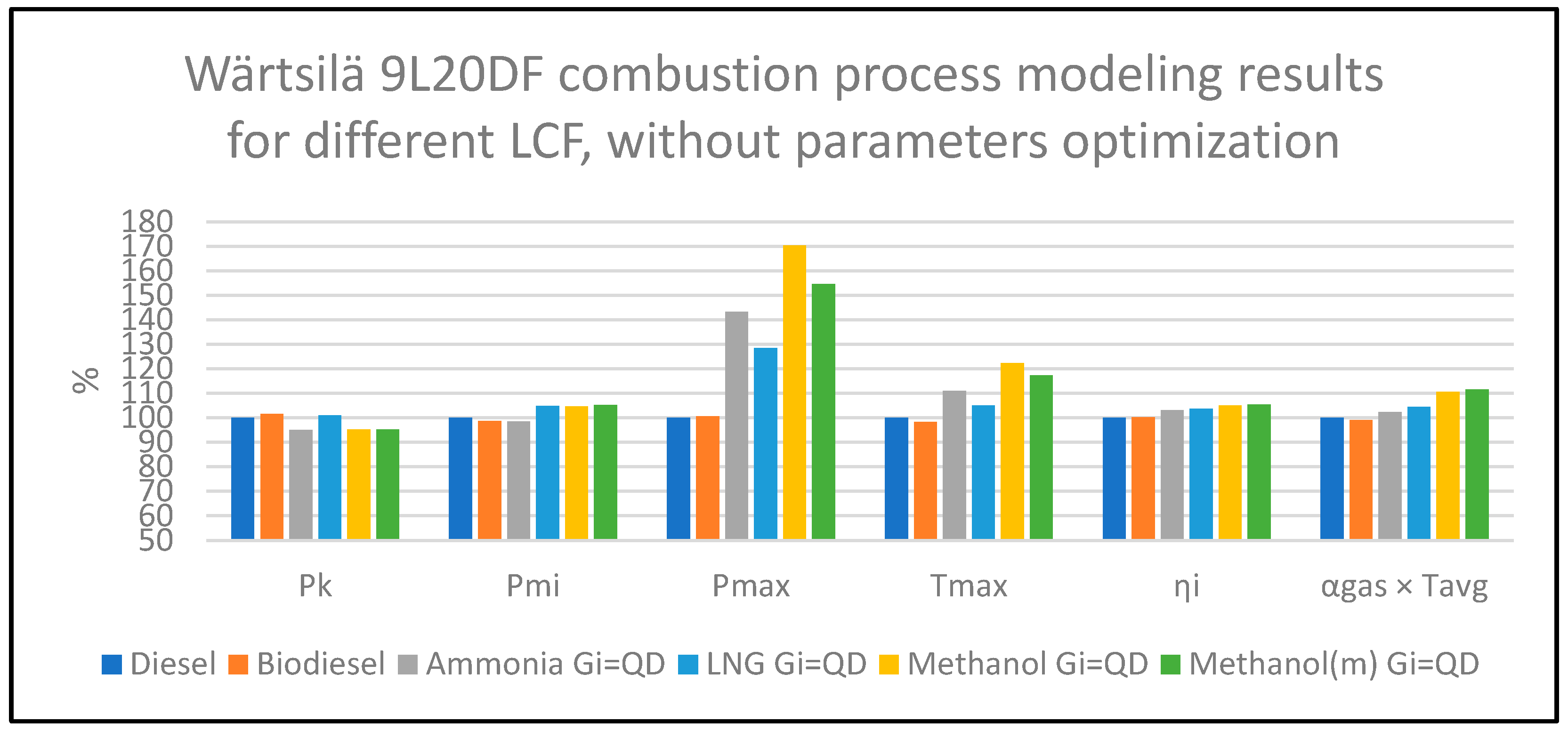
  • In the first stage, the thermal load on the components was evaluated based on the multiplication of αgas av × Tavg, and the mechanical load was assessed using Pmax as an indicator. No changes were made to the adjustment parameters compared to diesel operation. The aim was to assess, through a comparative approach, the thermal and mechanical load factors of components when the engine operates on LCFs versus diesel while identifying effective directions for combustion cycle optimization;
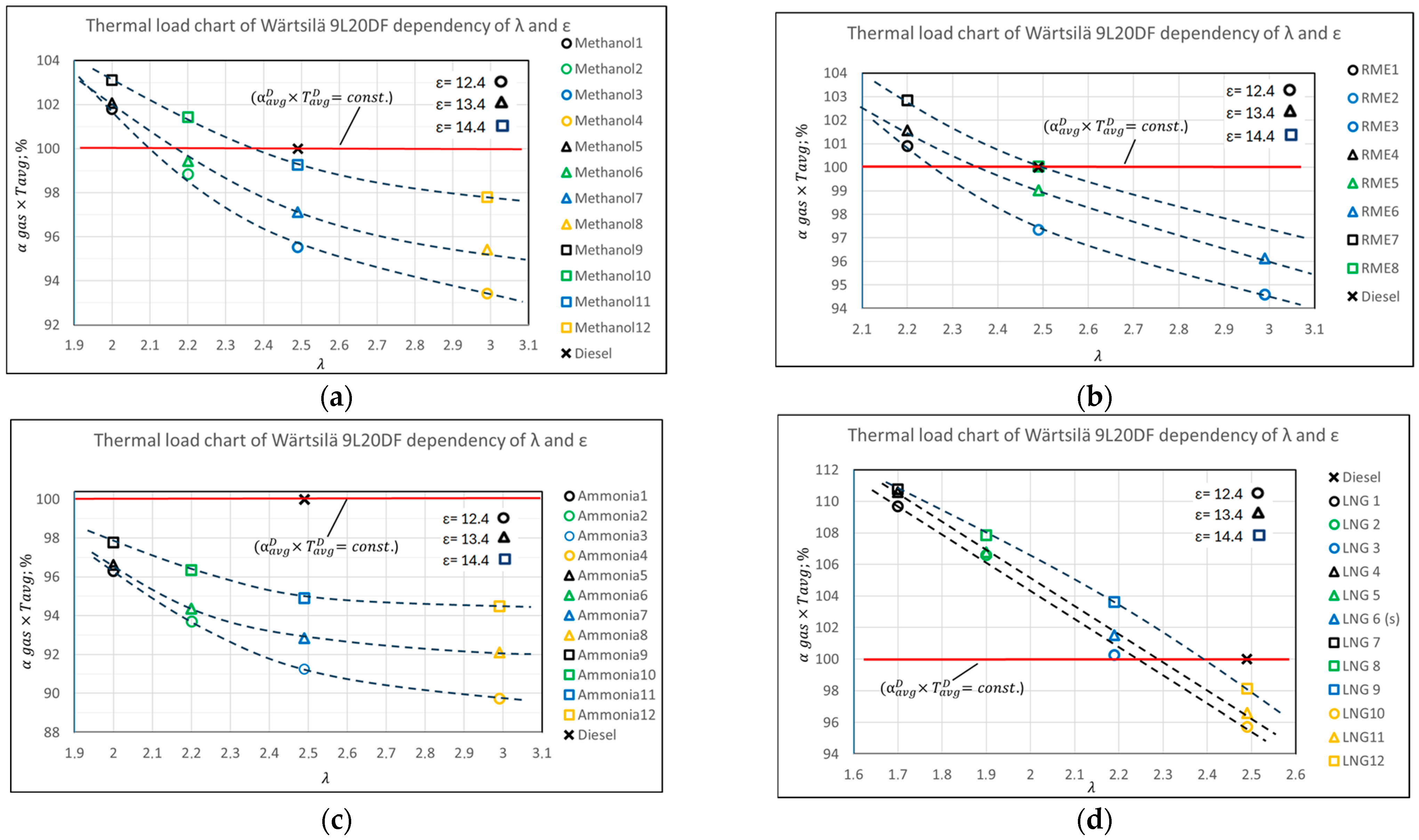
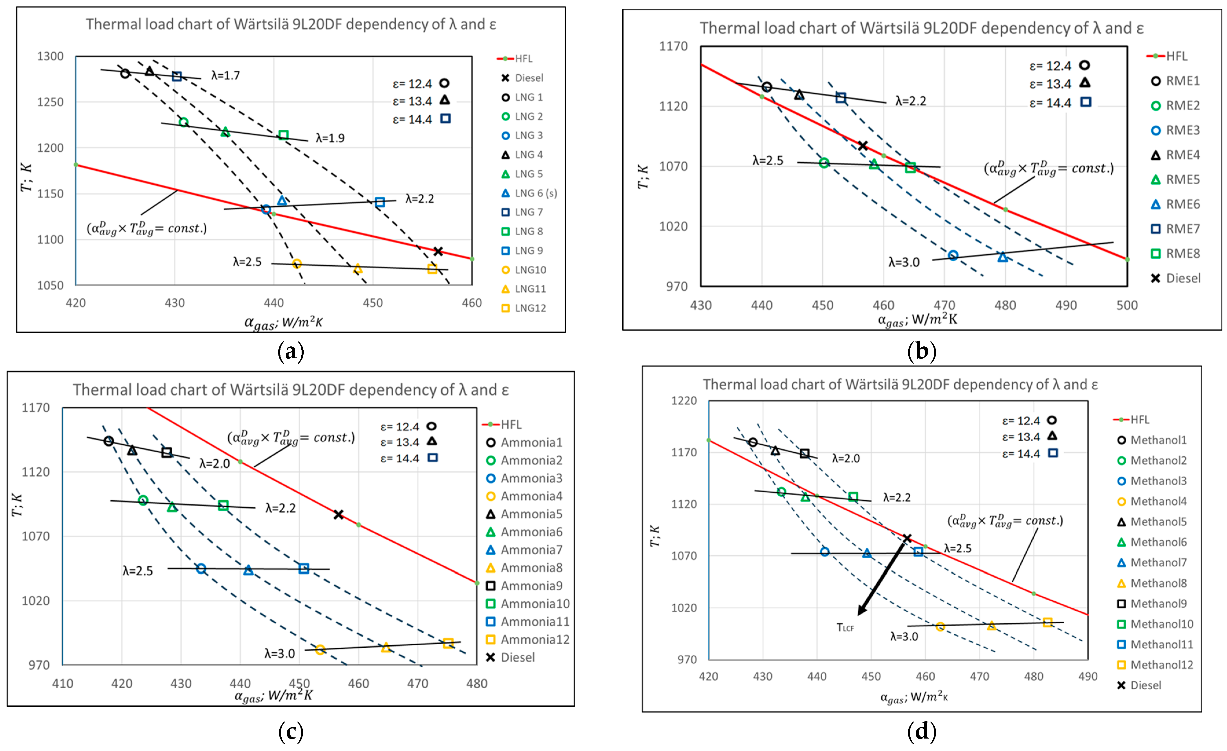
  • In the second stage of the research, a detailed evaluation and optimization of the thermal load were conducted by analyzing the impact of the compression ratio (ε) and the air excess coefficient (λ) in variable models (with Pmax held constant and adjusted by modifying the combustion start angle φcomb). The objective was to validate the effectiveness of these parameters in influencing the thermal load on engine components and to generalize their application using the comparative thermal load evaluation methodology developed in [16]. The comparative assessment was graphically represented in the coordinate system of αgas and T, considering various combinations of (λ, ε)—var (Pmi-idem, Pmax-idem).

3. Results

This study examined two phases of engine conversion to LCF: first, replacing diesel with LCFs without modifying the primary engine adjustment parameters, and second, optimizing the interrelated parameters (ε, λ, φcomb, and Pk).

3.1. Impact of Diesel Replacement with LCFs on Performance Parameters

The studies simulate an initial conversion phase where the engine is converted to LCFs (at Pmi-idem) to evaluate the changes in energy efficiency (ƞi) and mechanical and thermal load factors compared to the parameters specified for diesel operation. The replacement of diesel with LCFs was conducted under the Qf-idem condition, ensuring that the introduced fuel maintained the same energy potential and released an equivalent amount of heat during combustion. Across all evaluated scenarios, the propulsion system’s power output remained constant when operating on LCFs (n = const., based on Pmi, the mean indicated pressure). Compared to the specified load regime, Pmi deviations remained within −1% to −5% (see Table 3 and Figure 2). These findings provide a foundation for identifying effective optimization strategies for adapting operational marine diesel engines to LCFs. The changes in the energy efficiency parameter (ƞi) do not exceed ±0.012 (or 2.5%). However, the mechanical and thermal load factors have significantly increased compared to diesel operation.
The obtained results, excluding biodiesel, indicate that reducing Pmax should be a key objective in combustion cycle optimization.
Methanol. Under equal conditions (ε, λ, and φcomb), the most significant Pmax increase was observed with the use of methanol. Compared to diesel operation, where Pmax is 176 bar, switching to methanol raised Pmax to 301 bar—an increase of 70% (considering direct methanol injection into the cylinder [27,28]). A major factor contributing to the increase in Pmax was the fuel injection method. Studies have shown that direct methanol injection into the cylinder significantly increases Pmax. However, alternative injection strategies—such as port fuel injection (PFI) into the intake manifold or exhaust gas recirculation (EGR)—can help moderate this effect. The use of an EGR system enables a single-phase heat release, which can limit the Pmax increase to 54% (methanol (m) Gi = QD) [28]. When replacing diesel with LCFs at the same λ, the indicator efficiency (ηi) showed the highest increase with methanol under single-phase heat release (5.5%), followed by operation without EGR (4.8%), ammonia (3%), and LNG (−3.3%). For biodiesel, ηi remained comparable to that of diesel. The increase in thermal load on the components (evaluated using the conditional criteria αgas × Tavg) compared to diesel usage was 10.6% for methanol without EGR and 11.6% with EGR.
Ammonia. This study evaluated only the high-pressure direct injection of ammonia into the cylinder, aimed at improving decarbonization performance and reducing harmful emissions [34,35]. As with methanol, a significant increase in Pmax of 43% was observed, reaching 253 bar (compared to 176.7 bar with diesel), while ηi increased to 0.490 (2.5% within the margins of error), and the thermal load on the components increased by 2.3%.
Natural Gas. The Wärtsilä 9L20DF engine is designed to operate on both diesel and LNG, with some data provided in the engine’s technical specifications. Although it is noted in [19] that the engine operates with a reduced λ of 2.1–2.3 in LNG mode (compared to λ = 2.5 for diesel), the modeling for the first phase of this study was performed with λ = 2.5. An increase in λ to 2.5 from the optimal level was associated with increases in all evaluated parameters: Pmax by 28%, and thermal load on components by 4% (from a practical standpoint, changes in Pmi and ƞi are not significant). This significant increase in Pmax requires reducing Pmax and also managing thermal stresses.
Evaluation of the changes in the structural components of the thermal load indicators. The goal of the analysis is to evaluate the importance of mutual changes in structural components of the thermal load ALFA factor due to changes in physical parameters λ p   g a s μ g a s 0.5 and combustion cycle parameters P g a s R g a s     T g a s 0.5 . The data on the changes in the components of the thermal load factor (αgas×Tavg) for the engine operating on LCFs are shown in Table 4.
When directly converting a diesel engine to operate on LCFs, only biodiesel met the comparative criteria affecting the engine’s mechanical reliability, Pmax, and the relative thermal stress criteria (αgas × Tavg), with deviations of both parameters not exceeding 1%. However, the direct use of other fuels without optimization significantly exceeded the established reliability standards (see Table 4 and Figure 2). Based on the adopted strategy (where the results are evaluated comparably), the optimization principle should ensure that the thermal load factor values do not exceed those of diesel operation. The increase in thermal load is caused by changes in both structural parts of the ALFA factor related to higher Pmax and Tavg. Based on this, the hypothesis is proposed that ensuring Pmax-idem equal to diesel operation will have a positive impact on reducing the thermal load (see Section 3.2).

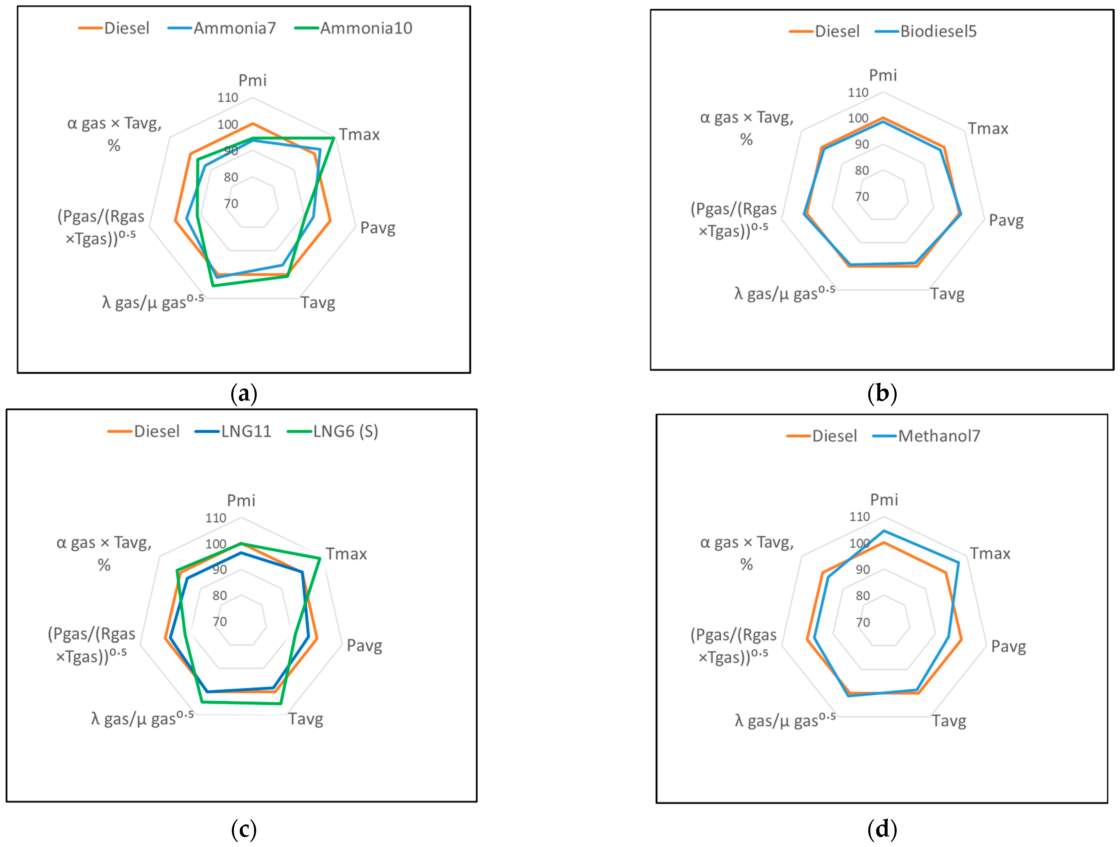
3.2. Optimization of Component Thermal Load Factors

To test the hypothesis, the combustion cycle was optimized by modifying the adjustment parameter (φcomb), ensuring Pmax-idem at the specified level while operating on diesel. Simultaneously, variational simulations of the main combustion cycle parameters (λ, ε, Pk) were conducted to identify the mutual influence of these parameters on factors that affect reliability. This contributes to the development of an informational platform, which serves as one of the components for performing the engine retrofitting to run on LCFs in a comprehensive manner, based on energy, ecological, and reliability indicators. The optimization of combustion cycle parameters involved varying the combinations of λ (adjusting Pk) and ε, ensuring that Pmi and Pmax remain consistent. All the adjustments were made within the engine’s technical specification range (typically ±1 unit). In all test modes, the aim was to maintain the engine’s rated power with an average indicated pressure of Pmi = 23.8 bar. The change in the thermal load factor of the engine components was assessed in two ways: using the conditional heat exchange criteria (αgas × Tavg) and separately considering the heat exchange parameters, αgas and Tavg, by implementing the methodological format created by the authors [16].
A summary of the investigation results is presented in Appendix A Table A1, and Figure 3 illustrates the influence of factors affecting the thermal load on the (αgas × Tavg) criteria in graphical form. The data in Appendix A Table A1 allow for predicting the most efficient retrofitting approach, if necessary, by reducing the thermal load on the components. It also enables the evaluation of the impact of optimizing energy and environmental performance on the thermal load, compared to the diesel option, in the form of (αgas × Tavg) = f(λ, ε), and identifies the rational ranges for changes in variational parameters.
A clear relationship was established between (αgas × Tavg) and the parameters λ and ε, with consistent characteristics observed across all evaluated LCF types (see Figure 3):
  • Increasing the excess air coefficient (λ) led to a continuous decrease in the (αgas × Tavg) criterion for biodiesel and LNG across the entire λ variation range (1.7–2.5). Meanwhile, as (ε) increased, (αgas × Tavg) also increased, indicating a rise in the thermal load on the components;
  • It is important to note that the influence of (λ) on (αgas × Tavg) for methanol and ammonia was not linear: it remained roughly linear up to λ ≈ 2.5 but stabilized asymptotically for λ > 2.5. The main reason for this behavior lies in the difference in the heat release duration (φz) between ammonia and methanol, on the one hand, and biodiesel and LNG, on the other. The combustion duration φz for methanol and ammonia (40–33 crankshaft degrees) was significantly shorter than that of LNG and biodiesel (60–65 crankshaft degrees). As a result, the absolute change in φz at λ ≥ 2.5 had a lesser impact on the indicator diagram and, consequently, on (αgas × Tavg).
Based on the results obtained, an important conclusion regarding the LCF retrofit procedure can be drawn: increasing the λ value of the engine beyond 2.5 is not an effective method for reducing the thermal loads on the components. Moreover, the effectiveness of increasing λ decreased as ε increased, which is typical for modern diesel engine types. For instance, in the conducted studies, at ε = 12.4, increasing λ (up to 2.5) resulted in a ~5% reduction in the (αgas × Tavg) criteria for ammonia, while at ε = 14.4, this reduction decreased to ~2.9%. This suggests that increasing λ for engine conversion to LCF operation is reasonable when applied with acceptable ε values, in line with the criteria for limiting changes in energy and environmental performance. Below are the detailed results of applying the evaluated LCF types instead of diesel fuel based on the heat exchange factor (αgas × Tavg).
Natural Gas. In the studied λ range (1.7–2.2), identified based on the dual-fuel engine manufacturer’s specifications and energy performance improvement studies [19,20], the thermal load criteria exceeded the values observed in the diesel operation mode (see Figure 3). The maximum (αgas × Tavg) increase compared to diesel operation was up to 10.7%. Increasing λ to the diesel level of 2.5 (with ε = 13.4) resulted in a ~3% reduction in (αgas × Tavg) compared to diesel operation. Therefore, for natural gas operation, considering reliability, it is recommended to maintain λ within the upper range of 2.0–2.2, and this should be implemented alongside a reduction in ε.
Biodiesel. In the primary λ range of 2.5–3.0, the thermal load was up to 5% lower than diesel operation with the specified variant. However, at the lower end of the λ range (2.2), (αgas × Tavg) increased by 2–3% compared to diesel operation, with λ and ε reaching the specified values—essentially the same as diesel operation (see Figure 3b).
Ammonia. In the studied λ range of 2.0–3.0, for all tested λ and ε combinations, the (αgas × Tavg) level was 2–10% lower compared to diesel operation (see Figure 3c), creating favorable conditions for retrofitting the engine by focusing the main optimization efforts on improving energy and environmental performance. It should be noted that, in contrast to the combustion cycle modeling for the engine operating on natural gas and biodiesel, the heat release characteristics, as indicated by the I. Wiebe model parameters m and φz did not change with variations in λ. This is because, with a fixed injection phase difference between liquid ammonia and diesel (~7 crankshaft degrees), the phase shift from the top dead center (TDC) is characterized by auto-modeling of fuel combustion, meaning that m and φz remain unchanged [35]. A similar solution with fixed m and φz is characteristic of the evaluation case for methanol use [28]. Changes in the heat release characteristic parameters (from m = 0.5 to 0.8 and φz = 33 to 50 crankshaft degrees, see Table A1) when modeling a lower pressure ammonia injection strategy into the cylinder affected (αgas × Tavg) by no more than ~3%.
Methanol. The distribution of (αgas × Tavg) values in the evaluated range of λ = 2–3 and ε = 12.4–14.4 was symmetrically half of the diesel limit distribution. For a combination of λ and ε similar to diesel, the (αgas × Tavg) criteria value aligned with the specification variant criteria values, showing a ~3% similarity (see Figure 3a). Under the same λ and ε boundary conditions, the engine’s thermal load when operating on methanol was 2.9% lower compared to diesel.
Thus, optimization in the examined λ and ε range, potentially based on the engine’s energy and environmental parameters, is not limited by reliability indicators. The comparative analysis of (αgas × Tavg) = f(λ, ε) provides a foundation for identifying optimal combustion cycle conditions for LCF operation. This includes determining the combinations of excess air coefficient and compression ratio that maintain acceptable thermal and mechanical loads on the components. It would be beneficial to extend the analysis by separately examining the influence of the heat exchange parameters, αgas and Tavg, in comparison to the diesel variant, on the components’ thermal load. This approach will help us better understand the key parameters influencing thermal conditions, specifically the intensity of heat exchange factors, αgas, and the temperature gradient of Tavg (see Figure 4).
In general, the characteristics of all evaluated LCF types showed that the excess air coefficient, as the main performance parameter of the combustion cycle, has an opposite effect on the heat transfer parameters: an increase in λ reduced Tavg, while conversely, it led to an increase in αgas. When λ was kept constant (related to the Pk adjustment), a change in ε, without altering Tavg, directly increased αgas, with this effect becoming more pronounced as λ increased (see Figure 4). The result is determined by the deformation of the combustion cycle’s indicator diagram shape, which is linked to the decrease in Pavg, which in turn affects the ALFA formula (Pgas/(TgasRgas))0.5 component. From a thermodynamic perspective, at Pmax-idem, a decrease in ε reduced the pressure during the compression cycle phase and throughout the combustion cycle, while the λp gas/(μgas)0.5ALFA formula structural component remained virtually unchanged. The identified relationship between the factors influencing thermal load and the control parameters forms the basis for optimizing the engine for LCF operation based on energy and environmental indicators, as well as for optimizing reliability factors.
To verify the obtained research results for the real combustion cycle of LCFs using a single-zone model, it is important to emphasize the positive correlation of these results with the idealized thermodynamic engine cycle, specifically the variational relationships between αgas, Tavg, and the control parameters (ε, λ, Pk, and Tk) [43,57]. The physical justification of the revealed characteristic is determined by the heat release coefficient structure used in the studies, which includes the physical parameters of λp gas and μgas, as well as the thermodynamic parameters of αgas and Tavg, of the working gas in the engine cylinder during heat exchange (see Equation (7)). The structure of Equation (7), with minor ICE research corrections, replicates the classically known analytical expressions for convective heat exchange processes involving the Reynolds (Re), Prandtl (Pr), and Peclet (Pe) numbers, where Re = RenPem [49,50,58]. The common trend observed in all LCF types studied was the change in the structural components of the α-formula λp gas/(μgas)0.5 and (Pgas/(TgasRgas))0.5 when ε- idem: increasing λ led to a decrease in λp gas/(μgas)0.5 and an increase in the structural component of the thermodynamic indicators.
Since the variations in Tavg and αgas exhibited qualitatively identical graphical trends across all evaluated LCF types (see Figure 4), a unified approach to reducing thermal load on components can be established. Based on the gradient principle, the most effective parameter optimization method for minimizing thermal stress involves the interdependent adjustment of λ and ε along the gradient direction (TLCF) from the limiting (αgas × Tavg) diesel reference line (see Figure 4d).
Figure 5 graphically represents the thermal load parameters of the engine after its conversion to LCF operation at Pmax = idem. For biodiesel and methanol, the optimal working cycle parameters in terms of Pmi and ƞi were achieved without exceeding (αgas × Tavg), maintaining the same λ and ε values as in diesel operation. Compared to diesel, the changes in Pmi were −1.4% and +4.5%, while ƞi remained unchanged for biodiesel and decreased by 1.2% for methanol. For LNG, the most efficient operating cycle was identified as LNG6 (S), which, according to [19], is the cycle recommended by the engine manufacturer. In the case of ammonia, the best results were obtained with the Ammonia10 cycle at ε = 14.4 and λ = 2.2, where Pmi decreased by 5.5% and ƞi by 1.2%.
Figure 6 compares different m/φz values for ammonia, confirming that increasing combustion intensity (i.e., reducing combustion duration) not only enhances energy efficiency but also lowers the thermal load on engine components. As shown in the figure, a similar effect can be achieved by increasing the fuel injection pressure, which accelerates the combustion cycle [20,22,35,59,60]. In modern engine designs, rapid and intense fuel combustion is a standard requirement for efficient combustion cycle execution. This principle was notably applied in the development of MTU’s fourth-generation diesel models [58,59]. Although preliminary and requiring further experimental validation, the findings suggest that this approach can further contribute to reducing the thermal load on engine components.
Among other operational measures to reduce thermal load without extensive engine modernization, increasing the cooling of the intake air temperature (Tk) in the intercooler is considered beneficial (typically implemented at 45–60 °C in practice) [53]. By evaluating the physical mechanism of Tk’s influence on the λp gas/(μgas)0.5 and (Pgas/(TgasRgas))0.5 parameters, it is predicted that the position of the (αgas × Tavg) = f(λ, ε) combination mesh in Figure 3 will shift below the (αgas × Tavg) diesel limit line, thereby increasing the thermal load margin for engine components.

4. Discussion of Research Results

The proposed methodology and the results obtained from its application can be used as a tool for evaluating the simultaneous optimization of the combustion cycle based on energy and environmental indicators, as well as changes in thermal and mechanical loads on components during the retrofitting of operating ship fleets for LCF use. This ensures the reliable operation of engines for LCF use. For the practical application of the retrofit, characteristic features for optimizing the combustion cycle for LCF use were revealed:
  • By converting the engine to operate on all of the LCFs evaluated, after ensuring Pmax = idem with diesel, the thermal stress indicator (αgas × Tavg) also approached the permissible limits, similar to when the engine operates on diesel. The temperature factors were approximately 3% lower for methanol, ~7% for ammonia, ~1% for biodiesel, and ~3.5% for LNG (see Table A1 and Figure 3). Increasing the excess air coefficient λ beyond 2.5 units to reduce thermal stresses on components is not rational, as the positive effect of λ on thermal stress diminishes.
  • The influence of the combustion cycle duration on (αgas × Tavg) was revealed: for fuels with relatively short combustion durations, such as ammonia and methanol, the effect on (αgas×Tavg) diminished in the λ ≥ 2.5 range, while for biodiesel and LNG, only a decreasing trend was observed.
To ensure the practical application of the results, it is rational to continue research in two main directions:
  • Alongside the αgas-based structure (widely validated across different diesel engine types), it is important to adapt the αgas formulas from other developers, primarily G. Woschni’s analytically derived expressions, which are approved for various engine fuel types [49,50]. Methodological aspects should be expanded by determining the ALFA formulas for the combustion cycle’s current parameters, Tgas and Pgas;
  • Additionally, it is important to consider that operational indicators are shaped when the engine operates in characteristic cycle modes (e.g., the E3 or E2 test cycle, according to ISO 8178 for ship engines). In this context, it would be beneficial to expand the research to include partial load engine modes, where engines typically operate for extended periods. Thermal and mechanical loads on components should be assessed based on the average values of the operational cycle. When modeling the engine’s combustion cycle characteristics under partial load conditions, it will be necessary to reassess the applicability of G. Woschni’s m and φz recalibration model, taking into account the author’s observations on the inverse relationship between these parameters and λ [61], especially when compared to diesel operation.

5. Conclusions

Assessing the impacts of thermal and mechanical loads when converting existing marine diesel engines to operate with LCFs—particularly those on the cylinder–piston group components—is considered a rational part of the decarbonization challenge in the maritime sector. This approach, alongside energy and environmental optimization, allows for evaluation of the optimal scope and rational directions for necessary retrofitting.
Based on the study of indicators determined for the medium-speed marine engine Wärtsilä 9L20DF and the application of the developed original methodology, the impact of the thermal load on the engine’s cylinder–piston group components was identified when switching from diesel fuel to prospective LCF types: LNG, biodiesel, methanol, and ammonia. Without altering the main engine control parameters (φcomb, Pk, λ, and ε) and operating at rated power, the thermal load on components increased by 2–11%, with the highest increase observed for methanol. Additionally, the peak combustion cycle pressure, which determines the maximum mechanical load level necessary for reliable engine operation, rose significantly: by 23% for LNG, 45% for ammonia (with direct injection), and 72% for methanol (with direct injection). Therefore, the retrofit strategy should initially focus on reducing mechanical loads (based on the Pmax factor), followed by optimizing the factors that influence thermal loads, all while maintaining constant Pmax conditions.
The indicator of the energy efficiency of the combustion cycle—the useful work coefficient (ƞi)—improved by 3–5% in correspondence with the increase in the cycle dynamics (Pmi), thus creating a reserve for further optimization of the control parameters while maintaining the specific fuel consumption.
The structural analysis of the thermal load factors showed that, except for biodiesel, the thermal load on the components increased as both the characteristic temperature Tavg and the heat transfer coefficient αgas increased. In addition, the influence of the two structural components of αgas increased: the components characterized the thermodynamic parameters of the working body (Pgas/(TgasRgas))0.5 and the components of the physical properties λp gas/(μgas)0.5 in a manner dependent on the thermodynamic parameters (Tgas, Pgas). Based on this, a hypothesis is proposed regarding the priority of reducing thermal loads on components while ensuring the set Pmax value, which gains additional confirmation.
The proposed strategy suggests that, in order to maintain component loads similar to those when the engine operates on diesel and reduce Pmax to the specified values, it is rational to keep the values of λ and ε constant (while optimizing Pk and φcomb). This approach ensures that the thermal load on the components remains close to that during diesel operation (αgas × Tavg).
In the proposed retrofitting stage, without deep structural modernization, the greatest regulatory effect on component thermal loads (while ensuring Pmax = idem) was achieved by improving the air supply (λ) up to a set rational limit of 2.5 units and reducing the compression ratio, taking into account fuel consumption and ensuring a “cold” state engine start.

Author Contributions

Conceptualization, S.L. and E.M.; methodology, S.L.; software, E.M.; formal analysis, S.L. and E.M.; investigation, E.M.; data curation, S.L.; writing—original draft preparation, E.M.; writing—review and editing, S.L.; visualization, E.M.; supervision, S.L.; funding acquisition, S.L. All authors have read and agreed to the published version of the manuscript.

Funding

This research was funded by the Research Council of Lithuania and the Ministry of Education, Science and Sport of Lithuania (Contract No. S-A-UEI-23-9).

Institutional Review Board Statement

Not applicable.

Informed Consent Statement

Not applicable.

Data Availability Statement

Data are contained within the article.

Acknowledgments

The authors would like to thank the Klaipeda University Faculty of Marine Technology and Natural Sciences for their support.

Conflicts of Interest

The funders had no role in the design of the study; in the collection, analyses, or interpretation of data; in the writing of the manuscript; or in the decision to publish the results.

Abbreviations

The following abbreviations are used in this manuscript:
LCFlow carbon fuels;
GHGgreenhouse gas;
IMOInternational Maritime Organization;
LNGliquified natural gas;
MMmathematical model;
ICEinternal combustion engine;
TDCtop dead center;
PFIport fuel injection;
LHVlower heating value;
CADcrank angle degrees;
CPGcylinder–piston group;
EGRexhaust gas recirculation;
TEthermal efficiency;
HDDFhigh-density dual fuel;
SOPIstart of pre-injection;
ROPIratio of pre-injection;
BTDCbefore top dead center;
CA50crank angle at which 50% of the heat from combustion is released;
CA90crank angle at which 90% of the heat from combustion is released;
CO2carbon dioxide;
CH4methane;
N2Odinitrogen oxide;
NOxnitrous oxides;
Tmaxmaximum combustion cycle temperature (K);
Tkmanifold air temperature (K);
Tavgcombustion average temperature (K);
Pmaxmaximum combustion cycle pressure (bar);
Pavgcombustion average pressure (bar);
Pmimean indicated pressure (bar);
Pmebreak mean effective pressure (bar);
Pkmanifold air pressure (bar);
Gifuel injection portion;
ƞiuseful work coefficient;
φzcombustion duration (CA°);
φinjfuel injection crank angle
φcombstart of combustion (CA°);
mheat release form factor;
λair fuel ratio;
αgas avheat load coefficient during the cycle;
εengine compression ratio;

Appendix A

Table A1. Experiment results.
TestAdjustable ParametersMathematical Modeling ResultsCalculation
εφcombλm/φzPkPmiPmaxTmaxPavgTavgƞiλp gas/(μgas)0.5αgasαgas × Tavg. %
Diesel 13.4−62.51.1/654.423.8177158665.710870.481.11457100
LNG 112.4−81.70.5/603.023.5177201354.012810.471.25425109.7
LNG 212.4−61.90.5/603.423.7178172356.212280.471.22431106.6
LNG 312.4−32.20.5/603.923.9179172659.811330.471.15439100.3
LNG 413.4−51.70.5/603.023.7177200654.612840.471.26427110.6
LNG 5 13.4−31.90.5/603.423.8178187657.312180.471.21435106.8
LNG 6 (s)13.402.20.5/603.923.8176172360.111430.471.16441101.5
LNG 714.4−21.70.5/603.023.7174197455.312780.471.25430110.8
LNG 814.4−11.90.5/603.423.9179185958.812140.471.21441107.9
LNG 914.422.20.5/603.923.8176170862.811410.471.16451103.6
LNG1012.4−22.50.5/604.223.0180161261.710740.481.1144295.7
LNG1113.412.50.5/604.223.0177159063.410690.481.1144896.6
LNG1214.432.50.5/604.222.9177157665.510680.471.1145698.1
RME112.4−112.21.1/653.923.5175170160.311360.481.14441100.9
RME212.4−82.51.1/654.423.4174157263.910730.471.1045097.3
RME312.4−43.01.1/655.323.1177141170.69960.471.0647194.6
RME413.4−82.21.1/653.923.5174167361.811300.481.14446101.6
RME513.4−62.51.1/654.423.5178155866.210720.481.1045899.0
RME613.4−13.01.1/655.322.8178139273.09950.461.0648096.1
RME714.4−62.21.1/653.923.5176165763.711270.481.14453102.8
RME814.4−32.51.1/654.423.2175153567.910690.471.10464100.0
RME914.403.01.1/605.323.2194139976.610040.461.0649199.3
Ammonia112.402.00.5/333.322.2179184753.611440.461.2041896.3
Ammonia212.422.20.5/333.722.3179175356.010980.471.1642493.7
Ammonia312.452.50.5/334.122.3175163859.310450.461.1243391.3
Ammonia412.483.00.5/334.922.1175150165.59820.461.0845489.7
Ammonia513.432.00.5/333.322.3177182754.611370.471.2042296.6
Ammonia613.452.20.5/333.722.3175173457.310930.471.1642894.4
Ammonia713.472.50.5/334.122.3175162961.410440.471.1244192.8
Ammonia7a13.4−12.50.8/504.122.3177157162.510490.471.1344594.1
Ammonia813.493.00.5/334.922.3181150168.79840.471.0846592.1
Ammonia914.452.00.5/333.322.4176181656.111350.471.1942897.8
Ammonia1014.462.20.5/333.722.5180173359.510940.471.1643796.4
Ammonia1114.482.50.5/334.122.4179162864.010450.471.1245194.9
Ammonia1214.4103.00.5/334.922.4184150071.79870.471.0847594.5
Methanol112.4−12.00.5/403.324.7177191154.911800.471.20428101.8
Methanol212.412.20.5/403.724.8175181157.211320.471.1743398.9
Methanol312.442.50.5/404.124.8177169460.410740.471.1244195.5
Methanol412.473.00.5/405.024.7178153767.210020.471.0846393.4
Methanol513.422.00.5/403.324.9179189856.011720.471.20432102.1
Methanol613.442.20.5/403.724.9177179858.411270.471.1643899.4
Methanol713.462.50.5/404.124.9177168362.510730.471.1244997.1
Methanol813.493.00.5/405.024.7178152869.910030.471.0847295.4
Methanol914.442.00.5/403.325.0179188357.411690.471.19438103.1
Methanol1014.452.20.5/403.724.9175178560.711270.471.16447101.4
Methanol1114.472.50.5/404.124.8175167165.110740.471.1245999.3
Methanol1214.4103.00.5/405.024.8182152572.910060.471.0848397.8
Ammonia Gi = QD13.4−62.50.8/504.122.9206162265.510600.481.1345697.5
Ammonia Gi = QD13.4−62.50.5/334.123.5253175969.710770.491.14472102.3
Methanol(m) Gi = QD13.4−62.50.4/304.125.0273186072.711140.501.16497111.6
Methanol Gi = QD13.4−62.50.2/174.124.9301194075.511280.501.15487110.6
LNG Gi = QD13.4−62.50.5/604.424.9227166670.910870.491.13477104.5

References

  1. International Maritime Organization. 2023 IMO Strategy on Reduction of GHG Emissions from Ships. Available online: https://www.imo.org/en/OurWork/Environment/Pages/2023-IMO-Strategy-on-Reduction-of-GHG-Emissions-from-Ships.aspx (accessed on 9 February 2025).
  2. European Commission. COM (2021) 562 Final 2021/0210 (COD). 2021. Available online: https://opac.oireachtas.ie/Data/Library3/Documents%20Laid/2021/pdf/TRAdocslaid110821_110821_152830.pdf (accessed on 9 February 2025).
  3. International Maritime Organization. Mandatory IGF Code for Ships Using Gases or Other Low-Flashpoint Fuels Enters into Force on 1 January 2017, Along with New Training Requirements for Seafarers Working on Those Ships. Available online: https://www.imo.org/en/MediaCentre/PressBriefings/Pages/01-IGF.aspx (accessed on 22 March 2025).
  4. DNV. Exploring All Options to Keep Decarbonization on Course. Available online: https://www.dnv.com/expert-story/maritime-impact/exploring-all-options-to-keep-decarbonization-on-course/ (accessed on 9 February 2025).
  5. DNV. Achieving the IMO Decarbonization Goals. Containership Insights. MARITIME IMPACT. 23 July 2020. Available online: https://www.dnv.com/expert-story/maritime-impact/How-newbuilds-can-comply-with-IMOs-2030-CO2-reductiontargets.html (accessed on 10 December 2023).
  6. International Maritime Organization. EEXI and CII—Ship Carbon Intensity and Rating System. Available online: https://www.imo.org/en/MediaCentre/HotTopics/Pages/EEXI-CII-FAQ.aspx (accessed on 22 March 2025).
  7. Langari, J.; Aliakbari, K.; Nejad, R.M. Failure analysis of CK45 steel crankshaft in light truck diesel engine. Eng. Fail. Anal. 2023, 145, 107045. [Google Scholar] [CrossRef]
  8. Venkatachalam, G.; Kumaravel, A. Experimental Investigations on the Failure of Diesel Engine Piston. Mater. Today Proc. 2019, 16, 1196–1203. [Google Scholar] [CrossRef]
  9. Lu, Y.; Zhang, X.; Xiang, P.; Dong, D. Analysis of thermal temperature fields and thermal stress under steady temperature field of diesel engine piston. Appl. Therm. Eng. 2017, 113, 796–812. [Google Scholar] [CrossRef]
  10. Cabuk, A.S. Experimental IoT study on fault detection and preventive apparatus using Node-RED ship’s main engine cooling water pump motor. Eng. Fail. Anal. 2022, 138, 106310. [Google Scholar] [CrossRef]
  11. Suthisripok, T.; Semsamran, P. The impact of biodiesel B100 on a small agricultural diesel engine. Tribol. Int. 2018, 128, 397–409. [Google Scholar] [CrossRef]
  12. Chang, J.; Güralp, O.; Filipi, Z.; Assanis, D.; Kuo, T.W.; Najt, P.; Rask, R. New Heat Transfer Correlation for an HCCI Engine Derived from Measurements of Instantaneous Surface Heat Flux. SAE Trans. 2004, 113, 1576–1593. [Google Scholar] [CrossRef]
  13. Wu, Y.Y.; Chen, B.C.; Hsieh, F.C.; Ke, C.T. Heat transfer model for small-scale spark-ignition engines. Int. J. Heat Mass Transf. 2009, 52, 1875–1886. [Google Scholar] [CrossRef]
  14. Rabeti, M.; Ranjbar, A.A.; Jahanian, O.; Ardebili, S.M.S.; Solmaz, H. Investigation of important semi-empirical heat transfer models for a natural gas fueled HCCI engine. Energy Rep. 2021, 7, 8652–8666. [Google Scholar] [CrossRef]
  15. International Maritime Organization. Unified Interpretations to MARPOL ANNEX VI. MEPC.1/Circ.795/Rev.6. 2022. Available online: https://wwwcdn.imo.org/localresources/en/OurWork/Environment/Documents/Air%20pollution/MEPC.1-Circ.795-Rev.6.pdf (accessed on 19 February 2025).
  16. Lebedevas, S.; Milasius, E. Methodological Aspects of Assessing the Thermal Load on Diesel Engine Parts for Operation on Alternative Fuel. J. Mar. Sci. Eng. 2024, 12, 325. [Google Scholar] [CrossRef]
  17. Benson, R.S.; Whitehouse, N.D. Combustion in Compression Ignition Engines. In Internal Combustion Engines; Pergamon: Bergama, Turkey, 1979; pp. 69–95. [Google Scholar] [CrossRef]
  18. Merker, G.P.; Schwarz, C.; Stiesch, G.; Otto, F. Simulating Combustion—Simulation of Combustion and Pollutant Formation for Engine-Development; Springer: Berlin/Heidelberg, Germany, 2006; pp. 148–155. [Google Scholar]
  19. Stoumpos, S.; Theotokatos, G.; Boulougouris, E.; Vassalos, D.; Lazakis, I.; Livanos, G. Marine dual fuel engine modelling and parametric investigation of engine settings effect on performance-emissions trade-offs. Ocean Eng. 2018, 157, 376–386. [Google Scholar] [CrossRef]
  20. Ao, X.; Gan, H.; Xin, M.; Cong, Y.; Lu, D.; Guo, A.; Wang, H. Numerical investigation on the effects of pilot fuel and natural gas injection pressures on methane slip in a large marine dual-fuel engine. Energy 2024, 312, 133675. [Google Scholar] [CrossRef]
  21. International Maritime Organization. LNG Bunkering Development. Available online: https://futurefuels.imo.org/home/future-insight/alternative-fuels/scalability-and-sustainability/lng/ (accessed on 10 February 2025).
  22. Yang, D.; Wei, S.; Ma, Y.; Jiaqiang, E.; Zhao, J. Influence of critical parameters on combustion and emission characteristics of methanol/diesel dual fuel compression combustion engine. Fuel 2024, 368, 131647. [Google Scholar] [CrossRef]
  23. Chen, H.; Su, X.; He, J.; Xie, B. Investigation on combustion and emission characteristics of a common rail diesel engine fueled with diesel/n-pentanol/methanol blends. Energy 2019, 167, 297e311. [Google Scholar] [CrossRef]
  24. Deka, T.J.; Abd, M.E.; Osman, A.I.; Ali, R.I.; Baruah, D.C.; Rooney, D.W. Optimising novel methanol/diesel blends as sustainable fuel alternatives: Performance evaluation and predictive modelling. Energy Convers. Manag. 2024, 321, 118943. [Google Scholar] [CrossRef]
  25. Wei, F.; Zhang, Z.; Wei, W.; Zhang, H.; Cai, W.; Dong, D.; Li, G. Multi-objective optimization of the performance for a marine methanol-diesel dual-fuel engine. Fuel 2024, 368, 131556. [Google Scholar] [CrossRef]
  26. Jiang, M.; Sun, W.; Guo, L.; Zhang, H.; Jis, Z.; Qin, Z.; Zhu, G.; Yu, C.; Zhang, J. Numerical optimization of injector hole arrangement for marine methanol/diesel direct dual fuel stratification engines. Appl. Therm. Eng. 2024, 257, 124456. [Google Scholar] [CrossRef]
  27. Lv, J.; Sun, Y.; Zhang, Z.; Fang, Y. Optimization of operational parameters of marine methanol dual-fuel engine based on RSM-MOPSO. Process Saf. Environ. Prot. 2024, 191, 2634–2652. [Google Scholar] [CrossRef]
  28. Karvounis, P.; Theotokatos, G.; Patil, C.; Xiang, L.; Ding, Y. Parametric investigation of diesel–methanol dual fuel marine engines with port and direct injection. Fuel 2025, 381, 133441. [Google Scholar] [CrossRef]
  29. Wang, H.; Chang, Y.; Sun, K.; Jis, M.; Wang, T. Development of a reduced chemical kinetic mechanism for ammonia/diesel combustion over a wide range of ammonia energy ratios. Fuel 2025, 381, 133536. [Google Scholar] [CrossRef]
  30. Cheng, H.; Tang, Q.; Uddeen, K.; Huang, L.; Zheng, Z.; Turner, J.; Yao, M. The ignition mechanisms and chemical reaction kinetics of nitrogen oxide of ammonia/diesel dual-fuel engine combustion. Appl. Therm. Eng. 2024, 262, 125287. [Google Scholar] [CrossRef]
  31. Nie, X.; Bi, Y.; Shen, L.; Lei, J.; Wan, M.; Xiao, Y.; Chen, G. Experimental study for optimizing EGR strategy in an ammonia-diesel dual-fuel engine under different altitudes. Energy 2024, 313, 133953. [Google Scholar] [CrossRef]
  32. Zhang, J.; Chen, D.; Li, X.; Li, J.; Huang, H.; Kobayashi, N. Large eddy simulation of ammonia-diesel dual fuel spray combustion: Effects of ambient condition on ignition characteristics. Che. Eng. J. 2024, 501, 157698. [Google Scholar] [CrossRef]
  33. Zhang, J.; Zhao, Z.; Mohammed, A.E.; Dong, S.; Wang, S.; Ouyang, W.; Zhang, C.; Cheng, X. On ammonia/diesel dual-fuel combustion in optical engine. Fuel 2024, 367, 131452. [Google Scholar] [CrossRef]
  34. Zuo, Q.; Chen, L.; Chen, W.; Zhu, G.; Wang, z.; Ma, Y.; Shen, Z.; Lu, C. Performance analysis of ammonia energy ratio on an ammonia-diesel engine in different fuel supply modes. Fuel 2025, 384, 134038. [Google Scholar] [CrossRef]
  35. Drazdauskas, M.; Lebedevas, S. Numerical Study on Optimization of Combustion Cycle Parameters and Exhaust Gas Emissions in Marine Dual-Fuel Engines by Adjusting Ammonia Injection Phases. J. Mar. Sci. Eng. 2024, 12, 1340. [Google Scholar] [CrossRef]
  36. Lebedevas, S.; Lebedeva, G.; Gudaityte, I. Research of characteristics of working cycle of high-speed diesel engine operating on biofuels RME–E and D–RME–E. Part 1. Indicators of fuel injection system and indicative process. Transport 2013, 28, 204–213. [Google Scholar] [CrossRef]
  37. Ahmadi, M.G.; Shun, C.C.; Yung, K. Comparison between blended mode and fumigation mode on combustion, performance and emissions of a diesel engine fueled with ternary fuel (diesel- biodiesel- ethanol) based on engine speed. J. Energy Inst. 2019, 92, 1233e1250. [Google Scholar] [CrossRef]
  38. Wai, P.; Kanokkhanarat, P.; Oh, B.; Wongpattharaworakul, V.; Depaiwa, N.; Po-ngaen, W.; Chollacoop, N.; Srisurangkul, C.; Kosaka, H.; Yamakita, M.; et al. Experimental investigation of the influence of ethanol and biodiesel on common rail direct injection diesel Engine’s combustion and emission characteristics. Case Stud. Therm. Eng. 2022, 39, 102430. [Google Scholar] [CrossRef]
  39. Karin, P.; Tripatara, A.; Wai, P.; Oh, B.; Charoenphonphanich, C.; Chollacoop, N.; Kosaka, H. Influence of ethanol-biodiesel blends on diesel engines combustion behavior and particulate matter physicochemical characteristics. Case Stud. Chem. Environ. Eng. 2022, 6, 100249. [Google Scholar] [CrossRef]
  40. Blasio, D.G. Clean Fuels for Mobility; Springer: Singapore, 2022; pp. 39–179. [Google Scholar]
  41. Torres, D.J.; Li, Y.H.; Kong, S. Partitioning strategies for parallel KIVA-4 engine simulations. Comput. Fluids 2010, 39, 301–309. [Google Scholar] [CrossRef]
  42. Forgber, T.; Tosona, P.; Madlmeir, S.; Kureck, H.; Khinast, J.G.; Jajcevic, D. Extended validation and verification of XPS/AVL-Fire™, a computational CFD-DEM software platform. Powder Technol. 2020, 361, 880–893. [Google Scholar] [CrossRef]
  43. Lebedevas, S.; Pukalskas, S.; Daukšys, V. Mathematical modelling of indicative process parameters of dual-fuel engines with conventional fuel injection system. Transport 2020, 35, 57–67. [Google Scholar] [CrossRef]
  44. Lebedevas, S.; Cepaitis, T. Methodological Solutions for Predicting Energy Efficiency of Organic Rankine Cycle Waste Heat Recovery Systems Considering Technological Constraints. J. Mar. Sci. Eng. 2024, 12, 1303. [Google Scholar] [CrossRef]
  45. Duc, T.H.; Nhat, B.N.; Tan, P.T.; Hoang, S.D.; Quang, M.P.; Viet, T.V. Application of AVL BOOST modeling to optimize the engine working load and drivetrain transmission ratio of the diesel firefighting pump system. Heliyon 2024, 10, e41029. [Google Scholar] [CrossRef]
  46. Qadiri, U.; Alfantazi, A. Numerical 1-D simulations on Single-Cylinder stationary spark ignition engine using Micro-Emulsions, gasoline, and hydrogen in dual fuel mode. Cleaner Chem. Eng. 2022, 2, 100009. [Google Scholar] [CrossRef]
  47. Konkov, A. Diagnostics of Diesel Engine Technical Condition in Operation on the Basis of Identification of Fast Operating Processes; Admiral G.I. Nevelskoy Maritime State University: Vladivostok, Russia, 2011. [Google Scholar]
  48. Wiebe, I.I. The New About Working Cycle of the Engine; Mashgiz: Moscow, Russia, 1962; 271p. [Google Scholar]
  49. Woschni, G.; Anists, F. A method for predicting the change in the combustion process of medium-speed diesel engines under changed operating conditions. MTZ 1973, 4, 106–110. [Google Scholar]
  50. Woschni, G. The calculation of wall losses and the thermal load of diesel engines. MTZ 1970, 31, 491–499. [Google Scholar]
  51. Molodtsov, N.I.; Sokolov, P.V.; Vlasov, Y.Y. The influence of structural regulation indicators and augmentation level on heat release coefficient of gases to the surface of CPG parts. Leningr. CDERI Proc. 1975, 69, 3–17. [Google Scholar]
  52. Woschni, G. A Universally Applicable Equation for the Instantaneous Heat Transfer Coefficient in the Internal Combustion Engine; SAE Technical Paper; SAE International: Warrendale, PA, USA, 1967; p. 670931. [Google Scholar]
  53. Wärtsilä. Available online: https://www.wartsila.com/marine/products/engines-and-generating-sets/wartsila-20 (accessed on 22 March 2025).
  54. Zinner, K. Results of real cycle calculations about the possibilities of influencing the efficiency of diesel engines. MTZ 1970, 31, 243–246. [Google Scholar]
  55. Stechkin, B.S. On the efficiency of an ideal fast combustion cycle at a finite rate of heat release. Theory, design, calculation and testing of internal combustion engines. Proc. Lab. Engines USSR Acad. Sci. 1960, 1, 61–67. [Google Scholar]
  56. Semenov, B.N.; Ivanchenko, N.N. Problems of increasing the fuel efficiency of diesel engines and ways to solve them. Engine Eng. 1990, 11, 3–7. [Google Scholar]
  57. Lebedevas, S.; Lebedeva, G.; Pikūnas, A.; Spruogis, B. A simultaneous parametric analysis of the in-cylinder processes for diesel engines. Int. J. Veh. Syst. 2011, 18, 18–45. [Google Scholar] [CrossRef]
  58. Kirkpatrick, A.T. Heat and Mass Transfer. In Internal Combustion Engines: Applied Thermosciences; John Wiley & Sons: Hoboken, NJ, USA, 2020; Volume 11. [Google Scholar] [CrossRef]
  59. Kruggel, O. Progress in the combustion technology of high performance diesel engines toward reduction of exhaust emissions without reduction of operation economy. In Proceedings of the Baden–Wurttemberg Technology Conference, Westborough, MA, USA, 2–14 June 1989; p. 14. [Google Scholar]
  60. Kruggel, O. Investigations into nitrogen oxide reduction on high-speed large diesel engines. MTZ Mot. 1988, 49, 22–29. [Google Scholar]
  61. Lebedevas, S.; Raslavičius, L.; Drazdauskas, M. Comprehensive correlation for the prediction of the heat release characteristics of diesel/CNG mixtures in a single-zone combustion model. Sustainability 2023, 15, 3722. [Google Scholar] [CrossRef]
Figure 1. Research plan for the thermal and mechanical load factors of the components of a marine diesel engine while operating on LCFs.
Jmse 13 00748 g001
Figure 2. Impact of switching from diesel to LCFs on the Wärtsilä 9L20DF engine performance with ε and λ set to diesel values.
Jmse 13 00748 g002
Figure 3. Dependence (αgas × Tavg) = f(λ,ε,) for different LCFs (Pmax = cons): (a) methanol; (b) biodiesel; (c) ammonia; (d) LNG.
Jmse 13 00748 g003
Figure 4. Reducing the thermal load factor potential of the Wärtsilä 9L20DF engine by optimizing the λ-ε parameters: (a) LNG; (b) biodiesel; (c) ammonia; and (d) methanol.
Jmse 13 00748 g004
Figure 5. Comparison of thermal load parameter rates on the components of the Wärtsilä 9L20DF engine operating on LCFs (Pmax = idem) versus diesel: (a) ammonia, (b) biodiesel, (c) LNG, and (d) methanol.
Jmse 13 00748 g005
Figure 6. Thermal load dependence on the combustion cycle parameters (m and φz) for ammonia.
Jmse 13 00748 g006
Table 1. Comparison of the physicochemical properties of fuel types.
Fuel TypeAmmoniaMethanolBiodiesel (RRME)LNGDiesel
Chemical formula NH3CH3OHCH3(CH2)nCOOCH3CH4-
Density when liquefied, kg/m3602.8792890430832
Lower calorific value, MJ/kg18.519.937.538.142.7
Octane number11010960.6107-
Cetane number5–75–8>51-47–55
Ignition temperature, °C651385>150540254–285
Flame spread rate, m/s0.07–0.140.50-0.380.87
Heat of vaporization, kJ/kg13701103300510250–290
C, mass fraction0.037.577.075.086.7
H, mass fraction17.712.612.125.013.3
O, mass fraction0.049.910.90.00.0
N, mass fraction82.30.00.00.00.0
Table 2. Wärtsilä 9L20DF technical data.
Wärtsilä 9L20DFAE/DEME
Gas modeDiesel modeGas modeDiesel mode
Cylinder outputkW180
Engine speedrpm1200
Speed mode ConstantVariable
Engine outputkW1665
Cylinder boremm200
Strokemm280
Compression ratio 13.4
Piston displacementl/cyl8.8
Table 3. Diesel replacement with LCFs simulation results on performance parameters (ε and λ equal).
TestParameters
Pk, barPmi, barPmax, barTmax, Kηiαgas × Tavg, %
Diesel4.3523.8176.715860.476100.0
Biodiesel4.4223.5177.915580.47699.0
Ammonia Gi = QD4.1323.5253.217590.490102.3
Methanol Gi = QD4.1424.9301.019400.499110.6
Methanol (m) Gi = QD4.1425.0273.118600.502111.6
LNG Gi = QD4.3924.9226.916660.493104.5
Table 4. Changes in thermal load factor components (αgas × Tavg).
TestPavgTavg(λgas/μgas)0.5(Pgas/(Rgas × Tgas))0.5αgasαgas × Tavg, %
Diesel65.710871.1114.48457100.0
Biodiesel66.210721.1014.6445899.0
Ammonia Gi = QD69.710771.1414.51472102.3
Methanol Gi = QD72.711141.1615.09497110.6
Methanol (m) Gi = QD75.511281.1514.89487111.6
LNG Gi = QD70.910871.1314.89477104.5
Disclaimer/Publisher’s Note: The statements, opinions and data contained in all publications are solely those of the individual author(s) and contributor(s) and not of MDPI and/or the editor(s). MDPI and/or the editor(s) disclaim responsibility for any injury to people or property resulting from any ideas, methods, instructions or products referred to in the content.

