Review

A Survey on the Design and Mechanical Analysis of Cryogenic Hoses for Offshore Liquid CO2 Ship-to-Ship Transfer

1
Research and Development Center, CNOOC Gas & Power Group Co., Ltd., Beijing 100010, China
2
CNOOC Key Laboratory of Liquefied Natural Gas and Low-Carbon Technology, Beijing 100028, China
3
State Key Laboratory of Structural Analysis for Industrial Equipment, School of Mechanics and Aerospace Engineering, Dalian University of Technology, Dalian 116024, China
4
Department of Ocean Science and Technology, Dalian University of Technology, Panjin 124221, China
5
Ningbo Institute of Dalian University of Technology, Ningbo 315016, China
*
Authors to whom correspondence should be addressed.
J. Mar. Sci. Eng. 2025, 13(4), 790; https://doi.org/10.3390/jmse13040790
Submission received: 28 February 2025 / Revised: 7 April 2025 / Accepted: 10 April 2025 / Published: 16 April 2025
(This article belongs to the Section Coastal Engineering)

Abstract

:
With the increasing severity of climate change, Carbon Capture, Utilization, and Storage (CCUS) technology has become essential for reducing atmospheric CO2. Marine carbon sequestration, which stores CO2 in seabed geological structures, offers advantages such as large storage capacity and high stability. Cryogenic hoses are critical for the ship-to-ship transfer of liquid CO2 from transportation vessels to offshore carbon sequestration platforms, but their design methods and mechanical analysis remain inadequately understood. This study reviews existing cryogenic hose designs, including reinforced corrugated hoses, vacuum-insulated hoses, and composite hoses, to assess their suitability for liquid CO2 transfer. Based on CO2’s physicochemical properties, a conceptual composite hose structure is proposed, featuring a double-spring-supported internal composite hose, thermal insulation layer, and outer sheath. Practical recommendations for material selection, corrosion prevention, and monitoring strategies are provided to improve flexibility, pressure resistance, and thermal insulation, enabling reliable long-distance tandem transfer. A mechanical analysis framework is developed to evaluate structural performance under conditions including mechanical loads, thermal stress, and dynamic responses. This manuscript includes an introduction to the background, the methodology for data collection, a review of existing designs, an analysis of CO2 characteristics, the proposed design methods, the mechanical analysis framework, a discussion of challenges, and the conclusions.

1. Introduction

The rapid development of the global economy has led to a sharp increase in greenhouse gas emissions, exacerbating climate change. Rising temperatures, frequent extreme weather events, and rising sea levels pose serious challenges to the sustainable development of human society. In response to these issues, governments worldwide have set carbon reduction targets and actively promoted the implementation and development of Carbon Capture, Utilization, and Storage (CCUS) technologies. As a core technology for reducing large-scale CO2 emissions, CCUS is regarded as one of the key pillars for achieving carbon neutrality. By capturing CO2 emissions from industrial sources or power plants and safely storing or utilizing them, CCUS provides a feasible technical pathway to effectively reduce greenhouse gas emissions and address global climate change [1].
In the CCUS chain, carbon transportation plays a critical role. Currently, the main transportation methods for CO2 include tank truck transportation, pipeline transportation, and ship transportation. As the scale of CCUS projects continues to expand, the amount of CO2 requiring storage is also increasing. Many countries have turned to marine carbon sequestration, directly storing CO2 in seabed geological formations via submarine platforms or pipelines [2]. Liquid CO2 (LCO2) shipping has become an indispensable part of marine carbon sequestration due to its lower cost and higher flexibility than the pipelines, especially for long-distance marine transportation [3]. According to research by energy consultancy Rystad Energy, an estimated 55 dedicated transportation vessels will be required to meet the shipping demand for over 90 million tons of LCO2 per year by 2030 [4]. Several major CCUS projects are actively pursuing offshore CO2 storage and rely heavily on LCO2 shipping for efficient transportation to injection sites. For instance, Norway’s Northern Lights aims to store up to 5 million tons of CO2 annually in the Norwegian Continental Shelf using CO2 transportation vessels for delivery [5]. The UK’s Project Greensand plans to retrofit the Nini platform to store 1.5 million tons of CO2 per year in sandstone reservoirs 1800 m below the seabed [6,7]. Additionally, the Poseidon CCS project targets 40 million tons of annual storage capacity through offshore injection tests [8].
Most offshore CO2 injection projects plan to use flexible unloading methods, relying on flexible hoses to transfer LCO2 between ship and floating injection platform. For instance, Technip Energies has proposed the Offshore C-Hub system, which is a floating storage and injection platform capable of temporary storage, processing, and continuous injection of CO2 through risers. The technology has been applied to Australia’s large offshore CCUS development project, CStore1 [9]. The project plans to use floating hoses to connect LCO2 carriers with the Offshore C-Hub platform, as illustrated in Figure 1. DNV is conducting a joint industry project aimed at developing universal methods for assessing and certifying offshore CO2 injection systems. The project considers various offshore injection concepts, including an intermediate storage injection facility connected to LCO2 ships via hoses [10]. A joint research report from the Royal Dutch Shell, shipping company Anthony Veder, and the International CCS Organization points out that using LCO2 hoses to connect ships with carbon sequestration platforms is the most cost-effective offshore CCUS transmission solution [11].
As the core component for the offshore transmission of LCO2, cryogenic hoses play a key role in ensuring system reliability and adaptability. In offshore floating transshipment, cryogenic hoses are essential connecting components. Compared to rigid unloading arms, cryogenic hoses can better accommodate relative motion between vessels and platforms in harsh marine environments. In addition, cryogenic hoses are easier to install and operate, significantly reducing equipment and maintenance costs. Flexible hoses also offer greater bending capacity, making them suitable for complex offshore operating environments, while rigid unloading arms have limitations when dealing with dynamic sea conditions and high-frequency vibrations [12]. Therefore, cryogenic hoses have irreplaceable advantages in offshore CCUS floating transshipment.
However, due to differences in the physical and chemical properties of LCO2 and other cryogenic liquids, existing studies (e.g., design criteria and mechanical analysis) on the cryogenic hoses are not necessarily instructive for LCO2 hoses. Ship-to-ship LCO2 transportation requires low-temperature and high-pressure environments; thus, specialized hoses are needed to ensure long-term operational reliability and safety [13]. Leading international hose manufacturers, such as Continental, have initiated the development of dedicated LCO2 hoses, but limited commercial products are available in the market for field application [14]. Therefore, advancing the knowledge of designing and analyzing LCO2 hoses is a key task in the development of offshore carbon sequestration technologies. Future hose designs need to consider not only the physical and chemical properties of CO2 but also ensure their safety and long-term stability under high pressure, low temperature, and dynamic marine environments.
This study aims to bridge the knowledge gap in LCO2 hose design by investigating the specific requirements and performance criteria necessary for offshore tandem ship-to-ship LCO2 transfer. While existing cryogenic hose designs have been developed primarily for LNG or other cryogenic fluids, their suitability for LCO2 transfer remains insufficiently understood due to the unique physicochemical properties of LCO2, including its higher-pressure requirements and susceptibility to corrosion. This study provides a novel approach by proposing a composite hose structure specifically designed to address these challenges, offering improved flexibility, pressure resistance, and thermal insulation efficiency. The findings are intended to provide valuable guidance for researchers, engineers, and industry practitioners working in the fields of marine carbon sequestration, cryogenic fluid transportation, and offshore engineering, facilitating the development of reliable LCO2 hose systems for offshore applications.
The remainder of this paper is structured as follows. Section 2 presents the methodology, including data collection strategies and inclusion criteria. Section 3 reviews existing cryogenic hose designs, categorizing them into reinforced corrugated hoses, vacuum-insulated hoses, and composite hoses, followed by a comparative assessment. Section 4 discusses the characteristics of LCO2 and their implications for hose design, proposes conceptual designs, and elaborates on material selection, anti-corrosion measures, and leak detection systems. A mechanical analysis framework is also introduced to evaluate hose performance under operational conditions. The end of this section provides a comprehensive discussion of the design and operating challenges. Section 5 concludes this study by summarizing the key contributions and suggesting directions for future research.

2. Methodology

This review aims to summarize current technologies and mechanical analysis methods related to cryogenic hoses used for offshore LCO2 ship-to-ship transfer. To ensure a comprehensive and focused survey, a structured literature collection and screening process was followed.

2.1. Data Source and Search Strategy

Relevant publications were identified through keyword searches in major scientific databases, including Web of Science, Scopus, Google Scholar, and ScienceDirect. The search period covered works published up to March 2025. Keywords used in various combinations included “cryogenic hose”, “flexible hose”, “composite hose”, “liquid CO2 transport”, “offshore CCUS”, “ship-to-ship transfer”, and “marine hose design”. In addition to database searches, references from key review articles and industry reports were manually screened to ensure broad coverage of foundational and recent developments. No restrictions were placed on publication type, although peer-reviewed articles and conference papers were prioritized.

2.2. Inclusion and Exclusion Criteria

Studies were included if they met the following criteria: (1) relevance to the design, structure, or analysis of cryogenic hoses used in offshore or marine applications; (2) coverage of mechanical, thermal, or fluid-related performance aspects of hoses; and (3) technical depth sufficient to inform hose design for CO2 transportation. Studies were excluded if they (1) focused solely on rigid pipeline systems or unrelated components, (2) lacked technical or analytical content (e.g., promotional material or editorials), or (3) were duplicates or outdated without added reference value.

3. Existing Cryogenic Hose Design

According to the EN 1474-2 standard [15], there are two main types of cryogenic hoses currently in use for LNG transfer: metal corrugated cryogenic hoses and polymer composite cryogenic hoses. Among these, metal corrugated cryogenic hoses can be further divided into the reinforced corrugated hose and the vacuum-insulated corrugated hose.

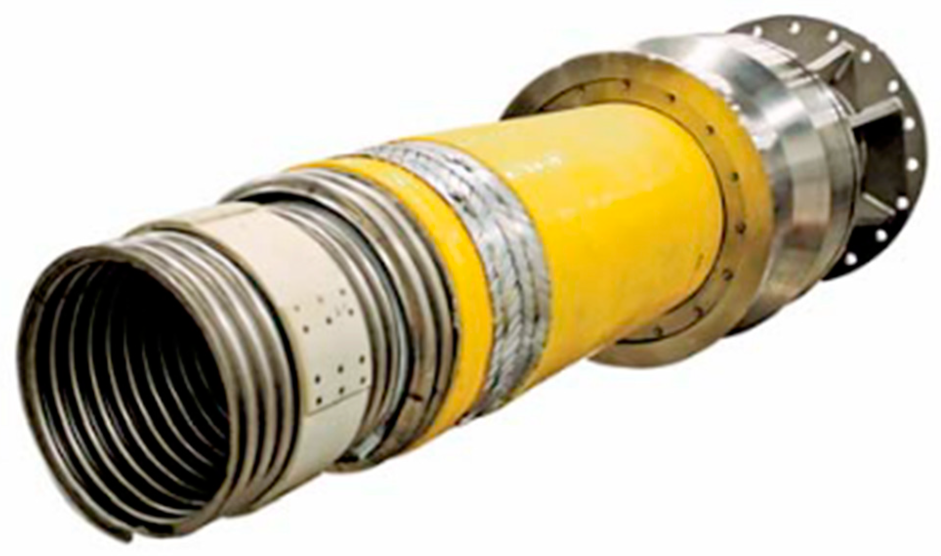
3.1. Reinforced Corrugated Hose

The structure of the reinforced corrugated hose mainly consists of an inner corrugated metal pipe, an armor layer, a helical supporting layer, an insulation layer, and a leakproof layer [15]. The inner corrugated metal pipe is located in the innermost layer of the hose structure and serves to resist internal radial pressure, preventing leakage of cryogenic liquid during operation. The armoring layer primarily bears the axial load during operation while also providing some insulation capability. The helical supporting layer, typically located outside the armoring layer, ensures the correct positioning of the armoring layer and provides some radial support. At least one insulation layer is required in the hose structure to prevent ice formation on the outside of the hose and to maintain a stable internal temperature. The leakproof layer prevents the ingress of external seawater and the leakage of internal cryogenic liquid, and it also has leak monitoring capabilities. This type of hose has a high bending stiffness, with a larger minimum bending radius, offering excellent sealing and structural strength. The structure of the reinforced corrugated hose is shown in Figure 2.
Depending on the operating conditions, the reinforced corrugated hose can be divided into two types: suspended and floating hoses. Suspended hoses are primarily used for side-by-side transfer and are generally suitable for nearshore conditions with relatively small distances between vessels, as shown in Figure 3a. Floating hoses are mainly used for tandem transfer, allowing operation in more severe conditions with larger distances between vessels [12,16], as shown in Figure 3b. These two types of hoses, developed by Technip [17], consist of an inner corrugated pipe, a tensile armor layer, an insulation layer, and an external protective layer, as shown in Figure 4. The main difference between the two is that the suspended hose has a smaller minimum bending radius, allowing for greater bending during side-by-side transfer. The floating hose has a lower overall density, better insulation, and is capable of floating during long-distance tandem transfers, as well as preventing LNG vaporization.

3.2. Vacuum-Insulated Corrugated Hose

The structure of the vacuum-insulated corrugated hose mainly consists of two separate layers of metal corrugated pipes (inner and outer), a tensile armor layer, a vacuum insulation layer, and an outer protective sleeve [15]. The working principle of the hose is to use gaskets to support the inner and outer metal corrugated pipes to form an annular gap and then use a vacuum pump to evacuate the air from the gap, creating a vacuum layer to achieve thermal insulation. Pressure and temperature sensors are installed in the annular gap to monitor pressure and temperature changes, serving to detect any leakage in the structure. The structure of the vacuum-insulated corrugated hose is shown in Figure 5. A representative of this type of hose is the LNG vacuum-insulated corrugated hose developed by Nexans [18]. However, due to the use of double corrugated pipes, this hose has relatively lower bending performance and is suitable for tandem transfer in relatively favorable sea conditions, as shown in Figure 6.

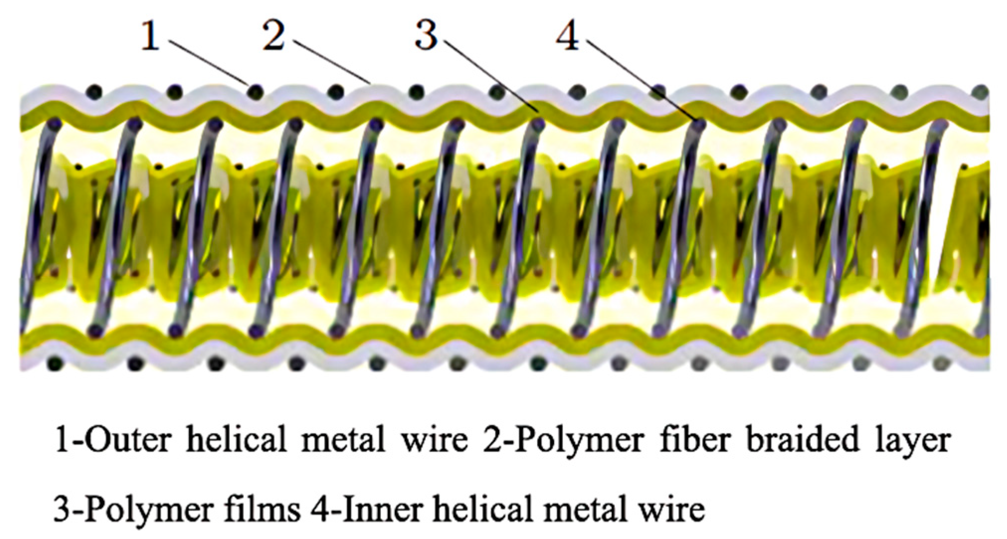
3.3. Composite Cryogenic Hose

The composite cryogenic hose differs from the two aforementioned types of cryogenic hoses, as it features multiple layers of polymer films and a polymer fiber braided material, which are wound and fixed in place by a double-spring structure formed by inner and outer helical metal wires, creating a sealed tubular structure [15]. The polymer film layer effectively prevents leakage of cryogenic liquid during the transmission process, while the polymer braided layer provides radial and axial strength to the hose. The double-spring metal wire structure on the inside and outside enhances the strength against internal pressure, while allowing great flexibility. The structure of the composite cryogenic hose is shown in Figure 7.
The cryogenic composite hose, developed by Dunlop for LNG transmission, is a representative example [19], as shown in Figure 8. In addition to the polymer films and fabric layers, it includes an extra thin thermal insulation layer. It offers excellent flexibility and a small minimum bending radius, making it well-suited for withstanding the relative motion between vessels in harsh sea conditions. Despite the thermal insulation layer, the composite hose family, in general, is not designed for long-distance transmission as in the case of tandem transfer, given the poor thermal insulation capability.
To provide better insulation for composite hoses, Trelleborg and Total developed a composite cryogenic hose called Cryoline (see Figure 9) for LNG transfer, which features a “pipe-in-pipe” structure [21,22]. The inner layer of the hose uses a double-spring design, while the outer layer is wrapped with a thick insulation layer comparable to that used by reinforced corrugated hoses and an outer protection layer. This design effectively enhances thermal insulation, while preserving the flexible character of the composite cryogenic hose. In addition, the insulation layer is embedded with a leak detection system, improving the safety of the hose during transportation.

3.4. Comparison of Existing Hose Designs

Table 1 presents a comparison of the key mechanical and thermal insulation characteristics of the aforementioned hoses. Reinforced corrugated hoses offer high tensile strength and pressure resistance due to their robust metallic construction, but their bending stiffness is also high, resulting in a larger minimum bending radius. Vacuum-insulated hoses provide the best thermal insulation by creating a high-efficiency vacuum barrier, minimizing heat ingress and vaporization risk. Their tensile strength is slightly lower than that of reinforced corrugated hoses but remains sufficient for most offshore transfer operations. However, their double-layered metallic design reduces flexibility and increases weight, which can complicate installation and limit adaptability in offshore operations. Composite hoses, on the other hand, typically have lower mechanical strength but offer excellent flexibility and reduced weight, making them easier to handle in marine environments. Their insulation performance is limited due to the absence of a dedicated thermal insulation layer; however, advanced designs, such as Cryoline, have significantly enhanced their thermal properties, although their strength is still inferior to that of metal-based designs. These comparisons provide a technical foundation for selecting hose types under different design priorities in LCO2 ship-to-ship transfer systems.

4. Main Findings

4.1. Characteristics of LCO2 and Implications for LCO2 Hose Design

To design a cryogenic hose specialized for LCO2, one has to understand its unique physical and chemical characteristics. In this section, characteristics of LCO2 are summarized and the implications for LCO2 cryogenic hose design are analyzed.

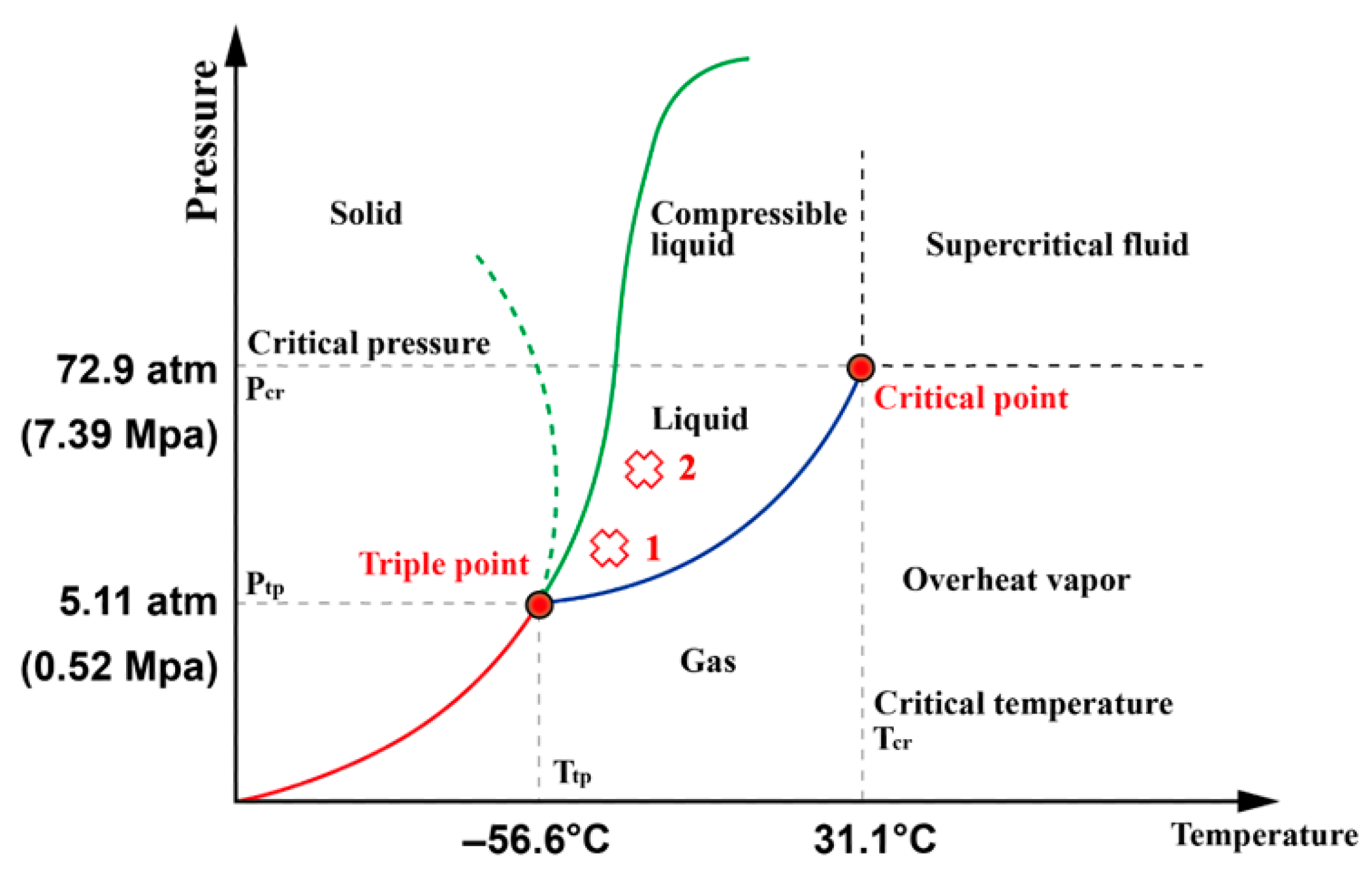
4.1.1. Physical and Chemical Properties

Table 2 compares the physical and chemical properties of LCO2 and other cryogenic liquids frequently transported by cryogenic hoses. Compared to other cryogenic liquids, LCO2 has a higher liquid density and a relatively high boiling point. Although pure LCO2 is not corrosive to metals, it can react with moisture inside the hose to form corrosive carbonic acid. Additionally, gas impurities such as NOx, H2S, and SOx mixed in the captured industrial CO2 can also dissolve in water, forming acidic liquids that exacerbates corrosion [23].

4.1.2. LCO2 Transportation Conditions

During the transportation of LCO2, it is crucial to regulate the temperature and pressure inside the hose to prevent vaporization, which could cause a rise in internal pressure and compromise the hose’s structural integrity. The phase diagram of CO2 is shown in Figure 10. At atmospheric pressure, CO2 exists in a solid state when the temperature is below −78 °C. The triple point occurs at a temperature of −56.6 °C and a pressure of 0.518 MPa, which corresponds to 5.11 atm. The critical temperature is 31.1 °C, with a pressure of 7.39 MPa, equivalent to 72.9 atm. Under atmospheric pressure, CO2 cannot exist in a liquid state; as the temperature increases, it sublimates directly from solid to gas [27].
For the long-distance transportation of CO2 on land, supercritical CO2 is primarily used, with high temperature and pressure conditions. Under this condition, CO2 has a lower viscosity, which is beneficial for long-distance land pipeline transportation [28]. For offshore ship-to-ship transfer using hoses, supercritical pressure can hardly be feasible. As a result, CO2 in liquid state is a more desirable option [29]. The LCO2 transportation conditions in field operations are mainly low temperature and low pressure, or high temperature and medium pressure. Under low-temperature and low-pressure conditions, the temperature is controlled at −53 °C, and the pressure is controlled at 1.5 MPa (point 1 in Figure 10). Under high-temperature and medium-pressure conditions, the temperature is controlled at −35 °C, and the pressure is controlled at 1.9 MPa (point 2 in Figure 10). The liquid phase under high-temperature and medium-pressure conditions has a wider temperature range, and thus more stable than the low-temperature and low-pressure conditions. Overall, the LCO2 cryogenic hose calls for a higher pressure rating than hoses conveying other cryogenic liquids, which poses considerable challenges for structural strength design.

4.1.3. Practical Implications for LCO2 Hose Design

The unique physical and chemical properties of LCO2 impose specific challenges for hose design. The formation of carbonic acid from moisture contamination requires the use of corrosion-resistant materials to ensure long-term durability. Additionally, the relatively high boiling point and liquid density of LCO2 necessitate a hose design capable of withstanding higher internal pressures compared to hoses designed for other cryogenic liquids. To prevent vaporization during transportation, maintaining temperatures below −53 °C at pressures above 1.5 MPa is essential. This necessitates the use of effective thermal insulation layers to minimize heat ingress, as well as materials capable of retaining mechanical integrity at cryogenic temperatures. Furthermore, the higher-pressure ratings required for LCO2 transfer significantly influence the structural strength design of the hose, emphasizing the need for robust reinforcement layers. These practical implications are directly reflected in the performance criteria and material selection process described in the following sections.

4.2. LCO2 Cryogenic Hose Design Methods

Based on the survey of existing cryogenic hoses, a conceptual design of the LCO2 cryogenic hose for offshore tandem ship-to-ship transfer is proposed.

4.2.1. Design Requirements for LCO2 Hoses

In deep-sea environments with harsh sea conditions, tandem ship-to-ship transfer method is the preferred choice for transporting LCO2. Maintaining a high internal pressure (over 1 MPa) is necessary to prevent the LCO2 from vaporizing. However, high internal pressure compromises the flexibility of the hose, making it difficult to meet the required bending radius during storage and installation. Therefore, the design should prioritize flexibility to minimize the bending radius as much as possible. Given the narrow temperature range of liquid LCO2, an insulation layer must be incorporated into the hose to prevent vaporization during long-distance tandem transfer. Additionally, low-density insulation materials can provide buoyancy, allowing the hose to float on the water.
To assess the suitability of different hose types for LCO2 applications, Table 3 summarizes key performance indicators related to LCO2 adaptability, including anti-corrosion capability (important due to CO2’s tendency to form carbonic acid in the presence of water), thermal protection (needed to minimize phase change), floating ability, and flexibility.
As shown in Table 3, while metal-based hoses offer excellent pressure resistance and thermal insulation, they suffer from poor corrosion resistance when exposed to LCO2 and are relatively rigid. Standard composite hoses provide better corrosion resistance and flexibility but lack the insulation and pressure tolerance required for LCO2 transport. The Cryoline-type composite hose achieves a balanced performance, offering improved thermal protection and anti-corrosion capability while maintaining adequate pressure tolerance and flexibility. Based on these evaluations, the Cryoline composite hose design is recommended for LCO2 transportation.

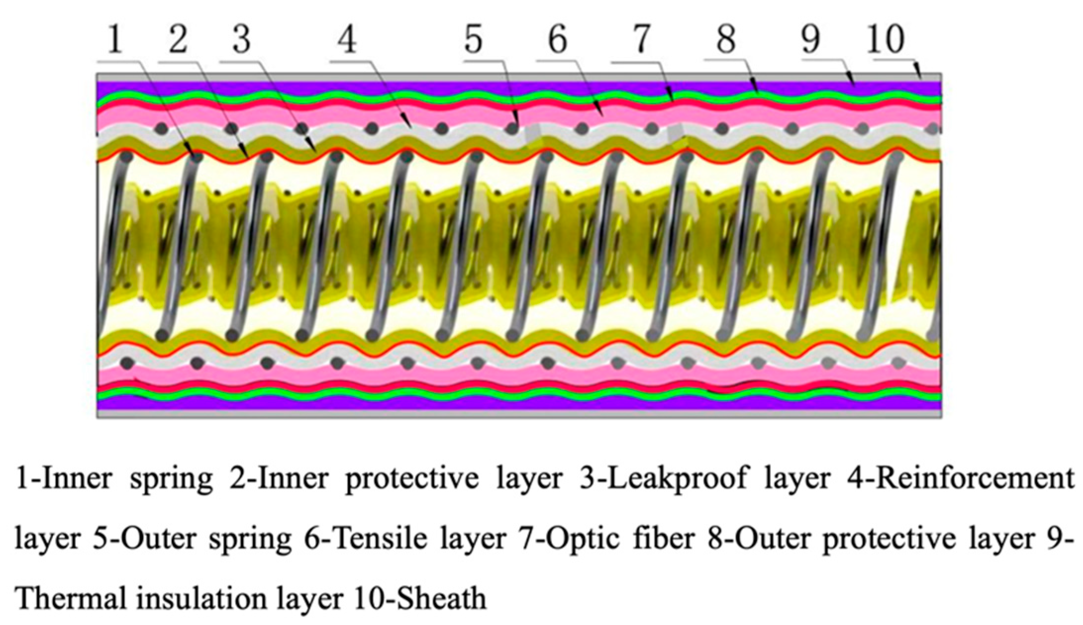
4.2.2. Conceptual LCO2 Cryogenic Hose Design

This section outlines a more detailed design approach for the LCO2 hose, providing practical references for its engineering applications. The conceptual hose structure is shown in Figure 11. The inner layer of the hose can adopt a double-spring structure to secure multiple layers of non-bonded composite functional materials. These functional layers primarily include an inner protective fabric, a leakproof layer, and a reinforcement layer. The inner protective fabric helps to reduce the impact of the LCO2 fluid on the leakproof layer, which is created by winding multiple layers of polymer sealing materials. The reinforcement layer is designed to primarily withstand axial tensile loads and bear internal pressure. A tensile layer wrapped around the outer spring is designed to resist the longitudinal tensile forces caused by the weight of the cryogenic liquid during long-distance transportation. In addition, optical fibers are wound around the tensile layer to monitor the hose’s operational status in real time, with a protective layer around the optical fibers to prevent function failure due to friction and wear within the hose. A certain thickness of insulation material can be placed on the outer layer of the hose to form the insulation layer. The outermost layer of the hose is the sheath, which ensures that the hose structure is isolated from the external seawater environment. This prevents seawater infiltration, which could cause corrosion or cracking, leading to functional failure. It also protects the hose structure from physical damage caused by external factors during transportation and operation.
In addition to the structural design considerations discussed above, the key functional requirements for the conceptual LCO2 hose are summarized in Table 4. While standards dedicated to LCO2 cryogenic hose is absent, these requirements are established based on applicable standards for cryogenic hose design, including the BS EN 1474-2 standard for LNG hoses [15], BS EN 13766 standard for thermoplastic multi-layer hoses [30], ISO 21012 standard for cryogenic hoses [31], and further refined through the analysis conducted in this research. The requirements include a maximum allowable working pressure of 3.5 MPa and a minimum burst pressure of 17.5 MPa, which is equivalent to five times the maximum allowable pressure. Flexibility is also critical to the hose design, with a target minimum bending radius of ten times the hose diameter to ensure adequate maneuverability during handling and operation. Corrosion resistance is essential, as the hose must prevent failure over its intended service life when exposed to LCO2, particularly in the presence of moisture. Additionally, thermal ingress should be maintained below 60 W/m to prevent vaporization, with a minimum operational temperature of −53 °C to accommodate the cryogenic nature of LCO2. Finally, the hose must support a maximum flow rate of 4000 m3/h to meet practical transfer requirements during offshore tandem ship-to-ship operations. The specifications provided in Table 4 serve as essential criteria to guide the material selection and structural design of the hose, ensuring its suitability for LCO2 transfer applications.

4.2.3. Hose Material Selection

The selection of materials for the different functional layers of the LCO2 cryogenic hose must take into account various factors, including the mechanical properties, corrosion resistance, leakproof performance, thermal insulation properties, and compatibility with the cryogenic fluid inside. Based on the conceptual hose design in Section 4.1, the potential materials and functions for hose layers are summarized in Table 5.
The selection of insulation materials for the cryogenic composite hose directly impacts the overall insulation performance of the LCO2 hose, and the thermal insulation layer is a key difference between the conceptual cryogenic hose design from the traditional composite cryogenic hose. It is therefore necessary to further analyze the selection of insulation materials. A summary of the material properties and insulation performance of the insulation materials is provided in Table 6.
As shown in Table 6, among various insulation materials, aerogel has the lowest thermal conductivity and density, offering a wider range of operating temperatures. It is the optimal choice for the insulation layer of cryogenic composite hoses. Its excellent thermal insulation performance and lightweight properties ensure the stability of the internal temperature while reducing the overall weight of the hose, allowing better floating ability. However, the use of aerogel in cryogenic composite hoses is currently limited, and further research and development are needed to expand its application.

4.2.4. Anti-Corrosion Measures

Based on the physical and chemical properties of LCO2 and the causes of corrosion outlined in Section 3, it is necessary to implement corrosion protection measures to avoid hose corrosion. Current research on corrosion during the CO2 storage and transportation process primarily focuses on the supercritical state and land-based transportation, typically requiring pipeline corrosion protection [26,36]. Research specifically on the corrosion of LCO2 is relatively limited. Given that factors such as temperature, pressure conditions, and impurity content can all influence the corrosion rate, and the complex reaction mechanisms between these factors make quantitative analysis difficult [37]. The following preliminary corrosion protection measures for LCO2 cryogenic hoses are proposed:
1. Material Selection: The material for the inner spring metal wire should be stainless steel containing a certain proportion of chromium (as recommended in Table 5), which has excellent corrosion resistance.
2. Apply Coatings: A coating layer can be applied to the surface of the inner spring metal wire to isolate LCO2 from the metal material, thereby achieving corrosion protection. However, the thermal expansion coefficient of the corrosion-resistant coating may differ significantly from that of the spring metal wire, which could cause the coating to detach during LCO2 transmission. In that case, severe pitting corrosion may happen at the exposed area. As a result, it is critical to select coating materials with similar thermal expansion ratio with the spring metal wire.
3. Injecting Corrosion Inhibitors: Injecting corrosion inhibitors during LCO2 transportation can effectively slow down the corrosion rate [36].
In addition to the methods above, it is important to minimize the generation of water vapor and other sulfur- and nitrogen-containing impurities at the source during industrial CO2 capture [38]. When selecting corrosion protection measures, their economic feasibility should also be considered to balance corrosion protection effectiveness and cost.

4.2.5. Integration of Leak Detection System

During the transmission operation of the LCO2 cryogenic hose, monitoring leakage in the pipeline is crucial for ensuring the hose’s integrity. Real-time monitoring of areas prone to leakage and fatigue damage is beneficial for early warning of structural leaks. Fiber optic sensors have become one of the most widely used sensors in the field of structural monitoring in recent years, offering advantages such as strong anti-interference capabilities, high precision, and high sensitivity. These sensors are currently applied in the online monitoring of land-based natural gas pipeline [39] and flexible risers [40]. The advantage of fiber optic sensors lies in their ability to precisely capture minute structural deformations and temperature changes. When LCO2 leakage occurs in the hose during service, the fiber optic sensors arranged at specific positions between the hose layers can accurately detect localized structural deformations caused by pressure drops and sudden rises or falls in temperature. Real-time monitoring methods for such data can effectively identify whether leakage has occurred in the hose structure.
However, challenges remain in applying fiber optic sensing for leakage monitoring in flexible hoses, which undergo significant motion during operation, causing great friction between the sensor and adjacent structural layers [41]. NKT has incorporated fiber optic sensor technology for temperature, strain, and leakage monitoring in composite hoses [42]. The flat steel embedded with fiber optics is wound as a tensile armor layer inside the hose. The two components are arranged in such a way that they can slide relative to each other, helping to prevent damage to the fiber optics. However, the sliding between the steel and fiber optics can still abrase the sensor over time. Further research and optimized solutions are required to enhance the reliability of fiber optic deployment, enabling real-time monitoring of LCO2 cryogenic hoses during ship-to-ship transfer.

4.3. Mechanical Analysis of the LCO2 Cryogenic Hose

This section addresses the mechanical analysis of LCO2 cryogenic hoses and associated methods, serving as the scientific basis for safety assessments and parameter optimization. Due to the high pressure required to maintain CO2 in its liquid state (Section 3.2), rigorous strength verification is essential. Building on studies of other cryogenic hoses used offshore, performance under various operational loads—including tensile forces [43,44], internal pressure [45], bending [46], torsion, and temperature loads [47,48]—must be evaluated to locate stress concentrations. Because the hose is a multi-layer composite, creating a universal theoretical model is difficult, so finite element methods (FEM) are commonly employed [48,49]. For the composite reinforcement layer, one approach is to treat it as a homogeneous material, using mechanical properties derived from micro-unit FEM simulations [50]. Alternatively, a mechanical response model can be established based on anisotropic laminated composite theory [51]. It is also crucial to consider local instability of structural layers under internal pressure, bending, and torsion [48,52]. For example, bending can cause cross-sectional ovalization and local instability, leading to stress concentrations and reduced overall stability. Accurate simulation and analysis of these complex load conditions remain key to informing practical design decisions, such as optimizing the layering and material selection for enhanced stability under service loads, while reducing overall failure risk in actual operating conditions.
The flow and heat transfer characteristics of LCO2 inside the hose significantly influence transportation efficiency and safety. However, because the double-spring structure creates an irregular inner surface, direct theoretical formulas for friction coefficients are unavailable. Three-dimensional Computational Fluid Dynamics (CFDs), employing RANS [53,54] or LES [55,56], can accurately simulate flow friction resistance for low-temperature fluids. Since the temperature and pressure window for liquid CO2 is narrow, operating fluctuations can trigger gas–liquid or liquid–solid flow inside the hose, impairing transportation efficiency and risking blockages [57,58]. Consequently, detailed analysis of heat transfer and multiphase flow behavior is necessary. Multiphase flow models such as Volume of Fluid (VOF) [59,60] and Mixture models [61], or the Eulerian–Eulerian model [62], can be used for more detailed simulations. CFD and multiphase flow analyses help identify conditions under which phase change or excessive friction losses occur, guiding design modifications (e.g., improved insulation or internal surface treatments) to maintain efficient liquid CO2 transportation. Such analyses thus directly inform operational guidelines and reduce the likelihood of flow-related failure.
In actual cryogenic hose transportation, multi-field coupling effects, including heat, fluid, and structural interactions, are often involved. The coupling between unstable internal flow, external flow, and the hose structure may lead to hose vibrations [63], creating localized stresses that leads to fatigue. Unlike risers, where vortex-induced vibrations caused by ocean currents are the main dynamic response, the dynamic behavior of floating hoses is more influenced by waves [64]. Increased internal flow velocity and pressure reduce the natural frequency of the hose, and when the natural frequency approaches zero, the hose becomes unstable [65]. Due to the long slenderness ratio, the dynamic analysis of hoses can often be simplified to a one-dimensional beam structure, with dynamic response described using Euler–Bernoulli beam theory [66,67]. For hoses with linear shapes expressible by explicit formulas, the Generalized Integral Transform Technique (GITT) can be used for theoretical solutions [68,69]. For irregular hose shapes that cannot be expressed by explicit formulas, finite element methods can be employed to solve the established beam dynamic model [65]. Moreover, the cryogenic fluid inside the hose also causes non-uniform temperature distribution in the hose structure due to convective heat transfer, which results in thermal stresses from local temperature gradients and boundary constraints [70,71]. For pipelines transporting super low-temperature liquids, such as liquid nitrogen or LNG, the maximum thermal stress often occurs during the pre-cooling stage, when the instantaneous temperature gradient is at its peak [72]. In the case of higher temperature LCO2 pipelines, the maximum thermal stress is more likely to occur during transportation due to accumulated thermal expansion, coupled with boundary constraints. Thermal stress analysis of cryogenic hoses requires the use of coupled numerical methods for heat, flow, and solid mechanics, integrating Computational Fluid Dynamics models with Computational Solid Mechanics models [70,73]. In practice, these coupled analyses are most valuable for pinpointing zones of high thermal stress and for determining the dynamic responses that could lead to fatigue under real operating conditions. As a result, the primary design adjustments, such as reinforcing critical layers or altering boundary constraints, can be concentrated where simulation outcomes reveal the highest stress or the greatest risk of instability, ensuring a safer and more durable hose configuration.

4.4. Discussion

This article discussed the physical and chemical characteristics of LCO2 and proposed practical implications for LCO2 hose design for offshore tandem ship-to-ship transfer. A conceptual composite cryogenic hose configuration that balances flexibility, strength, and thermal insulation were proposed. In this section, the challenges associated with subsequent design stages and operational conditions are further discussed.
The design and operation of LCO2 hoses for offshore tandem ship-to-ship transfer present significant challenges due to the demanding conditions under which these hoses must operate. One of the most critical design challenges is ensuring sufficient structural strength to withstand high internal pressures. The proposed LCO2 hose structure incorporates a double-spring-supported main structure designed to provide both flexibility and strength. However, maintaining adequate structural integrity under a maximum allowable working pressure of 3.5 MPa and a burst pressure of 17.5 MPa poses considerable difficulties. Achieving these pressure ratings requires a robust reinforcement layer with sufficient thickness and mechanical strength to prevent structural failure during operation. The reinforcement layer must be carefully designed to provide adequate tensile strength, compressive resistance, and internal pressure resistance. However, increasing the thickness of the reinforcement layer to enhance structural strength can also adversely impact flexibility, which is a critical requirement for offshore floating hoses. Striking a balance between strength and flexibility remains a significant design challenge.
Additionally, the high-pressure conditions inherent in LCO2 transfer operations increase the risk of failure at hose fittings and connections, which represent weak points in the overall hose assembly. The fittings must be designed and tested to withstand both the maximum allowable working pressure and the burst pressure to prevent catastrophic failure. Improperly designed or inadequately tested fittings can result in leakage, structural failure, or even complete separation of the hose from the fittings. This challenge is exacerbated by the fact that hose fittings are subject to both static and dynamic loading conditions during operation, including bending, torsion, and axial tension. Therefore, the mechanical performance of fittings must be thoroughly validated through both experimental testing and computational simulations to ensure reliability and safety.
Another major design challenge involves maintaining effective thermal insulation to prevent LCO2 from vaporizing or solidifying during transportation. As highlighted in Section 4.3, the phase diagram of CO2 demonstrates that small deviations in temperature or pressure can lead to phase changes, resulting in vaporization or solidification. The proposed LCO2 hose design includes a thermal insulation layer intended to minimize heat ingress and maintain a stable internal temperature. However, ensuring adequate thermal insulation over long distances, especially during tandem ship-to-ship transfer operations, is complex. Even minor heat ingress can cause localized vaporization, resulting in pressure spikes that compromise hose integrity. Additionally, if the temperature drops below the triple point of CO2, solidification can occur, leading to blockages and potential damage to the hose structure. The challenge of maintaining proper thermal insulation is further compounded by the need for the hose to remain flexible and lightweight, making the selection of appropriate insulation materials and configurations particularly important.
Furthermore, the dynamic loading conditions experienced by floating LCO2 hoses during offshore operations present a unique set of challenges that must be addressed during the design phase. As highlighted in Section 4.3, floating hoses are subjected to various external forces, including wave-induced motions, vessel movements, and environmental factors such as wind and currents. The internal flow of LCO2 also contributes to dynamic loading, particularly when flow rates fluctuate or when pressure transients occur. These dynamic forces can cause the hose to experience cyclic bending, tension, compression, and torsion, which can ultimately result in fatigue failure if not properly accounted for. Given the flexible nature of the hose, significant dynamic responses may occur over the course of its service life. Therefore, fatigue life verification is essential during the design phase to ensure that the hose can withstand the repeated loading cycles encountered during operation.

5. Conclusions

The technology of cryogenic hoses for offshore LCO2 ship-to-ship transfer is a critical component in the efficient implementation of Carbon Capture, Utilization, and Storage (CCUS) in marine environments. Due to the narrow liquid phase range of LCO2, temperature and pressure control is more stringent compared to cryogenic hoses for other cryogenic liquids, and the corrosion risk is greater. This imposes higher demands on material selection, structural design, and corrosion protection. Based on a survey of existing cryogenic hose designs, this paper described a conceptual composite cryogenic hose design consisted of a double-spring supported internal composite hose, a thermal insulation layer, an outer sheath, and other functional layers to ensure structural strength and sealing. The proposed hose structure aims to achieve a balance between flexibility and internal pressure resistance, enabling it to withstand high-pressure conditions while maintaining sufficient flexibility for dynamic offshore environments. Additionally, the enhanced thermal insulation performance supports efficient heat retention, allowing for reliable long-distance tandem ship-to-ship transfer of LCO2. Mechanical analyses on the hose structure, internal and external fluid, heat transfer, and their coupling effects were proposed to evaluate safety and reliability of the LCO2 cryogenic hose.
Nevertheless, this study has certain limitations, including the lack of optimized material selection and functional layer configuration. Furthermore, the current analysis primarily considers each functional requirement, such as flexibility, strength, corrosion resistance, and thermal insulation, independently, without adopting an integrated design approach that balances these factors. Additionally, the proposed hose design has not undergone experimental validation under diverse operational conditions.
Future research should attempt to enhance the practical applicability of LCO2 cryogenic hoses. One critical direction is to optimize material selection and functional layer configuration to achieve a balance between flexibility, strength, corrosion resistance, and thermal insulation. Further experimental investigations on the corrosion behavior of LCO2 hoses under varying operational conditions, particularly when exposed to impurities, such as water, SOx, and NOx, will be essential for developing more robust anti-corrosion measures. Another important future work direction involves integrating real-time monitoring systems, such as fiber optic sensors, within the hose structure. Such monitoring systems can provide early warnings of leakage, structural degradation, or operational anomalies, thereby enhancing the reliability and safety of LCO2 transfer operations. Finally, standardization efforts for LCO2 cryogenic hoses should be advanced to establish comprehensive performance criteria covering pressure rating, flexibility, corrosion resistance, thermal insulation, and leak detection. Collaboration with industry stakeholders and regulatory bodies will be crucial in developing guidelines that ensure the safe and effective deployment of LCO2 cryogenic hoses for offshore CCUS applications.
Overall, this study provides a foundational reference for the development of floating LCO2 cryogenic hoses for tandem ship-to-ship transfer, supporting marine carbon sequestration and the engineering advancement of CCUS technology.

Author Contributions

H.C.: writing—original draft, supervision, funding acquisition. F.L.: review and editing. Y.B.: investigation. Y.Y.: investigation. H.L.: review. H.M. and X.Z.: analysis. Z.L.: writing—original draft, review and editing. J.Y.: funding acquisition, resources, supervision. All authors have read and agreed to the published version of the manuscript.

Funding

This research was financially supported by the National Natural Science Foundation of China (No. 52201312), the National Key R&D Program of China (No. 2021YFC2801602), the Natural Science Foundation of Zhejiang, China (No. LQN25E090004), and the Natural Science Foundation of Liaoning, China (2023-BSBA-052). This support is gratefully acknowledged.

Data Availability Statement

No new data were created or analyzed in this study. Data sharing is not applicable to this article.

Conflicts of Interest

Author Hao Chen and Fangqiu Li were employed by the CNOOC Gas & Power Group Co., Ltd. The remaining authors declare that the research was conducted in the absence of any commercial or financial relationships that could be construed as a potential conflict of interest.

References

  1. Ren, Q.; Wei, S.; Du, J.; Wu, P. Research Progress and Perspectives on Carbon Capture, Utilization, and Storage (CCUS) Technologies in China and the USA: A Bibliometric Analysis. Environ. Sci. Pollut. Res. 2023, 30, 76437–76454. [Google Scholar] [CrossRef] [PubMed]
  2. De Pryck, K.; Boettcher, M. The Rise, Fall and Rebirth of Ocean Carbon Sequestration as a Climate “Solution”. Glob. Environ. Change 2024, 85, 102820. [Google Scholar] [CrossRef]
  3. Jung, J.Y.; Huh, C.; Kang, S.G.; Seo, Y.; Chang, D. CO2 Transport Strategy and Its Cost Estimation for the Offshore CCS in Korea. Appl. Energy 2013, 111, 1054–1060. [Google Scholar] [CrossRef]
  4. The Maritime Executive 55 Vessels Required by 2030 for Emerging CO2 Transport and Storage. Available online: https://maritime-executive.com/article/55-vessels-required-by-2030-for-emerging-co2-transport-and-storage (accessed on 17 February 2025).
  5. Equinor The Northern Lights Project. Available online: https://www.equinor.com/energy/northern-lights (accessed on 15 February 2025).
  6. INEOS PROJECT GREENSAND. Available online: https://www.ineos.com/inch-magazine/articles/issue-25/project-greensand/ (accessed on 10 February 2025).
  7. Greensand Greensand Paving the Way for Mitigating Climate Change with CCS. Available online: https://www.projectgreensand.com/en/first-carbon-storage (accessed on 10 February 2025).
  8. Perenco the Poseidon Project. Available online: https://perenco-ccs.com/the-poseidon-project/ (accessed on 10 February 2025).
  9. Technip Energies. Technip Energies, DeepC Store and Mitsui O.S.K. Lines Join Forces for a Floating Carbon Capture & Storage Hub Development. Available online: https://www.ten.com/en/media/news/technip-energies-deepc-store-and-mitsui-osk-lines-join-forces-floating-carbon-capture (accessed on 15 February 2025).
  10. DNV CO2 Offshore Injection. Available online: https://www.dnv.com/article/co2-offshore-injection-joint-industry-project/ (accessed on 10 February 2025).
  11. Vopak. Knowledge Sharing Report—CO2 Liquid Logistics Shipping Concept Business Model. 2011. Available online: https://www.globalccsinstitute.com/archive/hub/publications/19011/co2-liquid-logistics-shipping-concept-llsc-overall-supply-chain-optimization.pdf (accessed on 10 February 2025).
  12. Yokozawa, H.; Ito, A. Application for Estimating Motion Behaviors of FPSO/FSRU and Shuttle Tanker in alongside and Tandem Mooring Conditions. In Proceedings of the International Conference on Offshore Mechanics and Arctic Engineering—OMAE, Halkidiki, Greece, 12–16 June 2005; Volume 1A. [Google Scholar]
  13. Engel, F.; Kather, A. Improvements on the Liquefaction of a Pipeline CO2 Stream for Ship Transport. Int. J. Greenh. Gas Control 2018, 72, 214–221. [Google Scholar] [CrossRef]
  14. Continental. Leading the Charge in Renewable Energy—Marine Hoses and Transfer Systems for LCO2 and Ammonia. Available online: https://www.continental-industry.com/getmedia/d5d73c27-bf2d-4c18-a5d6-b1067fabe1fe/CT-Marine-Hoses-Transfer-Systems-Carbon-Ammonia.pdf (accessed on 11 February 2025).
  15. EN1474-2; British Standard European Norm (BSEN). Installation and Equipment for Liquefied Natural Gas—Design and Testing of Marine Transfer Systems Part 2: Design and Testing of Transfer Hoses. British Standards Institution: London, UK, 2020.
  16. Ferreira, A.L.F.; Morooka, C.K. Evaluation of Response of a Floating Cryogenic Hose in Offloading Operation Between Flng Unit and Lng Carrier in Tandem. In Proceedings of the International Conference on Offshore Mechanics and Arctic Engineering—OMAE, St. John’s, NL, Canada, 31 May–5 June 2015; Volume 5A, pp. 1–10. [Google Scholar]
  17. Abbasi, T.; Hults, J.E.; Mesnage, O.; Simoes, V.; Gerez, J.; Hardiman, R.; Vlekken, J.; Roosbroeck, J. LNG Flexible Integrated with Fiber Optic Distributed Leak System Enhancing Safety, Integrity Monitoring and Life Assessments. In Proceedings of the Offshore Technology Conference Asia, Kuala Lumpur, Malaysia, 22–25 March 2016; OTCA: Brasília, Brazil, 2016. [Google Scholar]
  18. Eide, J.; Haakonsen, R.; Oya, T.V.; Frohne, C. Offshore Tandem Loading of LNG—From Idea to System Approval. In Proceedings of the Annual Offshore Technology Conference, Houston, TX, USA, 5–8 May 2014; Volume 3. [Google Scholar]
  19. Humphreys, V.; Jones, N. Offshore LNG Transfer, a Practical System Based on Proven Oil Transfer Principles. In Proceedings of the Annual Offshore Technology Conference, Houston, TX, USA, 3–6 May 2004; Volume 1. [Google Scholar]
  20. Chen, Q.; Sun, Q.; Yan, J.; Cui, Y.; Yang, L.; Yang, X.; Wu, Z. Development and Recent Progress of Hoses for Cryogenic Liquid Transportation. Polymers 2024, 16, 905. [Google Scholar] [CrossRef]
  21. Lagarrigue, V.; Hermary, J.; Mauries, B. Qualification of a Cryogenic Floating Flexible Hose Enabling Safe and Reliable Offshore LNG Transfer for Tandem FLNG Offloading Systems. In Proceedings of the Annual Offshore Technology Conference, Houston, TX, USA, 5–8 May 2014; Volume 5. [Google Scholar]
  22. Lagarrigue, V.; Herniary, J. Re-Shaping LNG Transfer. In Proceedings of the Annual Offshore Technology Conference, Houston, TX, USA, 30 April–3 May 2018; Volume 1. [Google Scholar]
  23. Suzuki, T.; Toriumi, M.; Sakemi, T.; Masui, N.; Yano, S.; Fujita, H.; Furukawa, H. Conceptual Design of CO2 Transportation System for CCS. Energy Procedia 2013, 37, 2986–2996. [Google Scholar] [CrossRef]
  24. National Institute of Standards and Technology Cryogenics Material Properties. Available online: https://trc.nist.gov/cryogenics/materials/materialproperties.htm (accessed on 12 February 2025).
  25. The Engineering ToolBox The Engineering ToolBox. Available online: https://www.engineeringtoolbox.com/ (accessed on 12 February 2025).
  26. Zhao, C.; Wang, J.; Li, X.; Huang, J.; Chen, H.; Bi, J.; Liu, S.; Lu, G.; Song, K.; Guo, S. Progress in Corrosion Protection Research for Supercritical CO2 Transportation Pipelines. Coatings 2024, 14, 1378. [Google Scholar] [CrossRef]
  27. The Engineering ToolBox Carbon Dioxide—Liquid Properties. Available online: https://www.engineeringtoolbox.com/carbon-dioxide-d_1000.html (accessed on 15 February 2025).
  28. Kim, T.W.; Yoon, H.C.; Lee, J.Y. Review on Carbon Capture and Storage (CCS) from Source to Sink; Part 1: Essential Aspects for CO2 Pipeline Transportation. Int. J. Greenh. Gas Control 2024, 137, 104208. [Google Scholar] [CrossRef]
  29. Roussanaly, S.; Deng, H.; Skaugen, G.; Gundersen, T. At What Pressure Shall CO2 Be Transported by Ship? An In-Depth Cost Comparison of 7 and 15 Barg Shipping. Energies 2021, 14, 5635. [Google Scholar] [CrossRef]
  30. EN13766; British Standard European Norm (BSEN). Thermoplastic Multi-Layer (Non-Vulcanized) Hoses and Hose Assemblies for the Transfer of Liquid Petroleum Gas and Liquified Natural Gas—Specification. British Standards Institution: London, UK, 2010.
  31. ISO 21012:2018; Cryogenic Vessels-Hoses. ISO: Geneva, Switzerland, 2018.
  32. Li, C.; Chen, Z.; Dong, W.; Lin, L.; Zhu, X.; Liu, Q.; Zhang, Y.; Zhai, N.; Zhou, Z.; Wang, Y.; et al. A Review of Silicon-Based Aerogel Thermal Insulation Materials: Performance Optimization through Composition and Microstructure. J. Non-Cryst. Solids 2021, 553, 120517. [Google Scholar] [CrossRef]
  33. Zhang, H.; Fang, W.Z.; Li, Y.M.; Tao, W.Q. Experimental Study of the Thermal Conductivity of Polyurethane Foams. Appl. Therm. Eng. 2017, 115, 528–538. [Google Scholar] [CrossRef]
  34. Schulte, M.; Lewandowski, I.; Pude, R.; Wagner, M. Comparative Life Cycle Assessment of Bio-Based Insulation Materials: Environmental and Economic Performances. GCB Bioenergy 2021, 13, 979–998. [Google Scholar] [CrossRef]
  35. Yu, W.; Lu, W.; Han, X.; Cai, H. Aluminum Silicate Fibers Reinforced Wood-Plastic Composites: A Strengthening Strategy Based on the Interfacial Interactions between Inorganic Fibers and Organic Agricultural Wastes. Bioresources 2021, 16, 3678. [Google Scholar] [CrossRef]
  36. Xiang, Y.; Yuan, Y.; Zhou, P.; Liu, G.; Lyu, W.; Li, M.; Zhang, C.; Zhou, Q.; Zhao, X.; Yan, W. Metal Corrosion in Carbon Capture, Utilization, and Storage: Progress and Challenges. Chin. J. Eng. Sci. 2023, 25, 197–208. [Google Scholar] [CrossRef]
  37. Oosterkamp, A.; Ramsen, J. State-of-the-Art Overview of CO2 Pipeline Transport with Relevance to Offshore Pipelines. Report to the Research Council of Norway. Report Number POL-O-2007-138-A. 2008. Available online: https://www.researchgate.net/profile/Antonie-Oosterkamp/publication/228688545_State-of-the-Art_Overview_of_CO_2_Pipeline_Transport_with_Relevance_to_Offshore_Pipelines/links/0deec5270ceae8bb47000000/State-of-the-Art-Overview-of-CO-2-Pipeline-Transport-with-Relevance-to-Offshore-Pipelines.pdf (accessed on 10 February 2025).
  38. Raganati, F.; Miccio, F.; Ammendola, P. Adsorption of Carbon Dioxide for Post-Combustion Capture: A Review. Energy Fuels 2021, 35, 12845–12868. [Google Scholar] [CrossRef]
  39. Ashry, I.; Mao, Y.; Wang, B.; Hveding, F.; Bukhamsin, A.; Ng, T.K.; Ooi, B.S. A Review of Distributed Fiber-Optic Sensing in the Oil and Gas Industry. J. Light. Technol. 2022, 40, 1407–1431. [Google Scholar] [CrossRef]
  40. Morikawa, S.R.K.; Braga, A.M.B.; Camerini, C.S.; Kato, C.C.; Llerena, R.A.; Camerini, M.G.; Simões, T.B. New Advances in Flexible Riser Monitoring Techniques Using Optical Fiber Sensors. In Proceedings of the International Conference on Offshore Mechanics and Arctic Engineering—OMAE, Rio de Janeiro, Brazil, 1–6 July 2012; Volume 3. [Google Scholar]
  41. Lally, E.M.; Reaves, M.; Horrell, E.; Klute, S.; Froggatt, M.E. Fiber Optic Shape Sensing for Monitoring of Flexible Structures. In Proceedings of the Sensors and Smart Structures Technologies for Civil, Mechanical, and Aerospace Systems, San Diego, CA, USA, 12–15 March 2012; Volume 8345. [Google Scholar]
  42. Andersen, M. Method of Mounting a Sensor Arrangement in a Tubular Member, and Use of the Method. US Patent 7,024,941, 11 April 2006. [Google Scholar]
  43. Buitrago, J.; Slocum, S.T.; Hudak, S.J.; Long, R. Cryogenic Structural Performance of Corrugated Pipe. In Proceedings of the International Conference on Offshore Mechanics and Arctic Engineering—OMAE, Shanghai, China, 6–11 June 2010; Volume 6, pp. 331–342. [Google Scholar]
  44. Gao, S.; An, C.; Wei, D.; Li, Y.; Estefen, S.F.; Yang, R. Mechanical Structure Behavior of a Double Carcass Floating Hose Under Tensile Load. In Proceedings of the 33rd International Ocean and Polar Engineering Conference, Ottawa, ON, Canada, 18–23 June 2023. ISOPE-I-23-463. [Google Scholar]
  45. Ying, X.; Yan, J.; Zhang, K.; Yang, Z.; Cao, H.; Bu, Y. Study on Competition Mechanism of Deformation Modes of U-Shaped Bellows Under Internal Pressure. Mar. Struct. 2023, 92, 1–18. [Google Scholar] [CrossRef]
  46. Huang, G.; Wu, W. Armored Steel Wire Stress Monitoring Strategy of a Flexible Hose in LNG Tandem Offloading Operation. Ocean Eng. 2023, 281, 114775. [Google Scholar] [CrossRef]
  47. Hu, H.; Yan, J.; Zhou, B.; Yang, Z.; Yang, L.; Fan, J. Thermal and Mechanical Coupled Analysis of Marine Composite Cryogenic Pipeline. In Proceedings of the International Conference on Offshore Mechanics and Arctic Engineering—OMAE, Glasgow, UK, 9–14 June 2019; Volume 5A. [Google Scholar]
  48. Amaechi, C.V.; Chesterton, C.; Butler, H.O.; Gu, Z.; Odijie, A.C.; Wang, F.; Hou, X.; Ye, J. Finite Element Modelling on the Mechanical Behaviour of Marine Bonded Composite Hose (MBCH) Under Burst and Collapse. J. Mar. Sci. Eng. 2022, 10, 151. [Google Scholar] [CrossRef]
  49. Bardi, F.C.; Tang, H.; Kulkarni, M.; Yin, X. Structural Analysis of Cryogenic Flexible Hose. In Proceedings of the ASME 2011 30th International Conference on Ocean, Offshore and Arctic Engineering, Rotterdam, The Netherlands, 19–24 June 2011; pp. 593–606. [Google Scholar]
  50. Ying, X.; Geng, D.; Cao, H.; Zhang, K.; Bu, Y.; Yang, Z.; Yan, J. Equivalent Mechanical Properties of Spiral Skeleton Composite Flexible Low-Temperature Pipeline Based on NIAH. Zhendong Yu Chongji/J. Vib. Shock 2023, 42, 10–16. [Google Scholar] [CrossRef]
  51. Zhou, Y.; Duan, M.; Ma, J.; Sun, G. Theoretical Analysis of Reinforcement Layers in Bonded Flexible Marine Hose under Internal Pressure. Eng. Struct. 2018, 168, 384–398. [Google Scholar] [CrossRef]
  52. Yan, J.; Ying, X.; Cao, H.; Xiong, F.; Zhang, K.; Yang, Z. Mechanism of Mechanical Analysis on Torsional Buckling of U-Shaped Bellows in FLNG Cryogenic Hoses. J. Mar. Sci. Eng. 2022, 10, 1405. [Google Scholar] [CrossRef]
  53. Pisarenco, M.; van der Linden, B.; Tijsseling, A.; Ory, E.; Dam, J. Friction Factor Estimation for Turbulent Flows in Corrugated Pipes with Rough Walls. J. Offshore Mech. Arct. Eng. 2010, 133, 011101. [Google Scholar] [CrossRef]
  54. Calomino, F.; Alfonsi, G.; Gaudio, R.; D’Ippolito, A.; Lauria, A.; Tafarojnoruz, A.; Artese, S. Experimental and Numerical Study of Free-Surface Flows in a Corrugated Pipe. Water 2018, 10, 638. [Google Scholar] [CrossRef]
  55. Calomino, F.; Tafarojnoruz, A.; De Marchis, M.; Gaudio, R.; Napoli, E. Experimental and Numerical Study on the Flow Field and Friction Factor in a Pressurized Corrugated Pipe. J. Hydraul. Eng. 2015, 141, 04015027. [Google Scholar] [CrossRef]
  56. Jaiman, R.K.; Oakley, O.H.; Adkins, J.D. CFD Modeling of Corrugated Flexible Pipe. In Proceedings of the ASME 2010 29th International Conference on Ocean, Offshore and Arctic Engineering, Shanghai, China, 6–11 June 2010. [Google Scholar]
  57. Munkejord, S.T.; Hammer, M.; Løvseth, S.W. CO2 Transport: Data and Models—A Review. Appl. Energy 2016, 169, 499–523. [Google Scholar] [CrossRef]
  58. Lu, W.; Hu, H.; Qi, G. Effect of Pipe Diameter and Inlet Parameters on Liquid CO2 Flow in Transportation by Pipeline with Large Height Difference. Processes 2019, 7, 756. [Google Scholar] [CrossRef]
  59. Seo, Y.S.; Chung, S.M.; Park, J.C. Multiphase-Thermal Flow Simulation in a Straight Vacuum-Insulated LH2 Pipe: Fuel Gas Supply System in a LH2-Fueled Ship. J. Mar. Sci. Eng. 2024, 12, 914. [Google Scholar] [CrossRef]
  60. Setoodeh, H.; Shabestary, A.M.; Ding, W.; Lucas, D.; Hampel, U. CFD-Modelling of Boiling in a Heated Pipe Including Flow Pattern Transition. Appl. Therm. Eng. 2022, 204, 117962. [Google Scholar] [CrossRef]
  61. S Paramanantham, S.S.; Ha, C.T.; Park, W.G. Numerical Investigation of Single and Multiple Bubble Condensing Behaviors in Subcooled Flow Boiling Based on Homogeneous Mixture Model. Int. J. Mech. Sci. 2018, 136, 220–233. [Google Scholar] [CrossRef]
  62. Chen, J.; Zeng, R.; Zhang, X.; Qiu, L.; Xie, J. Numerical Modeling of Flow Film Boiling in Cryogenic Chilldown Process Using the AIAD Framework. Int. J. Heat Mass. Transf. 2018, 124, 269–278. [Google Scholar] [CrossRef]
  63. Zhu, H.; Gao, Y.; Zhao, H. Coupling Vibration Response of a Curved Flexible Riser Under the Combination of Internal Slug Flow and External Shear Current. J. Fluids Struct. 2019, 91, 102724. [Google Scholar] [CrossRef]
  64. An, C.; Zhao, D.; Gao, Y.; Yang, Y.; Li, T. Dynamic Response Analysis of Offshore Floating Hose Strings Under Wave Load. Int. J. Marit. Eng. 2022, 164, 343–355. [Google Scholar] [CrossRef]
  65. Païdoussis, M.P. Fluid-Structure Interactions: Slender Structures and Axial Flow (Volume 1); Academic Press: Cambridge, MA, USA, 2014; Volume 1, ISBN 9780123973122. [Google Scholar]
  66. Łuczko, J.; Czerwiński, A. Nonlinear Three-Dimensional Dynamics of Flexible Pipes Conveying Fluids. J. Fluids Struct. 2017, 70, 235–260. [Google Scholar] [CrossRef]
  67. Gao, P.; Gao, Q.; An, C.; Zeng, J. Analytical Modeling for Offshore Composite Rubber Hose with Spiral Stiffeners under Internal Pressure. J. Reinf. Plast. Compos. 2021, 40, 352–364. [Google Scholar] [CrossRef]
  68. Li, F.; An, C.; Duan, M.; Su, J. In-Plane and out-of-Plane Dynamics of Curved Pipes Conveying Fluid by Integral Transform Method. J. Braz. Soc. Mech. Sci. Eng. 2019, 41, 542. [Google Scholar] [CrossRef]
  69. Fu, G.m.; Tuo, Y.h.; Su, J.; Wang, K.; Li, L.; Sun, B.j. Nonlinear Dynamics of Viscoelastic Pipe Conveying Pulsating Fluid Subjected to Base Excitation. China Ocean Eng. 2023, 37, 781–793. [Google Scholar] [CrossRef]
  70. Liu, M.; Li, F.; Cheng, H.; Li, E.; Yan, J.; Lu, H.; Bu, Y.; Tang, T.; Lu, Z. Thermal Stress Analysis of the LNG Corrugated Cryogenic Hose During Gas Pre-Cooling Process. In Proceedings of the Thirty-fourth (2024) International Ocean and Polar Engineering Conference, Rhodes, Greece, 16–21 June 2024. [Google Scholar]
  71. Sun, Q.; Zhang, Y.; Lv, Y.; Peng, D.; Zhang, S.; Lu, Z. Comparative Analysis of Heat Transfer in a Type B LNG Tank Pre-Cooling Process Using Various Refrigerants. Energies 2024, 17, 4013. [Google Scholar] [CrossRef]
  72. Wu, C.; Liu, J.; Zhang, J. Transient Thermal Analysis on Pre-Cooling Process of LNG Cryogenic Corrugated Hose. Geoenergy Sci. Eng. 2024, 232, 212434. [Google Scholar] [CrossRef]
  73. Yang, L.; Liu, M.; Liu, Y.; Li, F.; Fan, J.; Liu, F.; Lu, Z.; Yang, J.; Yan, J. Thermal-Fluid-Structure Coupling Analysis of Flexible Corrugated Hose. China Ocean Eng. 2022, 36, 658–665. [Google Scholar] [CrossRef]
Figure 1. Schematic of offshore CCUS via LCO2 carrier and floating platform.
Jmse 13 00790 g001
Figure 2. Diagram of the reinforced corrugated hose.
Jmse 13 00790 g002
Figure 3. Transfer methods between LNG carrier and FLNG: (a) side-by-side transfer, and (b) tandem transfer.
Jmse 13 00790 g003
Figure 4. Reinforced corrugated hoses: (a) suspended hose, and (b) floating hose. Reproduced with permission from [17].
Jmse 13 00790 g004
Figure 5. Diagram of the vacuum-insulated corrugated hose.
Jmse 13 00790 g005
Figure 6. Vacuum-insulated corrugated hose by Nexans. Reproduced with permission from Eide, J., Bernson, M., Haakonsen, R., and C. Frohne. Challenges and Solutions in the Development of a Flexible Cryogenic Pipe for Offshore LNG Transfer. Paper presented at OTC Brasil, Rio de Janeiro, Brazil, October 2011. DOI: 10.4043/22393-MS. © 2011 Offshore Technology Conference. All rights reserved.
Jmse 13 00790 g006
Figure 7. Diagram of the composite cryogenic hose.
Jmse 13 00790 g007
Figure 8. Schematic of the composite cryogenic hose [20].
Jmse 13 00790 g008
Figure 9. Schematic of the Cryoline composite cryogenic hose [20].
Jmse 13 00790 g009
Figure 10. Phase diagram of CO2. Reproduced from Wikipedia under the Creative Commons Attribution-ShareAlike 3.0 license (CC BY-SA 3.0). Source: https://en.wikipedia.org/wiki/Triple_point#/media/File:Phase-diag2.svg (assessed on 25 February 2025).
Jmse 13 00790 g010
Figure 11. Conceptual design of LCO2 cryogenic hose.
Jmse 13 00790 g011
Table 1. Comparison of existing hose designs.
Hose TypeFlexibilityThermal InsulationAxial Tensile StrengthPressure RatingWeight
Reinforced Corrugated HoseMediumHighHighHighHigh
Vacuum-Insulated HoseMediumVery HighHighHighHigh
Composite HoseVery HighLowMediumMediumLow
Cryoline Composite HoseHighHighMediumMediumMedium
Table 2. Properties of LCO2 and other cryogenic liquids [24,25].
MaterialDensity (kg/m3)Boiling Point (°C)Corrosiveness
LCO21101−78.5Dissolves in water under high pressure to form carbonic acid, which is strongly corrosive to metal materials [26]
LNG421−162.5Not corrosive
LPG (Liquefied petroleum gas)580−42Mildly corrosive to metal materials
LN (Liquefied nitrogen)810−196Not corrosive
Table 3. Comparative LCO2 adaptivity of different existing hose types.
Hose TypeAnti-CorrosionThermal InsulationFlexibilityFloating Ability
Reinforced Corrugated HoseLowHighMediumHigh
Vacuum-Insulated HoseLowVery HighMediumMedium
Composite HoseHighLowVery HighLow
Cryoline Composite HoseHighHighHighHigh
Table 4. Functional requirements for LCO2 hose layers.
FunctionRequirements
Maximum allowable working pressure3.5 MPa
Minimum burst pressure17.5 MPa (5 times of maximum allowable pressure [15])
Flexibility (minimum bending radius)Around 5 times the internal diameter [30]
Corrosion resistanceDoes not cause corrosion failure over service life
Thermal ingress<60 W/m
Low temperature resistance−53 °C (all components of the hose must retain toughness at the lowest design temperature [31])
Maximum flow rate4000 m 3 / h
Table 5. Recommended materials for the conceptual LCO2 hose design.
LayerMaterialsFunction
Inner and outer spring321 stainless steel (ss), 304 ss, 304 L ss, 310 S ss, 316 L ssProvide radial and axial stiffness to withstand internal pressure while ensuring adequate flexibility to achieve the required minimum bend radius; prevent corrosion caused by LCO2 exposure, especially in the presence of moisture
Inner and outer protective layer, Reinforcement layer, Tensile layerUHMWPE, Aramid, PBO woven fabric, Carbon fiberProvide structural reinforcement to resist internal pressure, axial tension, and mechanical stress
Leakproof layerUHMWPE film, FEP film, PTFE filmServe as a barrier to prevent fluid leakage in the event of internal layer failure
Thermal insulation layerAerogel, Polyurethane foam, Asbestos foam, Aluminosilicate fiber blanketMinimize heat transfer to maintain cryogenic temperature and prevent LCO2 vaporization
SheathPolyamide, Polyurethane, Polyethylene, UHMWPE, mLLDPEProtect against external damage and ensure structural integrity by maintaining layer cohesion
Table 6. Properties of the potential insulation materials for the LCO2 hose.
MaterialThermal Conductivity (W/m·K)Density
(kg/m3)
Working Temperature
(°C)
Properties
Aerogel [32]0.0153−196~1300Good inhibition effects on thermal conduction, convection, and radiation
Polyurethane foam [33]0.1250−110~130Low water absorption and good non-metallic bonding properties
Asbestos foam [34]0.06160−120~400Cost-effective, easy to mold, and chemically stable
Aluminosilicate fiber blanket [35]0.0380<800Stable chemical properties, easy to mold, while offering good insulating performance
Disclaimer/Publisher’s Note: The statements, opinions and data contained in all publications are solely those of the individual author(s) and contributor(s) and not of MDPI and/or the editor(s). MDPI and/or the editor(s) disclaim responsibility for any injury to people or property resulting from any ideas, methods, instructions or products referred to in the content.

