Abstract
As onshore space resources become exhausted, the migration of wind turbines to offshore areas is an inevitable trend. The blades of offshore wind turbines are typically over 100 m long, and this increased nonlinearity in the blades escalates the risk of flutter. Addressing the flutter phenomenon in these ultra-long flexible blades, this research establishes a full-scale model (FSM) considering geometric and material nonlinearities to accurately characterize the nonlinear dynamic response. Compared to the equivalent beam model, the proposed FSM better lays a foundation for flutter suppression research. On this basis, a bidirectional TMD was innovatively applied to the wind turbine blade and compared against a unidirectional TMD. The results demonstrate that bidirectional TMD can enhance the flutter control rate of 15 MW blades to over 90%, significantly improving flutter characteristics. Compared to the original blade, the steady-state amplitude is reduced by up to 45.73%, markedly suppressing flutter levels. These findings provide theoretical and data support for subsequent studies on aeroelastic instability and flutter suppression in ultra-long flexible blades, offering significant engineering application value and potential for broader implementation.
1. Introduction
According to the proposals on urban construction in the United Nations’ “2030 Agenda for Sustainable Development,” future cities should adopt sustainable consumption and production patterns and implement green, low-carbon development approaches [1]. Amid environmental degradation, increasing extreme weather events, and energy security considerations, wind power generation, as an important source of clean energy, has gained widespread recognition and application [2]. Since the end of the 20th century, the global wind power installed capacity has grown at an annual rate exceeding 20%. The International Energy Agency (IEA) predicts that in 2023–2025, annual global wind additions could range from 65 GW under the base case to 100 GW under the accelerated case [3]. As of today, according to data from the Global Wind Energy Council (GWEC), the new installed capacities in 2023 and 2024 were both 117 GW, exceeding the IEA’s expectations for those years. By 2025, the global wind turbine installed capacity has reached 1136 GW and may continue to maintain an average annual growth rate of 8.8% for new installations in the next five years [4]. The wind power industry is developing rapidly, with a clear upward trend in the number of wind turbines, laying a solid foundation for achieving climate change goals.
Given the abundance of global offshore wind resources, offshore wind potential is approximately three times that of onshore wind, with more stable wind directions and higher wind quality. The technical potential for global offshore wind power is estimated to be as high as 36,000 TWh [5]. According to data from the European Environment Agency (EEA), EU member states have designated a total area exceeding 52,000 km2 for offshore wind development in their national maritime spatial plans [6]. As the world’s largest renewable energy market, China has planned five major offshore wind power bases. By April 2025, China’s offshore wind installed capacity reached 43.51 GW, accounting for more than 50% of the global total [7]. Offshore wind power development is flourishing with vast prospects, further driving the trend toward longer and more flexible wind turbine blades for offshore applications.
Currently, the upscaling of wind turbine represents an inevitable development trend. The ultra-long flexible blades employed in these turbines exhibit heightened susceptibility to aeroelastic instability. Flutter, a self-excited vibration arising from the coupling interaction between structural dynamics and aerodynamic forces [8], is fundamentally characterized by the dynamic feedback process between the structure and the flow field. Wind turbine blade flutter, specifically, manifests as an instability phenomenon emerging from this feedback loop between the vibrating structure and the unsteady flow field. Existing research on blade aeroelasticity predominantly relies on computational frameworks based on equivalent beam models (EBMs) [9].
Blade flutter can lead to severe wind turbine accidents, such as tower strike [10]. Therefore, it is imperative to conduct research on flutter suppression specifically targeting ultra-long flexible blades. Traditional methods for suppressing blade flutter are mostly indirect control approaches, which achieve blade vibration suppression through the control of structures such as the nacelle and tower. Skrzypinski [11] analyzed simulation data of the aeroelastic response for a wind turbine model comprising a flexible rotor, flexible shaft, and rigid tower under stationary state. The results indicate that changing the yaw angle makes the blade’s edgewise vibration more susceptible to induction, and vibration issues in the stationary state can be addressed using active yaw or pitch control. Li [12] established a blade vibration system model for the blade vibration problem of wind turbines under random wind conditions. Experiments show that the improved method reduces the flapwise, edgewise, and torsional vibration indices by up to 63.8%, 92.8%, and 52.3%, respectively, under low wind speeds or high wind speeds, and turbulence uncertainties. Zhang [13] proposed a nonlinear stiffness-based improved inertial damper absorber (NIBA) for vibration suppression in offshore wind turbines. The root mean square value of the tower top displacement was selected as the objective function. The investigation demonstrated that, compared to traditional TMD and IBA, the optimum NIBA can enhance the vibration control effectiveness of offshore wind turbines with up to 15.0% and 8.1%.
With the increasing prominence of blade flutter issues, schemes for arranging vibration suppressors on blades have gradually attracted attention from researchers in recent years [14]. Among them, the tuned mass damper system (TMD) is one of the most widely used passive vibration control methods, offering advantages such as relatively simple structural design, low cost, no requirement for external energy input, and minimal subsequent maintenance. Basu [15] proposed a partially liquid-filled circular tube to verify the effectiveness of the damping structure in suppressing the dynamic response of wind turbine blades, namely, the Circular Liquid Column Damper (CLCD). From the perspective of energy dissipation mechanisms, TMD and CLCD differ. The inherent damping of roller dampers arises from the friction between the damper and the circular tube surface, whereas in CLCD, the control effect stems from the liquid flow passing through the orifice in the middle of the circular tube. Zhang [16] proposed a tuned mass damper–inerter (TMDI) based on the characteristics of inerter dampers and traditional mass dampers, where the mass md is connected to the blade not only by a spring with stiffness kd but also by a viscous damper cd. This method exploits the hollow structure of wind turbine blades, installing a TMDI near the tip of each blade to suppress blade edgewise vibration by adjusting its mass and damping coefficients. The results demonstrate that TMDI can effectively control the blade’s edgewise vibration while significantly reducing the damper stroke, with a maximum reduction of 55% in damper stroke. Li [17] proposed a novel track tuned mass damper to investigate its suppression effect on the edgewise vibration of large wind turbine blades. The equations of motion for a single blade with TMD installed were derived using the Euler–Lagrange equations, wind loads on the blade were calculated based on the blade element momentum theory with turbulence spectra with rotational sampling, and the dynamic response of the blade was computed using SIMULINK tools. The maximum tip displacement and standard deviation were used as evaluation indicators, considering the influence of different parameters such as mass ratio, damping ratio, and installation position on TMD performance. The results indicate that with a damping ratio of 20%, mass ratio of 2%, and installation position of 0.6, the standard deviation of tip displacement is reduced by 54.18%.
However, existing research on blade flutter suppression mainly achieves vibration control in the flapwise or edgewise directions of the blade through unidirectional TMDs. Mechanistically, vibration in the other direction can only exert control through the coupling terms in the equations of motion, limiting the effectiveness of the suppressor. Additionally, blade dynamic response description models are usually EBM or two-dimensional airfoils, making it difficult to obtain blade dynamic response results that meet accuracy requirements and accurately evaluate TMD suppression effects in complex environments and highly nonlinear situations. Therefore, based on the current challenges in ultra-large wind turbines, particularly the difficulties in operation and maintenance of offshore units, this research proposes, for the first time, a bidirectional TMD as a flutter suppression scheme for ultra-long flexible blades. Innovatively, a high-fidelity full-scale finite element model is employed to simulate blade response in flutter suppression. This research enhances the aeroelastic stability of the blades without significantly increasing operation and maintenance costs, and mitigates flutter risks in ultra-long flexible blades.
2. Numerical Model
Considering the research needs for ultra-large wind turbines in this study, and to accommodate the nonlinear characteristics of long flexible blades while considering the academic recognition of the target blade, the 15 MW wind turbine released by the IEA in 2020 [18] is adopted as the reference object. The basic parameters of this turbine are shown in Table 1.

Table 1.
Key parameters of the IEA 15 MW offshore wind turbine.
In simulating the dynamic response of structures using the finite element method, the forces at internal nodes are balanced, and adjacent elements share nodes, thereby providing significant advantages in the numerical simulation of continua. Given that the wind turbine blade is a complete continuous component, a detailed 3D finite element (FE) model of the 15 MW wind turbine is developed using ANSYS 2022R1. This approach assembles the mass matrix and stiffness matrix of each element into the system mass matrix and stiffness matrix in the global coordinate system, thereby accurately expressing the stress–strain relationships at any position within the continuum [19]. The overall dynamic equilibrium equation of the system is given by Equation (1).
where Mn, Cn and Kn are the mass, damping and stiffness matrices; X and Q are the generalized displacement and external generalized force; and n corresponds to the degree of freedom in the matrix.
2.1. Offshore Wind Turbine Blade
According to the IEA 15 MW offshore wind turbine technical report, the basic information is presented in Table 2. The blade is composed of seven groups of airfoil families, and detailed data on the variations in structural parameters such as chord length, twist angle, and pre-bend along the blade spanwise direction are all available, based on which a finite element numerical model is constructed.

Table 2.
Basic properties of 15 MW long flexible blade.
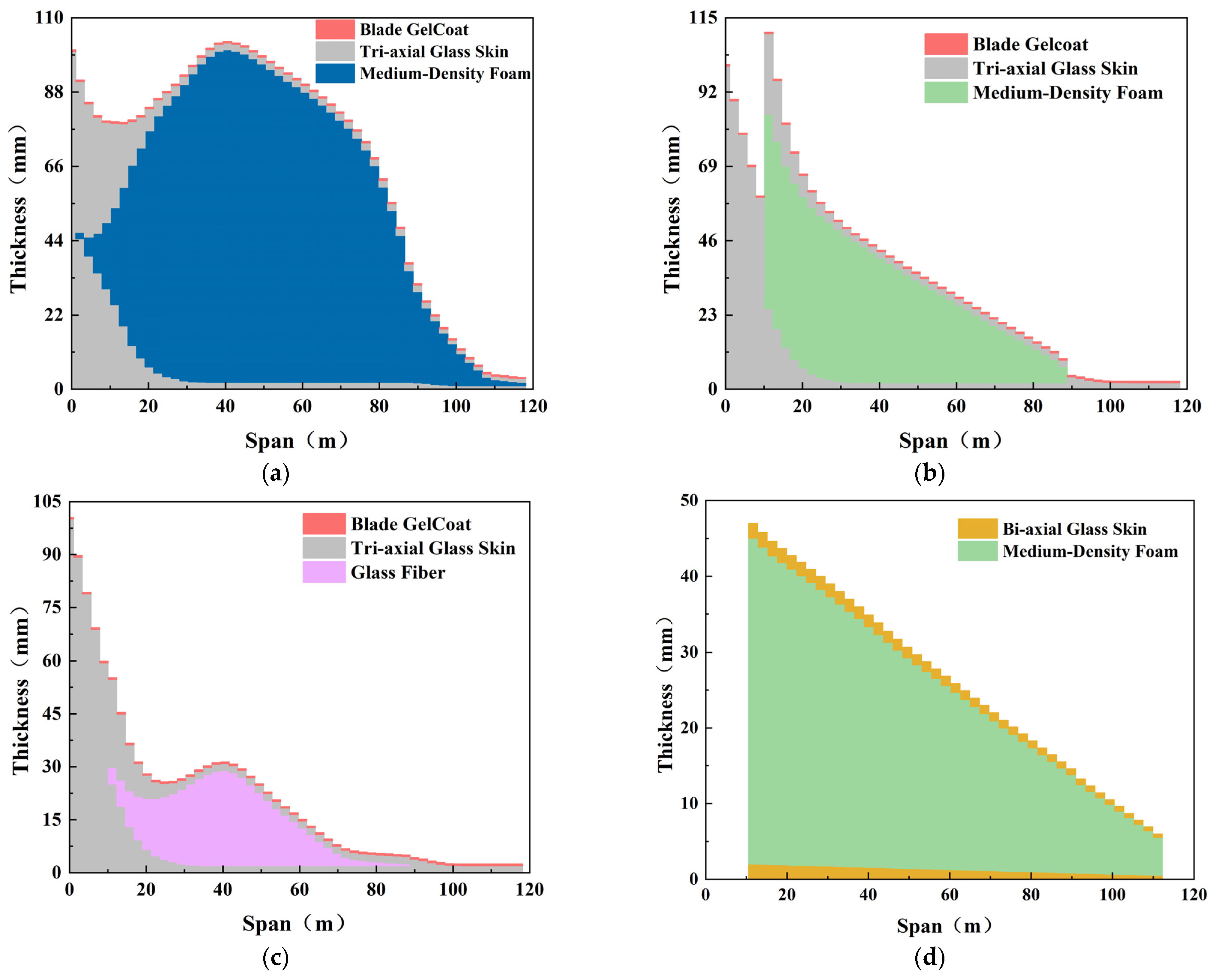
To ensure accurate simulation of the composite blade structure and its dynamic response under different operating conditions, a 15 MW blade model was developed using ANSYS Mechanical APDL. The model incorporates the blade’s actual material properties and region-specific layup schemes. Through precise geometric modeling and mesh generation, a reliable basis was established for subsequent structural analyses and performance optimization. In this model, the material orientation of all elements is set to the spanwise. Furthermore, the ply thickness of each layer is adjusted based on its spanwise position, as shown in Figure 1. This model therefore provides essential support for investigating the blade’s structural characteristics and stress distributions.
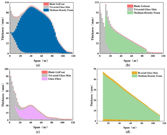
Figure 1.
Spanwise thickness distribution of laminated materials in different regions: (a) spar cap; (b) panel; (c) leading edge and trailing edge; (d) shear web.
The turbine blade model developed in this study includes the aerodynamic external geometry, internal shear webs, and the corresponding composite material parameters. The APDL command stream was used to precisely define the composite properties of each ply. The blade was divided spanwise into 52 regions according to sectional positions; these regions form the fundamental meshing units of the blade. During generation of the small-surface regions, each region was paired with its prescribed layup scheme so that the material properties of each region were accurately reflected in the finite-element model. The model was established using SHELL181 elements. The total mesh count was determined to be 314,960, with a maximum element length of 0.104, a minimum element length of 0.095, and an average mesh quality of 0.975. The resulting FSM of the blade is shown in Figure 2.

Figure 2.
FSM of 15 MW offshore wind turbine blade: (a) distribution of FSM area; (b) blade shear web.
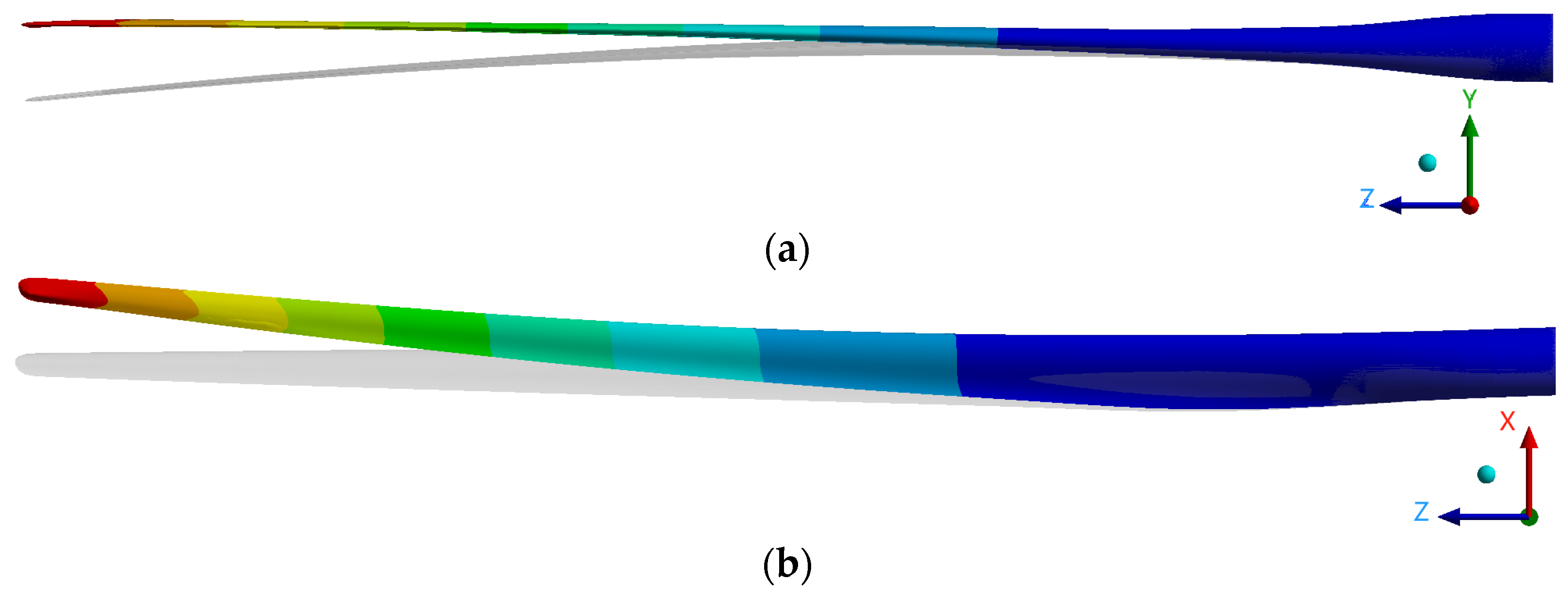
After establishing the FSM, its validity was verified. According to the 15 MW technical report from official design agency, the blade mass is 65,250 kg, and the natural frequencies of the first flapwise and first edgewise modal are 0.555 Hz and 0.642 Hz, respectively. The FSM model constructed here was compared against these reference values; the modal analysis results are presented in Figure 3 and the statistical data are listed in Table 3.
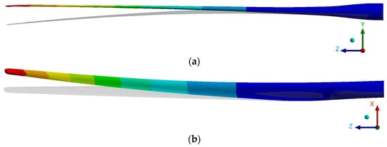
Figure 3.
Results of 15 MW offshore wind turbine blade modal: (a) first flapwise modal shape; (b) first edgewise modal shape.

Table 3.
Comparison of modal analysis results.
Table 3 shows that the computed results from the constructed FSM exhibit only small deviations from the reference documentation, with the maximum deviation occurring in the flapwise modal frequency (3.67%). These results indicate that the developed FSM is highly reliable and suitable to serve as a simulation platform for subsequent TMD investigation.
2.2. Tuned Mass Damper System
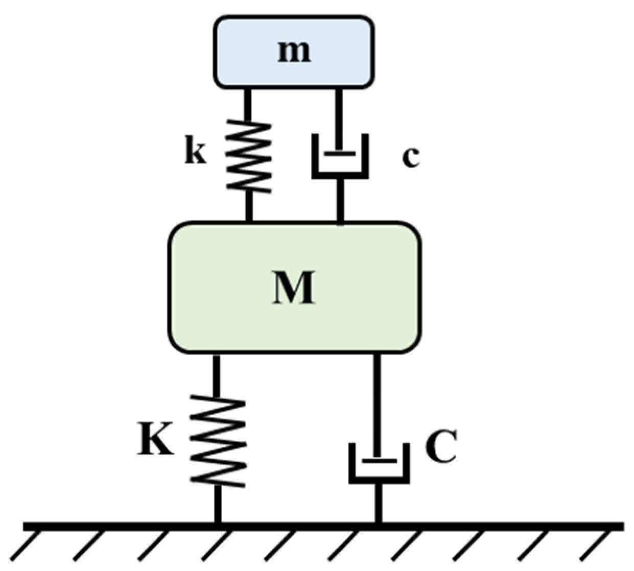
The TMD used for flutter suppression on the blade is based on the classical mathematical model of TMD dynamic response. As shown in Figure 4, the substructure and the primary structure form a coupled dynamic system, and the equations of motion can be written in matrix form, as in Equation (2) [20].
where M and m are the mass of the main structure and substructure, respectively; C and c are the damping of the main structure and substructure, respectively; K and k are the stiffness of the main structure and substructure, respectively; xM and xm are the displacements of the main structure and substructure, respectively; Q(t) is the time-dependent generalized force applied to the main structure.
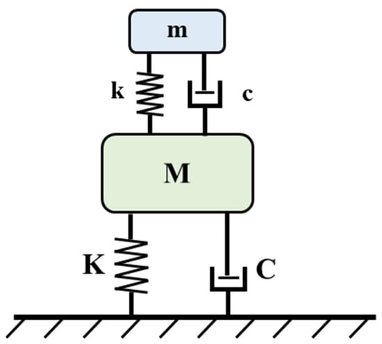
Figure 4.
Typical tuned mass damper system.
In the process of structural vibration analysis, some parameters need to be dimensionless [21], as shown in Equation (3).
where is the natural circular frequency of the primary structure, is the natural circular frequency of the substructure, is the damping ratio of the primary structure, is the damping ratio of the substructure, μ = m/M is the mass ratio, and aI(t) is the generalized inertial acceleration in the time domain. The abstraction of physical quantities into dimensionless parameters, such as the mass and damping ratios, facilitates a more efficient subsequent numerical analysis for parameter optimization.
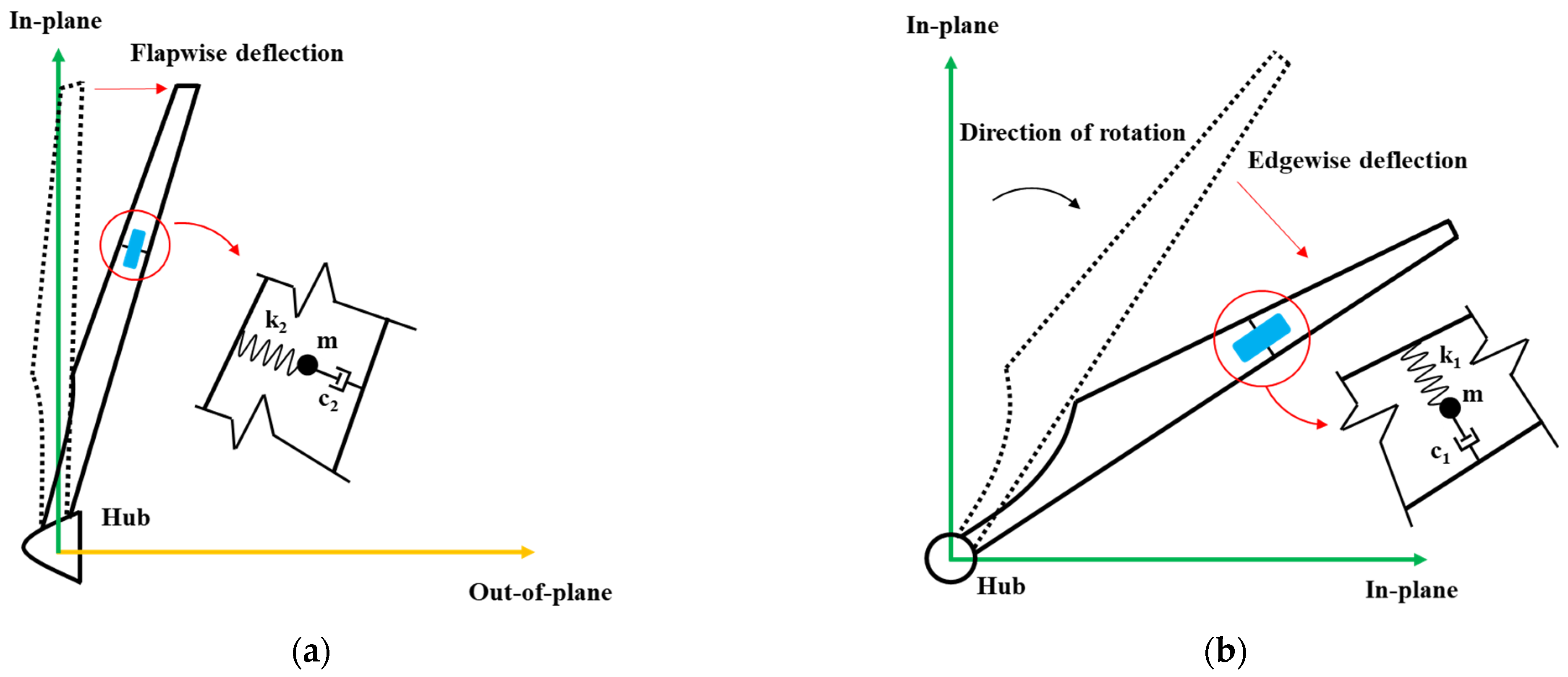
From Equation (2) and Figure 4, it can be seen that a TMD system can reduce the dynamic response of the primary structure by altering the dynamic properties of the substructure; through suitably selected stiffness and damping, vibration energy can be dissipated rapidly. Therefore, in this study, a TMD is adopted to mitigate blade flutter. On the basis of the classical TMD model, a two degree of freedom (2-DOF) TMD system was developed for application to the blade: the system acts separately in the flapwise and edgewise directions and helps to address coupled motions between these two degrees of freedom. A physical simplification of the concept is shown in Figure 5.
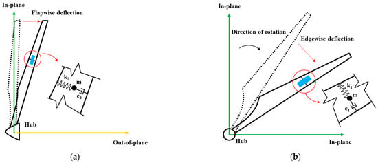
Figure 5.
Coordinates of offshore wind turbine blades with the bidirectional tuned mass damper system: (a) blade flapwise deflection; (b) blade edgewise deflection.
Figure 5 illustrates the implementation scenario of the 2-DOF TMD system on a wind turbine blade. In each controlled direction, the device comprises a pair of spring–damper elements that are connected to a common mass block. The system is installed within the blade cavity and is attached to the shear webs and main spar, which further increases the blade’s bending resistance in both the flapwise and edgewise directions and takes advantage of the blade’s hollow structure. In the FSM of the blade, the operational domain of the 2-DOF TMD system is defined by placing discrete mass points at selected spanwise locations; these mass points are remotely connected to the blade primary structure via spring–dashpot elements. The mechanical model of the wind turbine blade equipped with the bidirectional TMD system is shown in Figure 6a. Bidirectional TMD can be composed of two independent unidirectional TMDs installed orthogonally.

Figure 6.
Blade FSM with TMD system: (a) blade with bidirectional TMD details; (b) deployment configuration of the TMD system on global perspective.
Prior to studying the influence of the bidirectional TMD system on blade vibration characteristics, the design-variable space for mass, damping, and stiffness must be established to identify the optimal parameter combination for flutter suppression. For large continuous structures, the mass ratio of the TMD is typically in the range of 1~5% [22]. Accordingly, in this study, the mass-ratio design space for the bidirectional TMD was set to 1%, 3% and 5%. When conducting parameter analyses, we did not employ a simple full factorial or one-factor-at-a-time approach to generate the numerical simulation dataset; instead, numerical optimization methods were used to determine the remaining optimal parameters corresponding to each mass ratio. The amplification factor under dynamic loading, with the bidirectional TMD installed, is defined as the ratio of the main-structure displacement amplitude to the static maximum displacement [23], as given in Equation (4).
where α is the ratio of the natural frequency of the substructure to that of the primary structure, and β is the ratio of the load frequency to the natural frequency of the primary structure. According to the definition of the dynamic amplification factor (R), a smaller value of R corresponds to a smaller vibration amplitude of the primary structure. Therefore, for a given mass ratio μ, the remaining parameters are adjusted with the objective of minimizing R. This process yields the optimal frequency ratio and optimal damping ratio, as shown in Equation (5):
The mass, stiffness, and damping of the TMD can then be expressed as follows:
It should be noted that owing to geometric and material anisotropy of the blade, the optimal stiffness and damping values for the flapwise and edgewise directions must be computed separately according to the modal frequencies in each direction.
In addition to designing the internal parameter space of the TMD, the position of the flutter suppressor must be determined. Based on the requirement that the TMD must have sufficient travel, and considering that the chordwise spacing of the blade decreases from root to tip, the TMD system was arranged spanwise between 12% and 70% of the blade span. Its chordwise positions were set in the range 3.2 m to 5.7 m and its through-thickness positions were in the range of 0.9 m to 3.6 m, which satisfy the necessary travel requirements. The layout of the TMD system within the blade FSM is shown in Figure 6b.
2.3. Blade Load Application
The loading protocol for the blade in this study was configured according to the full-scale structural testing stage of the certification procedure for blades [24]. Existing full-scale structural testing commonly employs a centrifuge as the excitation source; the magnitude and application point of the excitation, and whether counterweights are needed, are determined in accordance with the relevant standards [25]. The GL 2010 wind turbine specification requires that, during full-scale structural testing, the spanwise bending-moment distribution applied to the blade should follow the actual in-service bending-moment distribution so that the experimental moment field more closely represents the aerodynamic load distribution [26].
Industry statistics for blade testing indicate that excitation sources are typically located at spanwise positions between 57% and 73% [27,28,29], and that the excitation force is commonly in the range of 8~20% of the blade self-weight [30,31,32]. Accordingly, in this study, the excitation source was placed at 70% span of the 15 MW blade and the excitation magnitude was set to 10% of the blade self-weight. Four excitation scenarios were considered, as described in Table 4.

Table 4.
Harmonic response analysis loading condition.
For the first three scenarios, the scalar magnitude of the excitation force is held constant; the vector character of the excitation is varied to target the flapwise and edgewise directions and to include cases with coupled flapwise–edgewise action. In addition, the phase difference in the excitation forces is taken into account to investigate the bending–bending coupling vibration of offshore ultra-long flexible blades.
The wind-induced response of the wind turbine blade was obtained through the aforementioned excitation method. Subsequently, the vibration characteristics under this wind loading were analyzed using the harmonic response method. The vibration divergence condition identified under wind loading was utilized as the flutter condition. Finally, the flutter suppression effectiveness of a bidirectional TMD on the blade was investigated.
3. Blade Flutter Suppression Performance
To perform an in-depth analysis of the mechanism of a bidirectional TMD applied to an ultra-long flexible blade and to investigate the influence of multivariate parameters on flutter suppression, this study introduces the flutter suppression rate (FSR). The FSR serves as a metric to evaluate the flutter suppression performance of both bidirectional and unidirectional TMD on the blade. The calculation method is provided in Equation (7):
where η represents the FSR; JWithout TMD and JWith TMD are the root mean square (RMS) values of the blade’s vibration displacement without and with the TMD installed, respectively. The variable x is the time history of the blade displacement, is its mean value over the integration period, and T is the total duration of the time-series analysis.
3.1. Blade Flutter Characteristics Analysis
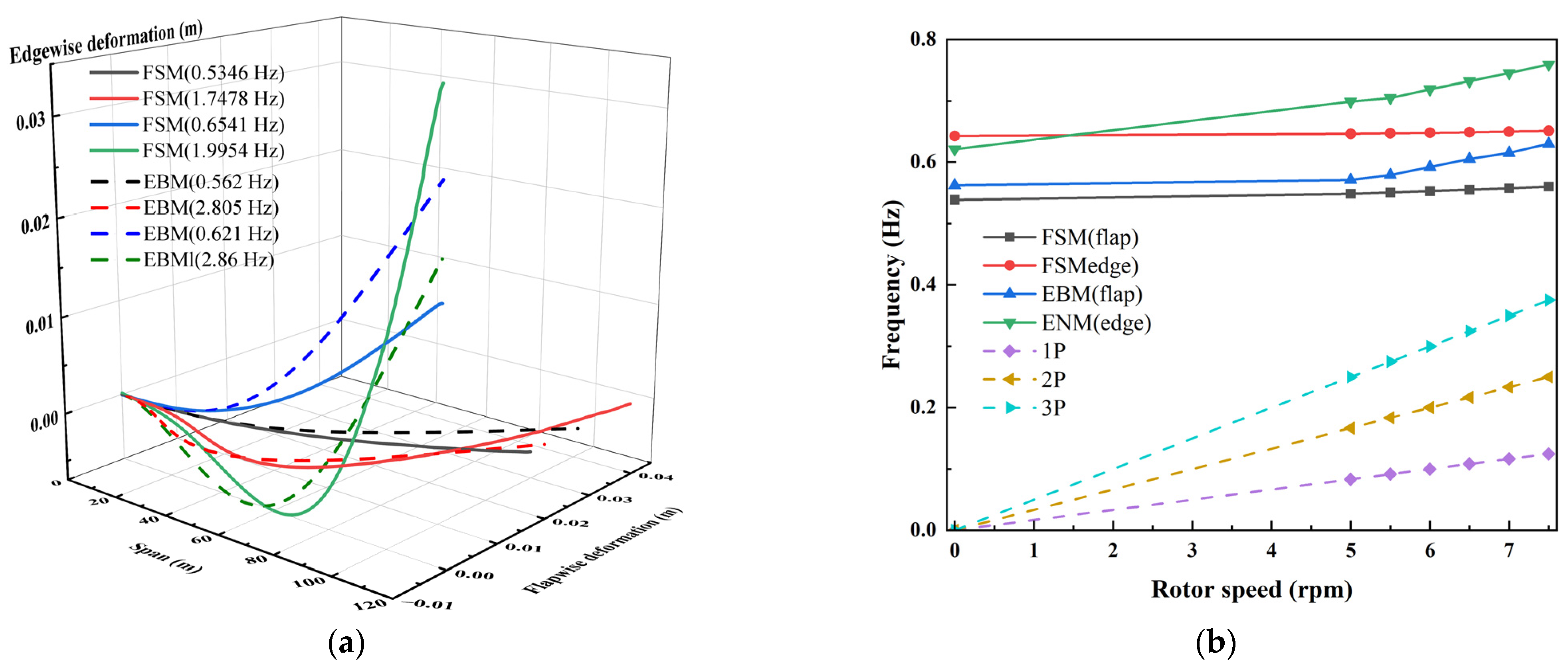
Prior to conducting the vibration suppression investigation on blades of ultra-large wind turbines, an analysis of the inherent dynamic response characteristics of the 15 MW wind turbine blade was performed to broaden the research scope. This serves as the foundation for subsequent explanations and analyses of flutter occurrence and suppression mechanisms. This study primarily encompasses modal analysis, harmonic response analysis, and free decay motion from three perspectives, with comparisons against results from the commonly used EBMs in the industry. The modal analysis results are first compared. As shown in Figure 7a, the deformation of the blade modal shapes in the flapwise and edgewise directions from root to tip are presented.
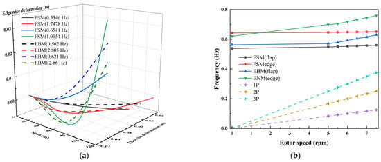
Figure 7.
Comparison between FSM and EBM: (a) 15 MW blade modal shape; (b) Campbell diagram of blade.
From Figure 7a, it is evident that, at the first-order modal frequency, the relative errors between the EBM and the FSM in the flapwise and edgewise directions are 5.12% and 4.60%, respectively, which are small and within an acceptable range. However, in the second-order modal frequency comparison, the relative errors in the flapwise and edgewise directions are 60.5% and 43.2%, respectively, indicating that the EBM indeed suffers from significant higher-order nonlinear errors. Regarding blade modal shapes, the spanwise deformation distributions in the flapwise and edgewise directions are highly similar. The result shows that the EBM generally overestimates the first-order modal deformation while underestimating the second-order modal deformation, suggesting that simplified models like the EBM tend to allocate energy predominantly to lower-order modes.
Given the characteristic of smaller modal deformations in ultra-long flexible blades, the coefficient of determination R2 was employed to evaluate the consistency between the FSM and EBM results. R2 is a comprehensive metric for evaluating the goodness of fit of a model. Calculations yield R2 values of 0.27 and 0.28 for the first-order flapwise and edgewise modes, respectively, and 0.85 for both the second-order flapwise and edgewise modes. These modal shape comparisons further underscore the necessity of using a high-fidelity FSM for blade flutter investigation.
Additionally, the blade’s vibration characteristics are influenced by the rotor rotation frequency. To investigate the blade’s sensitivity to external excitations, Campbell diagrams were used for comparative analysis, incorporating both dynamic stiffening and rotational softening effects. Campbell diagrams serve as a reference for verification during the blade structural design phase, providing guidance on blade structural properties.
Figure 7b illustrates the variation in blade frequency at different rotational speeds. Since the 15 MW wind turbine operates in the maximum wind energy capture phase below 5 rpm and rapidly transitions through this stage during actual operation, investigating the influence of rotational speeds within this range is not representative of practical conditions. Therefore, the study of rotational speed effects on the blade commences from 5 rpm. When the blade is modeled using the EBM, the frequency increases significantly with rising rotational speed, indicating the influence of the centrifugal stiffening effect. However, when the blade is modeled using the FSM, the frequency increases only slightly with rotational speed, demonstrating that the consideration of rotary softening effects mitigates the enhancement induced by dynamic stiffening.
Significant discrepancies persist between the EBM and the FSM, with average relative errors of 7.53% and 10.78% in the flapwise and edgewise directions, respectively. These differences further confirm the necessity of employing an FSM to describe the dynamic responses of ultra-large wind turbine blades. Regarding the influence of rotor frequency, neither the EBM nor the FSM exhibit the coincidence between the modal frequencies and the rotation frequency, indicating that the IEA 15 MW blade design initially accounted for the impact of rotor speed on inherent blade properties, thereby avoiding resonance risks induced by rotation frequency, which also demonstrates that the influence of rotational factors on blade vibration in terms of frequency is minimal.
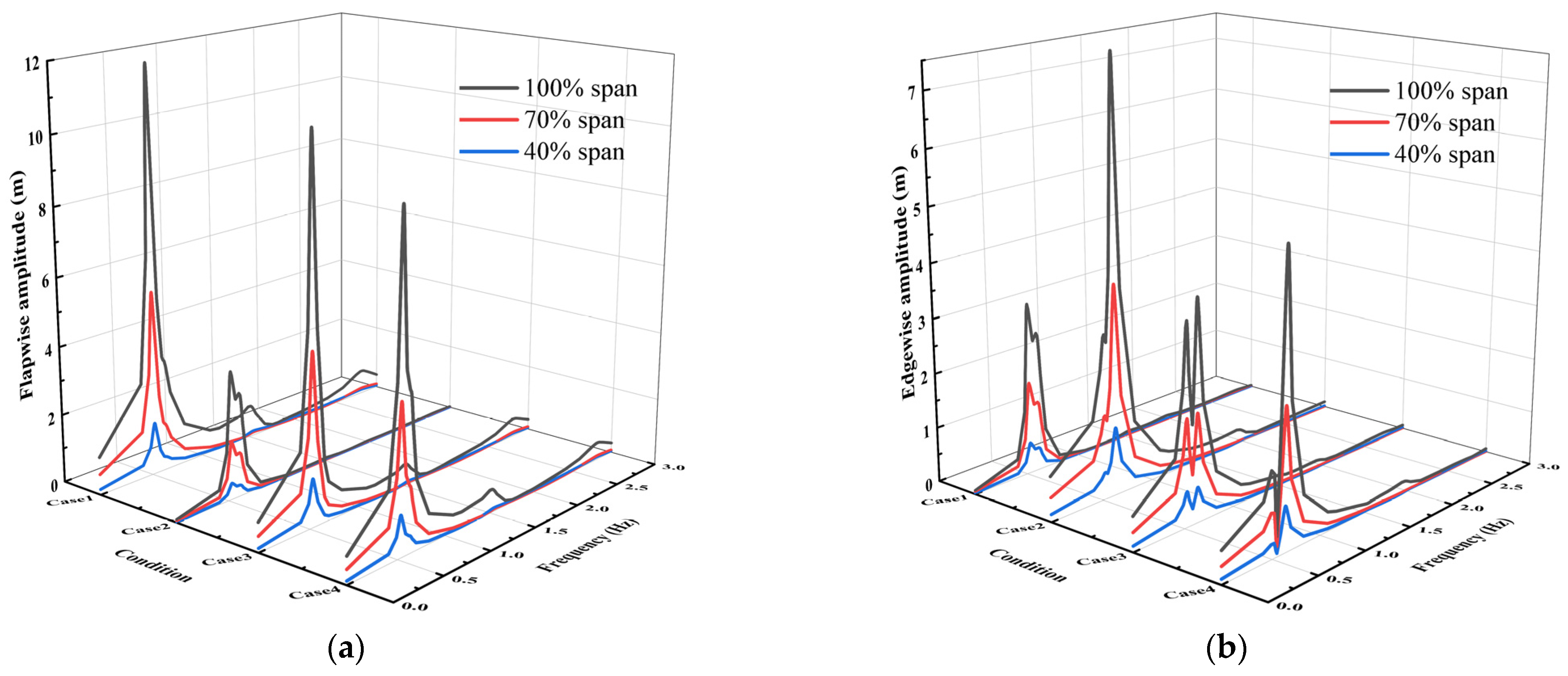
Harmonic response analysis was conducted to study the vibration response characteristics of the 15 MW blade under excitations at different frequencies. Three monitoring points were selected from the blade root to tip, corresponding to 40%, 70%, and 100% of the total blade length. The results are shown in Figure 8.
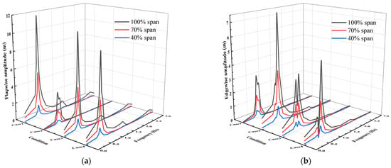
Figure 8.
Relationship between blade deflection amplitude and frequency: (a) flapwise deflection amplitude; (b) edgewise deflection amplitude.
The results reveal significant differences in excitation outcomes from the same source applied in different directions. Statistically, regardless of the excitation force type, the maximum tip amplitude is approximately 6 times that at the 40% spanwise position in the flapwise direction and 5 times in the edgewise direction, indicating that the nonlinear deformation effects along the span are insensitive to changes in the direction and magnitude of external excitation forces. Under flapwise excitation, the tip flapwise amplitude exceeds the tip edgewise amplitude under edgewise excitation by 52.4%, demonstrating that the geometric configuration and material stiffness of ultra-long flexible blades provide enhanced vibration suppression capability in the edgewise direction.
In all four cases, amplitude extrema readily occur near the first-order flapwise and edgewise modal frequencies, with the amplitude–frequency response curve in the edgewise being most pronounced and exhibiting a “dual-peak” distribution. The response frequency for the maximum flapwise amplitude is consistently close to the first-order flapwise frequency, whereas the maximum edgewise amplitude response frequency may not be closest to the first-order edgewise frequency. Although edgewise excitation can also induce flapwise amplitude extrema near the first-order edgewise modal frequency, the maximum peak in the flapwise direction under Case 1 remains near the first-order flapwise modal frequency. This is attributed to the lower flapwise stiffness compared to edgewise stiffness in long flexible blades, allowing excitations near the flapwise modal frequency to still provoke maximum edgewise amplitudes, indicating that long flexible blades are more prone to vibrations at the first-order flapwise frequency.
The response in higher-order modal shapes differs markedly from that in lower-order ones. Regardless of flapwise or edgewise excitation, higher-order amplitude extrema are induced only in the same direction and near the higher-order modal frequencies, suggesting minimal coupling deformations among higher-order modes.
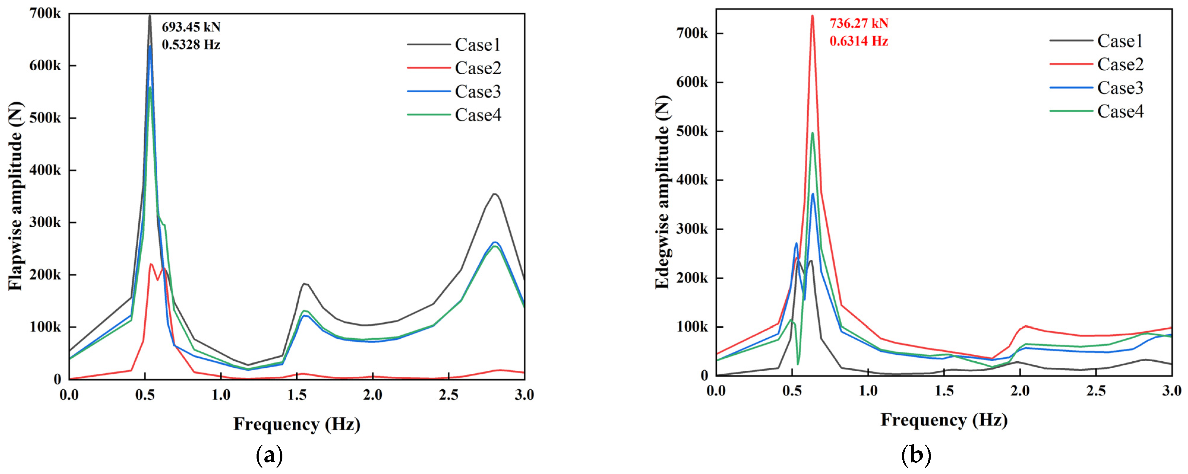
Figure 9 presents the root support force reaction responses. Unlike the deflection relationships in the flapwise and edgewise, the maximum reaction force in the edgewise direction exceeds that in the flapwise. This indicates that, although the slightly higher natural frequency in the edgewise direction requires greater input energy to excite the mode, resulting in larger root force reactions to stabilize the blade, the greater edgewise stiffness still limits the maximum edgewise deflection to less than the maximum flapwise deflection. Furthermore, the phase of the excitation force significantly affects the root force reactions differently in the flapwise and edgewise. In the flapwise direction, Case 3 yields larger force reactions near the first-order natural frequency, while Case 4 does so near the second-order natural frequency. In the edgewise, Case 4 consistently produces larger force reactions.
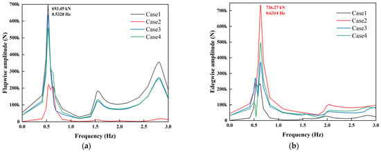
Figure 9.
Relationship between blade root force reaction amplitude and frequency: (a) flapwise force reaction amplitude; (b) Edgewise force reaction amplitude.
This phenomenon arises because the first-order flapwise mode involves in-phase bending of the entire blade; when the excitation force is also in-phase, the excitation force maximizes, contributing uniformly to overall bending without cancellation, most effectively exciting first-order modal resonance and generating the largest root force reaction. In contrast, the second-order flapwise mode includes anti-phase nodes; the phase difference in Case 4 aligns the excitation force distribution with alternating directions, matching the second-order mode bending and more effectively exciting it, thus requiring greater root force reaction in Case 4 than in Case 3. This illustrates that, for the ultra-long flexible blades of offshore wind turbines, complex structural characteristics render blade responses non-monotonically dependent solely on excitation frequency but also on the matching between excitation force and blade modal shape distributions.
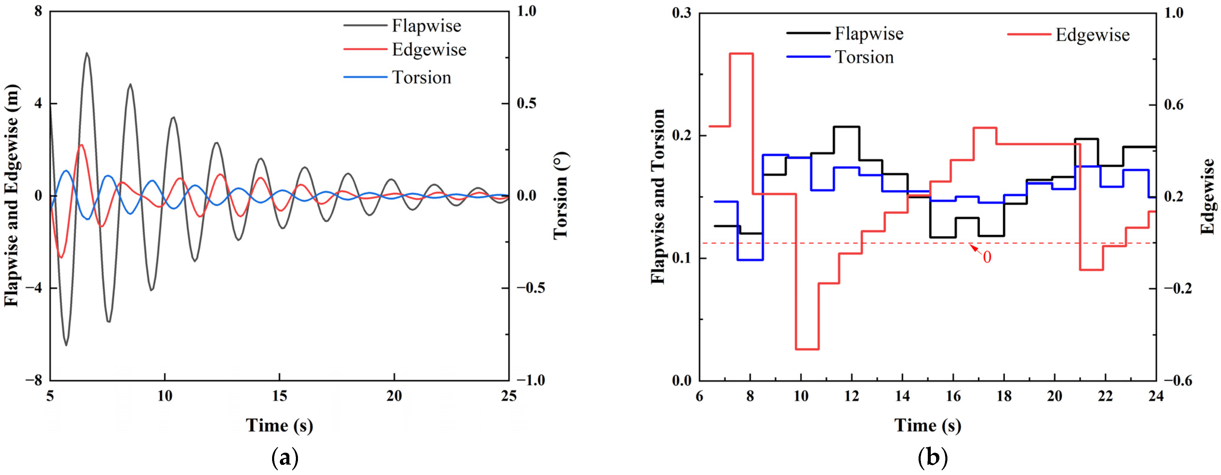
In the analysis of vibration characteristics during free decay motion, preload offsets were set based on the actual stable-phase amplitudes from harmonic responses. The analysis includes deflections in different directions, as well as physical quantities such as force reaction and moment reaction. The results are shown in Figure 10.
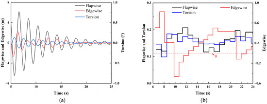
Figure 10.
Blade tip response under free vibration motion: (a) blade tip deflection; (b) attenuation coefficient.
Figure 10a indicates that, after removal of external forces during blade vibration, the phase changes in the tip flapwise and edgewise directions are relatively similar, while the tip torsional direction remains consistently anti-phase with the flapwise direction, signifying a significant motion coupling between flapwise and torsional degrees of freedom. Since the prototype IEA 15 MW wind turbine blade does not incorporate bend–twist coupling for load reduction, blade movement toward the downwind direction is accompanied by an increased angle of attack. This suggests that flapwise deformations in long flexible blades under wind field operation can lead to further increases in wind loads, potentially sustaining or amplifying flutter amplitudes during exacerbation. This indirectly underscores the necessity of load reduction designs and confirms the propensity of long flexible blades to generate self-excited vibrations under wind conditions.
Additionally, the edgewise deflection exhibits noticeable periodic changes in the 8~10 s, with subsequent amplitude initially increasing before decreasing, indicating energy transfer from other directions to the edgewise direction during that period, thereby augmenting edgewise amplitude. To filter initial-stage disturbances, the full-time-domain decay coefficients were calculated from 6 s onward, as shown in Figure 10b. During 8~10 s, the flapwise and torsional decay coefficients first increase and stabilize in 10~12 s, while the edgewise decay coefficient decreases to negative values in the same interval, aligning with the energy transfer observations across different degrees of freedom from the prior time-domain analysis.
3.2. Unidirectional TMD Analysis
The flutter characteristics of the ultra-long flexible blade with unidirectional TMDs were investigated, beginning with modal analysis of the modified blade. The influences of TMD action direction and installation position on blade flutter were considered, with a mass ratio of 3% and stiffness and damping obtained directly from Equation (6). The results are shown in Figure 11.
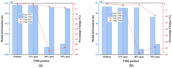
Figure 11.
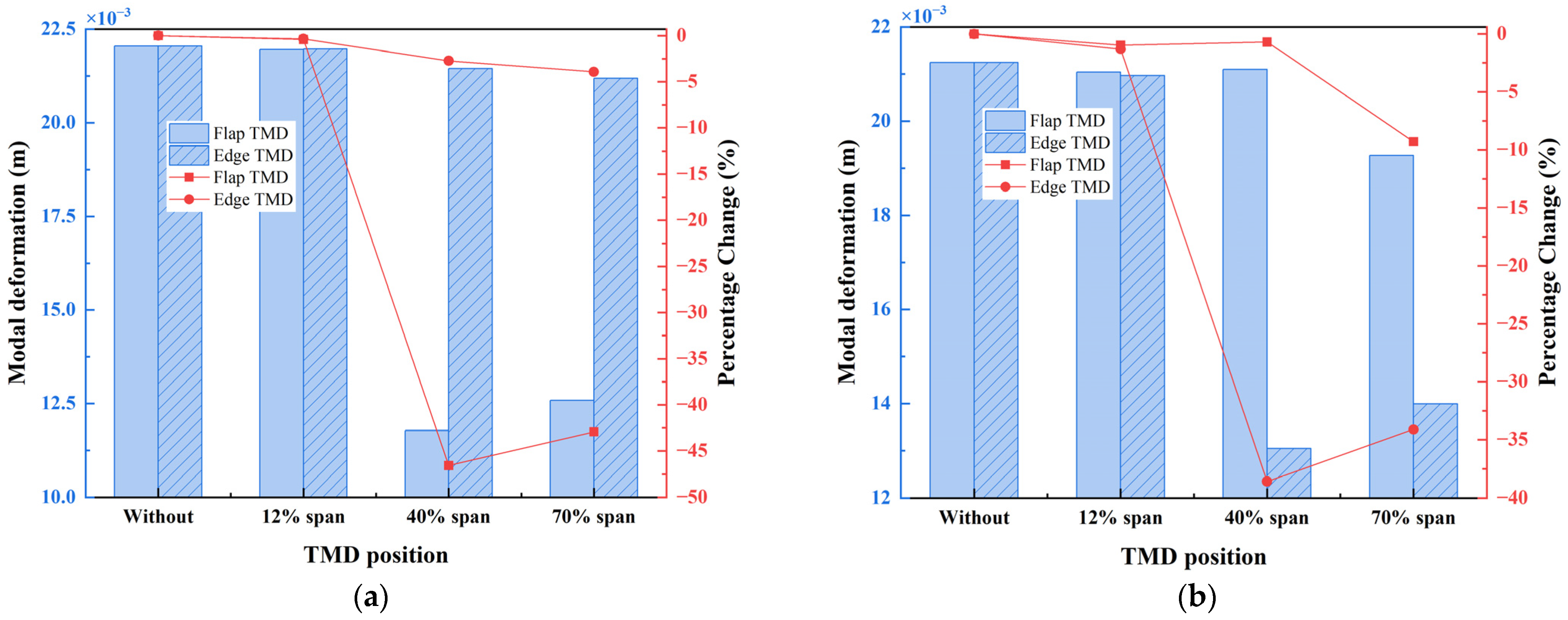
Blade modal maximum deformation with unidirectional TMD: (a) flapwise modal; (b) edgewise modal.
Regarding modal deformation, installing TMDs in any direction reduces the maximum deformation. Flap-TMDs primarily affect flapwise modal deformation, while Edge-TMDs primarily affect edgewise modal deformation. As the TMD installation position increases along the span, the maximum deformation in the primary modes for the blade with Flap-TMDs or Edge-TMDs initially decrease and then increase, while the maximum deformation in the other direction continue to decrease. Statistically, in the action direction, the Flap-TMD achieves the lowest modal offset at the 40% spanwise position, reducing it by 46.57% compared to the original blade. The Edge-TMD also achieves the lowest at the 40% spanwise position, with a 38.60% reduction.
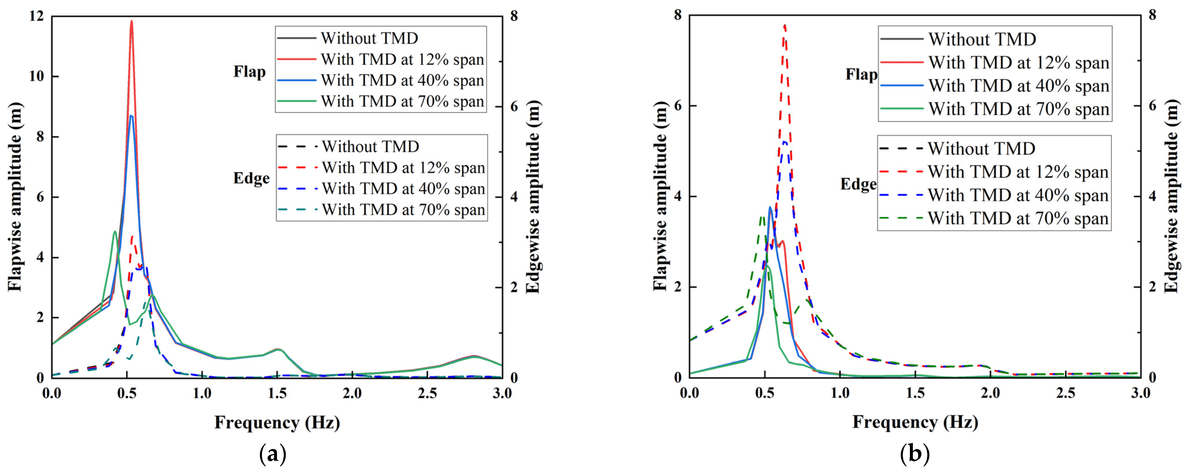
For harmonic response analysis, for the blade with a Flap-TMD, excitations are applied under Cases 1 and 3; for an Edge-TMD, Cases 2 and 3 are used. The simulation results are as follows:
From Figure 12, the blade amplitude responses follow patterns similar to those of modal deformation with TMD position variations. Regardless of excitation direction, at the 12% spanwise position, the frequency response curves for tip stable amplitudes in both flapwise and edgewise directions closely align with those of the original blade, indicating limited effectiveness of TMDs at this position.
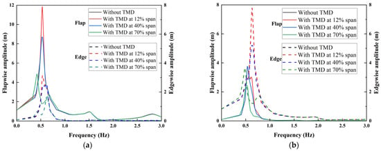
Figure 12.
Relationship between tip amplitude and frequency of blade with unidirectional TMD: (a) Case 1; (b) Case 2.
With increasing spanwise position, under Flap-TMDs, the flapwise amplitudes decrease by 0.02%, 26.48%, and 58.92% relative to the baseline, while the edgewise amplitudes decrease by 0.04%, 18.44%, and 46.13%. Under Edge-TMDs, the flapwise amplitudes decrease by 0.005%, −1.4%, and 33.61%, while the edgewise amplitudes decrease by 0.1%, 33.01%, and 53.2%.
The statistical results reveal that unidirectional TMDs effectively attenuate vibration amplitudes in their action direction, with more pronounced suppression near the tip. However, in the other degree of freedom, effective reduction occurs only at the 70% spanwise position, and in some positions, amplitudes may even increase, indicating stringent operational environment requirements for unidirectional TMDs.
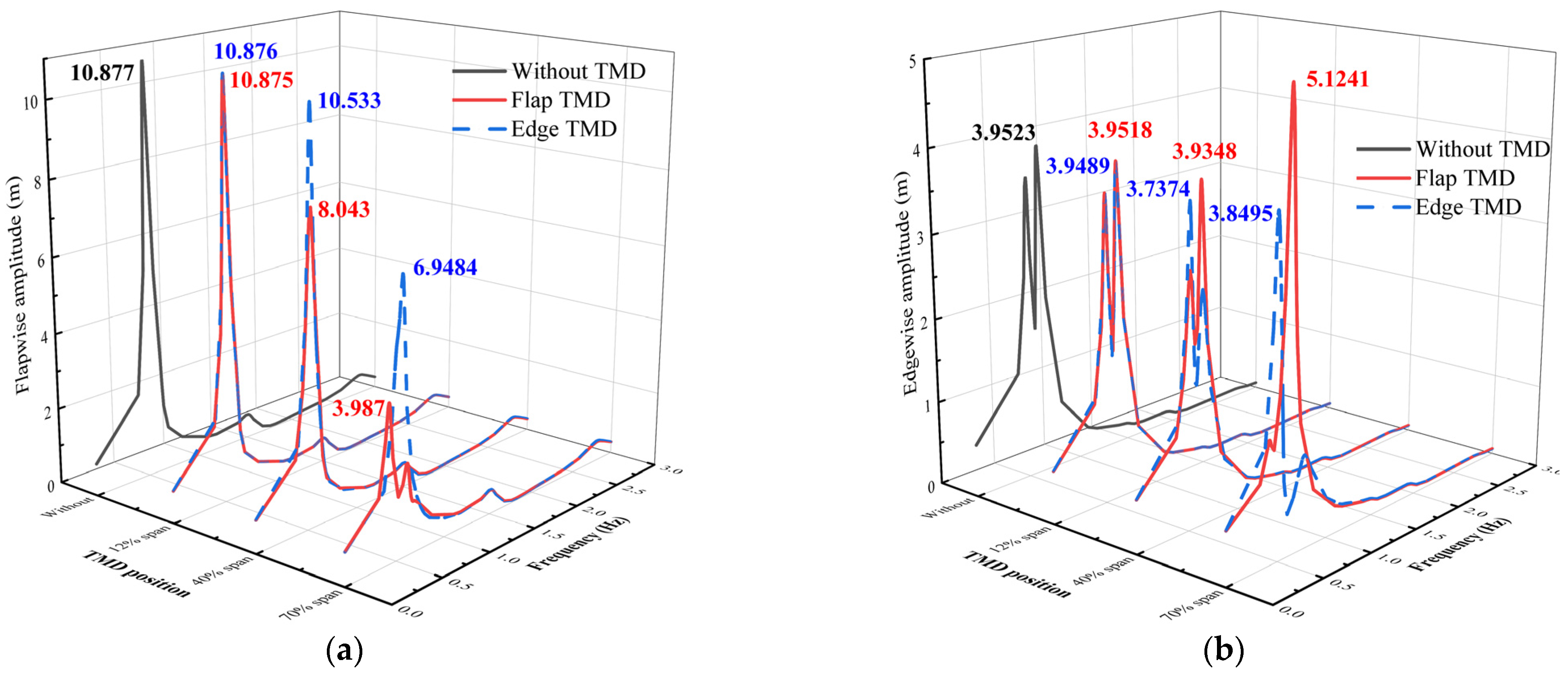
In Case 3 simulations, where excitation forces couple flapwise and edgewise directions, higher demands are placed on the flutter suppression capability of unidirectional TMD in ultra-long flexible blades. Figure 13a shows that, as the TMD position extends spanwise, maximum amplitudes of blade under both Flap-TMDs and Edge-TMDs gradually decrease, with reductions of 0.018%, 26.05%, and 63.34% for installing a Flap-TMD, and 0.009%, 3.16%, and 36.12% for installing an Edge-TMD.
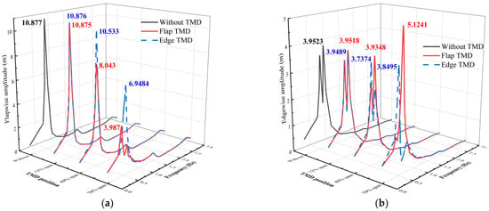
Figure 13.
Tip response of blade with unidirectional TMD under Case 3: (a) flapwise; (b) edgewise.
At the 70% spanwise position of blade, the effective frequency intervals differ: Flap-TMDs significantly reduce flapwise and edgewise amplitudes in the forward 0.5~0.7 Hz range, while Edge-TMDs act in a slightly later interval, but both yield nonlinear and accelerating reductions in maximum blade amplitudes.
Figure 13b indicates that spanwise position changes have limited effects on reducing maximum stable-state amplitudes, and Flap-TMDs at the 70% spanwise position even cause an abrupt increase in the blade’s edgewise maximum amplitude, heightening flutter risks for the offshore blade. This adverse effect relates to the “dual-peak” distribution of the original blade’s edgewise response under coupled excitation, where tip edgewise deflection increases twice near the first-order flapwise and edgewise frequencies.
Statistically, with spanwise extension, edgewise maximum amplitudes of blade under Flap-TMDs decrease by 0.013%, 0.44%, and −29.68%, and under Edge-TMDs, by 0.086%, 5.44%, and 2.60%. Installed unidirectional TMDs can attenuate amplitudes at their corresponding frequency but tends to fail to address the other direction or even excite larger amplitudes.
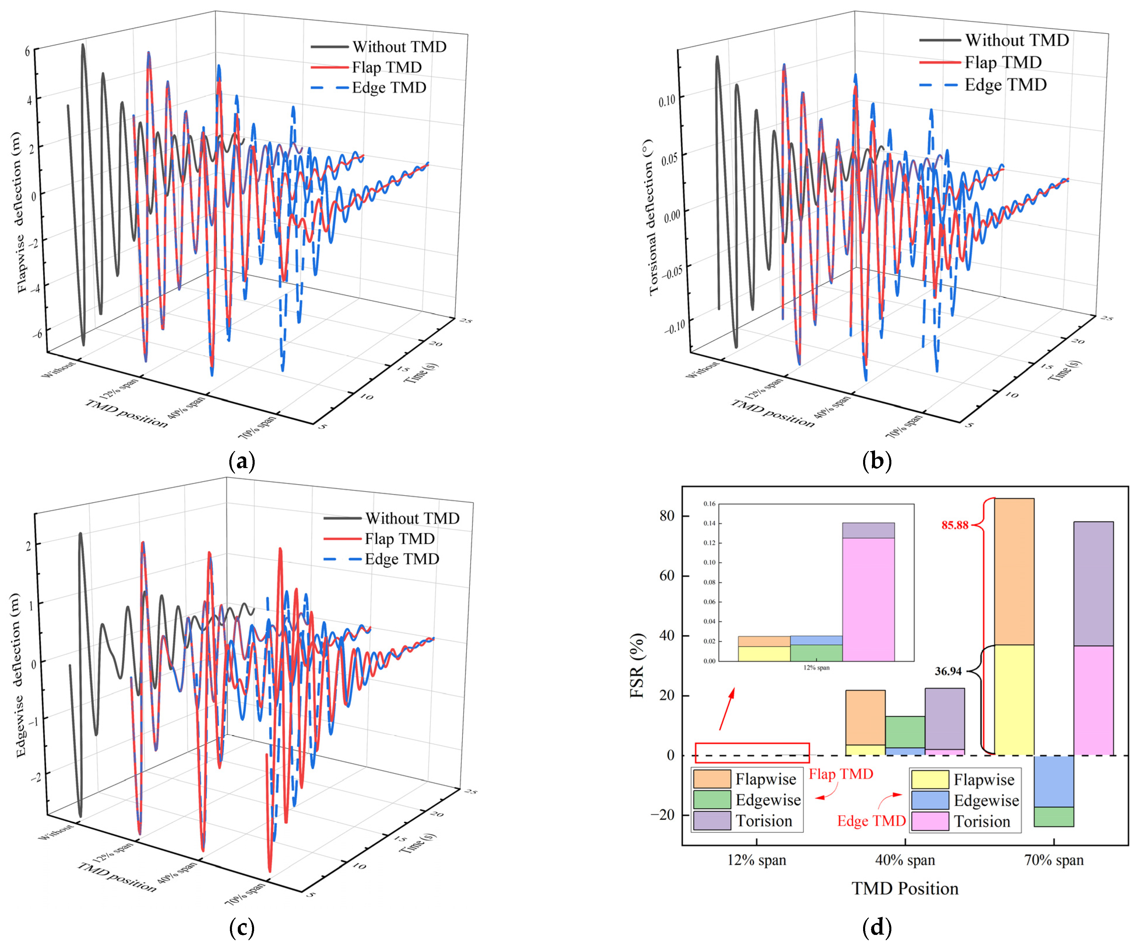
From Figure 14a,b, blades with Flap-TMD or Edge-TMD exhibit similar influences in flapwise and torsional deflections: Flap-TMDs effectively reduce vibrations not only in their own direction but also in torsion, further confirming strong coupling between flapwise and torsional degrees of freedom in ultra-long flexible blades. In Figure 14c, vibration levels do not decrease continuously with increasing TMD position; at the 70% spanwise position, Flap-TMDs increase the blade’s amplitude, while Edge-TMDs reduce it but result in slower decay of the deflection fluctuation curves, indicating that TMD installation affects energy transfer from the edgewise to the flapwise and torsional directions.
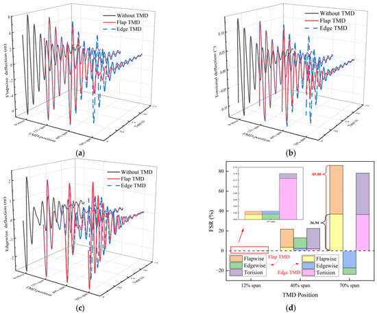
Figure 14.
Blade with unidirectional TMD simulation result under free vibration motion: (a) flapwise deflection; (b) torsional deflection; (c) edgewise deflection; (d) FSR statistics.
This is indirectly supported by Figure 14d, where the FSR represents flutter suppression effectiveness post-TMD installation; negative rates imply intensified vibrations compared to the original blade. At the 12% spanwise position, FSRs are generally below 0.2% but positive, indicating poor suppression. At the 70% spanwise position, the flapwise FSR is 85.88%, which is the highest, while torsional vibration is effectively suppressed, but the edgewise FSR is negative, signifying more intense edgewise flutter response.
The above findings indicate that ultra-long flexible blades possess higher inherent flutter risks and more complex flutter characteristics. TMD installation no longer follows the conventional notion that longer action distances yield better results, differing significantly from traditional small-sized “rigid” blades. This also highlights the limited applicability of unidirectional TMD, rendering them unsuitable for flutter suppression in ultra-long flexible blades. Consequently, bidirectional TMDs should be employed for further flutter suppression studies in such blades.
3.3. Bidirectional TMD Analysis
In the study of flutter suppression for blades with bidirectional TMD, a comprehensive analysis was conducted to investigate the influence of TMDs with mass ratios of 1%, 3%, and 5% on blade flutter suppression. The mechanisms by which unidirectional and bidirectional TMDs affect blade flutter characteristics were compared.
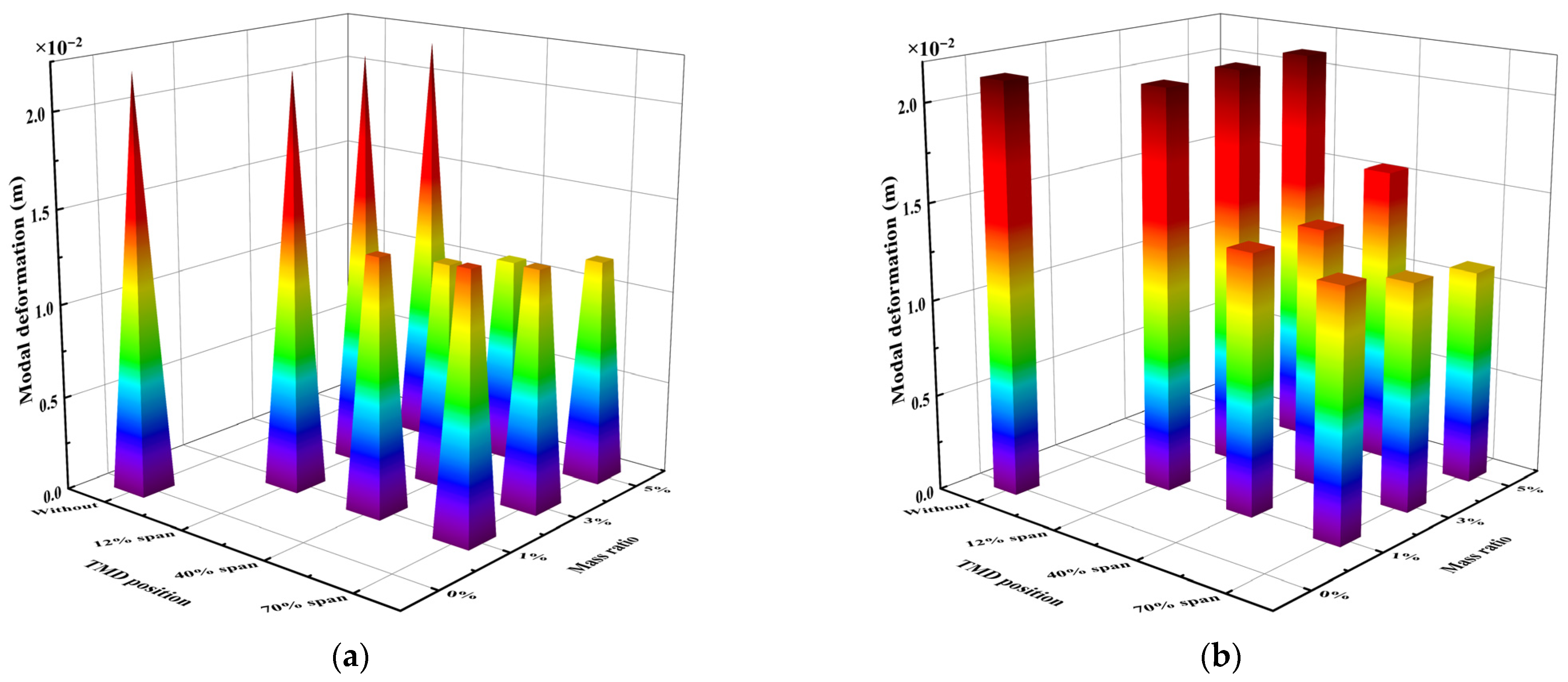
First, the modal deformations of blades with bidirectional TMDs were evaluated under different mass ratios and installation positions. As shown in Figure 15, the installation of TMDs effectively reduced the deformation of ultra-long flexible blades in both the flapwise and edgewise directions. Similar to unidirectional TMDs, when bidirectional TMDs were installed at the 12% spanwise position, the reduction in modal deformation was limited, and the ability to suppress deformation weakened further with increasing mass ratio. This indicates that even bidirectional TMDs struggle to achieve significant vibration suppression potential near the blade root. With higher TMD mass ratios, modal deformations decreased at the 40% and 70% spanwise positions in the flapwise direction, with a faster rate of change at the 40% position. In the edgewise direction, modal deformation continued to decrease at the 70% position, but increased at the 40% position.
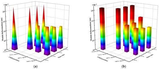
Figure 15.
Blade modal maximum deformation with bidirectional TMD: (a) flapwise; (b) edgewise.
When bidirectional TMDs were installed farther from the root, modal deformations in the flapwise direction initially decreased and then increased, with this trend becoming more pronounced at higher mass ratios. In the edgewise direction, modal deformations consistently decreased, with the reduction becoming more linear as the mass ratio increased. These results highlight that ultra-long flexible blades exhibit strong nonlinear responses, significant differences across degrees of freedom, and highly uncertain variation patterns, making the behavior of blades with TMDs more complex.
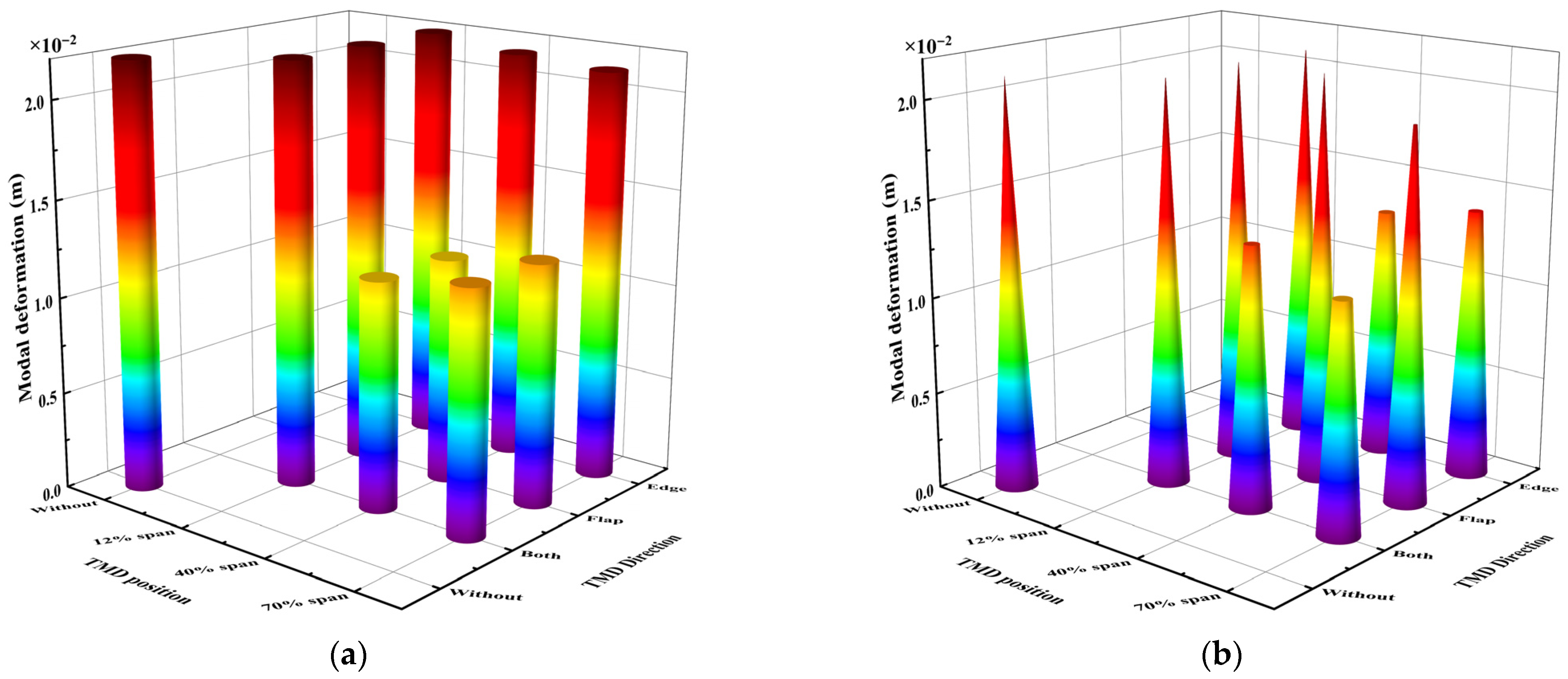
As shown in Figure 16, comparing unidirectional and bidirectional TMDs, unidirectional TMDs were found to reduce the blade’s modal deformation effectively in only one direction, with minimal impact in the other direction. Blades with bidirectional TMDs achieved pronounced reductions in modal deformation along both principal directions; the extent of reduction matched that observed for blades fitted with unidirectional TMDs operating in their primary suppression direction.
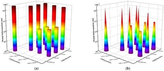
Figure 16.
Blade modal deformation: unidirectional TMD versus bidirectional TMD: (a) flapwise; (b) edgewise.
Relative to the original blade, unidirectional TMD reduced flapwise modal deformation by up to 46.57%, while bidirectional TMD achieved 46.08% under the same mass ratio. In the edgewise direction, unidirectional TMDs reduced modal deformation by up to 38.60%, while bidirectional TMDs achieved 44.10%, demonstrating that bidirectional TMDs offer superior flutter suppression potential for ultra-long flexible blades.
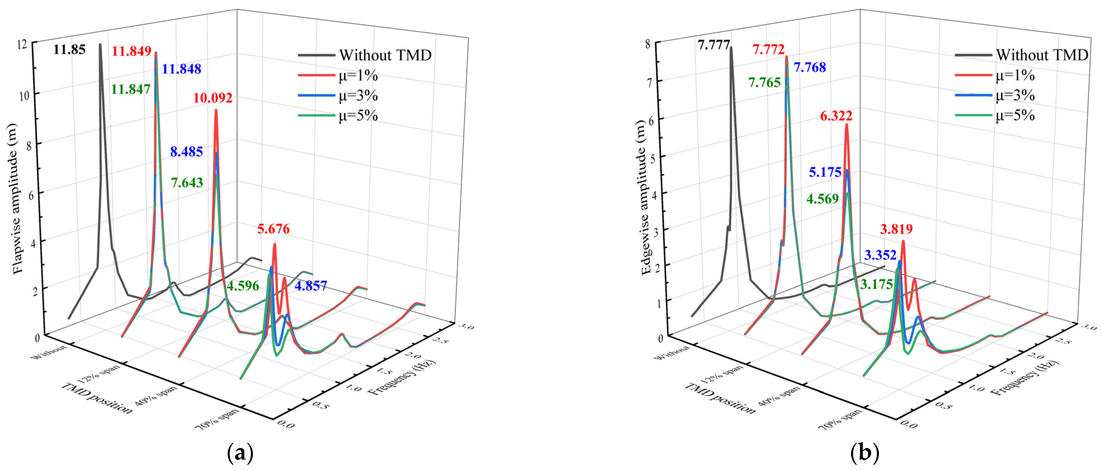
For 15 MW blades with unidirectional TMDs, stable reductions in vibration amplitude were observed in the TMD’s action direction. Therefore, the amplitude variation patterns of blades with bidirectional TMD were investigated, with the results shown in Figure 17.
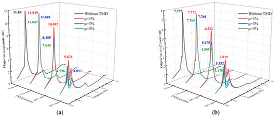
Figure 17.
Relationship between tip amplitude and frequency of blade with bidirectional TMD: (a) Case 1; (b) Case 2.
Figure 17 illustrates that bidirectional TMDs effectively suppressed vibration amplitudes in both flapwise and edgewise directions for ultra-long flexible blades. As the TMD mass ratio or installation distance increased, the maximum stable amplitude decayed nonlinearly and acceleratingly. Compared to blades with unidirectional TMDs, the maximum flapwise amplitude reductions under Case 1 were 0.05%, 3.03%, and 0.22%, while the maximum edgewise amplitude reductions under Case 2 were 0.009%, 0.676%, and 8.89%. These results indicate that bidirectional TMDs further enhance the offshore blade’s ability to mitigate flutter risks, even in the unidirectional TMD action direction.
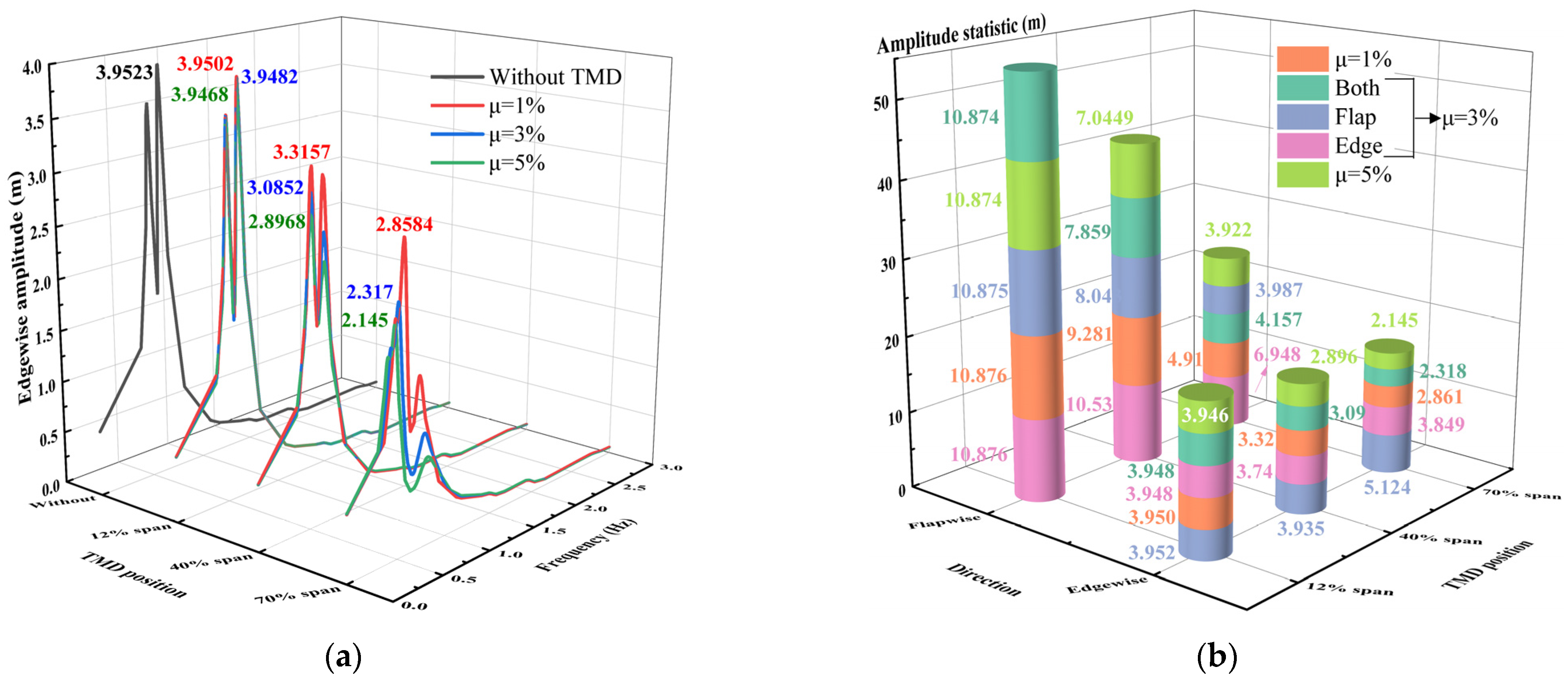
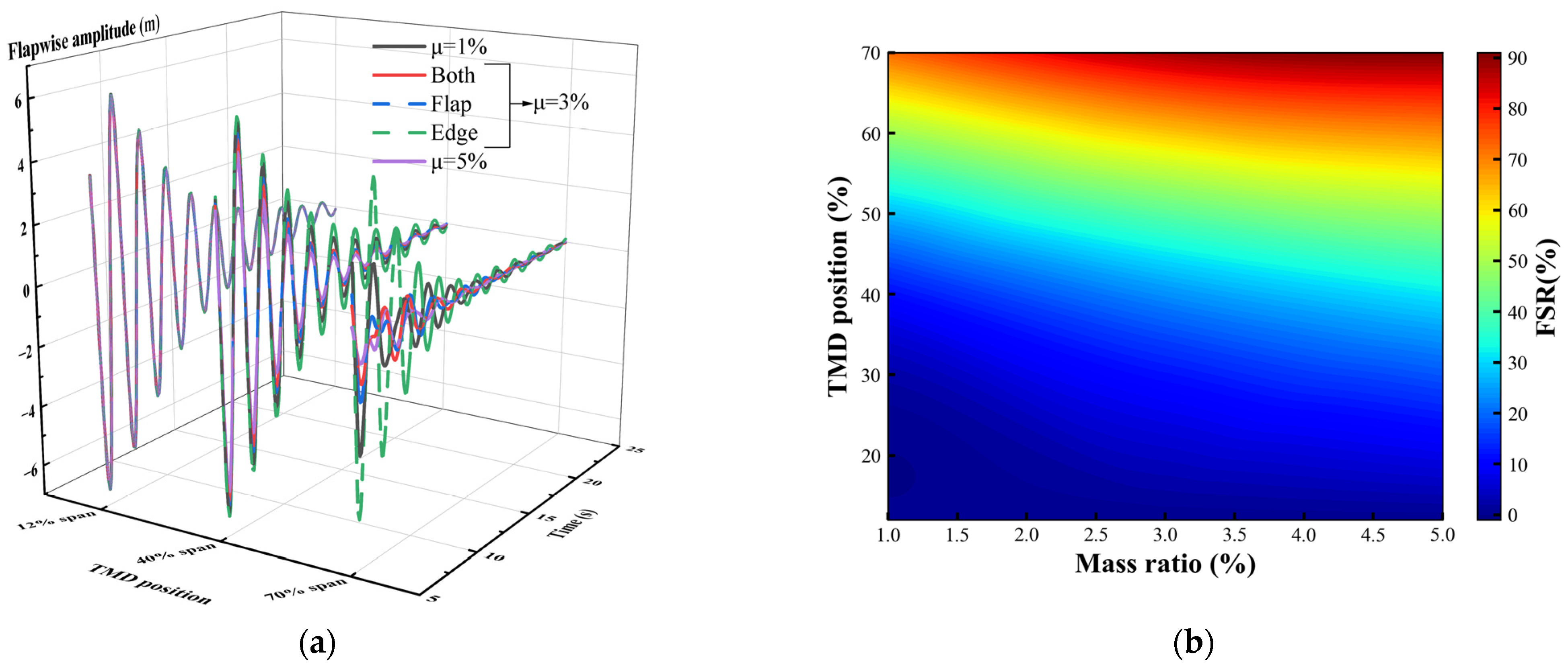
Given the poor performance of both blades with Flap-TMD and those with Edge-TMD under Case 3 loading, special attention was paid to the simulation results of blades with bidirectional TMDs in this regard, as shown in Figure 18a. With bidirectional TMDs, the edgewise vibration amplitudes were consistently lower than those of the original blade, avoiding cases where amplitudes increased. The amplitude response curves with respect to frequency showed that the “dual peaks” were effectively suppressed. As the TMD installation distance increased, amplitude reductions relative to the original blade reached 0.14%, 26.71%, and 45.73% for the 5% mass ratio flutter suppression scheme, with reductions following a nonlinear and accelerating trend.
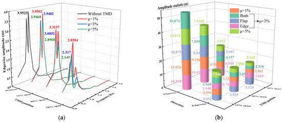
Figure 18.
Tip response of blade with bidirectional TMD under Case 3: (a) blade tip edgewise amplitude; (b) comparison of blade maximum amplitude under different TMD schemes.
Figure 18b presents the statistical results of the maximum blade amplitude responses under different TMD mass ratios and installation positions, including data for both blade with bidirectional and unidirectional TMDs for better comparison. The vertical axis represents vibration amplitude, with lower values indicating better suppression. The results show that the 5% mass ratio bidirectional TMD achieved the greatest amplitude reduction in both the flapwise and edgewise directions, offering the best flutter suppression performance. A 3% mass ratio bidirectional TMD followed, slightly outperformed by the Flap-TMD at the 70% position in flapwise amplitude but demonstrating superior overall performance across other positions and directions.
The limitations of ultra-long flexible blade with unidirectional TMDs are more evident in Figure 18b, showing they achieved good flutter suppression in their action direction but performed poorly in the other degree of freedom, residing at the bottom of the bar chart. This indicates that, under the complex operating conditions of ultra-long flexible blades, unidirectional TMDs result in higher flutter risks, as alternating coupled wind loads are more likely to excite flutter.
Based on the foregoing analysis, the effectiveness and FSR of TMDs in the flapwise and torsional directions were consistent. Similar trends were observed in comparisons involving bidirectional TMDs. Consequently, Figure 19a,b presents the free decay time-domain curves in the flapwise direction and a heatmap of the torsional direction for 15 MW blades with bidirectional TMDs.
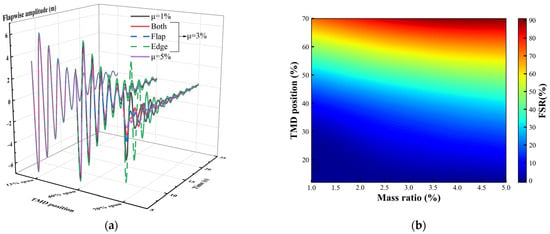
Figure 19.
Blade with bidirectional TMDs’ simulation results under free vibration motion: (a) temporal dynamics of blade tip’s flapwise amplitude; (b) torsional direction FSR.
Figure 19a demonstrates that the free decay motion of the 15 MW blade at the 12% spanwise position is nearly identical across various TMD configurations, indicating that, despite ample movement space near the blade root, the limited spanwise position hinders the effectiveness of TMDs. At the 70% spanwise position, the Edge-TMD exhibits the slowest vibration decay, followed by the 1% mass ratio bidirectional TMD. The 3% mass ratio bidirectional TMD and Flap-TMD show interleaved time-domain curves, while the 5% mass ratio bidirectional TMD achieves the best vibration suppression, consistent with previous findings.
Figure 19b illustrates that the FSR of bidirectional TMDs increases with both higher mass ratios and greater spanwise positions. Notably, the increase in spanwise position has a more pronounced effect on the FSR than the increase in mass ratio. When bidirectional TMDs are installed at the 70% spanwise position of blade, the FSR ranges from 72.55% to 90.79%, effectively mitigating the risk of flutter exacerbation in ultra-long flexible blades.
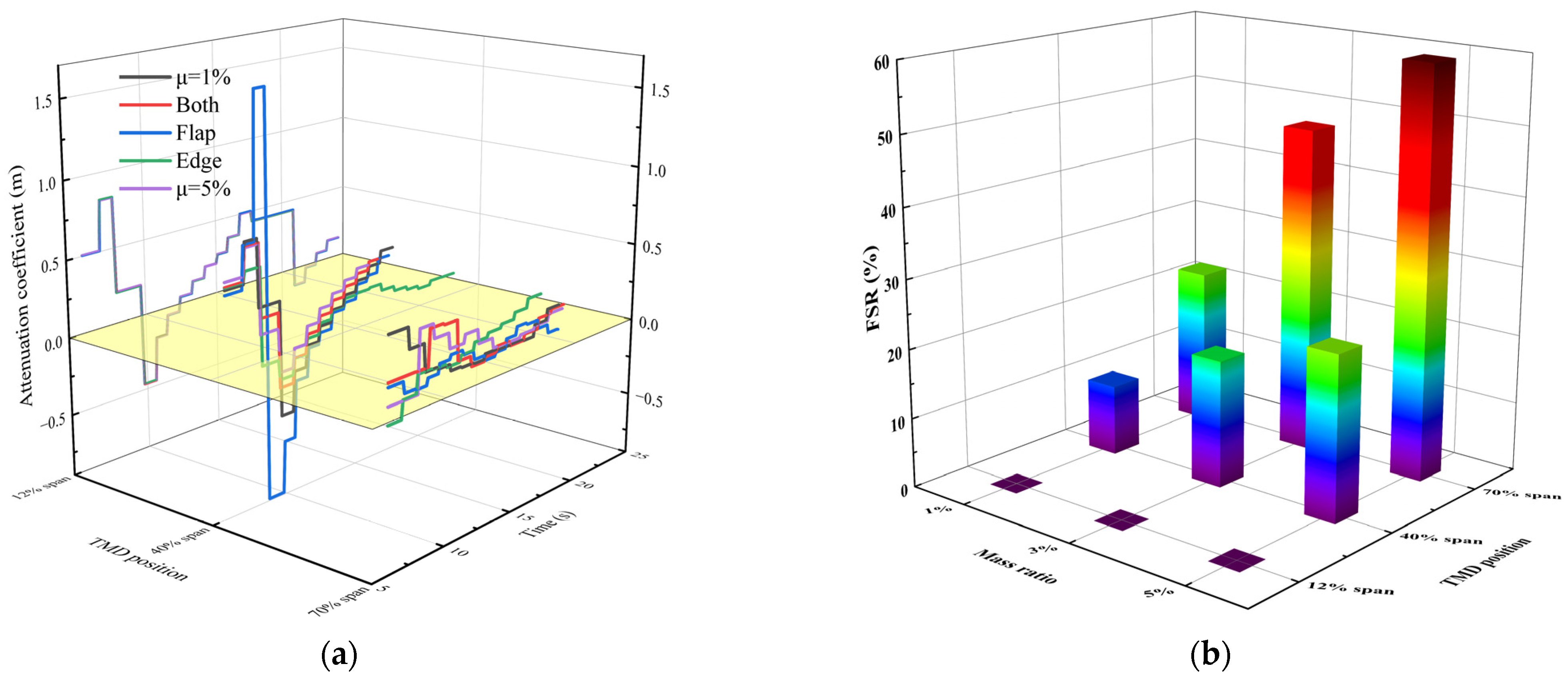
Figure 20a shows that, at the 12% spanwise position, the time-domain curves of the attenuation coefficient in the edgewise direction are nearly identical, corroborating the similarity in blade’s modal deformation and steady-state amplitude statistics under this condition. In comparisons at the 40% spanwise position, the attenuation coefficient of the Flap-TMD exhibits significant fluctuations, but its positive changes result in a higher FSR compared to the edgewise TMD at the same position.
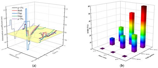
Figure 20.
Blade with bidirectional TMDs’ statistical results under free vibration motion: (a) temporal dynamics of blade’s edgewise attenuation coefficient; (b) edgewise FSR.
Figure 20b indicates that the FSR in the edgewise direction for blades with bidirectional TMDs is consistently positive, with more linear variations with TMD parameters compared to the flapwise and torsional directions, reaching a maximum of 59.39%. For the same mass ratio, the FSR of bidirectional TMDs improves by 106%, 40.9%, and 300% compared to Flap-TMDs, and by 28.8%, 612%, and 375% compared to Edge-TMDs. Unlike unidirectional TMDs, bidirectional TMDs do not exhibit negative FSR, demonstrating their ability to mitigate adverse effects associated with unidirectional TMDs in ultra-long flexible blade applications.
4. Conclusions
To address the complex nonlinear vibration and flutter issues in offshore ultra-large wind turbine blades, flutter suppression research was conducted on 15 MW offshore wind turbine blade with unidirectional and bidirectional TMD. Using a high-fidelity full-scale blade model, the vibration characteristics and flutter responses of ultra-long flexible blades were analyzed, and the influence and mechanisms of unidirectional and bidirectional TMD under various environmental parameters were investigated. The following conclusions were drawn:
1. The nonlinear behavior of ultra-long flexible blades is pronounced, rendering traditional small-deflection assumptions invalid. The R2 values for the first-order modal shapes in the flapwise and edgewise directions are 0.27 and 0.28, respectively, with second-order modal frequency errors as high as 60.5% and 43.2%. Thus, high-fidelity blade FSM are essential for flutter suppression studies. The structural response of ultra-long flexible blades is complex, exhibiting strong coupling between flapwise and torsional motions, with edgewise motion cycles interleaving with flapwise and torsional cycles, leading to frequent energy transfers.
2. After ultra-long and flexible blades with unidirectional TMDs, increasing the spanwise distance significantly improves vibration suppression, but the effect is typically limited to the TMD’s direction of motion. In steady-state vibration analysis, under Case 1, Flap-TMDs reduce flapwise amplitude by up to 58.92% and edgewise amplitude by up to 46.13%; under Case 2, Edge-TMDs reduce flapwise amplitude by up to 33.61% and edgewise amplitude by up to 53.2%, with the effectiveness confined to the TMD’s motion direction.
3. Flutter suppression with unidirectional TMDs in ultra-long flexible blades is not simply linear. In terms of modal shapes, unidirectional TMDs at the 40% spanwise position yield the smallest modal deformation. Under Case 3, while Flap-TMDs effectively reduce the maximum amplitude in the flapwise direction, they increase the amplitude in the edgewise direction at the 70% spanwise position, consistent with free decay motion results. Both Flap-TMD and Edge-TMD at the 70% spanwise position result in negative FSR, indicating no benefit to flutter suppression and challenging conventional understanding. This necessitates careful consideration in the optimization and design of unidirectional TMDs.
4. Considering a blade with a bidirectional TMD, the minimum modal deformations in both flapwise and edgewise directions occur with a 5% mass ratio configuration at the 40% and 70% spanwise positions, respectively, further highlighting the complexity of flutter characteristics in ultra-long flexible blades. Bidirectional TMDs at the 12% spanwise position show modal deformation and steady-state amplitude similar to that of the baseline, unaffected by changes in TMD parameters, consistent with unidirectional TMD behavior. This suggests that, for flutter suppression, the spanwise position of TMDs is more critical than their motion stroke in ultra-long flexible blades.
5. Bidirectional TMDs significantly enhance flutter suppression in ultra-long flexible blades, with suppression effectiveness positively correlated with increasing mass ratios and spanwise distances. In steady-state vibration, bidirectional TMDs further reduce amplitudes in the action direction of unidirectional TMDs and prevent amplitude increases at specific TMD positions. Regarding flutter response, bidirectional TMDs achieve FSR exceeding 90%, consistently avoiding negative FSR and mitigating the risk of flutter in ultra-long flexible blades.
Author Contributions
Conceptualization, M.Z.; Data Curation, T.D. and Y.D.; Formal Analysis, W.L.; Investigation, Y.F.; Project Administration, Y.F.; Resources, J.Y.; Supervision, M.Z.; Validation, W.L.; Visualization, W.L.; Writing—Original Draft, W.L.; Writing—Review and Editing, W.L. All authors have read and agreed to the published version of the manuscript.
Funding
This work was supported by the National Key Research and Development Program of China (Grant No. 2022YFB4201400), Guangdong Science and Technology Department through Guangdong-Hong Kong-Macao Joint Innovation Program (No. 2024A0505040006), Shenzhen Science and Technology Program (KJZD20230923114259049), National Natural Science Foundation of China (52301317), and Guangdong Basic and Applied Basic Research Foundation (2024A1515011587).
Data Availability Statement
The original contributions presented in this study are included in this article. Further inquiries can be directed to the corresponding author.
Conflicts of Interest
Author Jianjun Yang was employed by the company Goldwind Science & Technology Co., Ltd. The remaining authors declare that this research was conducted in the absence of any commercial or financial relationships that could be construed as potential conflicts of interest.
Abbreviations
The following abbreviations are used in this manuscript:
| TMD | Tuned Mass Damper |
| FSR | Flutter Suppression Rate |
| 2-DOF | Two Degrees of Freedom |
| EBM | Equivalent Beam Model |
| FSM | Full-Scale Model |
References
- Sayed, Z. Transforming our world: The 2030 agenda for sustainable development. Ethics Crit. Think. J. 2015, 8, 6. [Google Scholar]
- He, R.; Sun, H.; Gao, X.; Yang, H. Wind tunnel tests for wind turbines: A state-of-the-art review. Renew. Sustain. Energy Rev. 2022, 166, 112675. [Google Scholar] [CrossRef]
- Abdelilah, Y.; Bahar, H.; Criswell, T.; Bojek, P.; Briens, F.; Feuvre, P.L. Renewables 2020: Analysis and Forecast to 2025; IEA: Paris, France, 2020. [Google Scholar]
- Global Wind Energy Council. GWEC|Global Wind Report 2025; Global Wind Energy Council: Brussels, Belgium, 2025; p. 80. [Google Scholar]
- Cozzi, L.; Wanner, B.; Donovan, C.; Toril, A.; Yu, W.; Arsalane, Y.; D’Ambrosio, D.; Liu, J.; Papapanagiotou, S.; Tsoukala, E.; et al. Offshore Wind Outlook 2019: World Energy Outlook Special Report; International Energy Agency: Paris, France, 2019. [Google Scholar]
- European Environment Agency. Harnessing Offshore Wind While Preserving the Seas (EEA Briefing No. 14/2024); Publications Office of the European Union: Luxembourg, 2024. [Google Scholar] [CrossRef]
- Wang, T.; Du, G.; He, J.; Chinese Wind Energy Association (CWEA). International Energy Agency Wind Technology Collaboration Programme. In IEA Wind TCP 2022 Annual Report; IEA: Paris, France, 2023; Available online: https://iea-wind.org/wp-content/uploads/2023/10/CWEA_2022.pdf (accessed on 24 January 2023).
- Zhuang, Y.; Yuan, G. Study on coupled mode flutter parameters of large wind turbine blades. Sci. Rep. 2024, 14, 12804. [Google Scholar] [CrossRef] [PubMed]
- Deng, Y.; Zhu, C.; Zhang, S.Y.; Yang, Y.; Zhang, B. A novel coupling framework for integrating turbine and substructure dynamics of floating offshore wind turbines. Ocean. Eng. 2025, 340, 122307. [Google Scholar] [CrossRef]
- Meehan, P.A. Prediction and suppression of chaos following flutter in wind turbines. Nonlinear Dyn. 2023, 111, 22153–22176. [Google Scholar] [CrossRef]
- Skrzypinski, W.R. Analysis and Modeling of Unsteady Aerodynamics with Application to Wind Turbine Blade Vibration at Standstill Conditions. Ph.D. Thesis, Delhi Technological University, Delhi, India, 2012. [Google Scholar]
- Li, N.; Mu, A.; Yang, H.; Magar, K.T. Optimized under-actuated control of blade vibration system under wind uncertainty. J. Sound Vib. 2020, 467, 115070. [Google Scholar] [CrossRef]
- Zhang, S.Y.; Lin, Z.; Li, D.; Deng, Y.; Zhang, Y.; Wang, Y. Vibration suppression of spar-buoy floating wind turbines using a nonlinear stiffness combined inerter-based absorber. Ocean. Eng. 2025, 329, 121146. [Google Scholar] [CrossRef]
- Liao, W.; Zhang, M.; Yang, J.; Fan, Y.; Deng, Y. Blades Flutter Suppression in Large Wind Turbines: A Review. Acta Energiae Solaris Sin. 2025, 46, 556–566. [Google Scholar]
- Basu, B.; Zhang, Z.; Nielsen, S.R. Damping of edgewise vibration in wind turbine blades by means of circular liquid dampers. Wind Energy 2016, 19, 213–226. [Google Scholar] [CrossRef]
- Zhang, Z.; Fitzgerald, B. Tuned mass-damper-inerter (TMDI) for suppressing edgewise vibrations of wind turbine blades. Eng. Struct. 2020, 221, 110928. [Google Scholar] [CrossRef]
- Li, W.; Yan, S.; Li, G.; Du, Y. Mitigation of In-Plane Vibrations in Large-Scale Wind Turbine Blades with a Track Tuned Mass Damper. Struct. Control. Health Monit. 2023, 2023, 8645831. [Google Scholar] [CrossRef]
- Gaertner, E.; Rinker, J.; Sethuraman, L.; Zahle, F.; Anderson, B.; Barter, G.E.; Abbas, N.; Meng, F.; Bortolotti, P.; Skrzypiński, W.; et al. IEA Wind TCP Task 37: Definition of the IEA 15-Megawatt Offshore Reference Wind Turbine; National Renewable Energy Lab. (NREL): Golden, CO, USA, 2020. [Google Scholar]
- Chen, J.B.; Li, J. Dynamic response and reliability analysis of non-linear stochastic structures. Probabilistic Eng. Mech. 2005, 20, 33–44. [Google Scholar] [CrossRef]
- Thomson, W. Theory of Vibration with Applications; CrC Press: Boca Raton, FL, USA, 2018. [Google Scholar]
- Hoang, N.; Fujino, Y.; Warnitchai, P. Optimal tuned mass damper for seismic applications and practical design formulas. Eng. Struct. 2008, 30, 707–715. [Google Scholar] [CrossRef]
- Yang, F.; Sedaghati, R.; Esmailzadeh, E. Vibration suppression of structures using tuned mass damper technology: A state-of-the-art review. J. Vib. Control. 2022, 28, 812–836. [Google Scholar] [CrossRef]
- Den Hartog, J.P. Mechanical Vibrations; Courier Corporation: North Chelmsford, MA, USA, 1985. [Google Scholar]
- IEC 61400-23:2014; Wind Turbines—Part 23: Full-Scale Structural Testing of Rotor Blades. International Electrotechnical Commission: Geneva, Switzerland, 2014.
- Germanischer Lloyd. Rules and Guidelines IV Industrial Services 1 Guideline for the Certification of Wind Turbines; Germanischer Lloyd: Hamburg, Germany, 2010. [Google Scholar]
- Germanischer Lloyd. Rules and Guidelines IV Industrial Services 2 Guideline for the Certification of Offshore Wind Turbines; Germanischer Lloyd: Hamburg, Germany, 2012. [Google Scholar]
- Al-Khudairi, O.; Hadavinia, H.; Little, C.; Gillmore, G.; Greaves, P.; Dyer, K. Full-scale fatigue testing of a wind turbine blade in flapwise direction and examining the effect of crack propagation on the blade performance. Materials 2017, 10, 1152. [Google Scholar] [CrossRef] [PubMed]
- Lee, H.G.; Lee, J. Measurement theory of test bending moments for resonance-type fatigue testing of a full-scale wind turbine blade. Compos. Struct. 2018, 200, 306–312. [Google Scholar] [CrossRef]
- Zhou, A.; Shi, J.; Dong, T.; Li, J.; Zhu, Y.; Xu, X. Characteristics evaluation of TFTs method for fatigue testing of ultra-large offshore wind turbine blade. Eng. Fail. Anal. 2025, 170, 109240. [Google Scholar] [CrossRef]
- Lee, H.G.; Park, J. Static test until structural collapse after fatigue testing of a full-scale wind turbine blade. Compos. Struct. 2016, 136, 251–257. [Google Scholar] [CrossRef]
- Liao, G.; Liao, S.; Hong, Z.; Zhang, Z. On-line damage assessment of wind turbine blade full-size structural fatigue testing. In Journal of Physics: Conference Series; IOP Publishing: Bristol, England, 2022; Volume 2310, p. 012049. [Google Scholar]
- Zhou, A.; Shi, J.; Dong, T.; Ma, Y.; Weng, Z. Nonlinear vibration characteristics of virtual mass systems for wind turbine blade fatigue testing. Wind Energy Sci. 2024, 9, 49–64. [Google Scholar] [CrossRef]
Disclaimer/Publisher’s Note: The statements, opinions and data contained in all publications are solely those of the individual author(s) and contributor(s) and not of MDPI and/or the editor(s). MDPI and/or the editor(s) disclaim responsibility for any injury to people or property resulting from any ideas, methods, instructions or products referred to in the content. |
© 2025 by the authors. Licensee MDPI, Basel, Switzerland. This article is an open access article distributed under the terms and conditions of the Creative Commons Attribution (CC BY) license (https://creativecommons.org/licenses/by/4.0/).

