Article

Experimental and Numerical Model Investigations of the Underwater Towing of a Subsea Module

1
College of Shipbuilding Engineering, Harbin Engineering University, Harbin 150001, China
2
Offshore Oil Engineering Co., Ltd., Tianjin 300451, China
*
Author to whom correspondence should be addressed.
J. Mar. Sci. Eng. 2019, 7(11), 384; https://doi.org/10.3390/jmse7110384
Submission received: 26 September 2019 / Revised: 18 October 2019 / Accepted: 23 October 2019 / Published: 29 October 2019

Abstract

:
In underwater towing operations, the drag force and vertical offset angle of towropes are important considerations when choosing and setting up towing equipment. The aim of this paper is to study the variation in drag force, vertical offset angle, resistance, and attitude for towing operations with a view to optimizing these operations. An underwater experiment was conducted using a 1:8 scale physical model of a subsea module. A comprehensive series of viscous Computational Fluid Dynamics (CFD) simulations were carried out based on Reynolds-averaged Navier–Stokes equations for uniform velocity towing. The results of the simulation were compared with experimental data and showed good agreement. Numerical results of the vorticity field and streamlines at the towing speeds were presented to analyze the distribution of vortexes and flow patterns. The resistance components were analyzed based on the numerical result. It was found that the lateral direction was a better direction for towing operations because of the smaller drag force, resistance, and offset angle. Similar patterns and locations of streamlines and vortexes were present in both the longitudinal and lateral directions, the total resistance coefficient decreases at a Reynolds number greater than that of a cylinder.

1. Introduction

The oil and gas industry are engaging in offshore operations in deeper and more distant areas. As a result, subsea modules are becoming larger and more complex [1,2,3]. A key issue is how to transport subsea modules with the lowest risk and cost. Most approaches to addressing these issues can be divided into two categories: (1) the subsea module can be transported on the deck of a vessel and lowered through the surface near the subsea module site, and (2) in wet tow methods, the module can be lowered through the splash zone at inshore sheltered areas and towed on the surface of the water or underwater [4]. When the body is towed on the surface, the floating state, stability, and drag force of the towed body should meet the requirements of the towing operation and take into account the effects of wind and waves. The platform is one of the most commonly towed bodies, and excessive roll and pitch motions in stormy seas can lead to damage to the structure and to the overturning of the platform. For bodies with a large height, the wind load is also an important factor. The towed body can be linked to the vessels either directly by towropes or indirectly by pencil buoys when it is towed underwater [5]. The underwater towing method is used in marine exploration to obtain high-resolution seismic images of the subsurface, including shallow sediments in a deep-sea environment [6]. Unlike the surface towing method, the body is totally underwater and away from the surface, hence the wave and wind loads are no longer significant parameters. Subsea towing does not require vessels with large decks and high lifting capacity and avoids the effects of working in extreme sea states [7].
In recent years, several studies on towing operations have been carried out using numerical or experimental methods. Kang et al. [8] analyzed a specific jack-up model during surface towing by considering the roll, pitch, and heave motions in a stochastic wave input process. They created a reliability-based stochastic analysis method and considered the probability of deck overtopping and instability for roll and pitch. Zhang et al. [9] studied the surface towing dynamic behaviors of an offshore integrated meteorological mast (OIMM) with different towing conditions in various wind and wave conditions using MOSES software developed by Ultramarine. The OIMM with a low draft had the most significant pitch motion fluctuations because of the small righting force, but heave motion showed increases in middle draft states. Ding et al. [10] found that higher mooring positions and towing velocities can achieve moderate dynamic response amplitudes. Their results also showed that the wind load is dominant when the drag force of the towed body is small and that the drag resistance fluctuates greatly because of the influence of the free surface. In the underwater towing method, the drag force is an important parameter in towing operations. Rattanasiri et al. [11] investigated the viscous interaction between autonomous underwater vehicles (AUVs) and studied the influence of their shape using ANSYS CFX 12.1 software, and found that the spacing between hulls determines the drag force of AUVs, and that increasing the spacing results in a lower interaction. The configuration’s shape had no positive effect on the drag force for the fleet. Wu et al. [12] designed a controllable underwater towing system and examined the hydrodynamic and control behaviors using towing experiments and the Charge Coupled Device (CCD) underwater photogrammetric technique. Go and Ahn [13] proposed a method for determining hydrodynamic coefficients by using the Computational Fluid Dynamics (CFD) method to simulate the working conditions of a towed-fish. The hydrodynamic model obtained can be used to simulate the motion of a towed-fish. Due to the effect on the stability of the towed body, the hydrodynamic performance and shape variation in the towrope should be considered in the towing system. Sun et al. [14] carried out a new nodal position finite element method to avoid the accumulated errors from time steps over a long-time simulation, and used the new method for towing simulations. To improve the stability of the towed vehicle, a two-part underwater towing method has been developed experimentally and numerically [15,16]. It is preferable to select a sufficiently long secondary cable to improve the hydrodynamic behavior of the towed vehicle for heave and pitch motions [17]. The vertical offset angle of the towrope is limited by the size of the moon-pool, or by heave compensation equipment in subsea towing, and thus the vertical offset angle of the towrope is an important factor to be considered, in addition to the drag force. Jacobsen and Leira [18] investigated the variation in dynamic drag force and offset angle for towropes in different wave and heave periods using both towing experiments and software simulation of marine operations (SIMO) developed by Det Norske Veritas. They also studied the influence of the bottom proximity effects of the added mass.
The aforementioned research provides a description of towing methods, including surface towing and subsea towing. There are two important parameters in the subsea towing method: the drag force and the vertical offset angle of towropes. To study the hydrodynamic performance and characteristics of a subsea module, a subsea towing analysis should be conducted. Different towing directions matched with different towing speeds can form different towing cases. Studies should be carried out to determine which case is better for underwater towing of this subsea module, and to explain why this is so. This involves studying how the towing conditions affect the drag force and offset angle. In the present study, numerical results of the vorticity field and streamlines at different towing speeds were presented to analyze the distribution of vortexes and flow patterns and to explain the effects of drag force, offset angle, and resistance coefficients. The main objective of the present study is to analyze the drag force, vertical offset angle, attitude of the module, and flow characteristics for uniform towing motions using physical towing experiments and numerical simulations (STAR-CCM+ 13.04).
The paper is organized as follows: first, module configuration and towing tests in a calm water are described, and the experimental results of drag force coefficients, vertical offset angle, and the attitude of the module are presented. A brief description of the numerical method used is then presented, followed by a description of the numerical model setup, mesh generation, and validation of the numerical results. Subsequently, the relationships between the drag force coefficients, vertical offset angle, and towing velocities are analyzed. Results of the flow characteristic studies based on the numerical analysis are then presented. In the last section, the components of resistance were analyzed, and the frictional and pressure resistance coefficients were obtained.

2. Tests Using a Physical Model

2.1. Geometry and General Parameters

The model of the subsea module is shown in Figure 1. The subsea module was designed by Offshore Oil Engineering Co., Ltd. for the subsea pipeline from the Wenchang gas fields to the Yacheng pipeline. The data presented in this paper have been rescaled according to Froude’s similarity law with a scale ratio λ m = 8 . The test model is made of Q235 carbon steel. The model consisted of a set of intersecting steel pipes that were welded together between two trusses, with plates that were divided into three parts and welded below the trusses. The trusses were made using a universal beam, using H300A steel for the upper trusses and H300B for the lower ones. Three types of steel pipes were used: φ 273 × 13 , φ 168 × 9 , and φ 140 × 8 . The steel pipes were welded at the inner panel point. The lower truss and perforated plate create a large amount of rectangular space. In accordance with actual construction requirements, it was necessary to punch in each rectangular space. As shown in Figure 2, the diameter of each drain hole on the lowest surface plate was φ = 6.250 mm. Three perforated plates were enclosed by skirt plates and form a large rectangular cavity under the perforated plate. The thickness of the perforated plate and skirt is 94 mm. The model was 2.210 m long (L), 1.500m wide (B), and 0.440 m deep (H), and its total weight was 104 kg. The submerged weight is 852 N. In this experiment, the Reynolds number Re = 3.78 × 10⁵ > 3.5 × 10⁵.

2.2. Experimental Setup

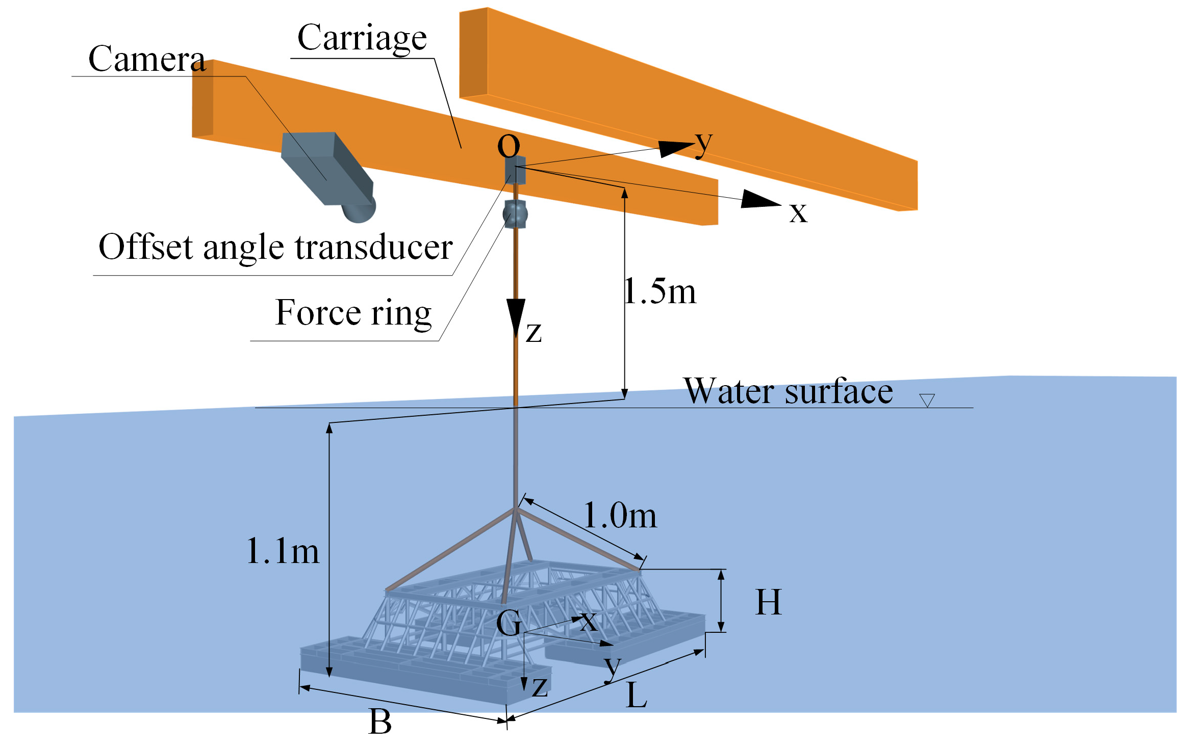
The model tests were conducted in the towing tank at Harbin Engineering University. The tank is 110 m long, 7 m wide, and 3.5 m deep, and the water temperature was 14 °C. The vertical position of the center of gravity from the bottom was 0.191 m and the horizontal position from the head was 1.105 m. The arrangement of the experimental equipment, north-east-down coordinate system (O-xyz), and the coordinate system of gravity (G-xyz) are shown in Figure 3. The Ox axis is along the longitudinal of the water tank, O is the location of the spin center, and G is the center of gravity. An offset angle transducer was fixed on the carriage and was connected to the main towrope with a force ring. The offset angle transducer can only measure the angle of the main towrope about the Oy axis, the range of measurement is ± 20°, and the accuracy is 0.01°. The model was suspended from the force ring through four branches, each 10 mm thick. The branches of the towropes were linked to four points equidistant from the center of gravity on the frame. The coordinates of the four points were (0.760, 0.440, −0.249) m, (0.760, −0.440, −0.249) m, (−0.760, −0.440, −0.249) m, and (−0.760, 0.440, −0.249) m. The model was underwater at all times. The force ring used in this experiment was an elastic force sensor. When the force sensor was stretched or compressed axially, the force signal was converted into a voltage signal, and the numerical value was output by the data acquisition system. The force sensor has a measuring voltage of 5 V, a measuring range of 10,000 N, and an accuracy of 1 N. A camera was used to record the attitude of the model. The camera is installed on the carriage in the third octant of the initial position of G-xyz.
To precisely investigate the variation of drag force and offset angle with velocities, each case was applied twice. The test conditions are shown in Table 1. The longitudinal (Gx) direction of the model was along the lengthwise direction of the water tank (Ox) and stable before the X-direction cases. The lateral (Gy) of the model direction was along the lengthwise direction of the water tank (Ox) and stable before the Y-direction cases. The data for the force ring were cleared before each case, and thus the wet weight was excluded.

2.3. Physical Modeling of the Module

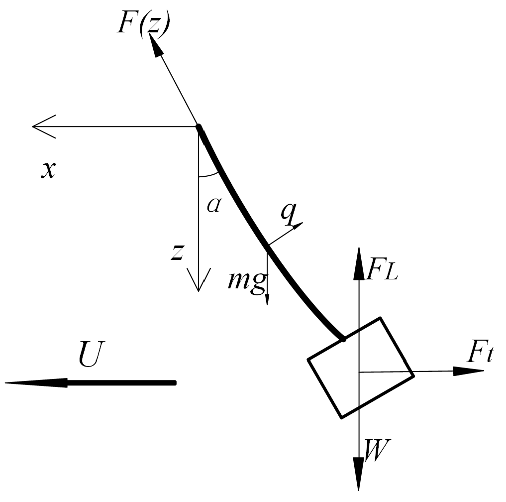
The force analysis of an object with a submerged weight W suspended by a wire is shown in Figure 4. At any vertical position z of the wire, the system satisfied the following equilibrium function in the Oz direction, with a towing speed of U :
F ( z ) cos α = W F L + ρ g a z + m g l ( z ) 0 l ( z ) q sin α d s
where F ( z ) is the drag force at the end of the wire, q and m g are the drag force and submerged weight per unit length, respectively, α is the offset angle, a is the cross-sectional area of wire with a length of l ( z ) , and F L indicates lift force. In the Ox direction, the equilibrium function is
F ( z ) sin α = F t + 0 l ( z ) q cos α d s p 0 ( z ) sin α
The first term is total resistance (frictional resistance F f and pressure resistance F p v ). The second term is the horizontal component of the drag force acting on the wire and p 0 ( z ) is the pressure at level z.
Equations (1) and (2) can be approximated and simplified to (3) and (4). The length of wire is small and its hydrodynamic force has little effect when compared with the drag force and weight of the module. Thus, the weight and drag force of the wire can be ignored.
F ( z ) cos α = W F L
( F ( z ) + p 0 ( z ) a ) sin α = F t

2.4. Experimental Results

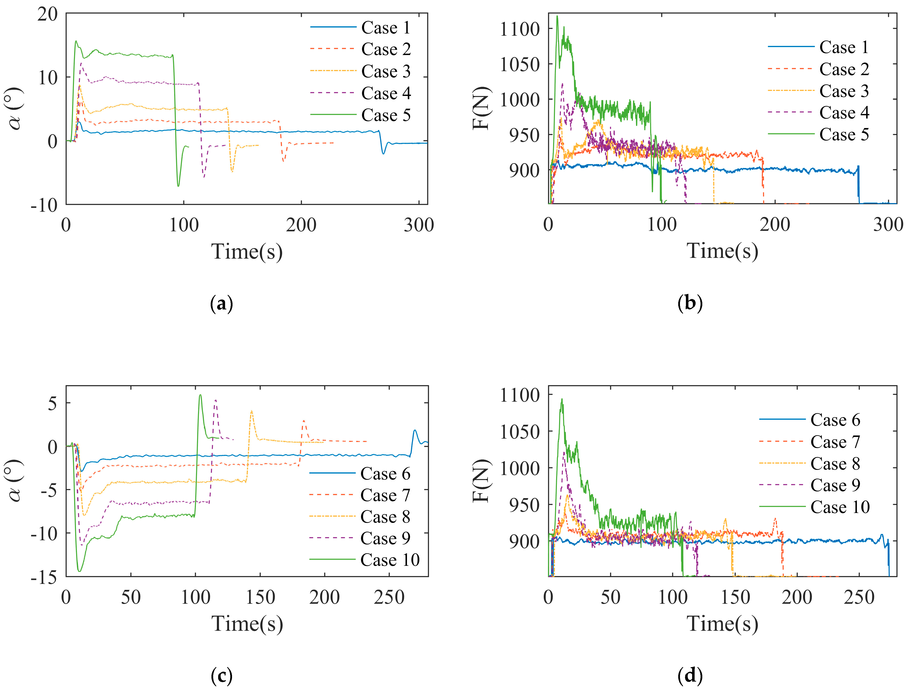
In this section, the drag force and offset angle are analyzed considering the submerged weight of the module. The data obtained from the two cases in the same state were in good agreement with each other. As shown in Figure 5a,b, the drag force ( F X , E X P ) and the offset angle ( α X , E X P ) in the X-direction tow increased rapidly as the model accelerated and reached a maximum, F X , E X P and α X , E X P then decreased slowly. The maximum drag force increased as the towing velocities increased, but the maximum in Case 1 was not obvious. There was a peak after the maximum in Cases 2, 3, 4, and 5, and the peak value also increased as the velocities increased. Finally, F X , E X P and α X , E X P reduced with the model acceleration until stable. After considering the submerged weight of the module, the maximum drag forces in the X and Y directions increased nonlinearly with the towing speed, and the values were very similar. The maximum relative difference was 8.6%. This occurred when the drag speed was 0.4 m/s. The maximum drag force of 1119.037 N occurred when the speed was 0.6 m/s in the X-direction. The maximum drag force was 131.3% of the submerged weight, while the minimum drag force of 917.615 N occurred at a speed of 0.2 m/s, also in the X-direction, and was 107.7% of the submerged weight. The average drag force for a uniform state in the X-direction increased noticeably at two-speed ranges: 0.2 m/s–0.3 m/s and 0.5 m/s–0.6 m/s, and the maximum rate of increase was 66.1%. The minimum rate of increase was 7.4% and appeared in the speed range of 0.3 m/s–0.5 m/s. The average drag force in the Y-direction showed a different trend: a peak occurred at a speed of 0.3 m/s with a value of 908.026 N, while the drag force increased nonlinearly after 0.4 m/s. The model was affected by vortex-induced oscillation, and hence the measurements, especially for drag force, are oscillating when the model is towed in a uniform motion. The amplitude of oscillation increased with increased velocities. The maximum oscillation rate was 6.45% and appeared in Case 3. The maximum change in the drag force was 3.662 N and appeared in Case 5. Vortex-induced vibration had little effect on the offset angle. The maximum relative fluctuation rate was 1.28% and appeared in Case 1. The maximum vertical deflection angle was 0.0977° and occurred in Case 5.
Figure 5c,d shows time series results from the experiments for the drag force ( F Y , E X P ) and offset angle ( α Y , E X P ) in the Y-direction tow. Compared with the X-direction tow, the maximum F Y , E X P value is close to maximum F X , E X P , and their maximum difference is 8.6%, which occurred when the velocity was 0.4 m/s. F Y , E X P and α Y , E X P still have oscillations under stable towing, but F Y , E X P and α Y , E X P are closed under different velocities. The values of α Y , E X P show different trends to those of as α X , E X P : the values of α Y , E X P stop reducing for a period of time in Cases 8, 9, and 10. In this paper, stable towing means that the drag force and offset angle of the module vary within a certain range. The maximum oscillation rate was 59.8% and appeared in Case 3, and the maximum change in drag force was 29.908 N. The maximum relative fluctuation rate of 1.77% appeared in Case 1, and the maximum vertical deflection angle was 0.0488°. The maximum offset angle for all towing tests appeared at the speed of 0.6 m/s for α X , m a x , E X P = 15.879°. The minimum offset angle appeared at the same speed for α Y , m a x , E X P = 2.863°. The maximum difference between maximum offset angles ( α X , m a x , E X P and α Y , m a x , E X P ) was 14.5%, and the minimum was 1.0%.
When the carriage stopped, the offset angle decreased at first, and then increased to the peak value in the opposite direction. The drag force appeared as another peak and finally decreased rapidly. These phenomena occurred because the carriage stopped with a large acceleration in a short time. In the X-direction towing cases, these peak values were greater than the average offset angle in Cases 1 and 2, and the maximum rate was 142.6%. These peak values were less than the average offset angle in Cases 3, 4, and 5, and the maximum rate was 88.3%. Except for Cases 1 and 2, the drag forces do not show peak value as the offset angles, they only decrease rapidly when the carriage stops because the oscillation is greater. The peak values were 100.4% and 101.1% of the average drag forces in Cases 1 and 2, respectively. In the Y-direction cases, the peak values of the offset angle in the stopping state were greater than the peaks in the X-direction and the average values in the Y-direction. The maximum difference of the peaks in the X and Y-directions was 100.4% at a speed of 0.6 m/s, and the minimum difference was 38.4% at a speed of 0.2 m/s. As for the drag force, peak values occurred in Cases 6, 7, and 8. The peak values were 100.9%, 102.4%, and 101.3% of the average values, respectively. It can, therefore, be concluded that the drag force and offset angle in the Y-direction were more easily affected by centripetal forces in the stopping state.
The relationship between the average drag coefficient ( C d ), the average drag force ( F ), the wetted area ( A ), and drag velocity ( U ) is given by [19]:
C d = 2 F ρ A U 2
where ρ is the density of water. The module is too irregular to be treated as a cylinder and has a large scale like that of a ship. Consequently, the wetted area was selected as a non-dimensional parameter where A = 17.290 m2.
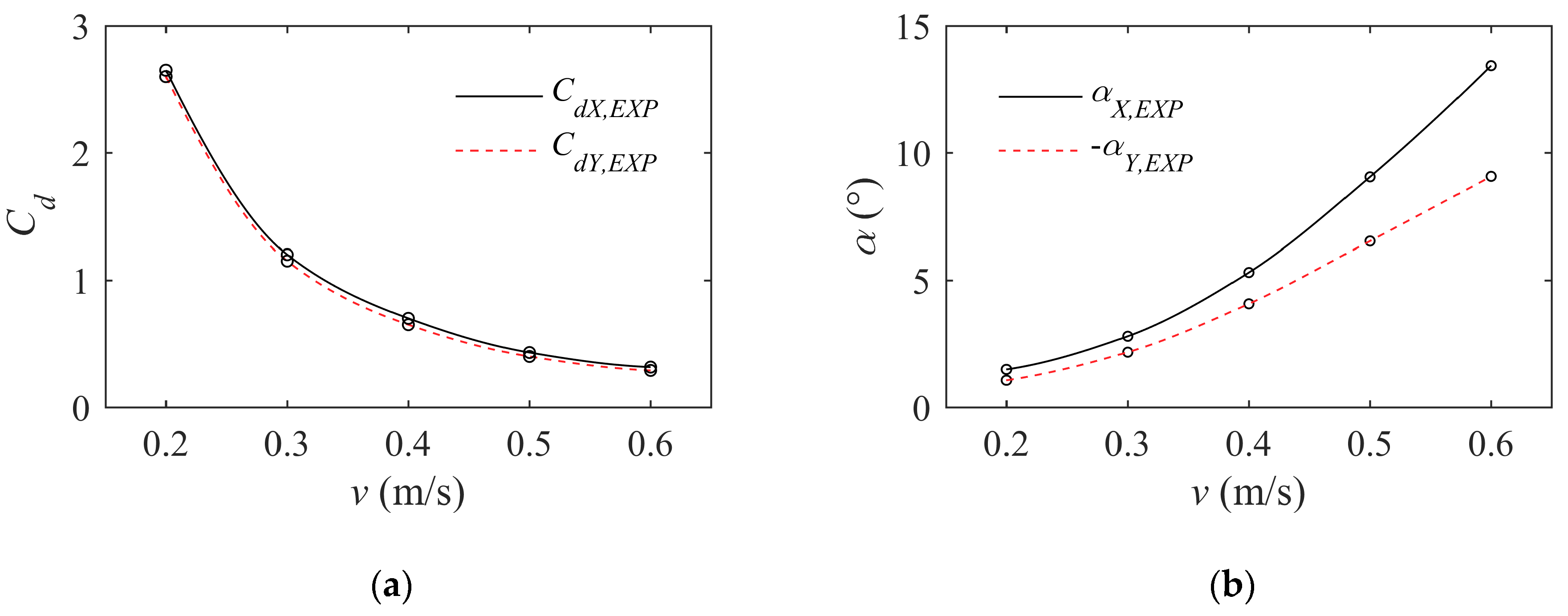
The comparisons of variation in the average drag coefficient and offset angle with velocity in different towing directions are shown in Table 2 and Figure 6. The average drag force was calculated from the average of F Y , E X P and F X , E X P in a stable towing state. As illustrated in Table 2, the drag coefficients decrease with velocity, and they change little in high-velocity states. The maximum average drag coefficients occurred at a speed of 0.2 m/s ( C d X , E X P = 2.607 and C d Y , E X P = 2.603) and the minimum coefficients occurred at a speed of 0.6 m/s (0.316 and 0.299). The average drag force coefficients C d X , E X P and C d Y , E X P are very similar but C d X , E X P is larger than C d Y , E X P for the same towing speed. The maximum difference between C d X , E X P and C d Y , E X P was only 5.4% at the speed of 0.6 m/s. The reason for this difference is that the resistance in the X-direction is greater than in the Y-direction, especially for pressure resistance. A more detailed discussion is provided in Section 4.4.
The vertical offset angle increased with velocity, the average offset angle in the X-direction towing shows a clear non-linear variation, but the maximum offset angle shows an almost linear increase. In stable towing states, the maximum average offset angle α X , E X P = 13.430° at 0.6 m/s, and the minimum offset angle α Y , E X P = 1.063° at 0.2 m/s. The maximum difference between the average offset angles in the X and Y-direction tests ( α X , E X P and α Y , E X P ) was 32.4%, and the minimum was 22.4%. As shown in Figure 6, the difference in the drag force coefficients was very small. However, there was an obvious difference between offset angles in the X and Y-direction and α Y , E X P was less than α X , E X P . Thus Y-direction towing could be a better choice if the offset angle limit is more important for towing operations, especially for high speed towing.
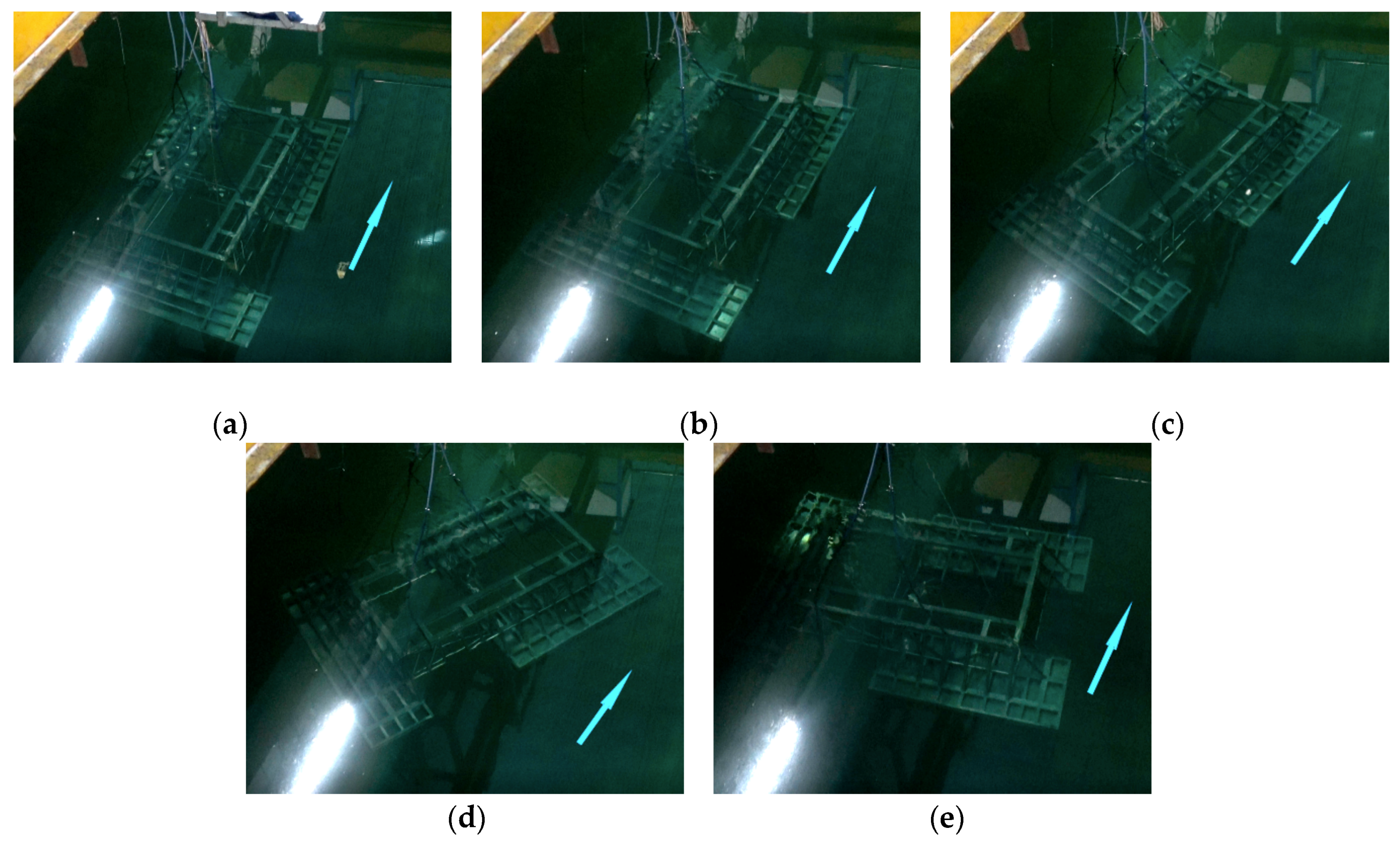
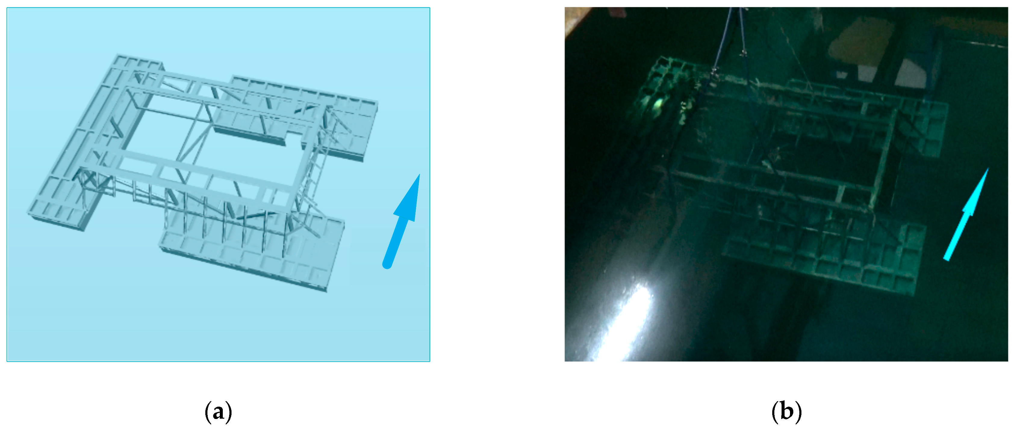
Figure 7 shows a series of images of the attitude of the model at different times when the speed is 0.4 m/s. Other cases show the same phenomenon. The blue arrow indicates the towing direction. In Figure 7a, it can be seen that the longitudinal of the model is parallel with the velocity, and at this time the offset angle is the largest. As shown in Figure 7b, the model starts to rotate when the offset angle decreases. Then, as shown in Figure 7c,d, the model clearly starts yaw motion, and the drag force and offset angle gradually stabilize. Finally, the model maintains the attitude as shown in Figure 7e: the longitudinal is almost vertical to the towing direction, and the heading angle changes repeatedly over a small range. Due to the asymmetry in the model shape, in the transition from acceleration to stable towing, the point of application of fluid forces moves with the fluctuation of the towing velocity and the change of the attitude. This forms an unbalanced hydrodynamic force that makes the heading angle of the model unstable. Finally, the heading angle of the model changes until the hydrodynamic force is symmetrically distributed again, and the model is stable and moves forward with an almost fixed heading angle.

3. Numerical Simulations

To verify the experimental results presented above, a series of CFD simulations, with both X-direction and Y-direction towing were carried out. Furthermore, a detailed study of the flow field was made to reconstruct the vortex patterns. In this section, details of the numerical setup are provided using the X-direction towing test as an example.

3.1. Mathematical and Numerical Models

Each case was simulated using the Reynolds-Average Navier-Stokes equation (RANS) method. Numerical simulations used the CFD software STAR-CCM+ 13.04, developed by SIEMENS in Berlin, Germany. The governing equation was modeled using RANS [20]:
ρ t + ( ρ   v ¯ ) = 0
t ( ρ   v ¯ ) + ( ρ   v ¯   v ¯ ) =   p ¯ I + ( T + T t ) + f b
where ρ is the fluid density, v ¯ and p ¯ are the mean velocity and pressure, respectively, I is the identity tensor, T is the viscous stress tensor, f b is the resultant of the body force, and T t is Reynolds stress tensor.
The finite volume method was employed to discretize the governing equations with the Segregated Flow Solver. The RANS equation was solved using the Semi-Implicit Method for Pressure Linked Equations (SIMPLE) pressure-velocity coupling algorithms to decouple pressure and velocity. To provide closure of the governing equations, the Eddy viscosity model was introduced to the model in terms of the mean flow quantities. The k - ε model was chosen. This is a two-equation model that solves transport equations for the turbulent kinetic energy k and the turbulent dissipation rate ε to determine the turbulent eddy viscosity. The specified equations are described as follows:
t ( ρ k ) + ( ρ k v ¯ ) = [ ( μ + μ t σ k ) k ] + P k ρ ( ε ε 0 ) + S k
t ( ρ ε ) + ( ρ ε v ¯ ) = [ ( μ + μ t σ ε ) ] + 1 T e C ε 1 P ε C ε 2 f 2 ρ ( ε T e ε 0 T 0 ) + S ε
where μ is the dynamic viscosity, and σ k , σ ε , C ε 1 , and C ε 2 are model coefficients. P ε and P k represent production terms. The damping function is represented by f 2 , while S k and S ε are user-specified source terms. The larger-eddy time-scale T e = k / ε . The relationship between the specific time-scale T 0 , the model coefficient C t , the kinematic viscosity ν , and the ambient turbulence value ε 0 is defined by:
T 0 = m a x ( k 0 ε 0 , C t ν ε 0 )
The RANS method and k - ε model have been successfully used in ocean engineering and provide a good compromise between robustness, computational cost, and accuracy [21].
The force on the surface along direction vector n f is computed as:
F = f ( f f p r e s s u r e + f f s h e a r ) n f
where f f p r e s s u r e and f f s h e a r are the pressure and shear force vectors, respectively, on the surface face f . The pressure force vector f f p r e s s u r e along direction vector a f on the surface face f is related to the face static pressure p f and the reference pressure p r e f according to:
f f p r e s s u r e = ( p f p r e f ) a f
The sheer force vector on the surface face f is computed as:
f f s h e a r = T f a f

3.2. Boundary Conditions

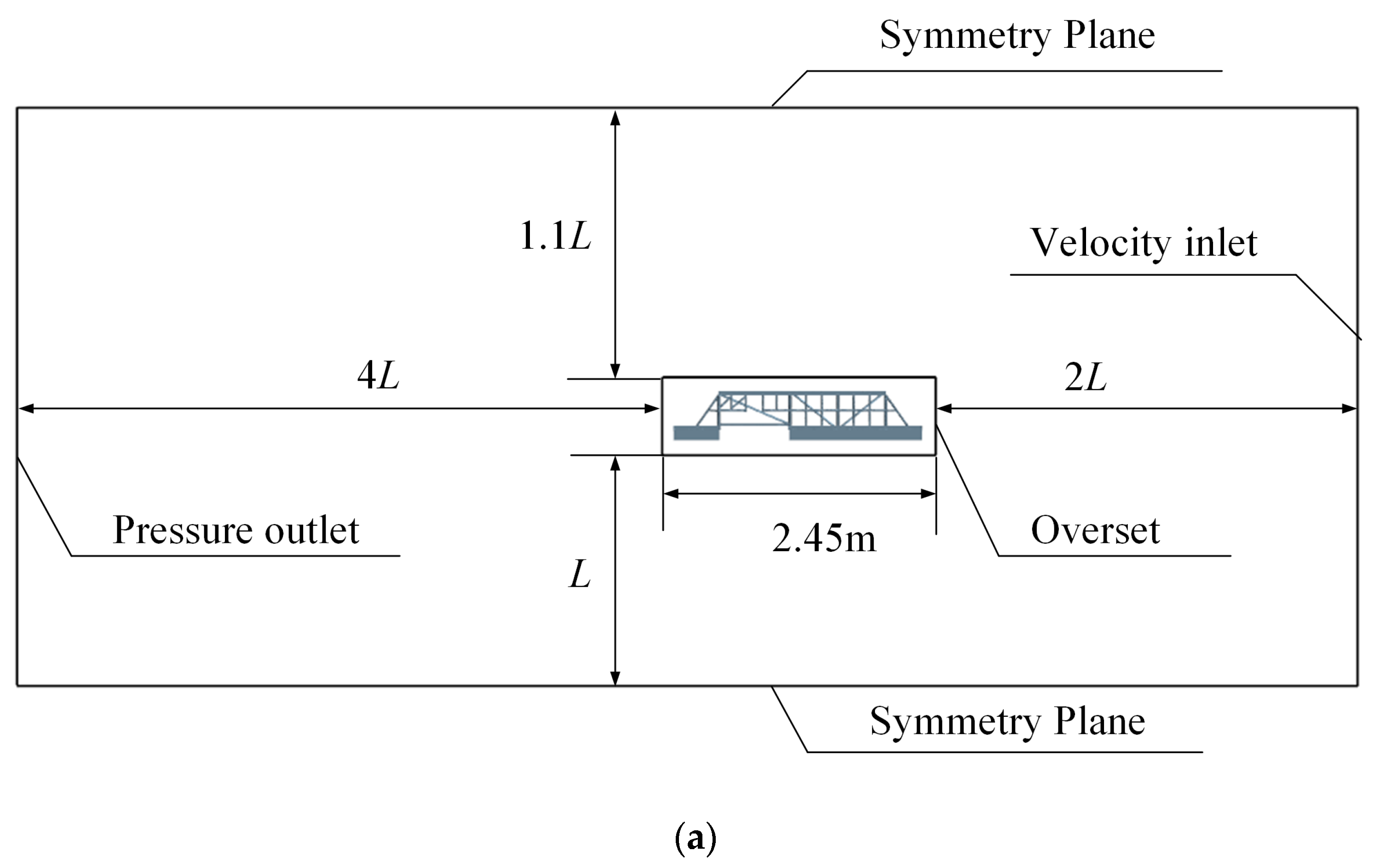
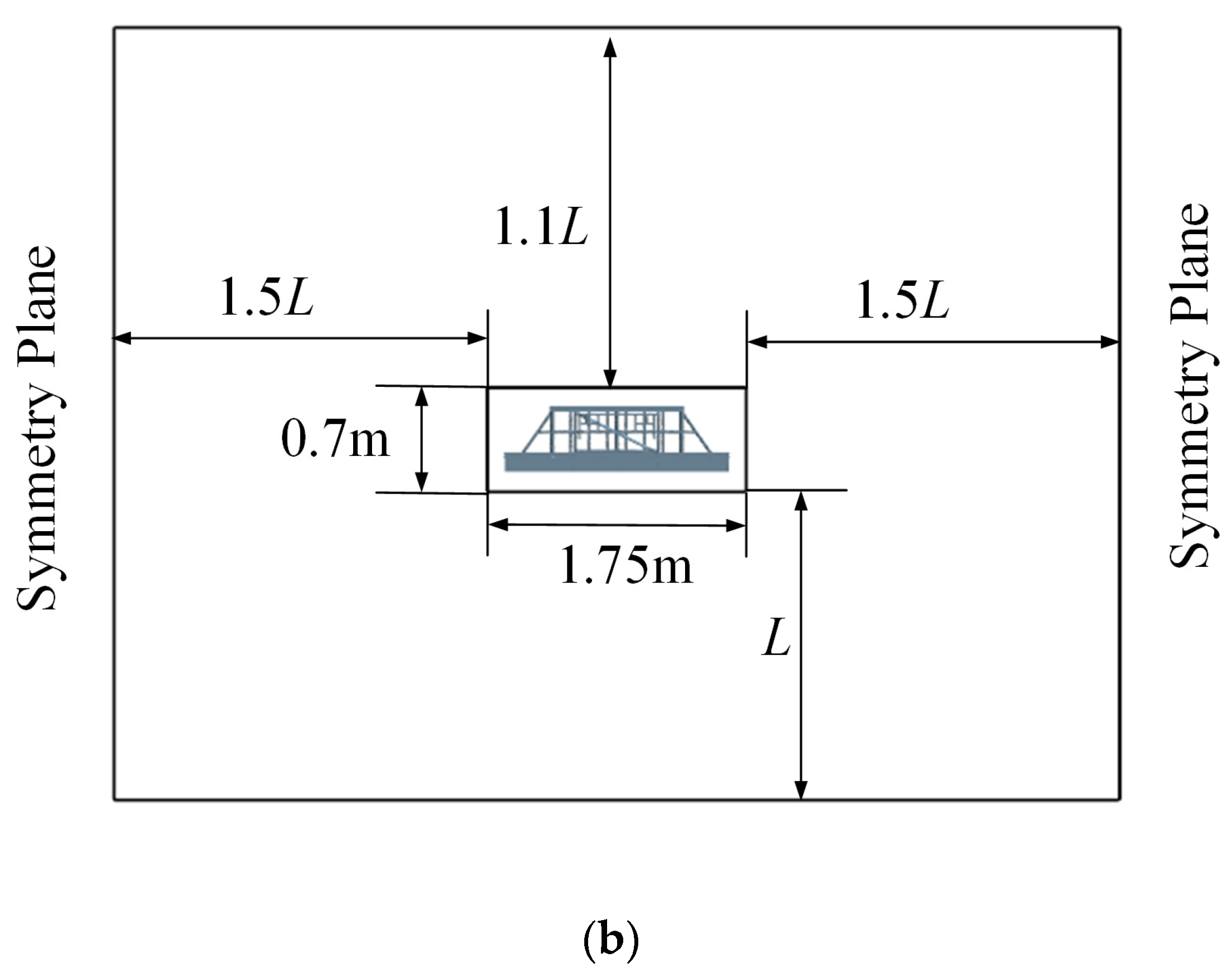
To simulate the vorticity field around the model, a calculation domain was first established for the whole body. In this study, the domain size shown in Figure 8 was adopted. It can be seen that the domain extends for 2 L in front of the overset, 4 L behind the overset, 1.5 L to the side, 1 L below the overset, and 1.1 L above the overset. The distance between the boundaries of the calculation domain and module is more than 2 L in the longitudinal direction and more than L in the lateral and vertical direction when the module has its maximum moving range [22]. The flow is stable between the module and the inlet surface and does not cause backflow within 2 L [23].
The boundary conditions are specified as follows: the model is considered as a moving boundary, and a no-slip condition is imposed on the model surface, symmetry conditions are used for the top, bottom, and side boundaries, at the velocity inlet, the flow velocity is defined as the tested velocity in each case, and at the pressure outlet, the initial hydrostatic pressure is defined as constant.
In this study, we used a spherical joint coupling to replace towropes. The spherical joint restricts the relative motion of the two bodies to a pure rotation about the joint position. A relative translation of the two rigid bodies is not allowed. The spherical joint coupling is often called a ball-and-socket joint. The motion of the spherical joint is the same as for towropes.

3.3. Mesh Generation

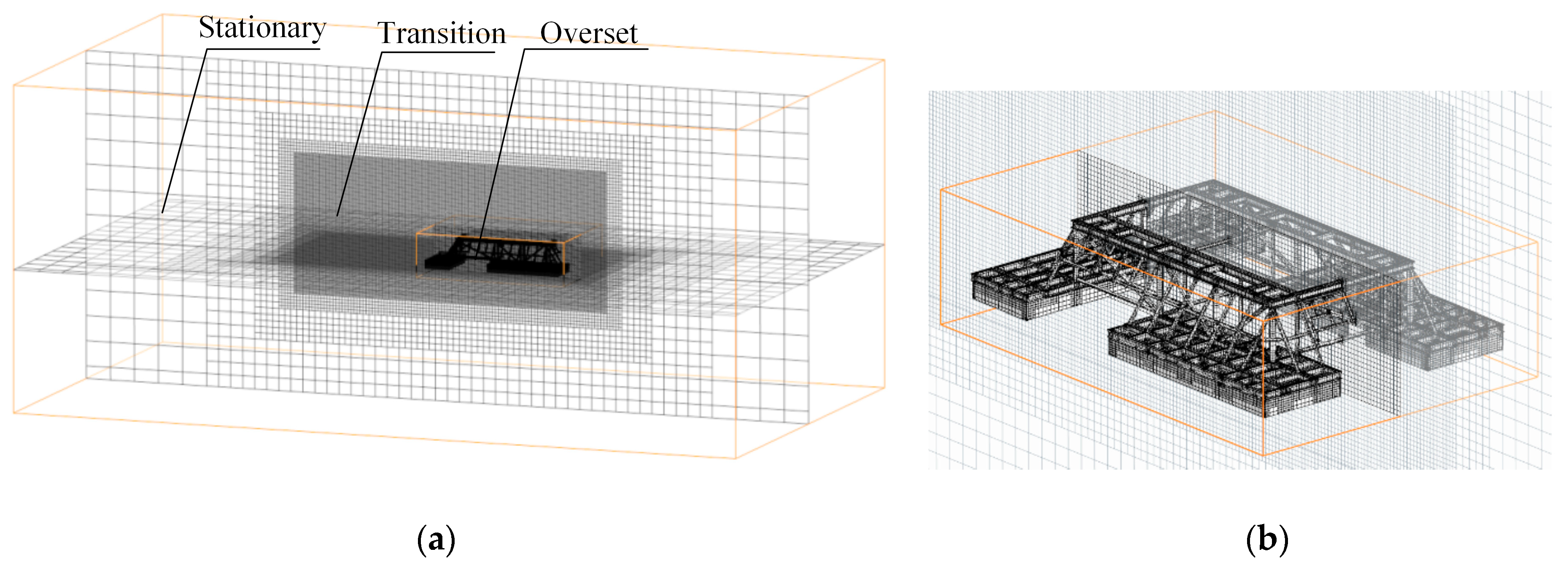
Because the model has a large movement, a dynamic mesh was adopted. As shown in Figure 9, a trimmed cell mesh was used for the discretization of the whole domain. The mesh generation was conducted carefully to ensure computational accuracy. The computational domain was separated into three regions: stationary, transition, and overset [24]. The target size of the mesh was 0.025 m in the overset and transition region to avoid half grids and equates to B/60 and nearly 0.01 L. The minimum size was 2 mm, which can precisely describe the structure of the module. To stabilize the calculation on the interfaces, the boundaries of the overset region were set above four layers from the module. The area of the transition mesh was large enough to include the range of motion, and the boundaries were more than 10 layers from the boundaries of the overset region, even when the offset angle approached the maximum. The model moves with the overset region in the transition region using the overset mesh and Dynamic Fluid Body Interaction (DFBI) solver. The stationary and transition regions did not change during the dynamic mesh process [25]. The total number of cells in the grid was 3,200,593. This fine mesh size provides a good distribution of most of the variables around the model.

4. Result and Discussion

4.1. Validation of Numerical Prediction

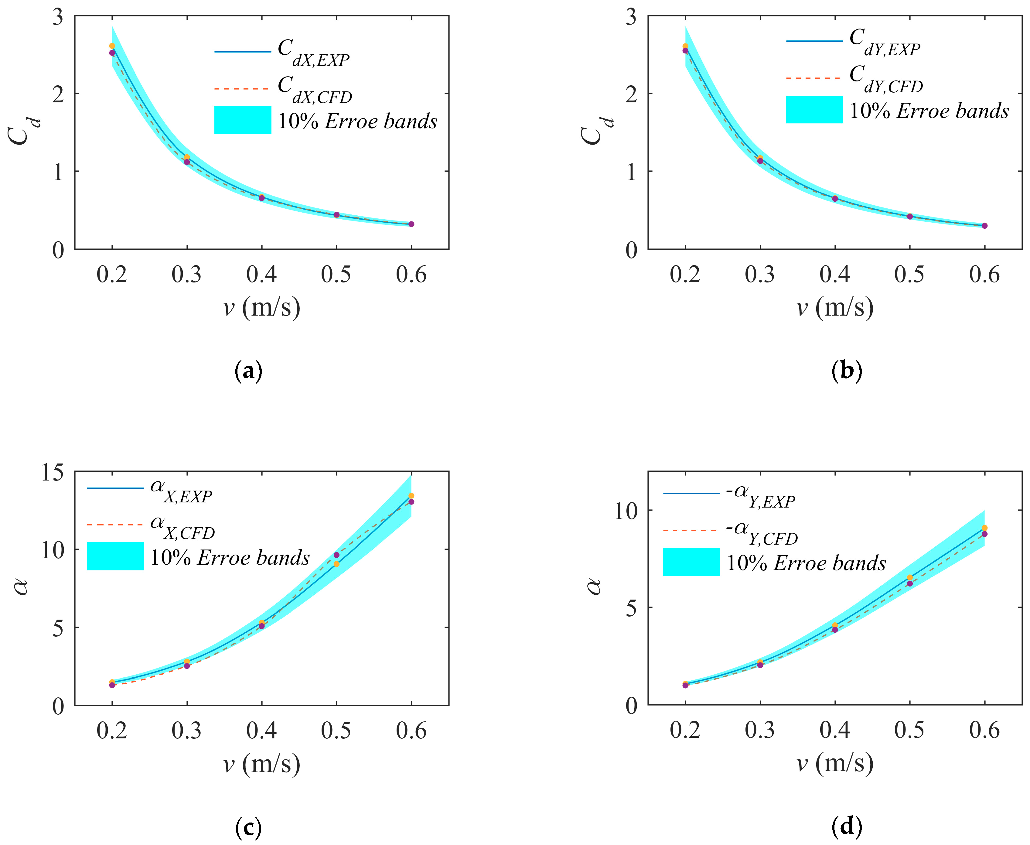
Figure 10 shows the calculated drag force coefficient and the vertical offset angle in comparison with experimental measurements for each case. The drag coefficients decreased non-linearly with velocity. The agreement was reasonable overall for all cases, and the relative error was usually less than 10%. For X-direction towing, the discrepancy between the drag force coefficient from the experimental data ( C d X , E X P ) and numerical data ( C d X , C F D ) was moderately high, especially for Case 2, where the relative difference was 5.4% (the absolute error was only 0.064). In other cases, the relative errors are less than 5%. The vertical offset angle in the X-direction tests ( α X , E X P ) and in simulations ( α X , C F D ) showed good agreement at the highest speeds: their relative difference was lower than 6.4%. The maximum error was 13.1%. However, the maximum absolute error in Cases 1 and 2 was just 0.284°. For Y-direction towing, the relative errors between C d Y , E X P and C d Y , C F D in the numerical simulations and the experiments all varied between 1.0% and 3.2%, which meets the needs of engineering applications. The maximum discrepancy of 0.056 occurred in Case 6. The maximum deviation between the offset angle in experiments ( α X , C F D ) and simulations ( α Y , C F D ) was 8.4% and the average was 5.8%. Although the average error of the offset angle in Y-direction towing appears large, the numerical difference was only about 0.218°, on average.
The comparison of the attitude of the numerical and physical model in a stable towing state is shown in Figure 11. The towing direction is along the X axial of the coordinate system in the Figure. The longitudinal of the model is almost perpendicular to the towing direction and shows the same phenomenon as in Figure 11b. Therefore, the validity of the numerical method is proven.

4.2. Detailed Vorticity Field Analysis

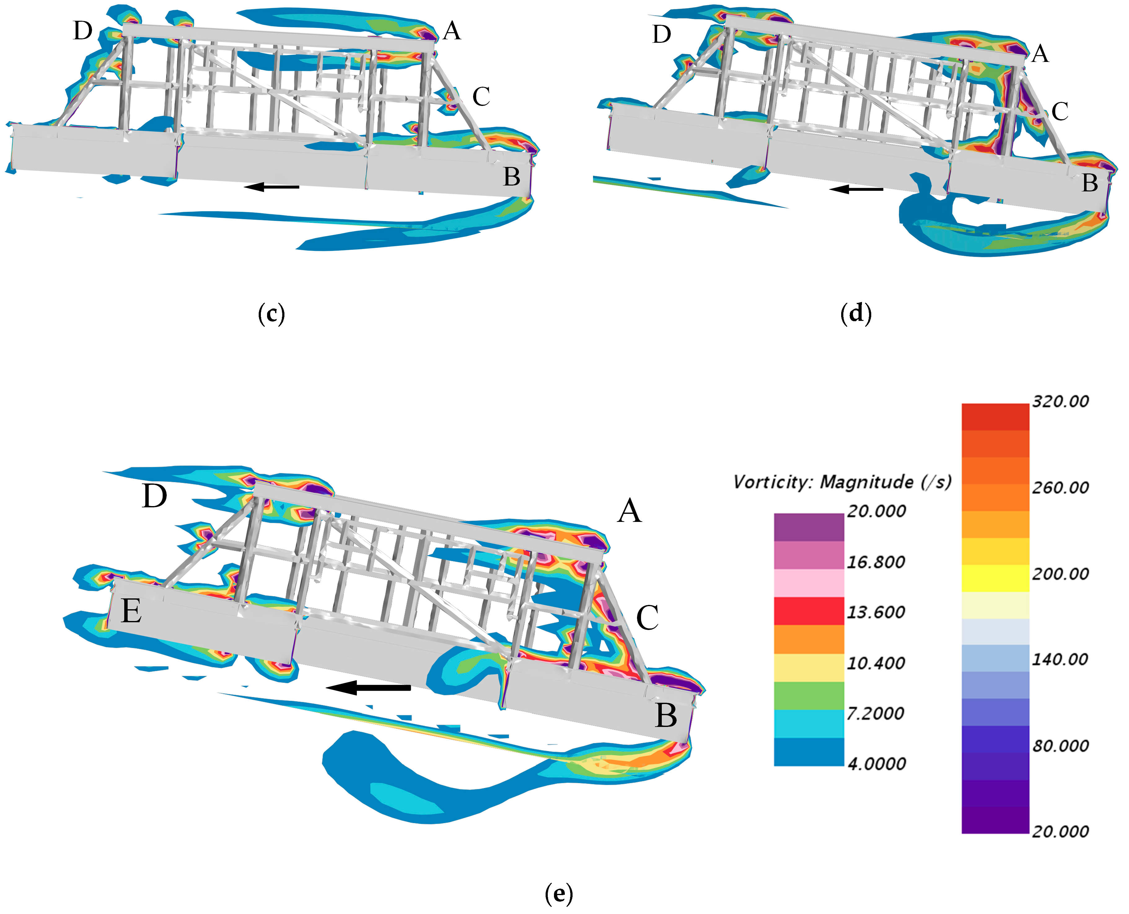
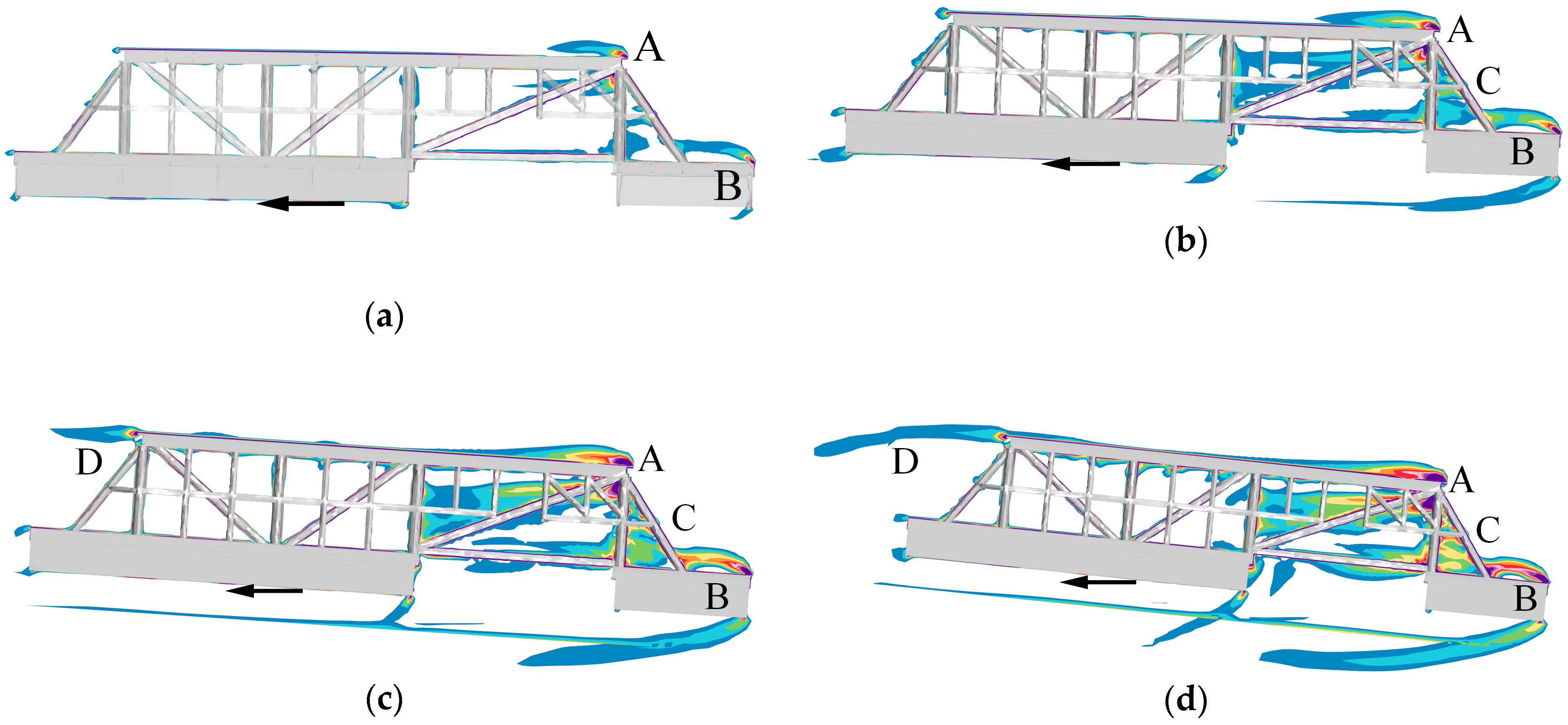
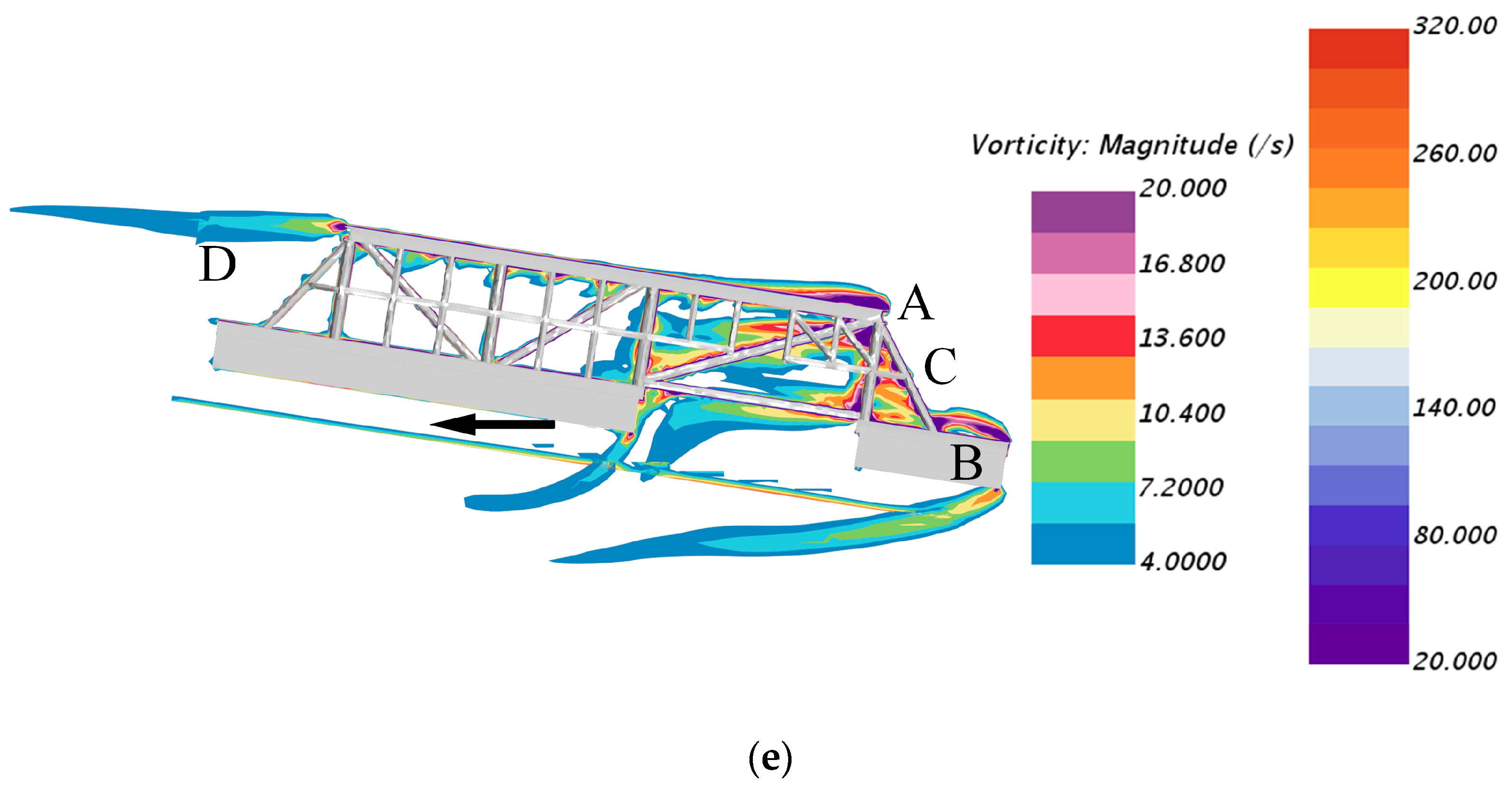
Figure 12 illustrates cross-sections of the flow field where the local velocity component along the negative of the X axial is equal to the speed of Cases 1–5. The cross-sections are colored according to vorticity magnitude. To clearly and carefully describe the flow, two-color bars were adopted. As is shown in Figure 12, there were two main vortexes that appeared in Case 1: one series of the vortex was generated at the top corner in the inlet section of the model (hereafter called vortex A), and another arose at the lower end (hereafter called vortex B). Both vortex A and B occurred mainly along the upper edge of the steel structure, while there was a little vortex at the end of the model in the outlet section. In Case 2, the main vortexes are still vortex A and B, but the distribution is larger than in Case 1. In addition, there were some vortexes being created in the middle of the model behind the steel pipe in the inlet section (hereafter called vortex C). For the intermediate towing velocities (Cases 3 and 4), in addition to vortex A and B, another series of vortexes was generated at the top corner in the outlet section (hereafter called vortex D). For the high towing velocity (Case 6), the distribution of vortex A, B, and C was larger than in the other cases, and another series of vortexes was generated at the lower end of the model in the outlet section (hereafter called vortex E). The reason for the occurrence of vortexes D and E is that the increasing trim angle caused an increase in the area of the incident flow surface in the outlet section. The arrows indicate the direction of the flow.
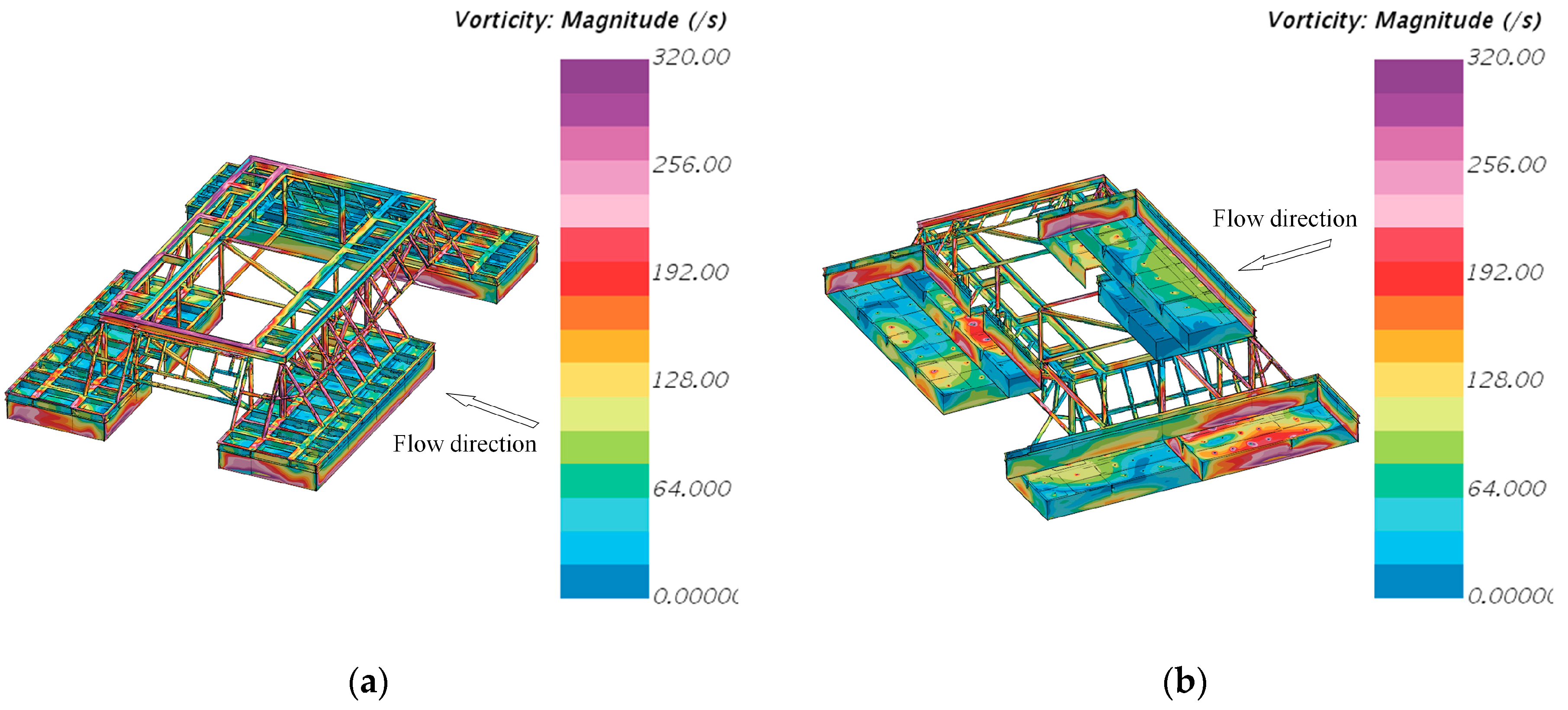
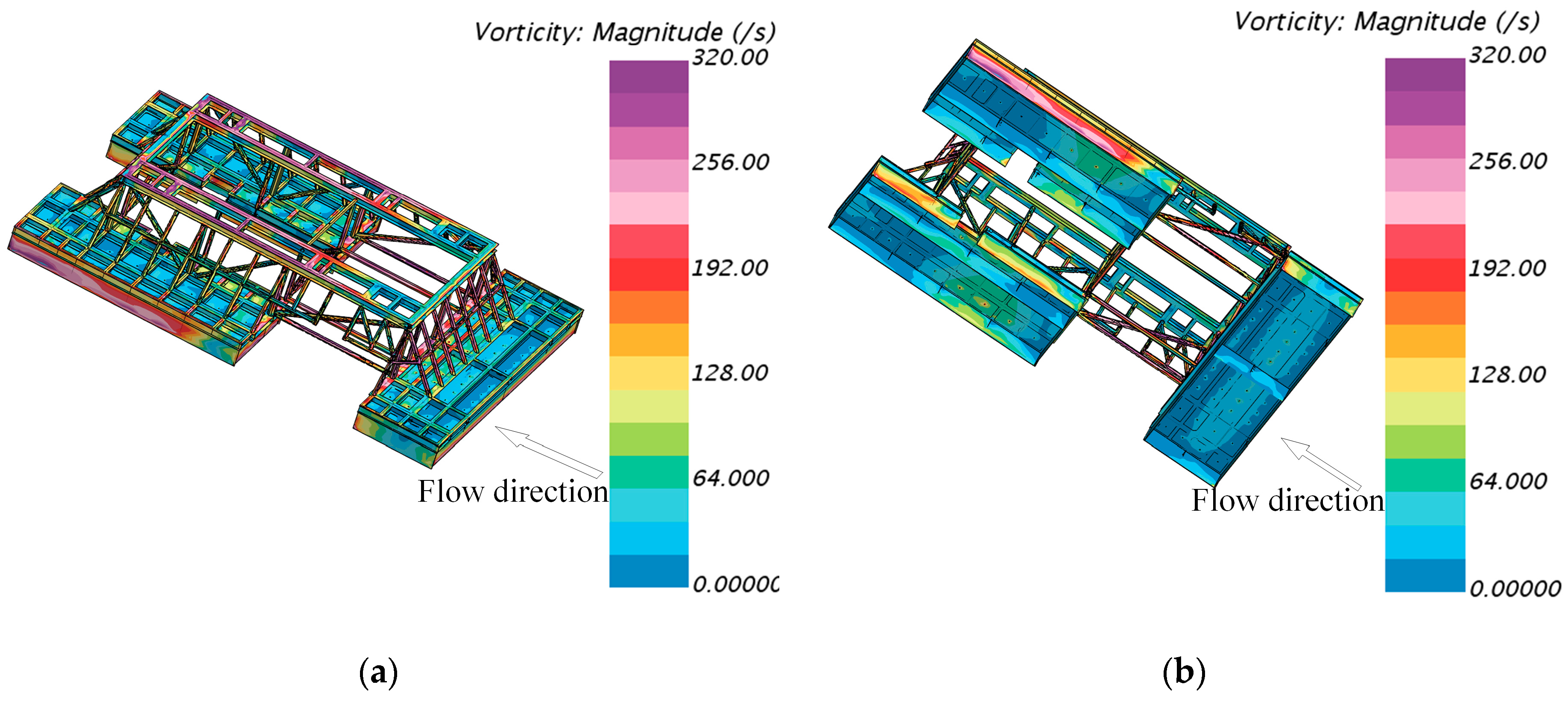
According to the discussion above, the highest number of vortices and the largest distribution of the vortex field occur at high velocities. Therefore, top and bottom views of the vorticity visualization on the surface of the model in Case 5 are shown in Figure 13. The arrow indicates the direction of flow. As illustrated in Figure 13a, some of the high vorticity areas (over 214 Hz) arise at the upper surface on the truss in the outlet section, while others appear in the inlet section of the skirt plates, steel pipes, and at the front of the model. As shown in Figure 13b, there are three main areas with vorticity above 128 Hz under the perforated plates, and they all occur around the holes in the inlet section in rectangular spaces. Even though there are no large areas with high vorticity, the vorticity around the holes was over 192 Hz.
For the Y-direction towing simulations, as shown in Figure 14, vortex A and B appeared in Case 6 to Case 10, and their distribution became wider and larger with the increase in velocity. Vortex C appeared mostly in Cases 7 to 10 and extended from the inlet section to the middle of the model. What is different from Case 1 is that vortex C was found in Case 6 and had a larger extent because there were more complex structures than for the X-direction towing at the inlet section. Vortex D occurred in Cases 8, 9, and 10. What is different from the X-direction towing cases is that the distribution of the vortex was narrower but longer for the same towing speed. Vortex E was not obvious in Y-direction towing cases because the longer perforated plate induced lower vorticity. The existence of the vortexes is the reason for the oscillation in the experimental data. The arrows indicate the direction of the flow.
The vorticity visualization on the surface of the model in Case 10 for top and bottom views is shown in Figure 15. In terms of the direction of flow, the vortex distribution in Y-direction towing is similar to that in Case 6. The difference is that the vortex distribution in Case 10 is nearly symmetrical because of an almost symmetrical model. It is interesting that there are no large areas with a vorticity above 106 Hz, and that there are only two large areas with a vorticity of over 64 Hz. The areas with a vorticity of over 64 Hz are in the outlet section under the perforated plates.

4.3. Detailed Flow Patterns Analysis

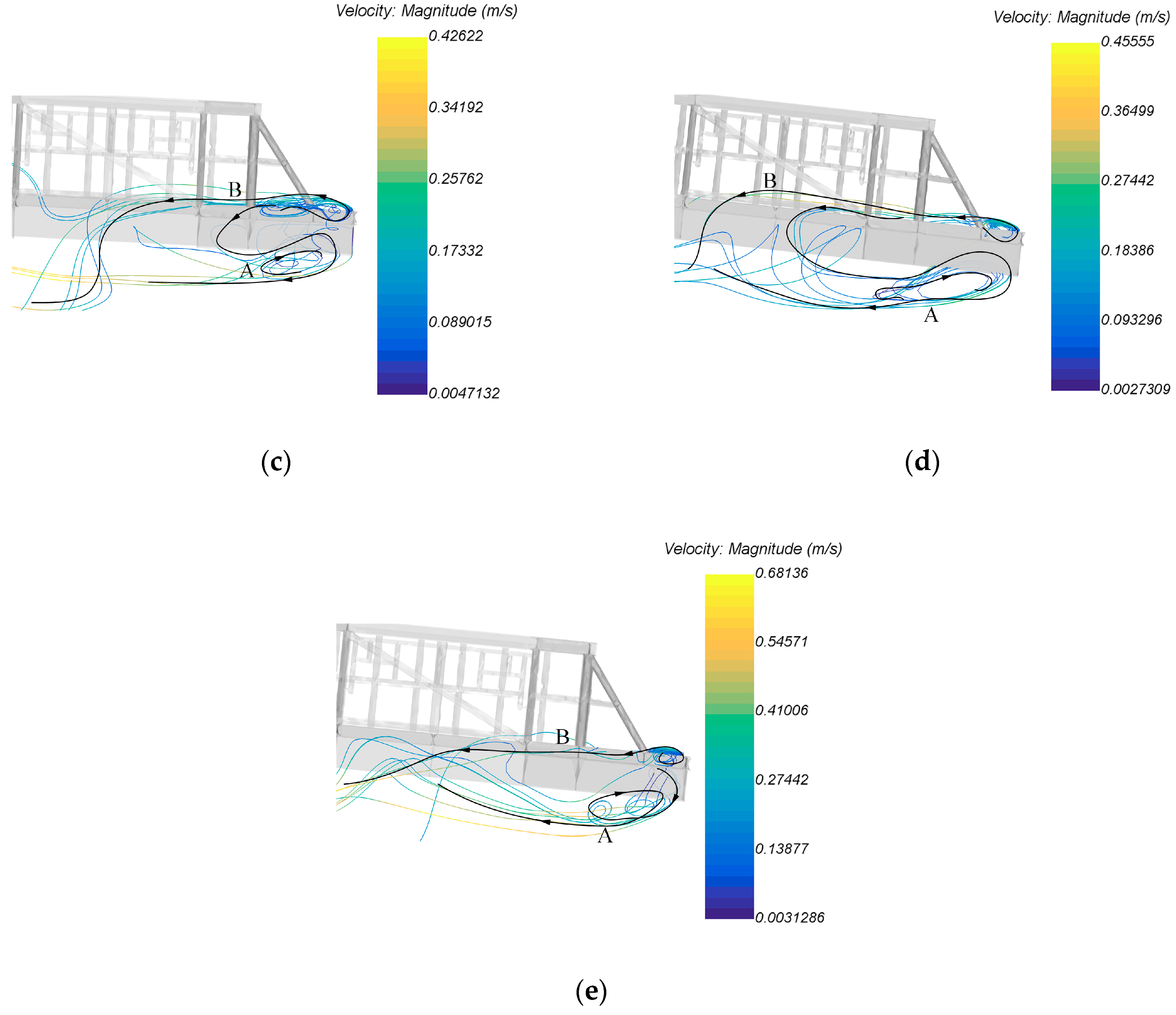
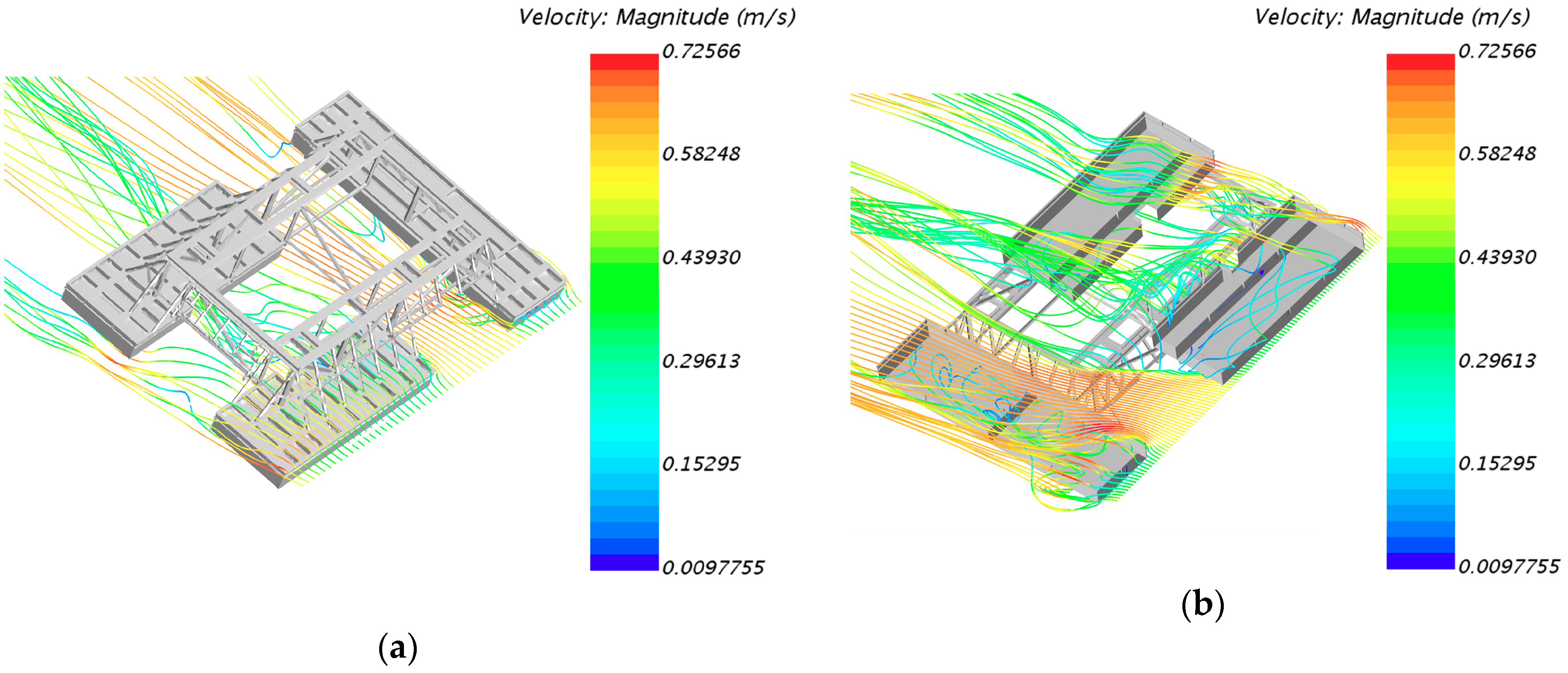
According to the analysis in the previous section, the flow field in the inlet section is more complex than that in the outlet section. Therefore, the detail of the flow pattern for the inlet section is needed. A more detailed set of visualizations is provided in Figure 16, Figure 17, Figure 18 and Figure 19. The streamline inlet line is located near the holes above the perforated plate in the inlet section and is perpendicular to the direction of velocity. In Figure 16, there are two main observed flow patterns: pattern A and pattern B. The streamlines of pattern A, originating from the inlet, propagate according to a recirculating path below the perforated plate induced by external water flow from the velocity inlet surface. The recirculating path is mainly formed by the reflection of the skirt panel in pattern A. The streamlines of pattern B propagate from the inlet line to the middle of the model and then flow below the perforated plate because of the effect of the perforated plate, and finally converge on the streamlines of pattern A. The proportion of pattern A streamlines increased with velocity, and the recirculating path appeared in almost the same place. The recirculating path was not obvious in Case 1 because it was mainly caused by the flow through the holes on the perforated plate at a low velocity. As the towing velocity increased, more streamlines flowed over the perforated plate and were reflected by the skirt panel in the outlet section. The streamlines of pattern B become denser in low-velocity cases, and the streamlines flowed through the top of the perforated plate in Cases 1 and 2 because the trim angle was small and the streamlines were not significantly hindered by the perforated plate, especially in Case 1.
Figure 17 shows plan views of streamlines from the inlet section in Case 6. The streamlines in front of the model flow through the perforated plate and speed up, and are then separated by the steel pipes and flow below the perforated plate in the outlet section, and finally divide into two parts to converge with streamlines from far-field. Some of the front streamlines form large recirculating paths under the perforated plate and are forced to the back of the model. The streamlines at the back of the model flow through the side of the skirt plate to the bottom and form another recirculating path. Some of the streamlines flow down the perforated plate and speed up to converge with streamlines from far-field.
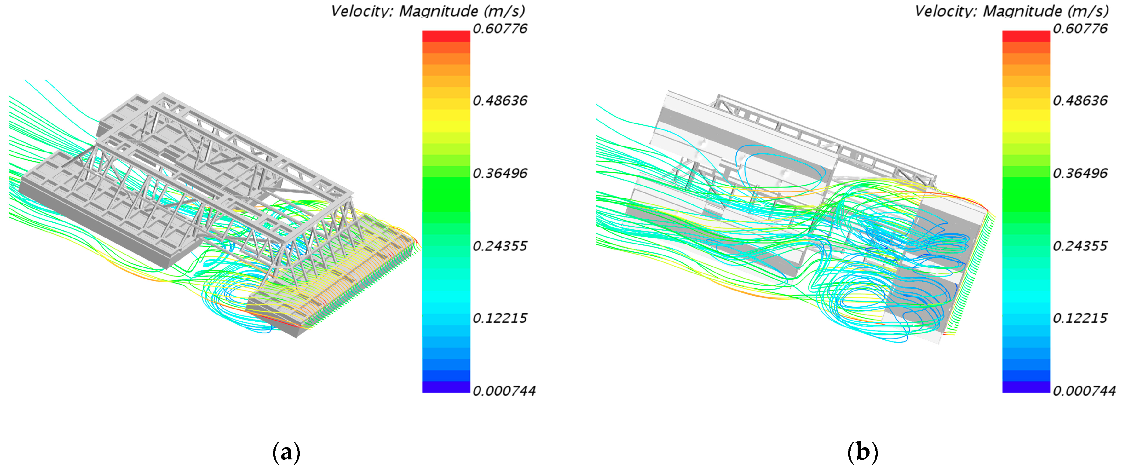
Figure 18 shows inlet flow patterns for Y-direction towing cases. The propagation of streamlines in patterns A and B was similar to that in X-direction cases. The difference is that the recirculating path clearly appears either in low-speed or high-speed cases. This occurs because the length between skirt panels in the Y-direction is larger than in the X-direction, and because there are more holes in the inlet section in the Y-direction. The reason why another distinct recirculating path arises at the middle of the model in Cases 7 and 8 is that the streamlines reflected by the skirt panel can only form an obvious recirculating path in the outlet section at the highest speeds, but the first recirculating path moves back when the speed is too high. Hence, two parts of the recirculating path combine together and are continuously distributed from the inlet section to the middle of the model in Case 10.
Figure 19 shows the perspective view of streamlines from the inlet section in Case 10. As with X-direction towing, the streamlines in front of the model flow through the perforated plate and speed up, are separated by the steel pipes, and then flow below the perforated plate in the outlet section. What is different in the Y-direction towing cases is that the streamlines were divided into three parts, which converge with streamlines from the far-field. The streamlines on the side flow down to the perforated plate to form a recirculating path and flow to the middle of the model. The streamlines in the middle of the model flow to the side because of the flow induction on the side of the model after acceleration, which causes little direct streamline flow through the middle of the model.

4.4. Resistance Component Analysis

Once the total drag force has been obtained, the frictional and pressure resistance components can be calculated. The RANS method calculates the hydrodynamic drag using an integral over the wetted surface [26]. The frictional, pressure and total resistance coefficients are calculated as follows [19]:
C f = F f / 1 2 ρ A U 2
C p v = F p v / 1 2 ρ A U 2
C t = F t / 1 2 ρ A U 2
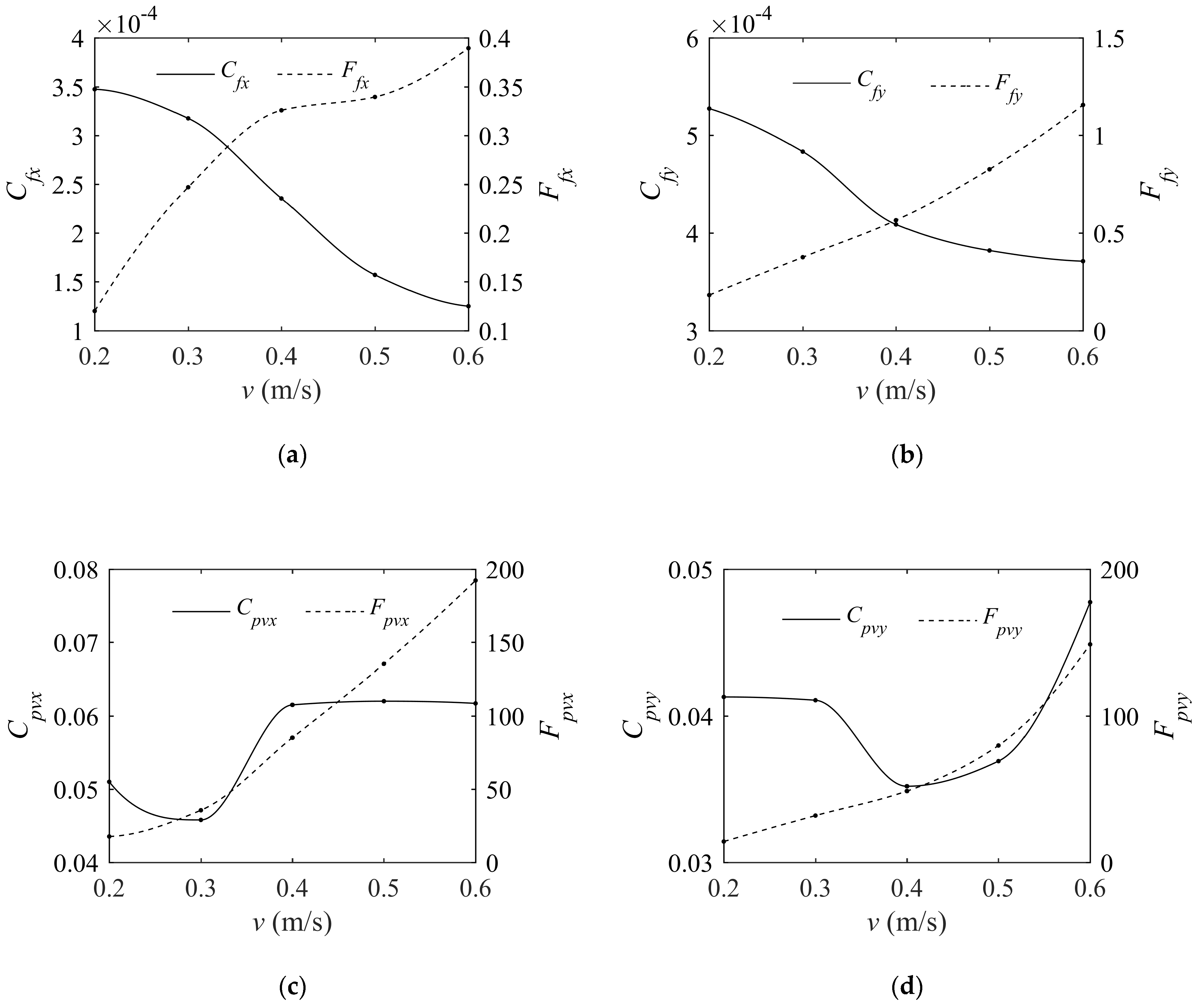
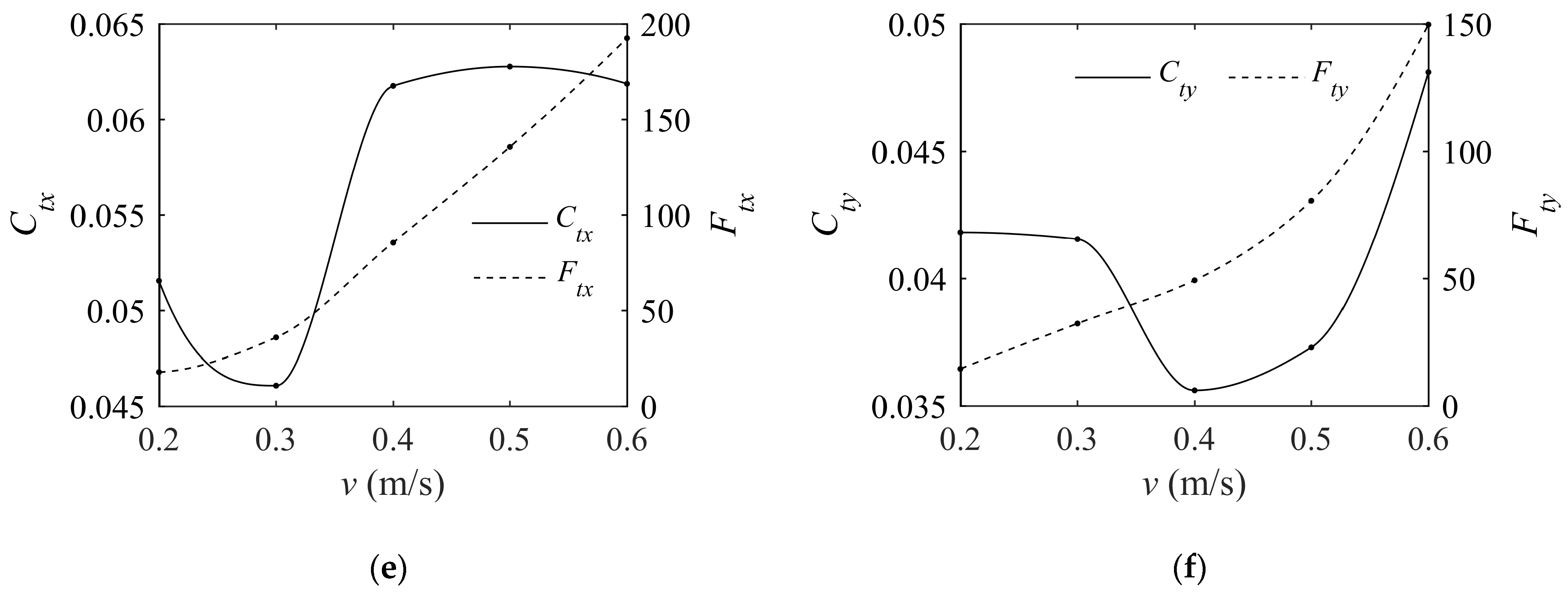
As shown in Figure 20 by the dotted line, the frictional, pressure, and total resistance all increase nonlinearly with velocity. In the X-direction, the frictional resistance F f x increases slowly at high speeds and is very small compared with pressure resistance F p v x . The proportion of F f x to F p v x is 0.69% in the case of 0.3 m/s. The reason for the small ratio of frictional resistance to pressure resistance is that a lot of vortexes appear behind the module, as shown in Figure 12. These vortexes are created by the separation of the boundary layer and the increase in the net pressure difference, and hence the increase in F p v x . The distribution of vortexes increases in the high-speed towing cases and reduces the increase in F f x induced by velocity. In the Y-direction, the frictional resistance F f y is greater than that in the X-direction at the same towing speed because the vortexes are thinner. This is caused by the lag of the separation of the boundary layer. Furthermore, the pressure resistance is less than in the X-direction because of the decrease in the net pressure difference. Since the pressure resistance is the main component of total resistance, the total resistance in the X-direction is greater than in the Y-direction [27].
As shown in Figure 20a,b in solid lines, the frictional drag coefficients in the X-direction ( C f x ) and the Y-direction ( C f y ) decreased as the velocity increased. C f y was larger than C f x for the same towing velocity, and the maximum relative difference (66.3%) was evident at a towing velocity of 0.6 m/s. In contrast, the pressure drag coefficient in the X-direction ( C p v x ) was larger than in the Y-direction ( C p v y ). The maximum relative difference (74.8%) appeared at a towing velocity of 0.4 m/s. Initially, C p v x reached its minimum at 0.3 m/s. The reason for this is that the Re number is greater than 3 × 10 5 and laminar flow becomes turbulent before the separation of the laminar boundary layer. The pressure resistance induced by the net pressure difference increased slightly when the turbulent boundary layer separated. Therefore, C p v x clearly decreased, indicating the same phenomenon but with a different threshold for the Re number as a cylinder [28]. With increased towing speed, C p v x increased to around 0.062 when the Re number was greater than 9.6 × 10 5 because the location of the boundary layer separation stops moving forward. In the Y-direction, the turbulent boundary layer separated after 0.3 m/s, and the C p v y reached its minimum at the speed of 0.4 m/s. However, C p v y still increased because the location of the boundary separation was still moving forward. Finally, C p v y reaches its maximum (0.0477) at 0.6 m/s. The variation in the total drag coefficient ( C t ) was similar to that of C p v because of the larger pressure drag component.

5. Conclusions

The present study initially used a physical model to investigate the drag force and vertical offset angle of the towrope of a subsea module, and to analyze the underwater attitude and flow field characteristics. It is interesting to note that the drag force and offset angle are smaller in lateral direction towing cases. The difference between the offset angles of longitudinal and lateral direction cases is more obvious than the difference between the drag force coefficients. These characteristics were then reproduced in a numerical simulation.
The numerical simulation results for the drag force coefficient and offsets angle were in agreement with the physical model results. Most of the differences in the drag force coefficients and offset angles were less than 10%. Thus, it was shown that the CFD solver, numerical methods, and computing grids can be applied for the purpose of accurate and efficient drag force and offset angle estimation in relation to underwater towing operations.
By analyzing the detailed vorticity fields around the module, we found that there were three kinds of vortexes in the inlet section that appeared in both the longitudinal and lateral direction towing cases. However, the distribution of vortexes in the lateral direction was narrower than in the longitudinal direction. In addition, the detailed flow field in the inlet section was analyzed: two main flow patterns were found and were broadly similar for longitudinal direction and lateral direction towing. Streamlines flow through holes and form recirculating paths in high-speed cases, and another recirculating path appears in middle-speed cases in lateral-direction towing because of the longer length between the skirt panels. Further analysis was provided of 3D flow in the longitudinal direction and lateral direction towing cases at the highest speed. The phenomena presented by fluid flow is in agreement with the experimental data. Thus, the CFD method used in this paper can reflect the flow detail of the module.
Finally, the frictional, pressure, and resistance coefficients were studied. The distribution of vortexes affects resistance significantly. There were greater frictional resistance and less pressure resistance in the lateral direction, ultimately leading to less total resistance. According to the comparison of the pressure coefficients, the turbulence boundary layer separates at greater Reynolds numbers, and the location of the separation was further forward in the lateral direction than in the longitudinal direction. Thus, it is clear that resistance coefficients need to be assessed when considering different towing directions.
In general, lateral-direction towing is more effective for towing operations of the module than longitudinal-direction towing. In the lateral direction, the offset angle and drag force at low speeds are smaller. The drag force and its oscillation increase slightly with the towing speed. The resistance is smaller, and this reduces potential damage to the structure. Attention should be paid to a sudden increase in drag force and offset angle when increasing the velocity of tugboats, even in low-speed towing operations. Towing operations also place restrictions on the attitude of the module, especially in the starting state, because the heading angle of the module will change from the initial state.

Author Contributions

This paper is the result of collaborative teamwork. R.G. wrote the paper, Y.Z. and L.Y. reviewed and edited the text, Y.Z. analyzed the data, and Z.W. obtained the resource data. All authors approved the manuscript.

Funding

This research was funded by the National Natural Science Foundation of China (Grant No. 51809067), the Fundamental Research Funds for the Central Universities (Grant Nos. 3072019CFM0101 and 3072019CF0102), and the National Science and Technology Major Project of China (Grant No. 2016ZX05057020).

Acknowledgments

The authors thank Chiahsing Liu at SIEMENS for his technical support in the simulation setting.

Conflicts of Interest

The authors declare no conflict of interest.

References

  1. Nam, B.W.; Kim, N.W.; Hong, S.Y. Experimental and numerical study on coupled motion responses of a floating crane vessel and a lifted subsea manifold in deep water. Int. J. Naval Archit. Ocean Eng. 2017, 9, 552–567. [Google Scholar] [CrossRef]
  2. Ramos, R.V.; Camponogara, E.; Martins, F.F.V.J. Design optimization of oilfield subsea infrastructures with manifold placement and pipeline layout. Comput. Chem. Eng. 2018, 108, 163–178. [Google Scholar] [CrossRef]
  3. Neto, E.D.A.; Jacovazzo, B.M.; Correa, F.N.; Jacob, B.P. Numerical evaluation of a subsea equipment installation method designed to avoid resonant responses. Appl. Ocean Res. 2019, 88, 288–305. [Google Scholar] [CrossRef]
  4. Olsen, T.A. Subsurface Towing of Heavy Module. Master’s Thesis, Norwegian University of Science and Technology, Trondheim, Norway, 6 January 2011. [Google Scholar]
  5. Risoey, T.; Mork, H.; Johnsgard, H.; Gramnaes, J. The pencil buoy method—A subsurface transportation and installation method. Offshore Technol. Conf. 2007, 30, 1–7. [Google Scholar] [CrossRef]
  6. Yamazu, T.; Haraguchi, K.; Inoue, T.; Arai, K. Development of a Highly Flexible and High-Resolution Deep-Towed Streamer. J. Mar. Sci. Eng. 2019, 7, 254. [Google Scholar] [CrossRef]
  7. Jacobsen, T. Subsurface Towing of a Subsea Module. Master’s Thesis, Norwegian University of Science and Technology, Trondheim, Norway, 6 June 2010. [Google Scholar]
  8. Kang, W.H.; Zhang, C.; Yu, J. Stochastic extreme motion analysis of jack-up responses during wet towing. Ocean Eng. 2016, 111, 56–66. [Google Scholar] [CrossRef]
  9. Zhang, P.; Peng, Y.; Ding, H.; Hu, R.; Shi, J. Numerical analysis of offshore integrated meteorological mast for wind farms during wet towing transportation. Ocean Eng. 2019, 188, 106271–106283. [Google Scholar] [CrossRef]
  10. Ding, H.; Hu, R.; Le, C. Towing Operation Methods of Offshore Integrated Meteorological Mast for Offshore Wind Farms. J. Mar. Sci. Eng. 2019, 7, 100. [Google Scholar] [CrossRef]
  11. Rattanasiri, P.; Wilson, P.A.; Phillips, A.B. Numerical investigation of a fleet of towed AUVs. Ocean Eng. 2014, 80, 25–35. [Google Scholar] [CrossRef] [Green Version]
  12. Wu, J.; Ye, J.; Yang, C.; Chen, Y.; Tian, H.; Xiong, X. Experimental study on a controllable underwater towed system. Ocean Eng. 2005, 32, 1803–1817. [Google Scholar] [CrossRef]
  13. Go, G.; Ahn, H.T. Hydrodynamic derivative determination based on CFD and motion simulation for a tow-fish. Appl. Ocean Res. 2019, 82, 191–209. [Google Scholar] [CrossRef]
  14. Sun, F.J.; Zhu, Z.H.; LaRosa, M. Dynamic modeling of cable towed body using nodal position finite element method. Ocean Eng. 2011, 38, 529–540. [Google Scholar] [CrossRef]
  15. Wu, J.; Chwang, A.T. Experimental investigation on a two-part underwater towed system. Ocean Eng. 2001, 28, 735–750. [Google Scholar] [CrossRef]
  16. Wu, J.; Chwang, A.T. Investigation on a two-part underwater manoeuvrable towed system. Ocean Eng. 2001, 28, 1079–1096. [Google Scholar] [CrossRef]
  17. Wu, J.; Chwang, A.T. A hydrodynamic model of a two-part underwater towed system. Ocean Eng. 2000, 27, 455–472. [Google Scholar] [CrossRef]
  18. Jacobsen, T.; Leira, B.J. Numerical and experimental studies of submerged towing of a subsea template. Ocean Eng. 2012, 42, 147–154. [Google Scholar] [CrossRef]
  19. Elkafas, A.G.; Elgohary, M.M.; Zeid, A.E. Numerical study on the hydrodynamic drag force of a container ship model. Alex. Eng. J. 2019. [Google Scholar] [CrossRef]
  20. STAR-CCM+ Users’ Guide Version 13.04. In CD-Adapco, Computational Dynamics-Analysis & Design; Application Company Ltd.: Melville, NY, USA, 2018.
  21. Zhang, X.; Lin, Z.; Mancini, S.; Li, P.; Li, Z.; Liu, F. A Numerical Investigation on the Flooding Process of Multiple Compartments Based on the Volume of Fluid Method. J. Mar. Sci. Eng. 2019, 7, 211. [Google Scholar] [CrossRef]
  22. Jiang, Y.; Sun, H.; Zou, J.; Hu, A.; Yang, J. Experimental and numerical investigations on hydrodynamic and aerodynamic characteristics of the tunnel of planing trimaran. Appl. Ocean Res. 2017, 63, 1–10. [Google Scholar] [CrossRef]
  23. Gao, T.; Wang, Y.; Pang, Y.; Chen, Q.; Tang, Y. A time-efficient CFD approach for hydrodynamic coefficient determination and model simplification of submarine. Ocean Eng. 2018, 154, 16–26. [Google Scholar] [CrossRef]
  24. Pan, Y.; Zhang, H.; Zhou, Q. Numerical Prediction of Submarine Hydrodynamic Coefficients using CFD Simulation. J. Hydrodyn. 2012, 24, 840–847. [Google Scholar] [CrossRef]
  25. Saranjam, B. Experimental and numerical investigation of an unsteady supercavitating moving body. Ocean Eng. 2013, 59, 9–14. [Google Scholar] [CrossRef]
  26. Maki, K.J.; Broglia, R.; Doctors, L.J.; Di Mascio, A. Numerical investigation of the components of calm-water resistance of a surface-effect ship. Ocean Eng. 2013, 72, 375–385. [Google Scholar] [CrossRef]
  27. Molin, B. Hydrodynamique Des Structures Offshore, 1st ed.; National Defense Industry Press: Beijing, China, 2012; pp. 100–103. [Google Scholar]
  28. Cantwell, B.; Coles, D. An experimental study of entrainment and transport in the turbulent near wake of a circular cylinder. J. Fluid Mech. 1983, 136, 321–374. [Google Scholar] [CrossRef] [Green Version]
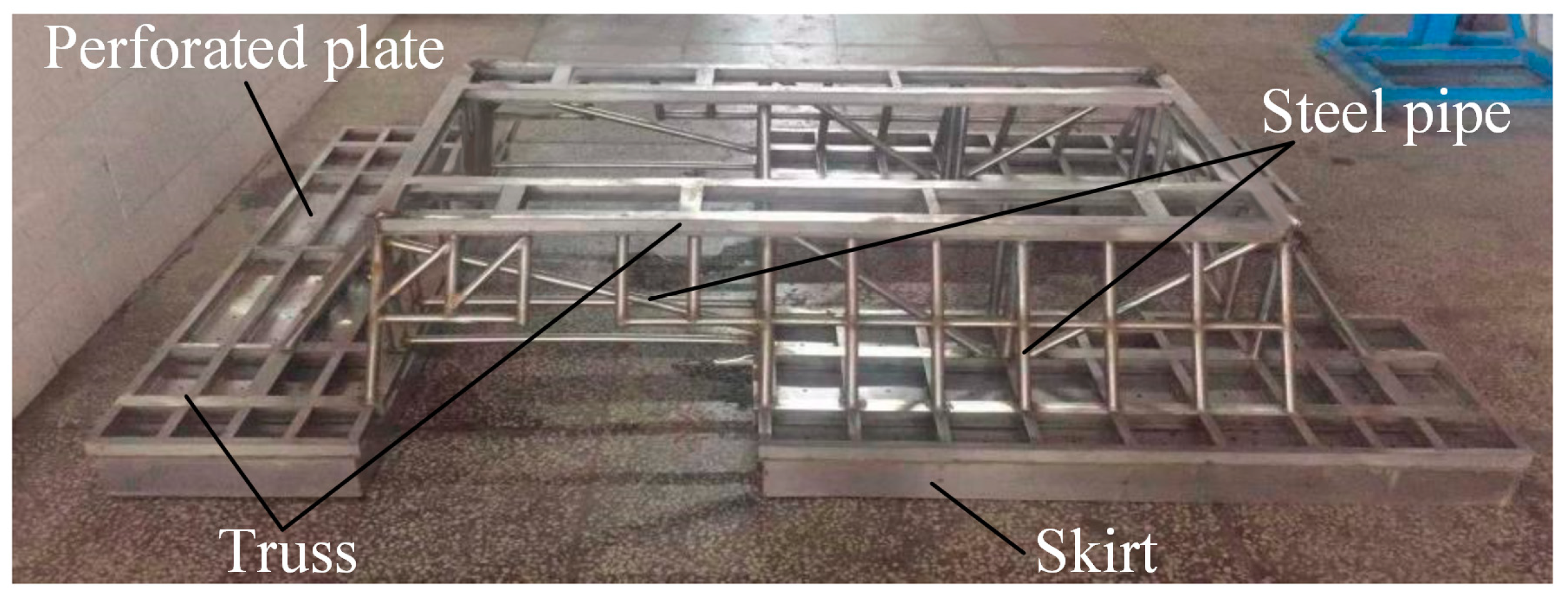
Figure 1. Photograph of the physical model.
Jmse 07 00384 g001
Figure 2. Principal layout of the test module: (a) side view, (b) front view, (c) isometric drawing, (d) top view.
Jmse 07 00384 g002aJmse 07 00384 g002b
Figure 3. Arrangement of experimental equipment.
Jmse 07 00384 g003
Figure 4. The force analysis of an object suspended by a wire.
Jmse 07 00384 g004
Figure 5. Time histories of drag force and vertical offset angle with different speeds: (a) Offset angle variation for X-direction towing, (b) Drag force variation for X-direction towing, (c) Offset angle variation for Y-direction towing, (d) Drag force variation for Y-direction towing.
Jmse 07 00384 g005
Figure 6. Comparison of average drag coefficients and offset angles: (a) Drag force coefficient variation for X and Y-direction towing, (b) Offset angle variation for X and Y-direction towing.
Jmse 07 00384 g006
Figure 7. Change in attitude of the model in the towing experiment: (a) offset angle is at a maximum, (b) offset angle decreasing, (c) transitional phase, (d) transitional phase, and (e) stable.
Jmse 07 00384 g007
Figure 8. Computational domain and boundary conditions: (a) Side view of the computational domain, (b) Front view of the computational domain.
Jmse 07 00384 g008aJmse 07 00384 g008b
Figure 9. Computational mesh: (a) Mesh arrangement in the computational domain, (b) Mesh arrangement on the model.
Jmse 07 00384 g009
Figure 10. Drag coefficient and offset angle variations with velocity in experiments and simulations: (a) The variation of drag coefficient with towing speed in X-direction towing, (b) The variation of drag coefficient with towing speed in Y-direction towing, (c) The variation of offset angle with towing speed in X-direction towing, (d) The variation of offset angle with towing speed in Y-direction towing.
Jmse 07 00384 g010
Figure 11. Stable towing state in Case 4: (a) Attitude of the module in the simulation, (b) Attitude in the experiment.
Jmse 07 00384 g011
Figure 12. Cross-sections of the vortex flow field colored according to vorticity magnitude for X-direction towing: (a) Case 1, α X , C F D = 1.295°, (b) Case 2, α X , C F D = 2.510°, (c) Case 3, α X , C F D = 5.073°, (d) Case 4, α X , C F D = 9.634°, and (e) Case 5, α X , C F D = 13.038°.
Jmse 07 00384 g012aJmse 07 00384 g012b
Figure 13. Vorticity visualization on the surface of the model in Case 5: (a) The top view of the flow field, (b) Lower view of the flow field.
Jmse 07 00384 g013
Figure 14. Cross-sections of flow field colored according to vorticity magnitude for Y-direction towing: (a) Vortex field in Case 6, α Y , C F D = 0.974°, (b) Vortex field in Case 7, α Y , C F D = 2.018°, (c) Vortex field in Case 8, α Y , C F D = 3.838°, (d) Vortex field in Case 9, α Y , C F D = 6.218°, (e) Vortex field in Case 10, α Y , C F D = 8.770°.
Jmse 07 00384 g014aJmse 07 00384 g014b
Figure 15. Vorticity visualization on the surface of the model in Case 10: (a) Top view of the flow field, (b) Bottom view of the flow field.
Jmse 07 00384 g015
Figure 16. Flow patterns in the inlet section for X-direction towing cases: (a) Flow patterns in Case 1, (b) Flow patterns in Case 2, (c) Flow patterns in Case 3, (d) Flow patterns in Case 4, (e) Flow patterns in Case 5.
Jmse 07 00384 g016aJmse 07 00384 g016b
Figure 17. Plan view of streamlines from the inlet section in Case 6: (a) top of the flow field, (b) bottom of the flow field.
Jmse 07 00384 g017
Figure 18. Flow patterns in the inlet section for the Y-direction towing cases: (a) Case 6, (b) Case 7, (c) Case 8, (d) Case 9, and (e) Case 10.
Jmse 07 00384 g018
Figure 19. Perspective view of streamlines from the inlet section in Case 10: (a) top view of the flow field, (b) bottom view of the flow field.
Jmse 07 00384 g019
Figure 20. The variation of the resistance coefficients: (a) frictional resistance coefficient in the X-direction, (b) frictional resistance coefficient in the Y-direction, (c) pressure resistance coefficient in the X-direction, (d) pressure resistance coefficient in the Y-direction, (e) total resistance coefficient in the X-direction, (f) total resistance coefficient in the Y-direction.
Jmse 07 00384 g020aJmse 07 00384 g020b
Table 1. Towed test cases.
Towing Direction: XVelocity/m·s−1Towing Direction: YVelocity/m·s−1
Case 10.2Case 6−0.2
Case 20.3Case 7−0.3
Case 30.4Case 8−0.4
Case 40.5Case 9−0.5
Case 50.6Case 10−0.6
Table 2. Variation in drag coefficient and offset angle with velocity.
Velocity/m·s−1 C d X , E X P C d Y , E X P Δ C d % α X ,   E X P / ° α Y , E X P / ° Δ α %
0.22.6072.6030.151.4901.06328.7
0.31.1801.1671.12.7942.16822.4
0.40.6670.6522.25.3014.07223.2
0.50.4310.4192.89.0536.53527.8
0.60.3160.2995.413.4309.07332.4