A New Solution for Sea Wave Energy Harvesting, the Proposal of an Ironless Linear Generator


Abstract
:1. Introduction
- The power density is higher in comparison with other RES, therefore these power plants require a lower extension;
- Sea wave is more regular than wind, increasing the annual operative hours of these systems;
- The visual impact is lower than other RES technologies, since most devices for sea wave exploitation are located close to sea level;
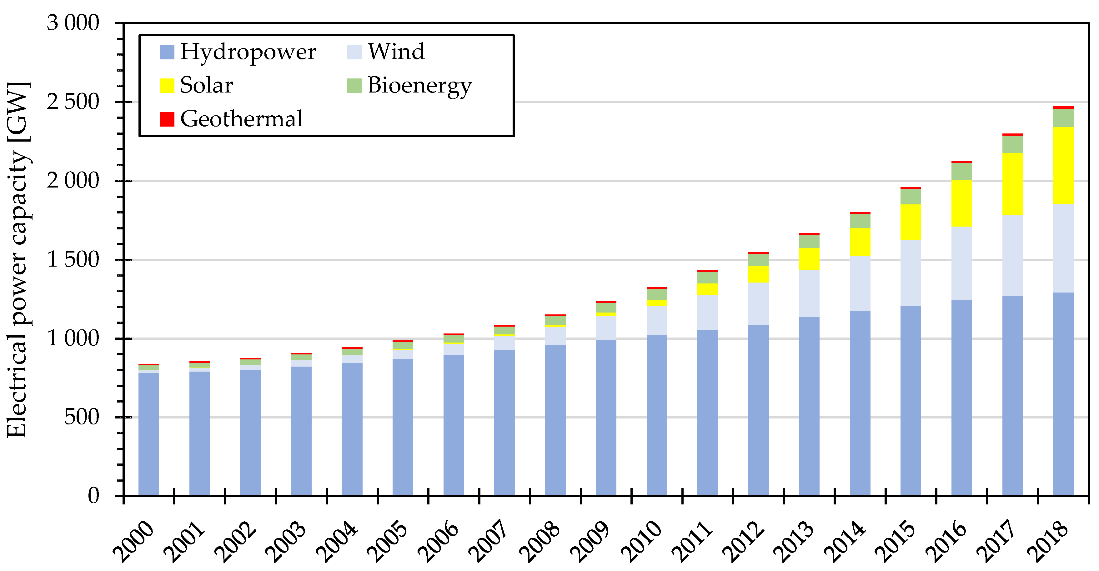
- The energy potential is still enough to meet a significant portion of the world’s energy demand (26.59 PWh/y in 2018) [4].
- Attenuator is generally composed by a floating device oriented along the wave direction. This kind of system rides the crest of waves in order to produce a relative motion between the sections of which it is composed, running the internal energy converters [17].
- Point absorber is a system characterized by axial symmetry, in order to work independently of wave direction [18].
- Oscillating wave surge converters are designed for a nearshore application. Indeed, the system is composed by a barrier, fixed on a seabed by a hinge, in order to oscillate as a pendulum, according to the wave motion in shallow water [19].
- Submerged pressure differential devices are installed on a seabed. They are composed by a fixed part and a movable one. The variation of the hydrostatic pressure on the device generates a vertical motion, usable to activate linear generators or hydraulic pumps [20].
- Overtopping systems are composed of a water reservoir above sea level. By using a ramp, the kinetic energy of waves is converted into potential, refilling the reservoir. The accumulated water is used to run a low-head water turbine [21].
- Rotating mass systems are equipped with big masses installed inside with an eccentric. The oscillation produced by waves (mainly pitch and roll) induces the rotation of the masses, accumulating kinetic energy usable by rotary generator to produce electrical energy [22].
1.1. Background on Linear Generator Topology
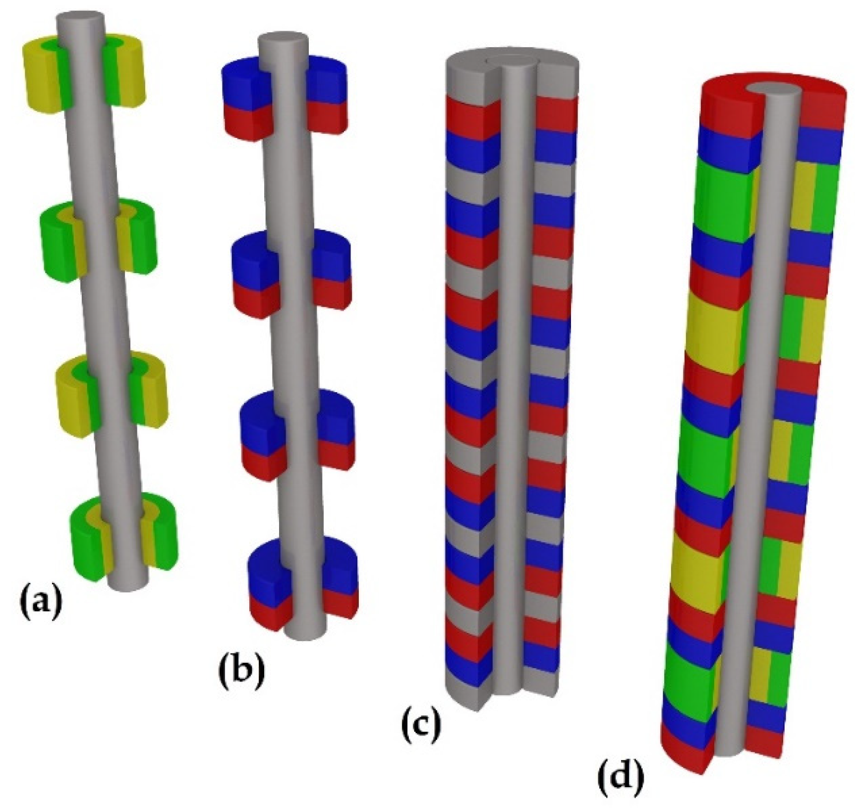
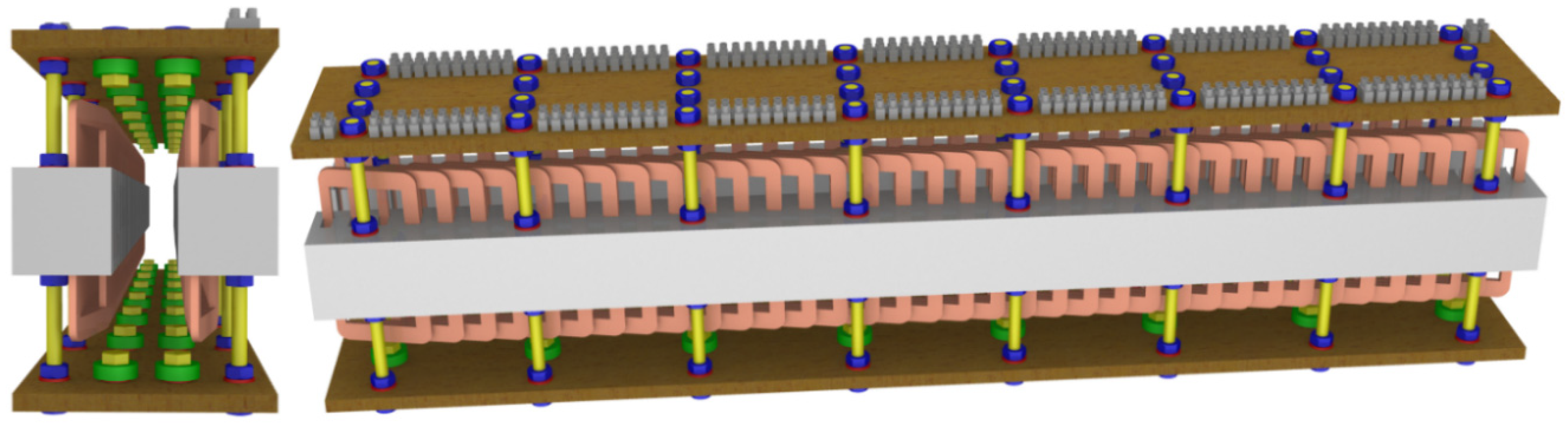
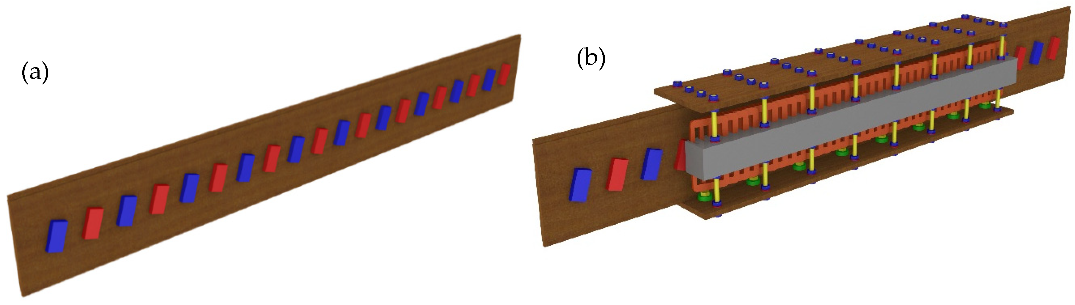
- Structure of generator: flat structure—a generator having a planar symmetry, such as the system proposed in the paper (see the following section); or tubular structure—if stator and translator have an axial symmetry, such as two coaxial cylinders (see Figure 2).
- Length of translator in comparison with the stator: long translator—if the translator is longer than the stator; or a short translator, in the other case.
- Position of translator in comparison with the stator: external translator—if the translator moves in a region outside the stator; or internal translator—if the translator is installed inside the stator region.
- Place where the permanent magnets are installed: stator PM—if magnets are installed on the stator; or translator PM—if magnets are located on the translator.
2. Materials and Methods
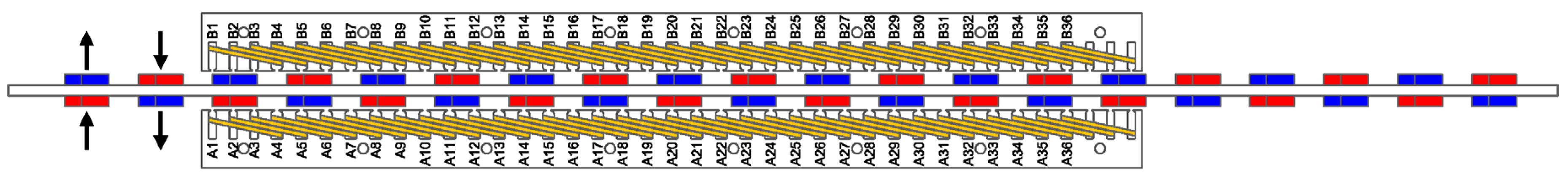
2.1. The Prototype
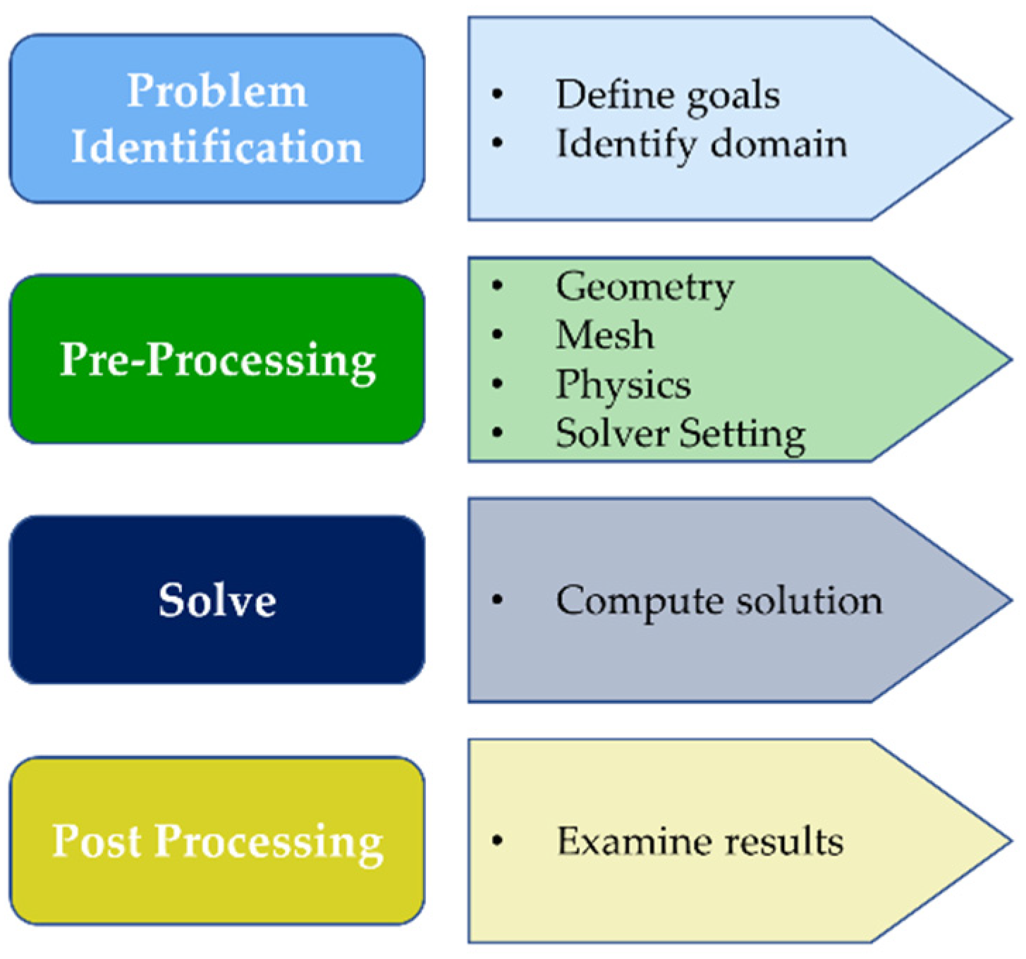
2.2. Numerical Approach
- Magneto-static solution type: a static magnetic field is solved resulting from permanent magnets and it represents a no time variable study. The definition of magnetic properties of materials is essential. This environment is useful to analyse the cogging force.
- Transient solution type: a simulation that computes the time varying magnetic and electric fields. This is a time domain solver, necessary to analyse the induced voltage in the output coils, because of the time variation of the magnetic field, produced by the translation of permanent magnets through the stator.
3. Results
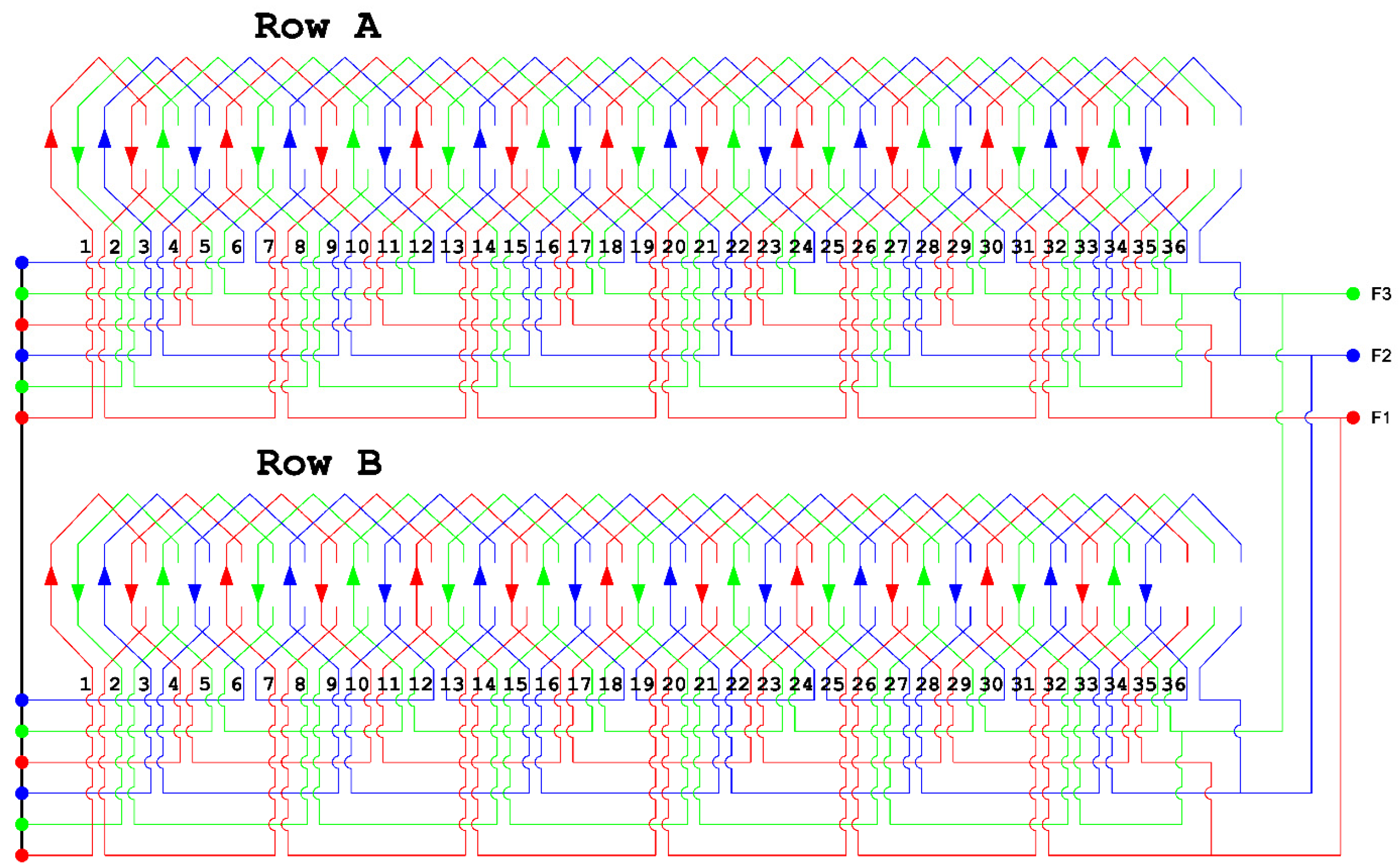
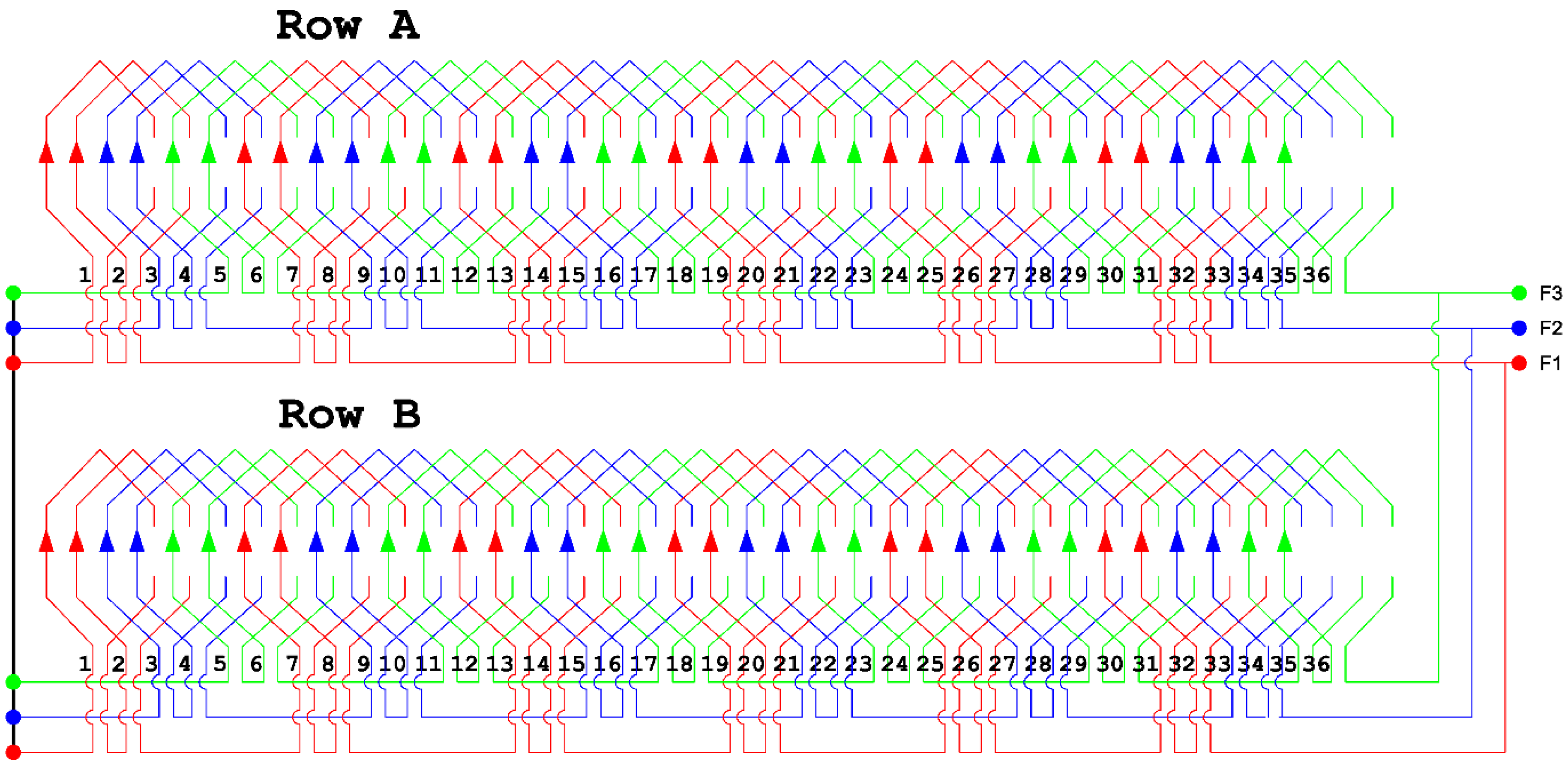
- No-load voltage trends, considering a three-phase connection of coils;
- Magnetic force produced by the interaction of magnets, with the stator in a magneto-static condition.
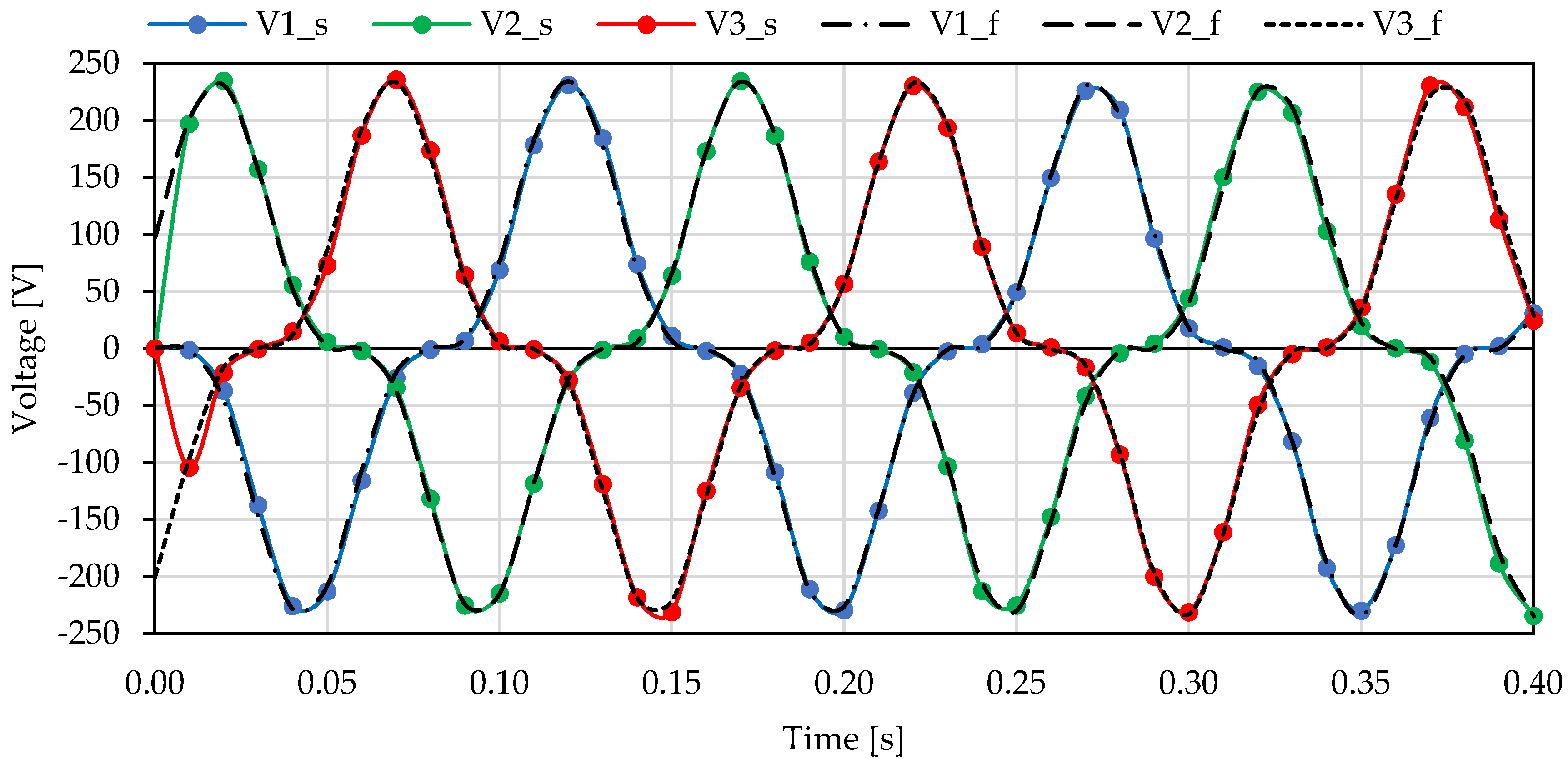
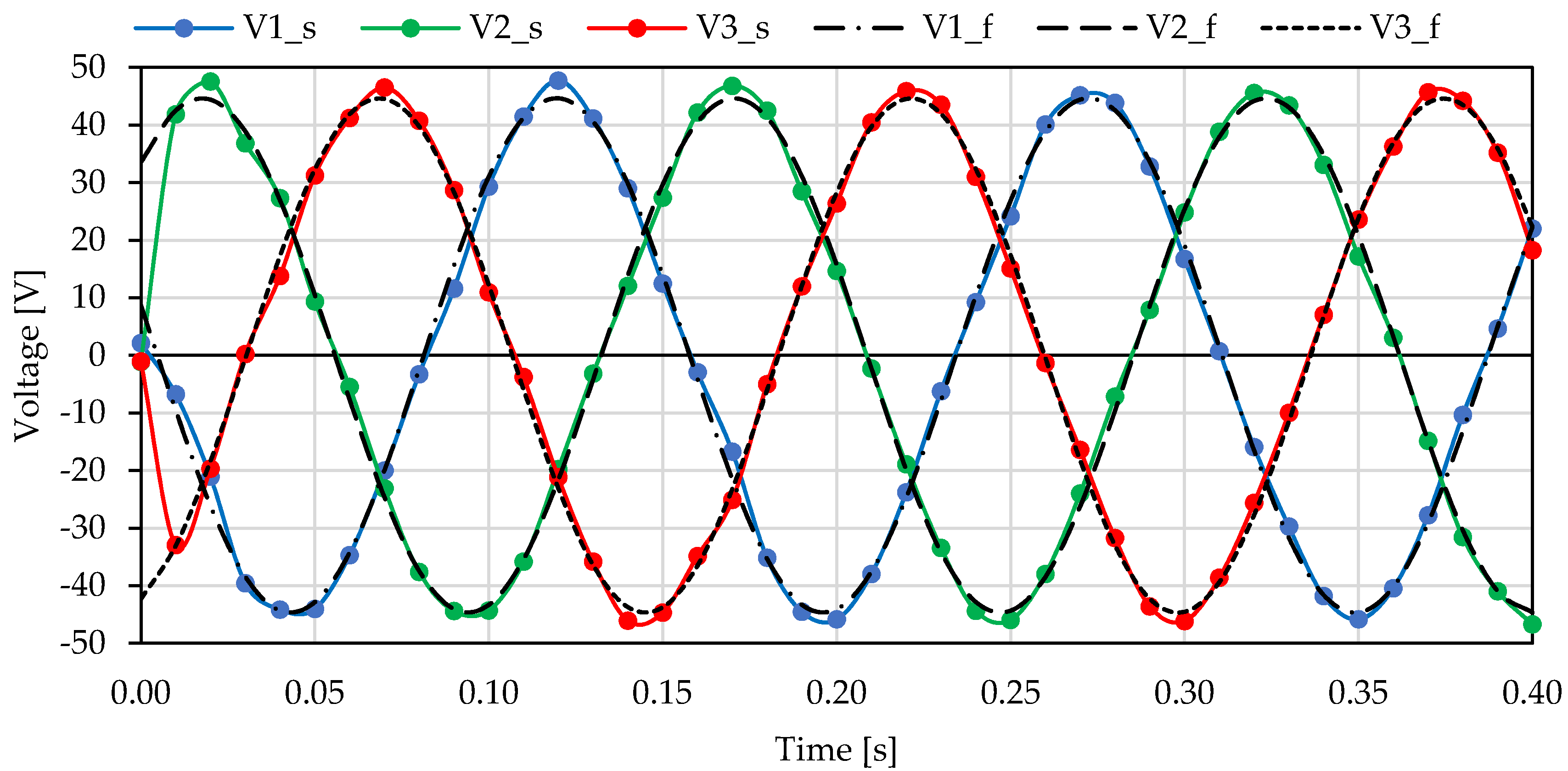
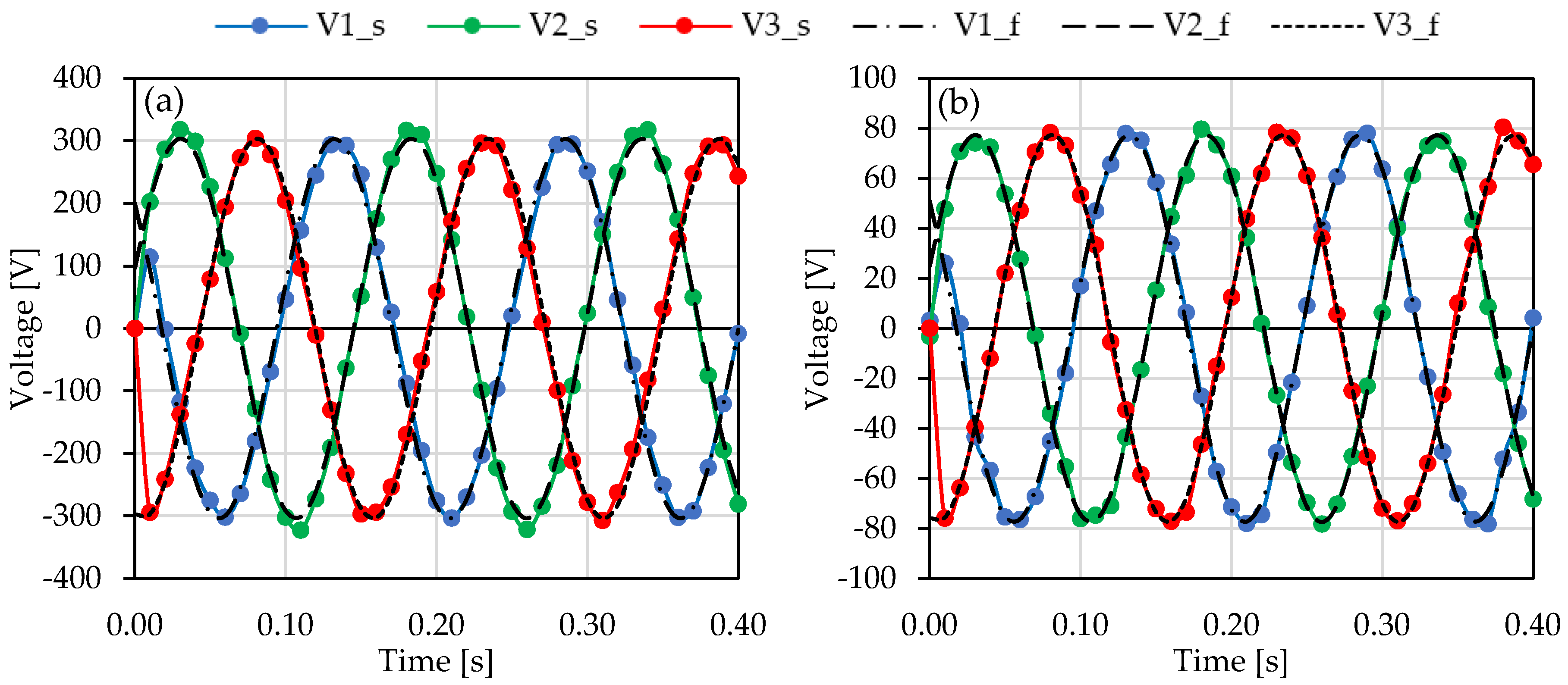
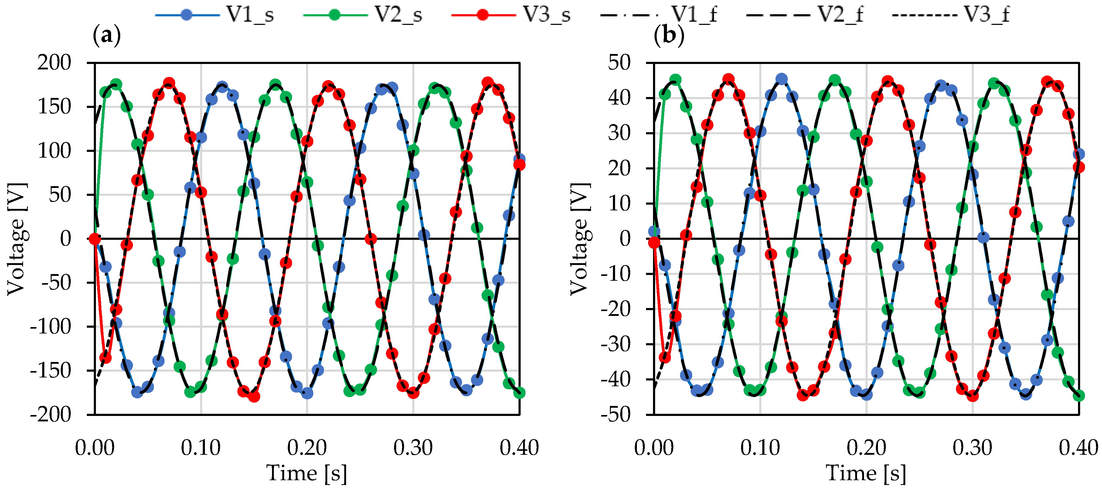
3.1. No-Load Voltages
- Use other schemes of connection for coils;
- Not connect the star center of generator to load.
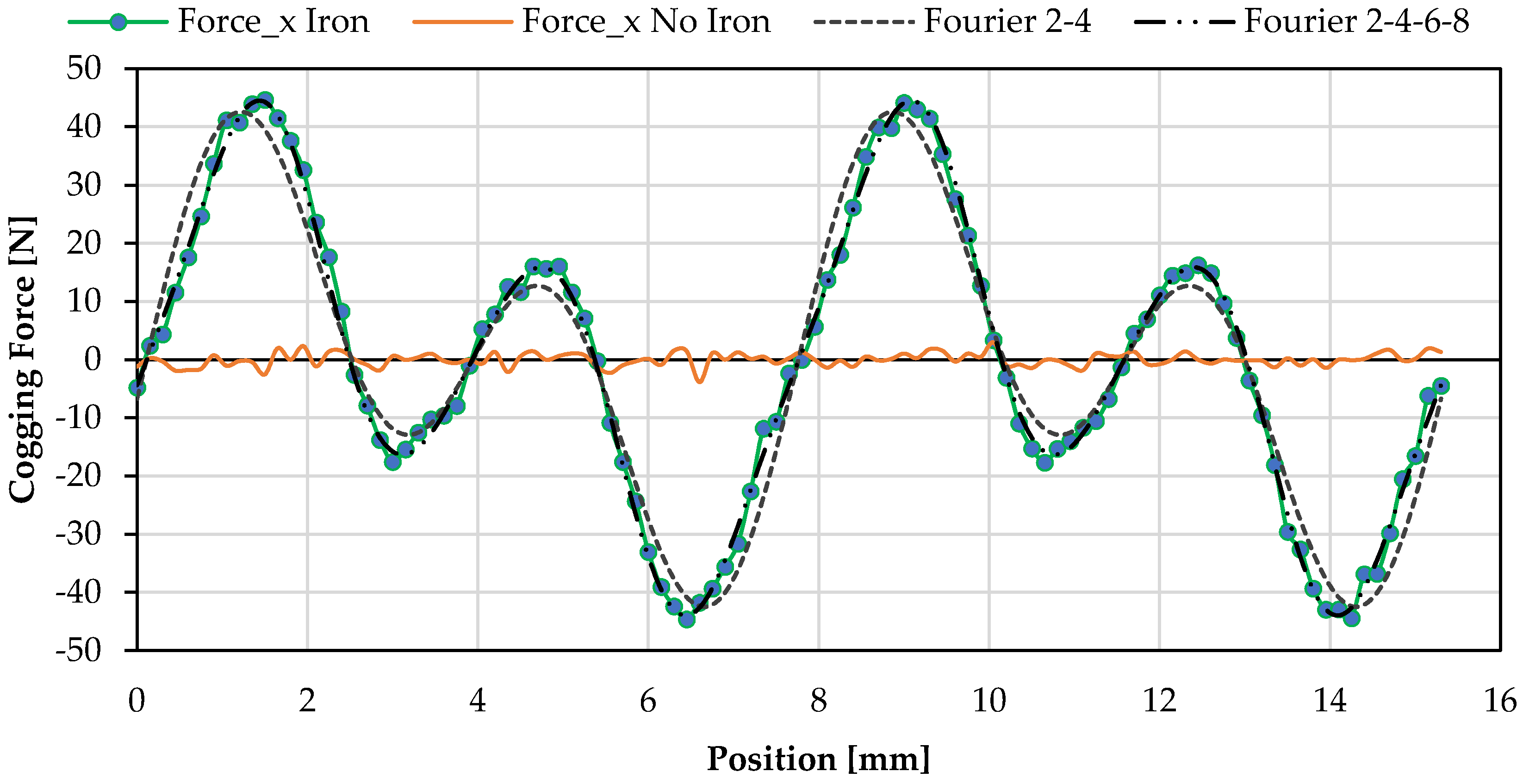
3.2. Cogging Force
- The alternance of tooth and slots in the iron stator;
- The entering and exiting of magnets through the stator region.
- Production of vibration and noise;
- Difficulty to start the system with low values of external force.
4. Conclusions
- Potential weight reduction of the machine;
- Complete removal of the cogging force, increasing the producibility of the electrical energy in sea wave application and drastically reducing the production of vibrations;
- Removal of third harmonic in no-load voltage generation, without changing the connection scheme in the machine.
Author Contributions
Funding
Acknowledgments
Conflicts of Interest
References
- Owusu, P.A.; Asumadu-Sarkodie, S. A review of renewable energy sources, sustainability issues and climate change mitigation. Cogent Eng. 2016, 3, 1–14. [Google Scholar] [CrossRef]
- Sierra, J.P.; Martín, C.; Mösso, C.; Mestres, M.; Jebbad, R. Wave energy potential along the Atlantic coast of Morocco. Renew. Energy 2016, 96, 20–32. [Google Scholar] [CrossRef]
- IEA. Energy and Climate Change; IEA: Paris, France, 2015. [Google Scholar]
- Enerdata Global Energy Statistical Yearbook. 2019. Available online: https://yearbook.enerdata.net/ (accessed on 26 December 2019).
- International Renewable Energy Agency (IRENA). Renewable Capacity Statistics 2019; IRENA: Abu Dhabi, UAE, 2019. [Google Scholar]
- Pelling, M.; Uitto, J.I. Small island developing states: Natural disaster vulnerability and global change. Glob. Environ. Chang. Part B Environ. Hazards 2001, 3, 49–62. [Google Scholar] [CrossRef]
- Rusu, E.; Onea, F. Evaluation of the wind and wave energy along the Caspian Sea. Energy 2013, 50, 1–14. [Google Scholar] [CrossRef]
- World Energy Council. World Energy Council. World Energy Resources. In Marine Energy 2016; World Energy Council: London, UK, 2016; p. 79. [Google Scholar]
- Corsini, A.; Tortora, E.; Cima, E. Preliminary assessment of wave energy use in an off-grid minor island desalination plant. Energy Procedia 2015, 82, 789–796. [Google Scholar] [CrossRef] [Green Version]
- Akar, S.; Akdoğan, D.A. Chapter 13-Environmental and Economic Impacts of Wave Energy: Some Public Policy Recommendations for Implementation in Turkey. In Handbook of Research on Green Economic Development Initiatives and Strategies; IGI Global: Hershey, PA, USA, 2016. [Google Scholar]
- Kalogirou, S.A. Solar Energy Engineering. Processes and Systems, 2nd ed.; Elsevier: Amsterdam, The Netherlands, 2014; ISBN 9780123972705. [Google Scholar]
- Aderinto, T.; Li, H. Ocean Wave energy converters: Status and challenges. Energies 2018, 11, 1250. [Google Scholar] [CrossRef] [Green Version]
- Mork, G.; Barstow, S.; Kabuth, A.; Pontes, M.T. Assessing the Global Wave Energy Potential. In Proceedings of the 29th International Conference on Ocean, Offshore and Arctic Engineering, ASME, Shanghai, China, 6–11 June 2010; Volume 3, pp. 447–454. [Google Scholar]
- Liberti, L.; Carillo, A.; Sannino, G. Wave energy resource assessment in the Mediterranean, the Italian perspective. Renew. Energy 2013, 50, 938–949. [Google Scholar] [CrossRef]
- De Falcão, A.F.O. Wave energy utilization: A review of the technologies. Renew. Sustain. Energy Rev. 2010, 14, 899–918. [Google Scholar] [CrossRef]
- Hong, Y.; Waters, R.; Boström, C.; Eriksson, M.; Engström, J.; Leijon, M. Review on electrical control strategies for wave energy converting systems. Renew. Sustain. Energy Rev. 2014, 31, 329–342. [Google Scholar] [CrossRef]
- Vannucchi, V.; Cappietti, L. Wave Energy Assessment and Performance Estimation of State of the Art Wave Energy Converters in Italian Hotspots. Sustainability 2016, 8, 1300. [Google Scholar] [CrossRef] [Green Version]
- Van Rij, J.; Yu, Y.H.; Guo, Y.; Coe, R.G. A wave energy converter design load case study. J. Mar. Sci. Eng. 2019, 7, 250. [Google Scholar] [CrossRef] [Green Version]
- Heras, P.; Thomas, S.; Kramer, M.; Kofoed, J.P. Numerical and Experimental Modelling of a Wave Energy Converter Pitching in Close Proximity to a Fixed Structure. J. Mar. Sci. Eng. 2019, 7, 218. [Google Scholar] [CrossRef] [Green Version]
- Babarit, A.; Wendt, F.; Yu, Y.H.; Weber, J. Investigation on the energy absorption performance of a fixed-bottom pressure-differential wave energy converter. Appl. Ocean Res. 2017, 65, 90–101. [Google Scholar] [CrossRef] [Green Version]
- Palma, G.; Formentin, S.M.; Zanuttigh, B.; Contestabile, P.; Vicinanza, D. Numerical simulations of the hydraulic performance of a breakwater-integrated overtopping wave energy converter. J. Mar. Sci. Eng. 2019, 7, 38. [Google Scholar] [CrossRef] [Green Version]
- Poguluri, S.K.; Cho, I.H.; Bae, Y.H. A study of the hydrodynamic performance of a pitch-type wave energy converter-rotor. Energies 2019, 12, 842. [Google Scholar] [CrossRef] [Green Version]
- Ji, C.Y.; GUO, Y.C.; Cui, J.; Yuan, Z.M.; Ma, X.J. 3D experimental study on a cylindrical floating breakwater system. Ocean Eng. 2016, 125, 38–50. [Google Scholar] [CrossRef] [Green Version]
- Rusu, E.; Guedes Soares, C. Coastal impact induced by a Pelamis wave farm operating in the Portuguese nearshore. Renew. Energy 2013, 58, 34–49. [Google Scholar] [CrossRef]
- Kurupath, V.; Ekst, R.; Leijon, M. Optimal Constant DC Link Voltage Operation of aWave Energy Converter. Energies 2013, 6, 1993–2006. [Google Scholar] [CrossRef] [Green Version]
- Wacher, A.; Neilsen, K. Mathematical and Numerical Modeling of the AquaBuOY Wave Energy Converter. Math. Case Stud. J. 2010, 2, 16–33. [Google Scholar]
- Polinder, H.; Damen, M.E.C.; Gardner, F. Linear PM Generator System for Wave Energy Conversion in the AWS. IEEE Trans. Energy Convers. 2004, 19, 583–589. [Google Scholar] [CrossRef] [Green Version]
- Bozzi, S.; Archetti, R.; Passoni, G. Wave electricity production in Italian offshore: A preliminary investigation. Renew. Energy 2014, 62, 407–416. [Google Scholar] [CrossRef]
- Colucci, A.; Boscaino, V.; Cipriani, G.; Curto, D.; Di Dio, V.; Franzitta, V.; Trapanese, M.; Viola, A. An inertial system for the production of electricity and hydrogen from sea wave energy. In Proceedings of the OCEANS 2015-MTS/IEEE, Washington, DC, USA, 19–22 October 2015; pp. 1–10. [Google Scholar]
- Raimondi, F.M.; Milone, D.; Curto, D. An innovative mechanical motion converter for sea wave applications. In Proceedings of the 2018 Thirteenth International Conference on Ecological Vehicles and Renewable Energies (EVER) IEEE, Monte-Carlo, Monaco, 10–12 April 2018; pp. 1–6. [Google Scholar]
- Franzitta, V.; Curto, D. Sustainability of the Renewable Energy Extraction Close to the Mediterranean Islands. Energies 2017, 10, 283. [Google Scholar] [CrossRef] [Green Version]
- Atallah, K.; Zhu, Z.Q.; Howe, D. Armature reaction field and winding inductances of slotless permanent-magnet brushless machines. IEEE Trans. Magn. 1998, 34, 3737–3744. [Google Scholar] [CrossRef]
- Abdel-Razek, A.; Coulomb, J.; Feliachi, M.; Sabonnadiere, J. The calculation of electromagnetic torque in saturated electric machines within combined numerical and analytical solutions of the field equations. IEEE Trans. Magn. 1981, 17, 3250–3252. [Google Scholar] [CrossRef]
- Xia, T.; Yu, H.; Shi, Z.; Guo, R. Comparative Analysis and Experimental Verification of a Linear Tubular Generator for Wave Energy Conversion. Energies 2018, 11, 1707. [Google Scholar] [CrossRef] [Green Version]
- Farrok, O.; Islam, M.R.; Sheikh, M.R.I.; Guo, Y.; Zhu, J.G. A Split Translator Secondary Stator Permanent Magnet Linear Generator for Oceanic Wave Energy Conversion. IEEE Trans. Ind. Electron. 2018, 65, 7600–7608. [Google Scholar] [CrossRef]
- Erselcan, İ.Ö.; Kükner, A. A Review of Power Take-Off Systems Employed in Wave Energy Converters. J. Nav. Sci. Eng. 2014, 10, 32–44. [Google Scholar]
- Penalba, M.; Ringwood, J.V. A review of wave-to-wire models for wave energy converters. Energies 2016, 9, 506. [Google Scholar] [CrossRef] [Green Version]
- Li, B.; Macpherson, D.E.; Shek, J.K.H. Direct drive wave energy converter control in irregular waves. In Proceedings of the IET Conference on Renewable Power Generation (RPG 2011) IET, Edinburgh, UK, 6–8 September 2011; p. 64. [Google Scholar]
- Poullikkas, A. Technology Prospects of Wave Power Systems. Electron. J. Energy Environ. 2014, 2, 47–69. [Google Scholar]
- Arof, H.; Nor, W.; Nor, K.M. Linear generator: Design and simulation. In Proceedings of the National Power Engineering Conference IEEE, Bangi, Malaysia, 15–16 December 2003; pp. 306–311. [Google Scholar]
- Faiz, J.; Nematsaberi, A. Linear electrical generator topologies for direct-drive marine wave energy conversion- an overview. IET Renew. Power Gener. 2017, 11, 1163–1176. [Google Scholar] [CrossRef]
- Boldea, I.; Nasar, S.A. Linear Electric Actuators and Generators, 1st ed.; Cambridge University Press: Cambridge, UK, 1997; ISBN 9780521480178. [Google Scholar]
- Rao, K.S.R.; Sunderan, T.; Ref, M. Performance and design optimization of two model based wave energy permanent magnet linear generators. Renew. Energy 2017, 101, 196–203. [Google Scholar] [CrossRef]
- Zhang, G.; Yu, W.; Hua, W.; Cao, R.; Qiu, H.; Guo, A. The Design and Optimization of an Interior, Permanent Magnet Synchronous Machine Applied in an Electric Traction Vehicle Requiring a Low Torque Ripple. Appl. Sci. 2019, 9, 3634. [Google Scholar] [CrossRef] [Green Version]
- García-Gracia, M.; Jiménez Romero, Á.; Herrero Ciudad, J.; Martín Arroyo, S. Cogging Torque Reduction Based on a New Pre-Slot Technique for a Small Wind Generator. Energies 2018, 11, 3219. [Google Scholar] [CrossRef] [Green Version]
- Arehpanahi, M.; Kashe, H. Cogging torque reduction of Interior Permanent Magnet Synchronous Motor (IPMSM). Sci. Iran. 2018, 25, 1471–1477. [Google Scholar] [CrossRef] [Green Version]
- Islam, M.S.; Mir, S.; Sebastian, T. Issues in Reducing the Cogging Torque of Mass-Produced Permanent-Magnet Brushless DC Motor. IEEE Trans. Ind. Appl. 2004, 40, 813–820. [Google Scholar] [CrossRef]
- Awah, C.C.; Okoro, O.I.; Chikuni, E. Cogging torque and torque ripple analysis of permanent magnet flux-switching machine having two stators. Arch. Electr. Eng. 2019, 68, 115–133. [Google Scholar]
- Shabani, M.A.; Milimonfared, J.; Taghipour, S. Cogging force mitigation of tubular permanent magnet machines with magnet dividing. In Proceedings of the 2007 International Conference on Electrical Machines and Systems (ICEMS), Seoul, Korea, 8–11 October 2007; pp. 810–814. [Google Scholar]
- Wang, Q.; Zhao, B.; Zou, J.; Li, Y. Minimization of cogging force in fractional-slot permanent magnet linear motors with double-layer concentrated windings. Energies 2016, 9, 918. [Google Scholar] [CrossRef] [Green Version]
- Zhou, S.; Yu, H.; Hu, M.; Jiang, C.; Hao, L. Reduction of cogging force in a linear flux-switching permanent-magnet brushless AC machine for direct-drive applications. IEEE Trans. Magn. 2011, 47, 3252–3255. [Google Scholar] [CrossRef]
- Huang, W.; Shi, C.; Xue, Y.; Song, G.; Ling, Y. Optimal design of Permanent Magnet Linear Motor for reducing cogging force. In Proceedings of the 2014 IEEE Conference and Expo Transportation Electrification Asia-Pacific (ITEC Asia-Pacific), Beijing, China, 31 August–3 September 2014; pp. 1–4. [Google Scholar]
- Franzitta, V.; Catrini, P.; Curto, D. Wave Energy Assessment along Sicilian Coastline, Based on DEIM Point Absorber. Energies 2017, 10, 376. [Google Scholar] [CrossRef] [Green Version]
- Trapanese, M.; Boscaino, V.; Cipriani, G.; Curto, D.; Di Dio, V.; Franzitta, V. A Permanent Magnet Linear Generator for the Enhancement of the Reliability of a Wave Energy Conversion System. IEEE Trans. Ind. Electron. 2018, 0046, 1. [Google Scholar] [CrossRef]
- Curto, D. Ottimizzazione Delle Performances Energetiche di un innovativo Generatore di Energia Elettrica da Moto Ondoso; Gruppo Editoriale L’Espresso: Rome, Italia, 2014. [Google Scholar]
- Supermagnete. Available online: https://www.supermagnete.it/eng/data_sheet_Q-60-30-15-N.pdf (accessed on 3 February 2020).
- Monk, P. Finite Element Methods for Maxwell’s Equations; Oxford University Press: Oxford, UK, 2003; ISBN 9780198508885. [Google Scholar]
- Trapanese, M.; Cipriani, G.; Curto, D.; Di Dio, V.; Franzitta, V. Optimization of cogging force in a linear permanent magnet generator for the conversion of sea waves energy. In Proceedings of the 2015 IEEE International Electric Machines & Drives Conference (IEMDC) IEEE, Coeur d’Alene, ID, USA, 10–13 May 2015; pp. 769–773. [Google Scholar]


| Article ID. | Q60-30-15-N | 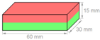 |
| Material | NdFeB | |
| Shape | block | |
| Size | 60 × 30 × 15 mm | |
| Pole faces | 60 × 30 mm | |
| Tolerance | ±0.1 mm | |
| Coating | Nickel-plated (Ni-Cu-Ni) | |
| Manufacturing method | Sintered | |
| Direction of magnetization | Axis 15 mm | |
| Magnetization | N40 | |
| Strength | Approx. 56 kg (549 N) | |
| Max working temperature | 80 °C | |
| Curie temperature | 310 °C | |
| Weight | 205.2 g | |
| Residual magnetism Br | 12,600–12,900 G, 1026–1.29 T | |
| Coercive field strength bHc | 10.5–12.0 kOe, 860–955 kA/m | |
| Coercive field strength iHc | ≥12 kOe, ≥955 kA/m | |
| Energy product (BxH)max | 38–40 MGOe, 303–318 kJ/m3 |
| Parameter | Symbol | Value | Unit |
|---|---|---|---|
| First harmonic amplitude | 175.24 | V | |
| Third harmonic amplitude | 59.24 | V | |
| First harmonic phase | 2.941 | rad | |
| Third harmonic phase | −0.607 | rad | |
| Angular frequency | 41.07 | rad/s |
| Parameter | Symbol | Value | Unit |
|---|---|---|---|
| First harmonic amplitude | 44.65 | V | |
| First harmonic phase | 2.946 | rad | |
| Angular frequency | 41.07 | rad/s |
| Order | Amplitude [N] | Phase [rad] |
|---|---|---|
| 0 | 0.064 | - |
| 1 | 0.681 | 0.1892 |
| 2 | 21.234 | −0.0864 |
| 3 | 0.312 | −1.0273 |
| 4 | 26.587 | −0.1833 |
| 5 | 0.641 | 3.1637 |
| 6 | 5.316 | 2.9119 |
| 7 | 0.151 | 2.6296 |
| 8 | 3.128 | 2.7715 |
| 9 | 0.208 | 0.1307 |
| 10 | 0.208 | 2.7913 |
© 2020 by the authors. Licensee MDPI, Basel, Switzerland. This article is an open access article distributed under the terms and conditions of the Creative Commons Attribution (CC BY) license (http://creativecommons.org/licenses/by/4.0/).
Share and Cite
Curto, D.; Viola, A.; Franzitta, V.; Trapanese, M.; Cardona, F. A New Solution for Sea Wave Energy Harvesting, the Proposal of an Ironless Linear Generator. J. Mar. Sci. Eng. 2020, 8, 93. https://doi.org/10.3390/jmse8020093
Curto D, Viola A, Franzitta V, Trapanese M, Cardona F. A New Solution for Sea Wave Energy Harvesting, the Proposal of an Ironless Linear Generator. Journal of Marine Science and Engineering. 2020; 8(2):93. https://doi.org/10.3390/jmse8020093
Chicago/Turabian StyleCurto, Domenico, Alessia Viola, Vincenzo Franzitta, Marco Trapanese, and Fabio Cardona. 2020. "A New Solution for Sea Wave Energy Harvesting, the Proposal of an Ironless Linear Generator" Journal of Marine Science and Engineering 8, no. 2: 93. https://doi.org/10.3390/jmse8020093