Article

Hydrodynamic Load Analysis and Experimental Study of Grouting Clamp under Wave and Ocean Current

1
College of Mechanical and Electrical Engineering, Harbin Engineering University, Harbin 150001, China
2
School of Mechanical Engineering, Hebei University of Technology, Tianjin 300401, China
*
Author to whom correspondence should be addressed.
J. Mar. Sci. Eng. 2020, 8(7), 512; https://doi.org/10.3390/jmse8070512
Submission received: 29 April 2020 / Revised: 31 May 2020 / Accepted: 28 June 2020 / Published: 13 July 2020
(This article belongs to the Section Ocean Engineering)

Abstract

:
The repair of offshore platform jackets is an important research direction in marine engineering, among which the grouting clamp reinforcement is the most widely used. In order to solve the hydrodynamic force of the grouting hoop under the joint action of wave and current in the complex sea condition, the Morison formula is used to analyze the linear wave load on the grouting hoop; then, based on the Morison formula, load force under the combined action of the wave and the ocean current on the clamps in different installation states was determined; finally, the screw jack and car jack were used to carry out the experiment of preventing the clamp from falling off. The mechanical grouting clamp experiment and the wedge tooth experiment were carried out at the same time. The innovative design of the mechanical grouting clamp, analyzed analogously through relevant experimental results and numerical analysis results confirmed that the reinforcement and repair method of the designed grouting clamp is of great help to the safety and reliability of the offshore platform jacket.

1. Introduction

The jacket offshore platform is the most widely used of steel pile foundation platforms and is used in major bays around the world. The offshore platform of the jacket will be affected by the severe and harsh marine environment such as sea breeze and current. Once it is damaged, the loss is huge, so it puts higher engineering requirements and safety challenges on the jacket offshore platform. As a device for reinforcing and repairing offshore platforms, grouting clamps are also subject to loads from the ocean, mainly wave loads and current loads [1].

1.1. Current Status of Clamp Research

In the past 30 years abroad, the United States, the Netherlands, Norway, the United Kingdom and other countries have carried out a lot of research on the repair and reinforcement technology of damaged structures on offshore platforms. Through theoretical analysis, the grouting clamp repair and reinforcement technology have been maturely used in marine engineering. These achieved a rapid development trend.
In the 1980s, the team of Professor Elnashai AS conducted a mechanical experiment of pressure grouting clamps, using high-pressure grouting to inject cement slurry between the clamp and the damaged structure to obtain the expansion pressure. Used in large-scale model experiments, applying data from small-scale experiments to design a series of large-scale models. This series of experiments confirmed that the results of small-scale experiments and computer calculations can be applied to all models [2]. In 1989, the British Shuttleworth et al. summarized the repair and reinforcement methods of the partially damaged components of more than 60 types of offshore platforms in the world, and selected the advanced maintenance and reinforcement methods at that time: welding repair method, clamp repair solid method and sanding repair method [3]. In 2015, Australia Advanced Composite Structure Co., Ltd. and National Petroleum Corporation of Malaysia developed polymer composite clamps, designed with different thicknesses of sandwich laminates, gaps between pipes and clamps, rubber seal hardness and test temperature. The test results show that the composite material clamp has a margin to withstand the design pressure. Generally speaking, the leakage sealing capacity of the composite material clamp increases with the increase of the thickness and the increase of the seal hardness, and decreases with the increase of the gap small. Finally, the results successfully proved the design method of these composite clamps [4]. In 2016, Sum W S, Leong K H and others proposed a new method of repairing leaking or other damaged metal pipes using composite material clamps. This method uses a uniquely designed resin injected into the composite clamp. Significant improvements to commercial metal clamps have achieved light weight and corrosion resistance [5]. In 2018, Gunnar Solland and Atle Johansen and others summarized the current design rules of grouting pile-sleeve connection, and conducted compression and tensile axial load experiments on the grouting clamps, respectively, and proposed a new design formula [6]. In 2019, Nikolaos I. Tziavos tested the structural performance of the grouted offshore wind turbine mechanism under large bending moment [7].
In China, the research on grouting clamp repair technology started relatively late. Since the 1990s, many scholars in China have begun to pay attention to the research of grouting clamp repair technology, but for applying grout clamp to the actual offshore platform jacket repair there are fewer examples. In 2001, Gong Shunfeng and others studied the maintenance and reinforcement of offshore steel structures on the basis of referring to the literatures of various countries in the world and thoroughly studied the grouting clamps of T-shaped pipe joints. The model is through the axial tension, compression and in-plane bending moment of the T-tube joint grouting clamp [8]. In 2016, Engineer Zhang Yong and others used the tension grouting clamp to repair the cracks at the cross diagonal brace of the HZ21-1A jacket platform deep in the seabed. After conducting the land strength test and filling test, the results show that the tension grouting clamp is the best to repair the X-bracket crack of the jacket. This invention also provides a strong technical reference for similar grouting work in the future [9]. In 2019, Shi Xiang and others tested the bearing capacity of actual size self-stressed grouting clamps for marine applications, and conducted laboratory and offshore experimental studies on the two clamp models, measured their expansion pressure and sliding stress, and placed After several days of underwater maintenance, it is taken up to test the sliding bearing capacity to verify the underwater bearing performance, which is beneficial to the practical engineering application of the clamp technology [10].
It can be seen from the above literature that in the past 30 years, countries around the world have made a lot of contributions to the research of grouting clamping, mainly in the pressure grouting clamp mechanics experiment, the expansion pressure is obtained [2]; compare various maintenance methods and select the most suitable reinforcement method [3]; verification of the feasibility of using advanced composite clamps for repair methods [4,5]; summarize the design rules of grouting clamp repair and propose a new design formula [6]. The main contribution in China is to study the T-tube joint grouting clamp [7]; crack repair using tensioned grouting clamps [8]; carrying capacity test of self-stress grouting clamps [9]; bearing capacity test of self-stressing grouting clamp [10]. The above literature has played a certain reference role in the analysis of hydrodynamic loads subjected to this grouting clamp.

1.2. Research Status of Water Wave Theory

Countries around the world have been studying water wave theory for a long time, and put forward a series of formulas with important reference value. In 2002, BOO of the Korean Naval Academy studied the regular wave and irregular wave problem by high-order boundary element method and simulated the load, and studied the diffraction problem of the wave [11]. In 2015, Guido Lupieri, a professor of engineering and architecture at the University of Trieste in Italy, numerically modeled the two-dimensional steady-state and non-steady state of the fracture wave [12]. In 2018, Robin Ming Chen studied the existence and qualitative theory of layered solitary waves [13]. In 2019, khait and shemer studied a different harmonic separation method in large-scale experimental equipment. The application of all non-linear numerical wave boxes make the experimental work minimized. The applicability of the iterative method in deep water is proved [14].
China’s research on water wave theory started late compared with other countries in the world. In 2000, Ma Wei and Li Guixi analyzed the spectral characteristics of second-order Stokes random waves using theoretical methods and numerical methods. By introducing the Hermite polynomial, the relationship between the wavefront Equation and the autocorrelation function of the first-order component is obtained, and then the wave spectral density of the second-order Stokes is obtained [15]. In 2011, Chen Xiaobo of Dalian University of Technology used the flow function to calculate the magnitude of the wave force in the case of 10th order, and compared with the linear theory, it was found that the wave force calculated by the linear theory is too small [16]. In 2016, Tian Xiaohuan of Dalian University of Technology and others simulated the wave based on second-order theory in the laboratory sink. Verification of the effectiveness of the second-order is the wave-making method [17]. In 2019, at the 30th national hydrodynamics research conference, Huang Dongwei and others proposed the numerical simulation of shallow water wave breaking based on displacement method, and deduced the two-dimensional shallow water wave breaking term in the Lagrange coordinate system [18].
It can be concluded from the above literature that the wave is a stochastic process, and it is difficult to analyze it accurately. The study of waves in various countries in the world ranges from simple to complex. Linear wave theory, finite wave amplitude theory, elliptic curve describe wave, and effective wave theory has made outstanding contributions in the study of water wave theory [11,12,13,14]. The wave period distribution function is proposed; the load simulation calculation is performed on the regular wave and the irregular wave; the two-dimensional steady state and the non-steady state of the breaking wave are numerically modeled; the existence and qualitative theory of the layered solitary wave are studied; Calculate the second-order Stokes wave spectral density; calculate the wave force in the 10th order; the above is a supplementary study of the water wave theory [18,19,20,21].
In summary, at present, each research is mainly aimed at the analysis of the bearing capacity of the grouting clamp in the jacket. For the grouting clamping under the action of wave load and current load, there is little research on the anti-tripping performance.
The method used in this article is: first, the installation position of the clamp on the offshore platform is divided into two types: vertical installation and horizontal installation; then we use Morison to calculate the force on the clamp under the combined action of the waves and ocean currents under these two installation forms, so as to calculate the maximum force on the clamp; finally, the wedge tooth experiment, mechanical grouting clamp experiment and mechanical grouting clamp slip-off force experiment are used to verify whether the designed structure can withstand the forces under the combined action of waves and ocean currents.
The experimental results are: the mechanical clamp experiment proves that the designed structure has a very effective effect on repairing damaged structures; the wedge tooth test and mechanical grouting clamp slip force test verify that the designed structure can withstand the forces under the common action of waves and currents on the sea. That is, the innovative design of the mechanical clamp has great practical significance for the repair of offshore platform ducts.

2. Hydrodynamic Load Analysis and Calculation of Clamp

2.1. Linear Wave Motion Characteristics

Figure 1 shows a simplified diagram of wave propagation, with the forward direction forward and the ocean depth d. Suppose the wave is an ideal fluid, namely: the fluid is non-sticky and the fluid moves with potential; the external force is only affected by gravity; the pressure p at the fluid is consistent with the atmospheric pressure; The bottom of the sea is a horizontal solid boundary; compared with the wavelength, the amplitude and height of the wave can be regarded as infinitely small, and the moving speed of the wave water is slow. When the wave is propagating forward, it is doing sinusoidal movement, and its shape remains unchanged. It can ignore the nonlinear factors of the wave free surface, so the nonlinear boundary conditions in the working sea area can be converted into linear boundary conditions. The wave theory that satisfies the above assumptions is the linear wave theory.
In Figure 1, the height difference between any peak and its adjacent trough is the wave height, H. The wavelength is the horizontal distance L between any point on the wave surface and the corresponding point on the subsequent waveform. The time T required observing a complete waveform through a fixed position is the wave period. The speed of wave propagation is also called phase velocity, which is c = L / T . The parameters of the wave are the circle frequency ω = 2 π / T and the wave number k = 2 π / L . After determining the three parameters H, L (or T) and d, the waveform of any wave can be determined. Its hydrodynamic characteristics can be derived from the wave theory. Set the velocity potential of the ideal fluid to Φ . Φ is the position and time function of any point in the coordinate system. Record as: Φ ( x , z , t ) . Φ satisfies the Laplace Equation:
2 Φ x 2 + 2 Φ z 2 = 0
The boundary conditions are:
At the sea floor wall z = −d, the velocity in the vertical direction is zero:
Φ z | z = d = 0
The water mass has a velocity at the free surface of the wave, which is perpendicular to the free surface of the wave:
η t + Φ x η x Φ z = 0 , ( z = η )
The atmospheric pressure at the wave surface is fixed:
Φ t + 1 2 [ ( Φ x ) 2 + ( Φ z ) 2 ] + g η = f ( t ) , ( z = η )
Periodic conditions of waves:
Φ ( x , z , t ) = Φ ( x c t , z )
When the wave height H of the wave is small enough, then at the middle height of the wave at z = 0, Equations (3) and (4) can be approximately established. In this case, η is infinitesimal, its related terms are negligible and the power term related to amplitude is also negligible. With the above conditions, the equation can be linearized, and then the boundary conditions at the free surface can be expressed as follows:
η t Φ z = 0 , ( z = 0 )
Φ t + g η = 0 , ( z = 0 )
Available from (6) and (7):
2 Φ t 2 + g Φ z = 0 , ( z = 0 )
Using the separation variable method, Φ can be written as follows:
η = 1 g Φ t | z = 0
Φ = Z ( z ) Φ ( x c t )
Substituting it into the Laplace Equation, we get:
Φ ( x c t ) Z ( z ) + Z ( z ) Φ ( x c t ) = 0
Or
Φ ( x c t ) Φ ( x c t ) = Z ( z ) Z ( z ) = k 2
k is the coefficient to be determined. From Equation (12), two differential equations can be obtained:
Z ( z ) k 2 Z ( z ) = 0
Φ ( x c t ) = k 2 Φ ( x c t ) = 0
The general solution is:
Z ( z ) = A 1 ch ( k z ) + A 2 sh ( k z )
Φ ( x c t ) = A 3 cos [ k ( x c t ) ] + A 4 sin [ k ( x c t ) ]
In the formula, A 1 , A 2 , A 3 , A 4 are the integral constants, which can be determined by the boundary conditions. Suppose that when the wave crest passes x = 0 and the starting moment t = 0 , the velocity potential is obtained after solving the integration constant:
Φ = g H 2 k c c h [ k ( z + d ) ] s h ( k d ) sin [ k ( x c t ) ]
In the formula, wavelength L = 2 π / k , cycle T = 2 π / k c = 2 π / ω . The wave number can be set to a constant k, k c = ω , ω is the circle frequency, c = L / T = ω / k is the wave speed. In addition, ω 2 = k g tanh ( k d ) can be obtained from the theory of velocity potential. The relationship between the main parameters of the limited water depth wave can then be derived, the period, wavelength and wave speed are as follows:
c = g T 2 π tanh ( k d )
T = 2 π L g cosh ( k d )
L = g T 2 2 π tanh ( k d )
According to the theory of velocity potential, the velocity of the wave water mass can be obtained (The following formula k x ω t replaces k ( x c t ) ). The horizontal and vertical velocities are shown in Equations (21) and (22), respectively:
u x = Φ x = π H T ch [ k ( z + d ) ] sh ( k d ) cos ( k x ω t )
u z = Φ z = π H T sh [ k ( z + d ) ] sh ( k d ) sin ( k x ω t )
At the same time, the acceleration of the wave water mass can be calculated; the horizontal and vertical motion accelerations are shown in Equations (23) and (24), respectively:
d u x d t = 2 π 2 H T 2 ch [ k ( z + d ) ] sh ( k d ) sin ( k x ω t )
d u z d t = 2 π 2 H T 2 sh [ k ( z + d ) ] sh ( k d ) cos ( k x ω t )
In order to facilitate the calculation, the waves are simplified and regular waves are used for calculation. The regular wave height is set at 1.5 m, the wave period is 10 s and the wavelength is 150 m. According to formulas (21)–(24), the velocity and acceleration of water quality points at different water depths can be obtained, as shown in Figure 2 and Figure 3. It can be seen from Figure 2 that under wave conditions, the maximum horizontal velocity of water quality points decreases with increasing water depth, and the maximum value is obtained at sea level. When the water depth exceeds half the wavelength, the maximum horizontal velocity of the water quality point is almost zero. As can be seen in Figure 3, the maximum horizontal acceleration of water quality points is consistent with the horizontal velocity in the vertical direction, and both decrease with increasing water depth. Therefore, it can be obtained that the wave force that the clamp is subjected to at the water surface position is the largest.

2.2. The Stress on the Hoop under the Joint Action of Wave and Current

In the process of wave propagation, the wave will be accompanied by the flow of water. When wave and current exist together, they will interact with each other and influence each other’s propagation. Wave will refract and the current velocity will change. The following is an analysis of the wave field formed by regular waves. The installation position of grouting clamp is shown in Figure 4. The part 1 is vertical clamp and the part 2 and part 3 are horizontal clamps [22].

2.2.1. Grouting Clamp on Vertical Steel Pipe

According to the Morison equation, the drag force f D is mainly determined by the horizontal speed of the water quality point, the stress analysis diagram of clamp is shown in Figure 5. When the speed of the water quality point is changing, an inertia force f I will be generated on the clamp.
d F H = ( f D + f I ) d z = 1 2 C D ρ D u x | u x | d z + C M ρ π D 2 4 u x t d z
where, u x is the horizontal velocity of water quality point under the comprehensive action of wave and current, u x / t is the horizontal acceleration of water quality point under the comprehensive action of wave and current, C D is the drag force coefficient, C M is the inertia force coefficient [23], D is the outer diameter of grouting clamp and ρ is the density of sea water.
According to the Morison equation, the vertical wave force of grouting clamp on vertical steel pipe can be obtained as follows:
d f v = 1 2 C f ρ u z | u z | d z + C M ρ π D 2 4 u z t d z
where, u z is the vertical velocity of water quality point under the comprehensive action of wave and current; u z / t is the vertical acceleration of water quality point under the comprehensive action of wave and current; C f is the friction coefficient, taking 0.1.
Assuming that the vertical steel pipe pile is subjected to wave current force in the same direction, the wave is designed in a period of 50 years, as shown in the Table 1.
According to the regulations of American Petroleum Institute, in the case of pure current (i.e., without wave propagation), the current force C f on the unit length of grouting clamp is:
f c = 1 2 ρ C D D u c | u c |
In the formula:
ρ —sea water density, kg/m3;
u c —vector component of current velocity perpendicular to the projection surface, m/s.
The horizontal wave current force and vertical wave current force of the vertically installed clamp are:
F H = z 1 z 2 f H d z = C D ρ g D H 2 2 K 1 cos θ | cos θ | + C M ρ g π D 2 H 8 K 2 sin θ + 1 2 ρ C D D u c 2 ( z 2 z 1 )
F V = z 1 z 2 f v d z = z 1 z 2 ( 1 2 C f ρ D u z | u z | + C M ρ π D 2 4 u z t ) d z = 1 2 C f ρ π 2 H 2 D T 2 sh 2 ( k d ) K 3 sin θ | sin θ | + C M ρ D 2 π 3 H 2 T 2 sh ( k d ) K 4 cos θ
The values of K 1 , K 2 , K 3 and K 4 are as follows:
K 1 = 2 k ( z 2 z 1 ) + sinh ( 2 k z 2 ) sinh ( 2 k z 1 ) 8 sinh ( 2 k d )
K 2 = sinh ( k z 2 ) sinh ( k z 1 ) cosh ( k d )
K 3 = 2 k ( z 1 z 2 ) + sinh ( 2 k z 2 ) sinh ( 2 k z 1 ) 4 k
K 4 = cosh ( k z 2 ) cosh ( k z 1 ) k
In this paper, the depth of the pile d = 250   m , current speed u c = 0.6   m / s . These two parameters are set by oneself according to actual experience, the current velocity, the outer diameter of the clamp is 3.45 m, the length is 3.8 m, the diameter of the steel pipe is 1.8 m. Other relevant parameters are shown in Table 1. As shown in Figure 6, the horizontal velocity of water quality point changes with phase angle and water depth. Figure 6 shows the change of vertical wave current force (i.e., hoop axial force) with water depth and phase angle; and its change is the same as the horizontal wave current. When the water depth is less than 200 m, the axial wave current force is 0 and does not change with the phase angle. When the water depth is greater than 200 m, the wave current force is greatly affected by the period, and presents periodic oscillation with the change of phase angle. The maximum wave current force at the level of clamp is 0.82 × 10⁵ kN, and the maximum wave current force at the radial direction of clamp is 0.64 × 10⁵ kN.
Figure 7a,b below shows the change of horizontal wave current force (i.e., hoop radial force) with water depth and wavelength, and the change of vertical wave current force (i.e., hoop axial force) with water depth and wavelength. At this time, the phase angle is 45°.
When the water depth is less than 200 m, the value of axial wave current force is 0 and does not change with the change of wavelength. When the water depth is more than 200 m, the wave current force is greatly affected by the wavelength, and it increases exponentially with the wavelength change. The maximum horizontal wave current force is 12.1 × 10⁴ kN, and the maximum vertical wave current force is 9 × 10⁴ kN. Between 230 m and 250 m, the wave current force decreases with the increase of wavelength.

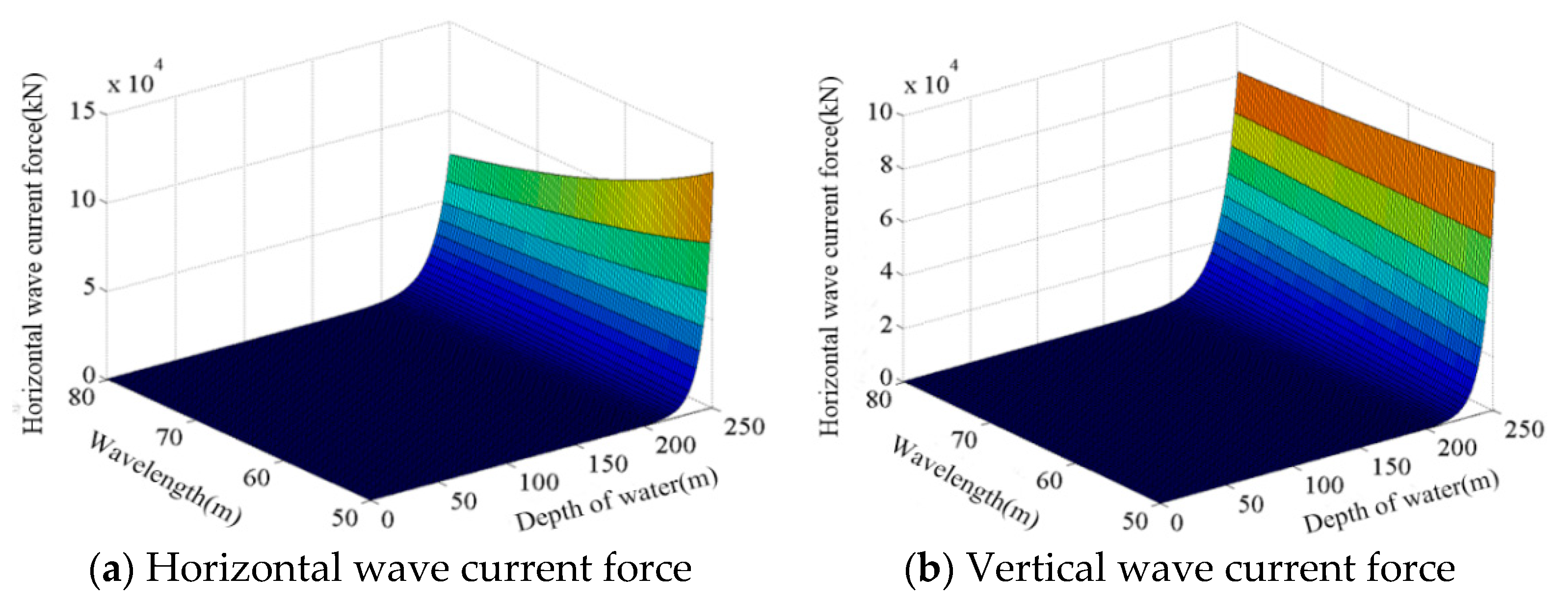
2.2.2. Grouting Clamp on Horizontal Steel Pipe (The Direction of Wave Flow Is the Radial Direction of Clamp)

When the clamp placed horizontally and the wave current direction is the radial direction of the clamp, the upper pressure will be smaller than the lower pressure to form a pressure difference, and the wave and current will generate a lift on the clamp in the radial direction, as shown in Figure 8.
For horizontally installed clamps, when the wave current direction is radial, the horizontal wave current force is:
F H = z 1 z 2 f H d z = z 1 z 2 ( 1 2 C D ρ D u x | u x | + C M ρ π D 2 4 u x t + 1 2 ρ C D D u c | u c | ) d z = C D ρ g D H 2 2 K 1 cos θ | cos θ | + C M ρ g π D 2 H 8 K 2 sin θ + 1 2 ρ C D D u c 2 ( z 2 z 1 )
For horizontally installed clamps, when the wave current direction is radial, the vertical wave current force is:
F V = z 1 z 2 f V d z = z 1 z 2 ( 1 2 C D D ρ u z | u z | + C M ρ π D 2 4 u z t + 1 2 C L ρ D u x 2 ) d z = 1 2 C D ρ π 2 H 2 D T 2 sh 2 ( k d ) K 3 sin θ | sin θ | + C M ρ D 2 π 3 H 2 T 2 sh ( k d ) K 4 cos θ + C L ρ g D H 2 2 K 1
In the formula: C L —lift coefficient, 0.3.
The following figure shows the change of horizontal wave current force with water depth and phase angle, and the change of vertical wave current force with water depth and phase angle. The change rule of Figure 9a,b above is consistent with that of Figure 3. The maximum horizontal wave current force (maximum radial force) of the clamp is 0.85 × 10⁵ kN, and the maximum vertical wave current force (maximum lifting force) of the clamp is 7 × 10⁴ kN.
At this time, the horizontal wave current force of the clamp is greater than the vertical wave current force, and the horizontal wave current force formed by the direct impact of water quality points on the surface is greater than the lift force due to the pressure difference between the upper and lower. The change rule of Figure 10a,b below is consistent with Figure 10a,b. The maximum horizontal wave current force is 14.8 × 10⁴ kN, and the maximum vertical wave current force is 9 × 10⁴ kN. Between 230 m and 250 m, the wave current force decreases with the increase of wavelength.

3. Experimental Data Analysis of Mechanical Grouting Clamp

3.1. Experimental Method of Mechanical Grouting Clamp

3.1.1. Equipment Composition

The grouting clamp used in this time is different from the traditional one, and a self-locking mechanism is used in the grouting ring [24,25,26]. The mechanism adopts inclined plane self-locking, uses dovetail groove as guide, and selects tooth shape surface at the bottom of wedge to contact with defective steel pipe to increase friction coefficient. The selection of grouting mechanical clamp not only retains the advantages of traditional grouting clamp, but also increases the self-locking performance. Even if the grouting material fails, the self-locking mechanism can ensure the safety of the grouting clamp, and the self-locking mechanism can increase the pre tightening force of the grouting clamp. The self-locking grouting clamp is shown in Figure 11, the part 1 is the clamp and part 2 is the damaged pipe [27].

3.1.2. Calculation of Wedge Tooth under the Slippage Force

In this paper, the maximum static friction coefficient of wedge bottom surface is solved by this method [15,16,17].
μ max = T t * F *
where, μ max is the maximum static friction coefficient, T t * and F * are the dimensionless constants of the tangential load and normal load on a single micro convex of the contact surface, and the calculation method is as follows:
T t * = 8 σ s β ( 6 3 ν ) E d * d * + σ c * ( z * d * ) ϕ * ( z * ) d z * + 32 ( 1 2 ν ) β 3 π ( 6 3 ν ) [ σ R ] 1 2 d * d * + σ c * ( z * d * ) 3 2 ϕ * ( z * ) d z * + 8 a 1 σ s β σ c * ( 6 3 ν ) E d * + σ c * d * + 6 σ c * [ z * d * σ c * ] b 1 ϕ * ( z * ) d z * + 16 a 2 ( 1 2 ν ) k H β σ c * 3 ( 6 3 ν ) E d * + σ c * d * + 6 σ c * [ z * d * σ c * ] b 2 ϕ * ( z * ) d z *
F * = 4 3 β [ σ R ] 1 2 d * d * + σ c * ( z * d * ) 3 2 ϕ * ( z * ) d z * + 2 a 2 π k H β σ c * 3 E d * + σ c * d * + 6 σ c * ( z * d * σ c * ) b 2 ϕ * ( z * ) d z * + 2 a 2 π k H β σ c * 3 E d * + 6 σ c * d * + 110 σ c * [ z * d * σ c * ] b 2 ϕ * ( z * ) d z * + 2 π H β E d * + 110 δ c * + ( z * d * ) ϕ * ( z * ) d z *
In the formula:
E—composite modulus of elasticity, GPa;
σ —standard deviation of small protrusion of contact surface
R—the radius of curvature of the micro bulge on the contact surface;
H—the hardness of soft material between two contact surfaces;
k—contact hardness coefficient;
β —contact surface roughness parameters;
z * —the dimensionless constant of the micro convex height of the contact surface;
d * —dimensionless constant of the micro convex distance of the contact surface;
σ c * —dimensionless constant of the critical deformation of the contact surface;
ϕ * ( z * ) —probability distribution function of the height of the micro-convex body on the contact surface.
The dimensionless constants z * , d * and σ c * of the composite modulus of elasticity E, the hardness coefficient K of the contact surface, the surface roughness parameter β , the height, spacing and the critical deformation of the micro convex body on the contact surface can be obtained by the following formula:
{ 1 E = 1 v 1 2 E 1 + 1 v 2 2 E 2 k = 0.454 + 0.41 v β = η R σ z * = z / σ d * = d / σ σ c * = ( π 2 k H E ) 2 R σ
In the formula:
E1, E2—the elastic modulus of the two materials on the contact surface;
v 1 , v 2 —Poisson’s ratio of two materials in contact surface;
v —Poisson’s ratio of softer materials;
η —the distribution density of the number of micro convex bodies on the contact surface;
z—the height of the micro convex body on the contact surface, m;
d—the distance between the micro convex bodies on the contact surface, m.
a 2 , b 2 , a 2 and b 2 are constants, and their values are 1.03, 1.425, 1.40 and 1.263. The wedge is made of super austenitic stainless steel (254 SMO).
Maietta D.M. et al. carried out micro morphology experiments on common engineering materials, and determined that the values of σ / R and β were 3.02 × 10⁻⁴ m and 0.0414 [28], respectively. Polycarpou et al. Modified the physical model to get ϕ ( z ) = 17 e 3 z . Take the above data into Equations (27) and (28) as the expression of integral variable.
The complex Simpson method in MATLAB is used to get the numerical solution. The relationship between the maximum static friction coefficient and the distance d * is shown in Figure 12. It can be seen from Figure 12 that the maximum static friction coefficient μ max of the contact surface between the bottom of the wedge block of the grouting clamp and the steel pipe does not change with the change of the distance d * between the micro convex bodies on the contact surface. Take the friction coefficient μ 1 = μ max = 0.276 between the bottom of the grouting clamp wedge and the contact surface of the steel pipe.

3.2. Experimental Analysis of Wedge Tooth

As shown in Figure 13, the wedge test piece, the transverse load of this test are 5 kN, 10 kN and 15 kN, respectively. When the data transmitted by the pressure sensor does not change much, it means that the pressure at this time is the friction force of the wedge tooth. In this experiment, the longitudinal load is applied every 10s, each time it is 1 kN.
As shown in Figure 14, the longitudinal load will be different under different axial loads. The experimental process is divided into three groups. Under a certain transverse load, the longitudinal load is applied to the steel plate and the recorded data are in Table 2.
For the steel plate without teeth, in the transverse and longitudinal loading experiments, the surfaces on both sides of the steel plate are in contact with the sensor indenter and wedge-shaped teeth, respectively, so there are two contact surfaces, and the friction coefficient μ of the single surface is:
μ = ( F portrait / 2 ) F transverse
Combining formula (16) and Table 3, three groups of different friction coefficients can be obtained, and the relationship between transverse loading force and friction coefficient is plotted, as shown in Figure 15.
Take the average value of three groups of friction coefficient as, the friction coefficient between wedge tooth and steel plate is 0.59.

3.3. Experimental Analysis of Mechanical Grouting Clamp

As shown in Figure 16 is the experimental platform, the grouting mechanical clamp is subject to the pressure from the axial and radial jacks, respectively. As a result that the clamp will be subjected to a large axial force, the design of the frame cannot be too wide, or it will lead to a large deformation, which will affect the test results. On this basis, the length of the jack applied laterally cannot be too large, so the car jack is selected to apply a radial force to the clamp [29,30].
In order to solve the strain of the clamp under the load, select the strain value of the dangerous area of the clamp [31,32], as shown in the Figure 17.
As shown in Figure 18, the strain change on the steel pipe based on the No. 13 strain value is based on the formula σ = E ε .
The stress of the defective steel tube in the radial position of the defect is obviously greater than that of the ideal steel tube in the same position, and the larger the defect is, the larger the stress value is. This conclusion is consistent with the actual situation. After the defective steel pipe is reinforced, the stress of the defective steel pipe at the defect is significantly reduced, and both are less than the stress of the ideal steel pipe at the same location, indicating that the grouting mechanical clamp can strengthen the defect.
As shown in Figure 19, the change of the strain value at the 13th measurement point on the steel pipe shows that the stress of the defective steel pipe in the radial position (dangerous area) of the defect is significantly greater than that of the ideal steel pipe in the same position, and the stress value increases as the defect increases. The larger it is, the more the surface defects will affect the safety performances of the steel pipe. This conclusion is consistent with the actual situation. When the defective steel pipe is reinforced, the stress at the measuring point of the defective steel pipe is significantly reduced and both are less than the stress of the ideal steel pipe at the same location, indicating that the grouting mechanical clamp can effectively strengthen the defect.

3.4. Experimental Analysis of Slipping Force of Mechanical Grouting Clamp

Before conducting the slipping force test on the clamp, you need to understand the pretension of the bolt to the clamp; this experiment uses a range of 2–24 N∙m torque wrenches to apply pre-tension to the bolt. Before use, it rotates the handle to a predetermined position and locks it, and then performs the pre-tightening work. The set values of the pre-tightening force wrench are 11 N∙m, 13 N∙m, 15 N∙m. According to formula (41), the pre-tightening force of each bolt can be known.
M = K P 0 d
In the formula:
K —tightening force coefficient, take 0.3;
P 0 —pre-tightening force, N;
d —nominal thread diameter, m.
Obtain the pre-tightening force of each bolt according to formula (41). As a result that there are 16 bolts on the clamp, the total pre-tension P this time is:
P = N P 0
In the formula: N—number of bolts, take the number of 16. The bolt preload force is shown in Table 3.
The slip force is 32 KN, 36 kN and 44 kN when the torque is 11 N∙m, 13 N∙m and 15 N∙m. According to Table 3, the equivalent friction coefficient is 0.44, 0.42 and 0.44. The axial force variation under different torques is shown in Figure 20.
As shown in Figure 21, the average value of three groups of equivalent friction coefficient is taken to represent the equivalent friction coefficient of grouting mechanical clamp, i.e., 0.43.
Under different axial pressures, the equivalent friction coefficient is not the same, which is due to the error in the process of readjustment and installation after each group of experiments. The equivalent friction coefficient obtained from the three sets of data is greater than the friction coefficient of the clamp directly contacting with the steel pipe. The correctness of the surface experiment scheme further explains the safety of the grouting mechanical clamp. The equivalent friction coefficient obtained in the figure above is 0.43, which is a certain difference from the predicted value.
According to the above experiments, the friction coefficient of the wedge tooth under direct loading is greater than the equivalent friction coefficient of the mechanical grouting clamp. This is because the way of applying force to the wedge on the clamp provides the pressure for the clamp outer sleeve. Compared with the way of applying axial force to the wedge tooth directly, the way of applying force is different, resulting in the different friction coefficient.

4. Conclusions

In this paper, the Morison formula is mainly used to analyze the linear wave load of grouting clamp. In this paper, the hydrodynamic analysis of grouting in different installation positions is carried out innovatively, and the test method of grouting clamp is put forward. The feasibility of grouting hoop reinforcement method in the repair of local damage of offshore jacket is verified.
The Morison formula is used to analyze the clamps at different installation positions, and the wave force on the clamps is obtained. It is further known that the wave force of the vertical grouting clamp is mainly related to the wave velocity in the horizontal direction, and the vertical grouting clamp will also accept upward lifting. When the clamp is installed horizontally and the wave current direction is radial, the pressure difference between the upper and the lower will be generated due to the water flow through the clamp, so an upward thrust will be formed.
The characteristics of the linear wave were analyzed, and the horizontal velocity, vertical velocity, horizontal acceleration and vertical acceleration of the linear wave are determined, which is ready for the next step of hydrodynamic load calculation.
The effect of waves affects the reinforcement performance of grouting fixtures, especially in terms of slippage. The test results show that under different preloads, the measured equivalent friction coefficient is 0.43, but it is smaller than the friction coefficient of wedge-shaped teeth alone.
By analogy analysis of the experimental results and the results of numerical analysis, we can know that the mechanical grouting clamp structure of this design is reasonable. When the force applied during the experiment is greater than or equal to the result of numerical analysis, the designed structure can also meet the requirements.

Author Contributions

B.Z. is the first author, conceived the framework of this article and wrote the article; the second author Z.-q.S. carried out the calculation of the clamp hydrodynamic load. The third author T.W. tested the mechanical grouting clamp; the fourth author Z.W. was responsible for analyzing the experimental data of the mechanical grouting clamp; All authors have read and agreed to the published version of the manuscript.

Funding

This paper was funded by NSFC (Contract name: Research on ultimate bearing capacity and parametric design for the grouted clamps strengthening the partially damaged structure of jacket pipes). (Grant number: 51879063) and (Contract name: Research on analysis and experiments of gripping and bearing mechanism for large-scale holding and lifting tools on ocean foundation piles), (Grant number: 51479043).

Conflicts of Interest

The authors declare no conflict of interest.

References

  1. Ismail, Z.; Kong, K.K.; Othman, S.Z.; Law, K.H.; Khoo, S.Y.; Ong, G.C.; Shirazi, S.M. Evaluating accidents in the offshore drilling of petroleum. Measurement 2014, 51, 18–33. [Google Scholar] [CrossRef]
  2. Ding, Y.H.; Fu, Y.S.; Yang, J.X.; Qian, X.X. Finite element analysis of grouting prestressed lining structure of shield water conveyance tunnel. Water Resour. Hydropower Technol. 2018, 49, 103–108. [Google Scholar] [CrossRef]
  3. Zhao, B.J.; Zhu, H.W.; Tang, D.Y.; Zhang, J.Y.; Long, B. Repair technology for fixtures of subsea oil and gas pipelines. Ocean Eng. 2013, 31, 95–100. [Google Scholar] [CrossRef]
  4. Djukic, L.P.; Sum, W.S.; Leong, K.H.; Hillier, W.D.; Eccleshall, T.W.; Leong, A.Y.L. Development of a fibre reinforced polymer composite clamp for metallic pipeline repairs. Mater. Des. 2015, 70, 68–80. [Google Scholar] [CrossRef]
  5. Sum, W.S.; Leong, K.H.; Djukic, L.P.; Nguyen, T.K.T.; Leong, A.Y.L.; Falzon, P.J. Design, testing and field deployment of a composite clamp for pipeline repairs. Plast. Rubber Compos. 2016, 45, 81–94. [Google Scholar] [CrossRef] [Green Version]
  6. Gunnar, S.; Atle, J. Design recommendations for grouted pile sleeve connections. Mar. Struct. 2018, 60, 1–14. [Google Scholar] [CrossRef]
  7. Chen, T.; Zhang, C.H.; Zhao, Q.; Wang, X.; Yuan, G.K.; Liu, J.C. Finite Element Analysis of the Bending Performance of the Offshore Fan Foundation Grouting Joint. Struct. Eng. 2019, 35, 93–100. (In Chinese) [Google Scholar] [CrossRef]
  8. Gun, S.F.; Shen, X.W.; Li, F.; Wang, Q.Z.; Wei, Z.Z. Study on technique of grouted clamp for offshore platforms. Ocean Eng. 2001, 19, 32–37. [Google Scholar] [CrossRef]
  9. Chen, B.; Zhang, R.G.; Zhang, Y.; Yan, G.H. Design of grouting clamps and grouting material selection and tests on jacket maintenance in hectometer water depth. Chin. Offshore Oil Gas 2016, 28, 128–132. [Google Scholar] [CrossRef]
  10. Shi, X.; Chen, J.R.; Yin, C.D.; Zhang, Y. Research on design of hoisting and installing grouted clamp for element pipe. Ocean Eng. 2019, 37, 127–133. [Google Scholar] [CrossRef]
  11. Boo, S.Y. Linear and nonlinear irregular waves and forces in a numerical wave tank. Ocean Eng. 2002, 29, 475–493. [Google Scholar] [CrossRef]
  12. Contento, G.; Lupieri, G. Numerical simulations of 2-D steady and unsteady breaking waves. Ocean Eng. 2015, 106, 298–316. [Google Scholar] [CrossRef]
  13. Robin, M.C.; Samuel, W.; Wheeler, M.H. Existence and qualitative theory for stratified solitary water waves. Anal. Non Lineaire 2018, 35, 517–576. [Google Scholar] [CrossRef] [Green Version]
  14. Bolduc, Q.A.; Gauthier, P.A.; Berry, A. Auralization of vibroacoustic models in engineering using Wave Field Synthesis: Application to plates and transmission loss. J. Sound Vib. 2017, 410, 64–86. [Google Scholar] [CrossRef]
  15. Grum, J. Book Review: Modern Tribology Handbook, Volume One: Principles of Tribology and Volume Two: Materials, Coatings, and Industrial Applications edited by Bharat Bhushan. Int. J. Microstruct. Mater. Prop. 2009, 4, 388. [Google Scholar] [CrossRef]
  16. Gawne, D.T. Tribology: Principles and Applications in Surface Finishing. Int. J. Surf. Eng. Coat. 2017, 3, 152–158. [Google Scholar] [CrossRef]
  17. You, J.M.; Chen, T.N. Statistical model of static friction coefficient of joint surface. Vib. Impact 2010, 12, 26–29. [Google Scholar] [CrossRef]
  18. Huang, D.W.; Wu, F.; Zhong, W.S.; Zhang, H.W. Numerical simulation of shallow water wave breaking based on displacement method. In Proceedings of the 30th Ntional Hydrodynamics Symposium and 15th National Hydrodynamics Symposium at Hefei University of Technology, Hefei, China, 16 August 2019; pp. 607–613. [Google Scholar]
  19. Ma, R.; Li, G.X. Spectral analysis of second-order Stokes waves. J. Fluid Mech. 1979, 94, 129–161. [Google Scholar] [CrossRef]
  20. Chen, X.B.; Li, J.; Chen, J.Y. Nonlinear wave load calculation of offshore fan based on current function theory. J. Hunan Univ. (Nat. Sci. Ed.) 2011, 38, 22–28. [Google Scholar]
  21. Tian, X.H.; Liu, S.X.; Li, J.X.; Yang, Z.W. Wave generation based on second-order theory in laboratory flume. J. Waterw. Harb. 2016, 37, 109–144. (In Chinese) [Google Scholar] [CrossRef]
  22. Wang, K.; Wang, Z.; Wang, Y.J. Load Analysis and Experimental Research of Grouting Clamp under the Ocean. J. Jilin Inst. Chem. Tech. 2019, 36, 25–32. [Google Scholar] [CrossRef]
  23. Bing, C.; Lin, L.; Greated, C.A.; Kang, H.G. Investigation of wave forces on partially submerged horizontal cylinders by numerical simulation. Ocean Eng. 2015, 107, 23–31. [Google Scholar] [CrossRef]
  24. Shi, X.; Ma, Y.; Zho, L.; Zhang, C.J. Testing of actual size expansion self-stressing grouting clamp bearing performance. Ocean Eng. 2018, 36, 122–127. [Google Scholar] [CrossRef]
  25. Jiao, G.X.; Zhou, L.; Shi, X.; Fang, K. Bearing Performance Test of Large-scale Model of Expandable Self-stressed Grouting Clamp. J. Ocean Univ. China (Nat. Sci. Ed.) 2017, 47, 111–118. [Google Scholar] [CrossRef]
  26. Shi, X.; Zhang, H.H.; Li, C.; Wang, S.Q.; Xu, H. Experimental study on sliding bearing capacity of short bolt type self-stressed grouting clamp. Ocean Eng. 2015, 33, 113–117. [Google Scholar] [CrossRef]
  27. Dallyn, P.; El-Hamalawi, A.; Palmeri, A.; Knight, R. Experimental testing of grouted connections for offshore substructures: A critical review. Structures 2015, 3, 90–108. [Google Scholar] [CrossRef] [Green Version]
  28. Kogut, L.; Etsion, I. Elastic-plastic contact analysis of a sphere and a rigid flat. J. Appl. Mech. Sep. 2002, 69, 657–662. [Google Scholar] [CrossRef] [Green Version]
  29. Dallyn, P.; El-Hamalawi, A.; Palmeri, A.; Knight, R. Experimental investigation on the development of wear in grouted connections for offshore wind turbine generators. Eng. Struct. 2016, 113, 89–102. [Google Scholar] [CrossRef] [Green Version]
  30. Ziavos, N.I.; Hemida, H.; Dirar, S.; Papaelias, M.; Metje, N.; Baniotopoulos, C. 2020. Structural health monitoring of grouted connections for offshore wind turbines by means of acoustic emission: An experimental study. Renew. Energy 2020, 147, 130–140. [Google Scholar] [CrossRef]
  31. Tziavos, N.I.; Hemida, H.; Metje, N.; Baniotopoulos, C. Non-linear finite element analysis of grouted connections for offshore monopile wind turbines. Ocean Eng. 2019, 171, 633–645. [Google Scholar] [CrossRef] [Green Version]
  32. Lamport, W.B.; Jirsa, J.O.; Yura, J.A. Strength and behavior of grouted pile-to-sleeve connections. J. Struct. Eng. 1991, 117, 2477–2498. [Google Scholar] [CrossRef]
Figure 1. The schematic diagram of wave propagation.
Jmse 08 00512 g001
Figure 2. Maximum horizontal velocity of water quality points at different water depths.
Jmse 08 00512 g002
Figure 3. Maximum horizontal acceleration of water quality points at different water depths.
Jmse 08 00512 g003
Figure 4. Installation position of grouting clamp.
Jmse 08 00512 g004
Figure 5. Stress diagram of vertical mounting clamp.
Jmse 08 00512 g005
Figure 6. Variation of clamp wave flow force on vertical steel tube with water depth and phase angle.
Jmse 08 00512 g006
Figure 7. Variation of clamp wave flow force on vertical steel tube with wavelength and water depth.
Jmse 08 00512 g007
Figure 8. Placing the clamp horizontally (the wave current direction is the clamp axial direction).
Jmse 08 00512 g008
Figure 9. Variation of clamp wave flow force on horizontal steel pipe with water depth and phase angle.
Jmse 08 00512 g009
Figure 10. Variation of clamp wave flow force on horizontal steel tube with wavelength and water depth.
Jmse 08 00512 g010
Figure 11. Grouting clamp structure.
Jmse 08 00512 g011
Figure 12. Change of maximum static friction coefficient between the bottom of grouting clamp wedge and steel pipe contact surface.
Jmse 08 00512 g012
Figure 13. Equivalent friction coefficient test device.
Jmse 08 00512 g013
Figure 14. Vertical force.
Jmse 08 00512 g014
Figure 15. Relationship between friction coefficient and transverse load.
Jmse 08 00512 g015
Figure 16. The experimental device.
Jmse 08 00512 g016
Figure 17. Sticking position of the defective steel pipe strain gauge.
Jmse 08 00512 g017
Figure 18. Stress at axial load measurement point.
Jmse 08 00512 g018
Figure 19. Strain at a radial load measurement point.
Jmse 08 00512 g019
Figure 20. Axial force variation under different torques.
Jmse 08 00512 g020
Figure 21. Equivalent friction coefficient.
Jmse 08 00512 g021
Table 1. Wave elements of design.
Recurrence Period (year)Average Wave Height h (m)Wave Period T (s)Wavelength L (m)Wave Velocity (m/s)
502.837.7674.19.55
Table 2. Wedge tooth bearing test.
Transverse loading force (kN)51015
Maximum longitudinal loading force (kN)6.511.416.8
Table 3. Bolt preload force.
Spanner torque (N∙m)111315
Pre tightening force of single bolt (N∙m)4583.35416.76250
Total preload (N)73,333.386,666.7100,000

