1. Introduction
The seafloor is rich in mineral resources such as oil, natural gas, combustible ice, polymetallic ooze, and cobalt-rich manganese nodules [
1,
2]. Mineral reserves can be evaluated to directly obtain cores from the seafloor by drilling. There are two main sampling methods used for exploring marine mineral resources: large drilling ships and seafloor drills [
3]. When using the large drilling ship for operation, the drilling tower is located on the deck of a mother ship. With the cooperation of the drilling tower, the drill pipes are connected to the seafloor one-by-one and the drilling process begins. After each drilling run, the coring barrel filled with the samples is lifted from the hole bottom to the mother ship through a fishing device, then a new core barrel is lowered to begin the subsequent drilling process. When using a seafloor drill, the rig and all core barrels are directly lowered to the seafloor through an armored cable as an operator controls them remotely from the mother ship. After the end of a single drilling footage, the core-filled core barrel is first lifted from the hole bottom and stored in the drilling tool library of the rig before a new core barrel is lowered to start the next drilling process. This cycle is repeated until the drilling operation is complete and the rig is recovered to the mother ship. The operation mode of the seafloor drill, unlike those of large drilling ships, has more lax requirements for mother ship configurations and can be performed quicker; it also has higher operation efficiency. When drilling within 200 m is carried out within a water depth of 3000 m, the seafloor drill is more advantageous in terms of both performance and cost [
4,
5,
6].
The performance of the diamond bit directly affects the drilling efficiency of seafloor drills. Usually, the bit used in land drilling can meet the requirements in seabed drilling with shallow drilling depth. However, with the increasing depth of seabed drilling operation, the probability of premature failure caused by an abnormal wear of the bit during drilling is significantly increased. Sedimentary strata mixed with hard rock strata dominate the space within 200 m of the seafloor. When drilling in this type of formation, the seafloor drill can be adaptively switched in real time between the push coring and rotary coring modes according to changes in the formation characteristics [
7,
8]. Whether the design of the bit water passage system is reasonable or not directly affects the drilling efficiency and service life of the bit. Compared with diamond bits used in conventional land drilling, seafloor drills require a more complicated water passage system design. For instance, the drilling fluid pump frequently opens and closes during the adaptive switching between push coring and rotary coring drilling modes. If the design of the bit water passage system is unreasonable, the probability of premature scrapping due to burnout and abnormal wear increases significantly. Additionally, the flow rate and head of the built-in water pump of the seafloor drill are lower than the mud pump used in a land core drilling rig; they also utilize seawater directly as the borehole drilling medium. The ability of seawater to carry cuttings, the wall protection performance, and the cooling effect on the cutting teeth of the bit are lower than those of the mud drilling medium [
9,
10]. Further, when drilling in sediment formations, the drilling fluid readily causes severe erosion on the hole wall and core. It is necessary to reasonably control the drilling fluid core surface velocity and return velocity as the bit water passage system is operated [
11,
12].
Core drilling uses conventional-type or bottom jetting-type diamond bits depending on the differences in water passage systems [
13,
14]. After passing through the clearance between the bit and the core lifter case, the drilling fluid of the conventional bit returns along the annulus between the hole wall and the outer diameter of the drill pipe. The primary working formation of the seafloor drill comprises sediments, as mentioned above. Selecting a bottom jetting bit prevents direct erosion of most drilling fluids on sediments and improves the coring recovery rate. The water passage system of the bottom jetting bit mainly includes waterways, nozzles, and internal and external water grooves. There are few literature reports on the design method of the bottom jetting bit water passage system. The existing water passage system of the bottom jetting bit mainly refers to the conventional bit design concept or directly based on engineering experience, and the design process usually involves ignoring the effects of the nozzle quantity on the bottom crown area of the bit and the grinding ratio of its inner and outer diameters [
15,
16,
17,
18]. When the distribution of diamonds in the matrix is uniform and the bit has a rectangular waterway shape, the cutting tooth is fan-shaped. Therefore, the working load of diamonds near the inner diameter edge is significantly higher than that of the diamonds near the outer diameter edge. When drilling in complex formations, the inner diameter of the bit is more prone to wear; this renders the core unable to smoothly enter the core pipe due to its diameter, scrapping the bit in advance [
19]. When the ratio of the outer diameter to the inner diameter of the bit is greater than 1.2, the risk of lopsided wear on the bit increases significantly [
20]. To satisfy the working conditions of seafloor drills, it is obviously essential to design the bottom jetting bit water passage system.
Based on the basic theory of multi-objective optimization, this paper proposes a water passage system design method that is suitable for bottom jetting bits based on seafloor drill formation and operation characteristics. The proposed method is based on fluid dynamics theory and accounts for the effects of bit rotation on the flow field at the hole bottom. The effects of the structural parameters of the water passage system and the bit drilling parameters on the flow field at the hole bottom are analyzed. Field drilling tests were conducted to verify the rationality of the scheme. This work may enrich the existing design theory for water passage systems, improve the operational efficiency of seafloor drills in soft and hard interlaced complex formations, and help to satisfy the practical demand for lightweight and miniaturized marine resource exploration equipment.
5. Field Application
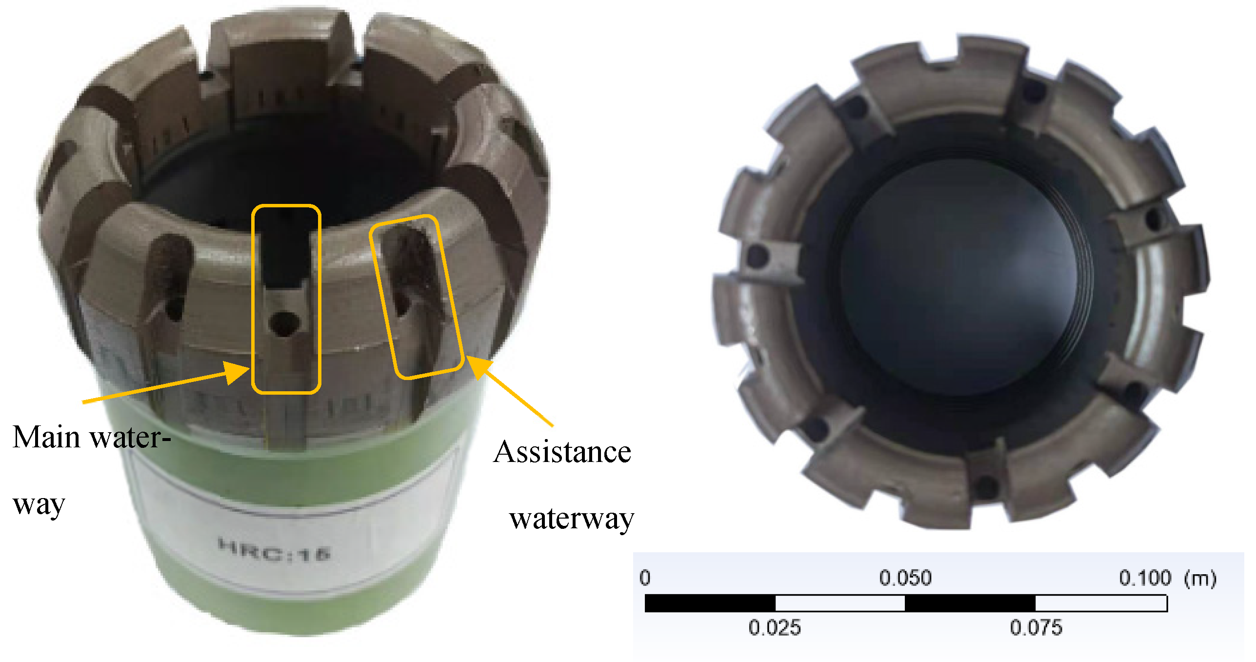
An impregnated diamond bit was fabricated according to the determined water system parameters as shown in
Figure 13. The matrix formula is a WC-based matrix formula system, which has good hardness and bending strength and is conducive to the service life of the bit [
30]. Sediments mainly dominate the strata within 200 m of the seafloor, so the coarse-grained and low-concentration diamond parameter scheme was selected. This scheme was expected to improve the rock fragmentation efficiency of the bit by increasing the exposed height of the single-grained diamond and the specific pressure of the bit crown. The hard, brittle SiC particles were added to the matrix to promote diamond exposure at a concentration of 15% and an average particle size of 425 μm [
13]. The cutting tooth structure is conical, which improves the bit crown pressure and drilling stability. The parameters of the diamond bit are listed in
Table 5.
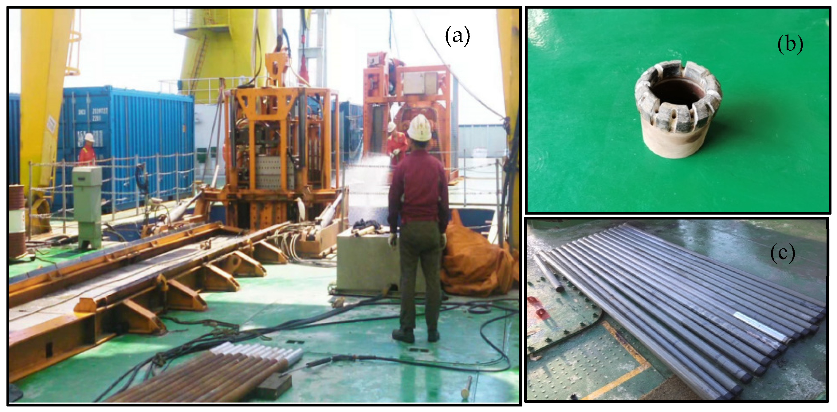
Field drilling tests were conducted in a mineral resource exploration project in a sea area of China. The seabed sediments in the target area are mainly composed of sediments and unconsolidated flow sand with hard, thin flint layers. A seafloor multi-purpose drilling rig with wire-line coring drilling technology was operated throughout the test. The height of the rig is 5.6 m and the bottom size is 2.2 × 2.2 m
2. The total weight of the seafloor drill is 8.3 tons in air and 6.7 tons in water. The maximum operating water depth is 3500 m. The seafloor drill can carry 25 core pipes simultaneously and has a maximum drilling depth of 62.5 m. Five stations drill over an operating water depth range of 900–1200 m, single hole drilling depth of 62.5 m, and drilling diameter of 97 mm. Seawater was used as drilling fluid with drilling pressure of 8–15 kN, rotation speed of 250–400 rpm, drilling fluid pump displacement of 50–80 L/min, and it ran to a depth of 2.5 m in each iteration. The test is shown in
Figure 14 and information regarding drilling operations is given in
Table 6.
The total cumulative drilling reached 312.5 m and average drilling efficiency reached 3 m/h. The average coring recovery rate was 86.6%. In the drilling process, the bit did not appear to be burnt due to a blockage of the water passage system. This suggests that the bit water passage system design is reasonable and can satisfy the real-world requirements for adaptive seafloor drill switching. To this effect, the proposed design may provide a workable reference for water passage systems and drill bit parameter schemes.


