Article

Resonance Control Based on Hydrodynamic Analysis for Underwater Direct Drive Wave Energy Converter

1
School of Electrical Engineering, Southeast University, Nanjing 210096, China
2
National Key Laboratory of Science and Technology on Vessel Integrated Power System, Naval University of Engineering, Wuhan 430033, China
*
Author to whom correspondence should be addressed.
J. Mar. Sci. Eng. 2021, 9(11), 1192; https://doi.org/10.3390/jmse9111192
Submission received: 25 September 2021 / Revised: 16 October 2021 / Accepted: 22 October 2021 / Published: 27 October 2021
(This article belongs to the Section Ocean Engineering)

Abstract

:
Wave energy has great prospect among many forms of marine renewable energy for its high density and storage. This paper proposes an underwater direct drive wave energy converter (UDDWEC), which is composed of a submerged point absorbing buoy and a linear-rotating axial flux permanent magnetic generator (LR-AFPMG). In addition, a maximum energy capture control strategy, resonance control, is derived for UDDWEC, based on small amplitude oscillation and hydrodynamic analysis. The proposed control strategy assumes the availability of sea condition such as wave height and period. This control strategy has three main characteristics. Firstly, this control strategy is derived based on hydrodynamic analysis of the submerged point absorber. Added mass, radiation damping and other hydrodynamic parameters are obtained to participate in UDDWEC dynamic model. Secondly, a LR-AFPMG is applied as power take-off device to realize energy conversion, which can improve the power density. Thirdly, small amplitude oscillation can be changed into long stroke rotary motion through the LR-AFPMG. The reliability and effectiveness of the proposed control strategy are assessed at various operation conditions for a heaving system and the validity for the UDDWEC is verified.

1. Introduction

Most of the earth is covered by oceans, which contains abundant marine renewable energy, such as wave energy, tidal energy and ocean thermal energy [1,2]. Compared with hydropower, wind energy, solar energy, geothermal energy and biomass energy, which are converted to electricity on a commercial scale all over the world, great progress should be made in the commercialization of wave energy [3,4]. Wave energy has merits of predictability and higher energy density compared with these successfully commercialized renewable energy. In addition, the distribution of wave energy is also in line with the regional characteristics of economic development, so wave energy has broad prospects for development [5,6].
From the perspective of structure of underwater direct drive wave energy converter (UDDWEC), many wave-to-wire models are summarized in [7], such as overtopping converters [8,9], oscillating water column converters [10,11] and wave-activated converters with different power take-off (PTO) systems, including hydraulic turbines [12,13,14], rotating generator with gearbox [15], linear generator [16,17] and so on. The mathematical models of PTO is shown in [18]. Linear generator has the characteristics of simple structure and high efficiency compared with other forms of PTO. The linear generator should adopt low-speed design for nature of wave, but thus leads to lower output voltage and power density [19]. So increasing the translator stroke of linear generator is the research direction at present, it mainly focuses on the application of magnetic gear technologies in PTO for the limited reciprocating stroke of wave [20]. When the buoy oscillates slightly underwater to keep the hydrodynamic parameters as constant as possible, the motion stroke and field traveling velocity can be expanded by the linear-rotating axial flux permanent magnet generator (LR-AFPMG) and then the power density can be increased. Moreover, protective measures for the device are also necessary, which can protect the device from damage in extreme sea conditions [21]. UDDWEC proposed in this paper provides a solution for the combining of underwater point absorbing buoy and LR-AFPMG. The underwater point absorbing buoy can reduce the wave excitation force, improve the reliability and concealment of the device. The LR-AFPMG can convert the reciprocating motion into the rotation of the rotor, which includes two non-contact accelerated processes: linear motion to rotating motion by magnetic lead screw (MLS) and the field accelerated process by axial flux permanent magnet generator (AFPMG) [22,23,24].Though MLS, already applied in wave energy conversion, non-contact between buoy and generator and spiral motion can be realized which reduces wear and frictional losses [22]. Then rotating motion can be convert to electricity by AFPMG.
From the perspective of control strategy of UDDWEC, the maximum power capture of wave power generation is one of the current research hotspots [25,26,27,28]. Power maximizing control strategies can be generally divided into phase control, amplitude control and resonance control [29]. By controlling the current of the generator, the resonance control makes the electromagnetic force of the generator and the wave consistent in amplitude and phase, so as to capture the maximum wave energy [3,27,30,31]. Classical and advanced control are all used in maximum wave energy capture. PI classical control is implemented in papers when wave force is acceptable [27]. Model predictive control (MPC) algorithms used in wave prediction burdened by heavy online computation which render them unsuitable for real-time application [16,30]. So many MPC-like algorithms attempted to diminish this burden [31,32]. Additionally, Reinforcement learning controller can also be applied and competitive in control perspective [33]. There are also many literatures in nonlinear hydrodynamic effects in fluid-structure interactions [34,35,36]. In this paper, the nonlinearity is ignored for computation complexity. A resonance control strategy based on the hydrodynamic analysis of buoy and an optimal oscillation range where the wave force changes slightly when the buoy moves in heaving are researched in this paper.
The paper is organized as follows. Section 2 contains the characteristics of the LR-AFPMG part and pulse width modulation (PWM) rectifier circuit. In Section 3, the force analysis of UDDWEC for motion is conducted in detail. Through the force analysis based on hydrodynamics, the wave excitation force and radiation force of the buoy are introduced into the force equation of the system. Then in Section 4, the q-axis current equation of resonance control strategy and the active and reactive power components are derived in detail. In Section 5, the hydrodynamics software is used to obtain and optimize the buoy parameters and find the ones with small amplitude oscillation range of wave force. Then the change of hydrodynamic parameters of buoy in small amplitude oscillation is considered and compared with the constant condition where the change of wave force caused by the up and down movement of the buoy can be ignored. Then MATLAB is used to analyze the validity and effectiveness of the proposed resonance control and UDDWEC system. Finally, conclusion is drawn in Section 6.

2. System Modeling

Conventional direct drive wave energy converter (DDWEC) device using permanent magnet linear generator (PMLG) eliminates the inefficient transmission device such as gearbox and achieves simpler mechanical structure. However, due to the direct connection between buoy and translator, the wave exciting force is directly transmitted to the linear generator translator through the shaft. Therefor the low-speed linear reciprocating wave motion will be directly transmitted to the translator and an adaptation to a low-speed design is needed, which leads to a lower output voltage and power density. Not only that, since the buoy and translator are directly connected, the generator may be irreversibly damaged under extreme sea conditions for the reason that the wave exciting force is the largest on the wave surface when the device has no survival mode. To solve the above issues, a new device, namely UDDWEC, is proposed in this paper. The overall configuration of the UDDWEC system is shown in Figure 1a.
The underwater buoy can effectively reduce wave force to protect device in extreme conditions for the wave force decreases sharply with the increase of the distance from the surface. By applying LR-AFPMG, shown in Figure 1b, in UDDWEC, the output voltage and power density can be improved. LR-AFPMG employs MLS and AFPMG together, it combines the merits of them and realizes the soft connection between the buoy and generator rotor. The screw and nut of MLS are directly connected to the buoy and AFPMG rotor, respectively. When the wave comes, the submerged buoy moves up and down and transmits the motion to the screw of MLS through the shaft. Then the nut rotates under the action of magnetic field and the linear motion of the buoy is converted to the rotary motion. By employing MLS, the spiral motion track is realized, and the stroke and velocity are increased. The rotor in the AFPMG, installed on the nut of MLS, is composed of modulation teeth made of permeability material and can switch the magnetic circuit in armature windings. Based on the principle of electromagnetic induction, an induced voltage is generated on the armature winding. The magnetic field speed through the air gap will be accelerated, according to the principle of magnetic field modulation. When low-speed reciprocating wave motion comes, the motion can be accelerated by MLS and magnetic field modulation simultaneously and finally the speed of the rotor will reach approximately 1200 rpm, which can further improve the output voltage and power density consequently.
The submerged buoy uses the pressure difference generated between the wave crests and troughs over the upper and lower surfaces to perform six degrees of freedom movement, including surge, sway, heave, roll, pitch and yaw. In this paper, only the heaving motion of buoy is considered when other degrees of freedom and effects are ignored. When in the equilibrium condition, the total gravity of buoy and LR-AFPMG are overcome by pressure difference over the upper and lower surfaces of buoy. If the trough is over the system, the water pressure will be reduced and the buoy rises. Then, LR-AFPMG will be driven by the buoy and convert kinetic energy from wave into electrical energy. This form of UDDWEC differs from other devices working in pressure differential such as Archimedes Wave Swing (AWS) and underwater wave energy converter (UWEC) in three points [27,37]:
  • When the buoy is running in heaving, the pressure difference between the upper and lower surfaces can be regarded as fixed because the distance between them is fixed. However, the AWS consists of a hollow cylinder and lib and the cylinder is filled with air and sealed by the lib. The lib is moving and cylinder is fixed, which causes the pressure difference between the upper and lower surfaces to change, when the wave comes.
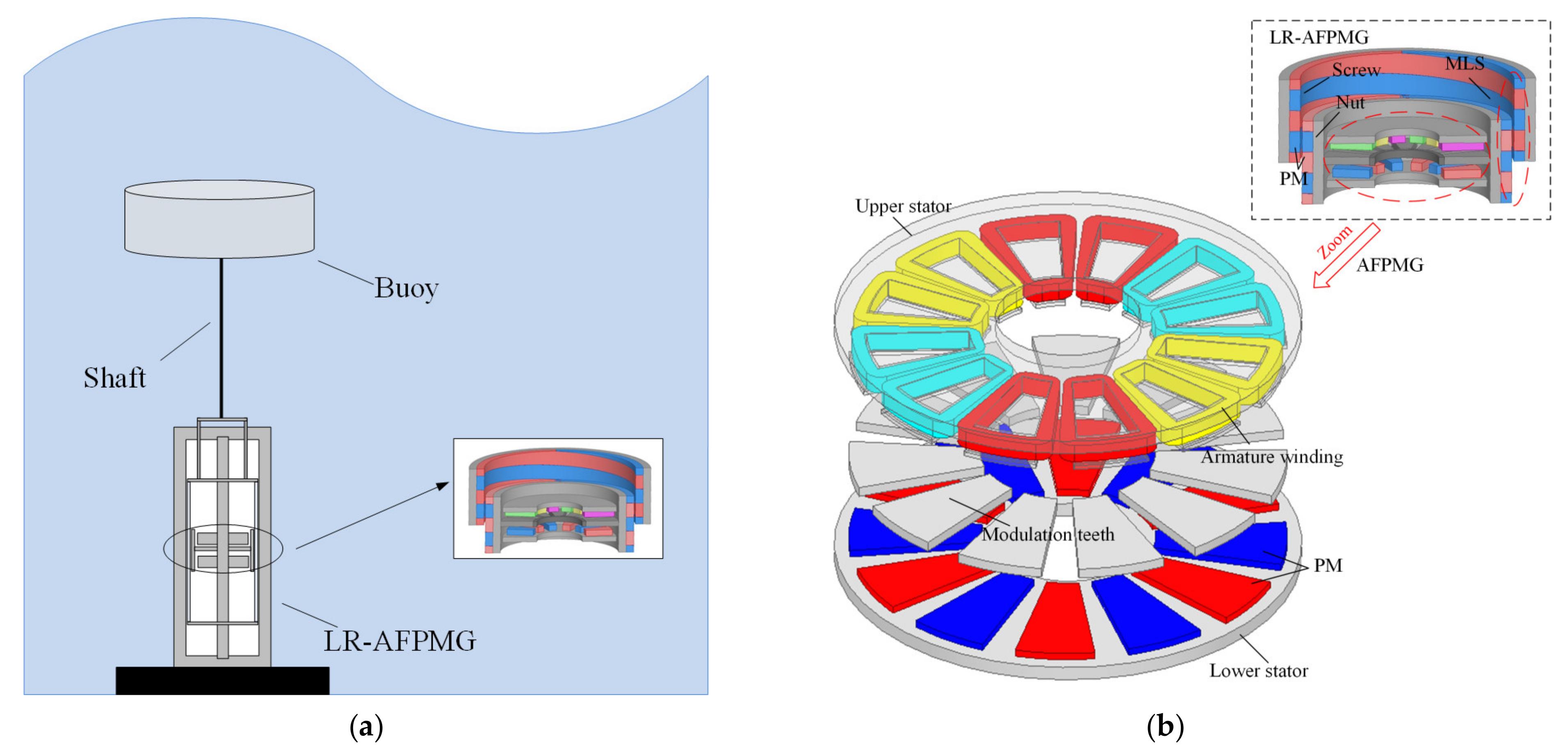
  • In contrast with the AWS generator installed inside the cylinder, the generator proposed in this paper is installed under the buoy, and connected to the buoy by a shaft. Using this topology, the workload can be reduced when installing or maintaining the device. By using the LR-AFPMG composed of MLS and AFPMG, the generator and buoy are not directly connected, but a soft connection is realized through the MLS, which can further protect the power generation device from extreme ocean conditions and improve the reliability of the system.
  • UWEC drives a pump fixed on the seabed through a cable to convert wave energy into hydraulic energy and send it to the shore for energy conversion. However, the proposed system directly realizes energy conversion by replacing the pump with LR-AFPMG. In this way, the power generation efficiency can be increased and the process loss can be reduced.
For the generator side of the power generation system, the PWM rectifier circuit is used to control the current and electromagnetic force to make the system in resonance state. In this condition, maximum wave energy can be captured. The angle of rotor and current signals of the generator side are collected to output the IGBT on-off control signal through the resonance control strategy. The principle of generator side control and controllable circuit is shown in the Figure 2.

3. Force Analysis for Motion

Most wave energy conversion models in literatures assume that the excitation force on the buoy is sinusoidal and no hydrodynamic analysis based on the characteristics of the buoy conducted in simulation [27]. In this paper, based on the linear potential theory and the dynamic equation of the generator, the frequency domain motion equation of UDDWEC is established. Before deriving the frequency domain equation, several basic assumptions are introduced.
  • It is assumed that the fluid is an ideal incompressible fluid without rotation, and the motion amplitude of the buoy is small, so the linear potential theory can be used to analyze this problem.
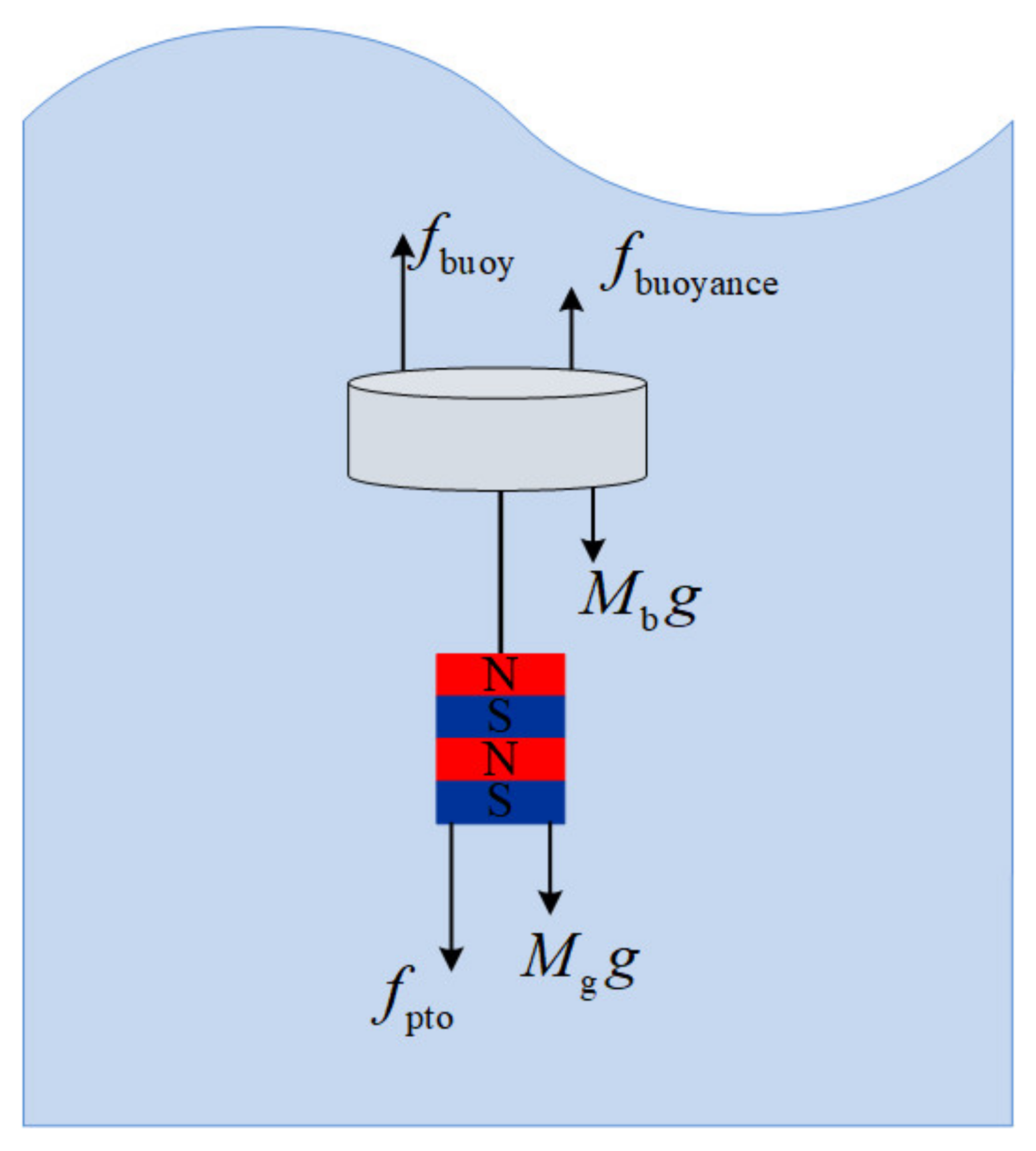
  • Only the heaving motion of the buoy is considered in the force analysis. Generally, the oscillating buoy has six degrees of freedom motion, but considering that the generator is mainly driven by the heaving motion of the oscillating buoy.
  • The shaft is installed between the buoy and generator, so the motion of them is synchronous.
  • The viscous force and mooring force acting on the buoy have little effect on UDDWEC and thus can be ignored.
  • Since the buoy of UDDWEC is under the sea surface, the device should be in an initial balanced state without external disturbance, so the buoyance force experienced by the oscillating buoy can just offset the total mass of the buoy and generator.
Based on the above basic assumptions, the analysis of force can be conducted and shown in Figure 3. The frequency domain motion equation of UDDWC can be established. According to Newton’s second law, the motion equation of the whole system can be expressed as:
M ¯ z ¨ = f buoy ( t ) f pto ( t )
where M ¯ ( = M b + M t ) , M b and M t are total mass, the mass of buoy and the equivalent linear generator’s translator of LR-AFPMG, respectively; z ¨ is synchronous acceleration of buoy and translator; f buoy ( t ) is the hydrodynamic force acting on the buoy; f pto ( t ) is the electromagnetic force on the translator of the equivalent linear generator.
Carrying out Fourier transform to Equation (1), the motion equation of the system in the frequency domain can be obtained as follow:
ω 2 M ¯ Z ( j ω ) = F buoy ( j ω ) F pto ( j ω )
where Z ( j ω ) is motion displacement. The hydrodynamic force acting on the buoy can be divided into three parts according to the potential theory [38]:
F buoy ( j ω ) = F e F r
where F e is the wave excitation force and F r is the radiation force. They can be further expressed as:
F e = i ω ρ s ( ϕ I + ϕ D ) n d S F r = i ω ρ s ϕ R n d S
where ρ is the density of water; S is the wet surface area of buoy; n is the unit vertical normal of buoy; ϕ I , ϕ D and ϕ R are incident wave velocity potential, diffraction potential and radiation potential, respectively. The diffraction potential and radiation potential can be obtained according to the boundary conditions. The sum of Froude-Krylov (FK) force and diffraction force obtained from the incident and diffraction potential is called the wave excitation force F e .
In the frequency domain, the wave excitation force F e has the following relationship with the incident wave amplitude η :
F e ( j ω ) = f e ( j ω ) η
where f e ( j ω ) is the wave excitation force at unit wave amplitude; Similarly, the radiation force F r can also be expressed as:
F r ( j ω ) = j ω R m Z ( j ω ) ω 2 M a Z ( j ω )
where R m is radiation damping and M a is added mass.
Similarly, in the frequency domain, the electromagnetic force F pto can be written as:
F pto ( j ω ) = ω 2 M pto Z ( j ω ) + j ω R pto Z ( j ω ) + K pto Z ( j ω )
where M pto , R pto and K pto are mass term, damping term and stiffness term, respectively, which are proportional to acceleration, velocity and displacement, respectively, in electromagnetic force equation.
According to above force analysis and the convention of the duality principle that the force is equivalent to the voltage drop, as all the force terms can be written in form of Ohm’s law. Meanwhile, the damping term, mass term and stiffness term are equivalent to resistance, inductance and capacitance in circuit, respectively. The equivalent circuit diagram of the whole system is shown in Figure 4, where M is the total mass of moving parts including added mass, mass of buoy and other.

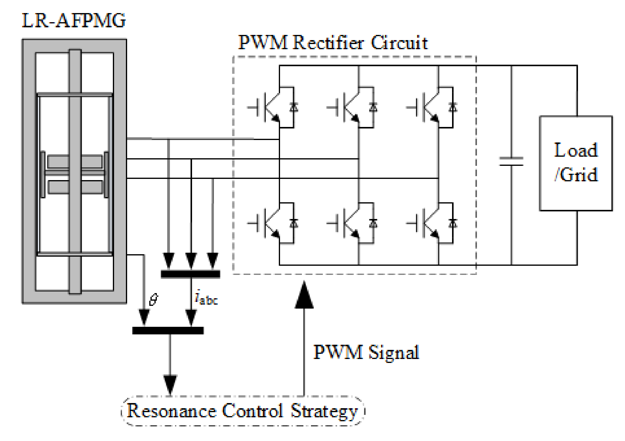
4. Control Strategy of Generator

The generator side converter adopting PWM rectifier circuit, which can adjust the duty ratio and change the current to the desired amplitude and phase, aims to extract as much energy as possible from incident wave. To achieve this objective, the PTO need to be regulated in resonance with the wave, which can be performed by changing the electromagnetic force F pto to match the radiation force F r . In other words, F pto should be the conjugate relationship of F r . Then the velocity of the device and F pto are in phase consequently. Under this circumstance, the generator can absorb the maximum energy from the wave and convert it into electrical output.
Cosequently, the following condition must be satisfied:
R m + j ω M = R pto j ω M pto + j 1 ω K pto
where ω is the angular frequency of wave and M ( = M ¯ + M a ) is the sum of total mass and added mass. Condition (8) denotes that the resonance at different wave periods, the mass term, damping term and stiffness term should be regulated by changing the current in generator. The mathematical model of LR-AFPMG mentioned in direct-quadrature ( d q ) reference frame fixed to the rotor by applying Park’s transformation is [39]:
u ds = R s i ds + ω e L q i qs L d p i ds u qs = R s i qs ω e L d i ds + ω ψ f L q p i qs T pto = 3 2 N i qs [ L q L d i ds + ψ f ]
where p is the differential operator; ω e is the electric angular frequency in generator; u ds , u qs , i ds , i qs , L d , L q are voltage, current and inductance of direct and quadrature axes, respectively; ψ f and R s are the permanent flux linkage and phase resistance, respectively; T pto is the torque of generator and N is the number of pole pair.
By converting the linear motion of buoy to rotating motion of rotator in AFPMG. The angular velocity of rotor can be expressed as [24]:
ω rotor = G LR v buoy
where v buoy is the velocity of the buoy and G LR is the gear ratio. Meanwhile, electromagnetic torque is:
T pto = F shaft / G LR
where F shaft is the tension on the shaft. Then in model establishment, the motion and electromagnetic force in equivalent linear generator can be expressed:
F pto = ω rotor T pto / v v = ω rotor τ LR / π
where τ LR is pole pitch of MLS; F pto is the electromagnetic force equivalent linear generator translator; v is velocity of equivalent linear generator translator which is also equal to v buoy for synchronous motion. Before the control model is established, the hydrodynamic parameters of the buoy are obtained according to the hydrodynamic simulation. The conversion of frequency domain model to time domain model is as follows:
F e = f e η sin ( ω t + φ )
where ω and φ are circular frequency and phase shift of wave exciting force.
When the generator can capture the maximum wave energy, the velocity and electromagnetic force should meet the requirements:
v = F e 2 R m = f e η 2 R m sin ( ω t + φ )
F pto _ ref = f e η 2 1 + ( ω M R m ) 2 sin ( ω t φ arctan ω M R m )
The stator current is used to generate torque and the cancel the reluctance torque. The control strategy of direct axis current i d = 0 is adopted, the reference currents of the direct and quadrature axis are as follows:
i ds _ ref = 0 i qs _ ref = f e η τ 3 π N ψ f 1 + ( ω M R m ) 2 sin ( ω t φ arctan ω M R m )
There are damping and reactance terms in the electromagnetic force of the generator, they generate active power and reactive power, respectively, so the active power and reactive power collected by the generator from the waves are as follows:
P = ( f e η ) 2 4 R m 1 + ( ω M R m ) 2 cos ( 2 φ arctan ω M R m ) Q = ( f e η ) 2 4 R m 1 + ( ω M R m ) 2 sin ( 2 φ arctan ω M R m )
It can be seen from Equation (9) that coupling terms exist between the reference frame. When the generator parameters are known, feedforward compensation method can be used to eliminate the coupling and realize accurate linearization control, as shown in Figure 5.

5. Simulation Analysis of UDDWEC

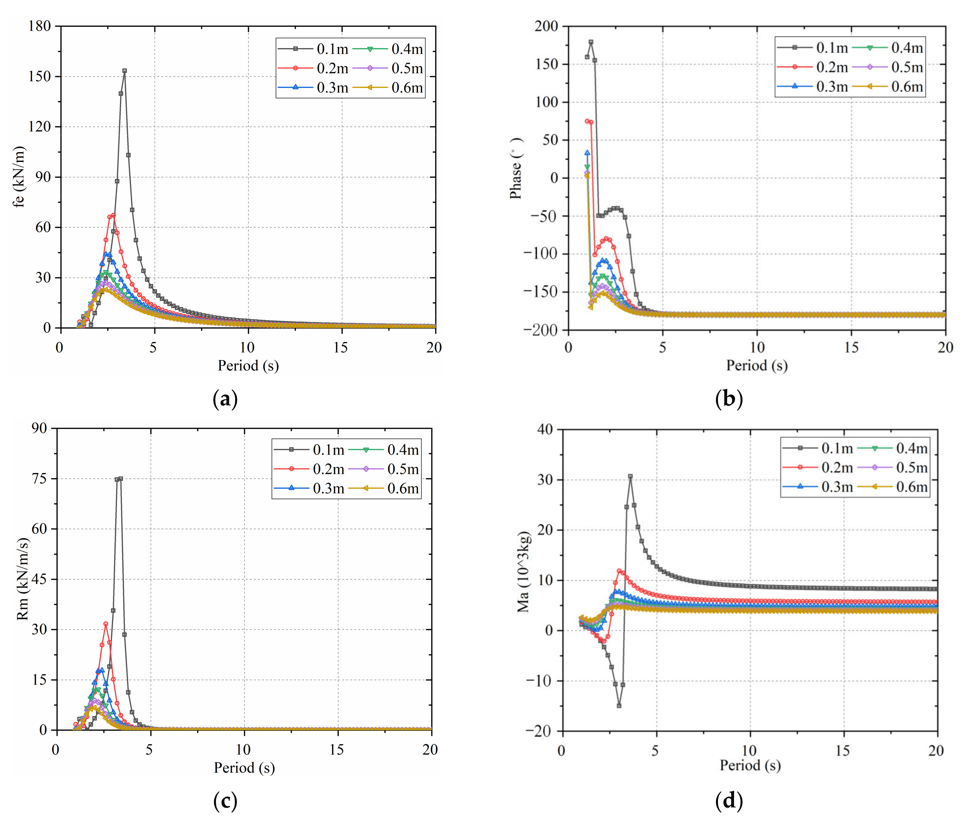
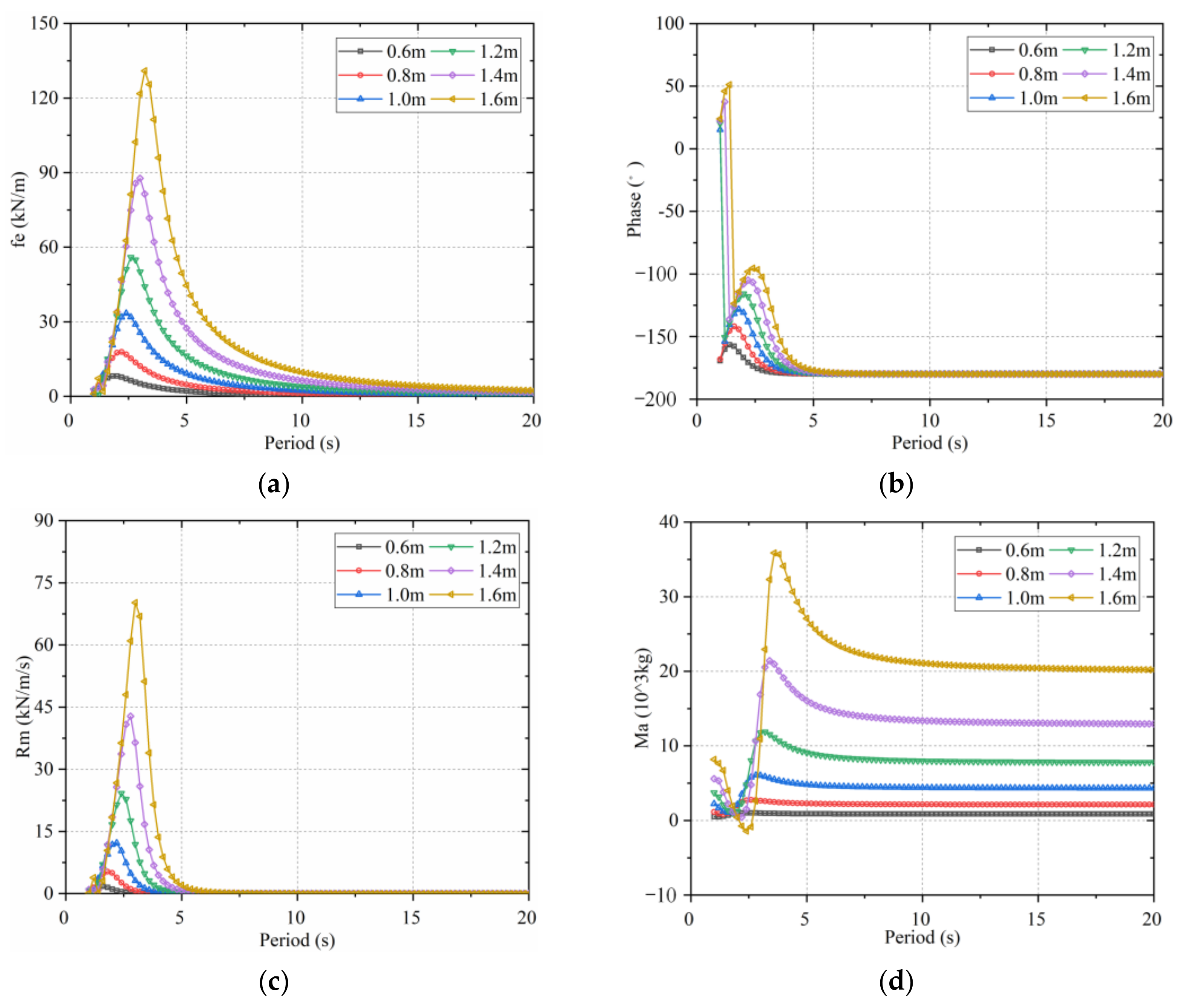
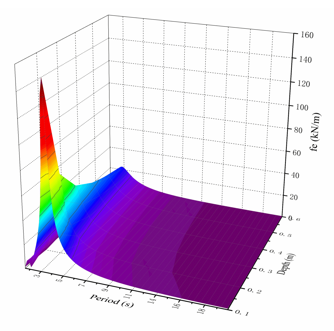
5.1. Hydrodynamic Analysis of the Buoy

In Section 3, the buoy of UDDWEC can be expressed by voltage source and impedance in the equivalent circuit, respectively, according to the principle of duality. In this section, a panel-based software based on linear potential theory is used to analyze the wave excitation force, radiation force and so on. Mesh parameter defeaturing tolerance and maximum element size are 0.02 m and 0.06 m, respectively.
For a cylindrical buoy with radius 1 m and height 0.5 m, the unit wave amplitude wave excitation force, the phase shift of wave excitation force, radiation damping and added mass at different submerged depths are analyzed (changing the distance between the top of buoy and sea level), as shown in Figure 6.
It can be seen from Figure 6 that as the depth of the buoy increases, the hydrodynamic parameters decrease consequently, especially in the range of 0.1 to 0.2 m. For the wave exciting force, radiation damping and added mass, when the depth is greater than 0.3 m, the change amplitude is small, while the phase shift of wave exciting force is always equal to −180° when the wave period is greater than 3.4 s. Therefore, in order to keep the amplitude of wave exciting force close to constant when the buoy moves up and down as much as possible, the depth of buoy submerged should be greater than 0.3 m. The application scenario of the UDDWEC in this paper is the Yellow Sea of China, whose wave period mainly ranges from 4 s to 5 s. When the submerged buoy proposed in this paper is used, it can effectively avoid the irreversible damage of the power generation device caused by the extreme wave force under the extreme sea conditions for the wave force will decrease sharply with the increase of depth.
The added mass force is generally proportional to the acceleration of the buoy, but in the opposite direction. In other words, when the buoy is forced to oscillate, the surrounding fluid tends to hinder the acceleration of the buoy. In this case, the added mass is positive. However, in case of high-frequency oscillation, due to the fast motion frequency of the object, the surrounding fluid has reaction time, the fluid phase may no longer hinder this acceleration trend. At this time, free-surface effects are shown to be important, the acceleration of the object may be promoted and the added mass is negative. There is another trend. When the buoy is far from the sea surface, the added mass is positive, which corresponds to the forced oscillation of a finite volume object in an infinite field, and the fluid will always hinder the acceleration trend.
The depth of the device should also be determined according to the capacity of the wave power generation device. In addition, according to Equation (17), the output active power and reactive power of the power generation device are all related to the added mass and radiation damping of buoy when the device is working. With the increase of the added mass, the proportion of reactive power output by the power generation device will be larger, while the proportion of active power output will be smaller. Meanwhile, the power will flow bidirectional between the power generation device and the back-end part, and the direct current (DC) bus voltage will fluctuate greatly. The rated capacity of generator and power devices will also increase correspondingly under this circumstance. Therefore, the relationship between added mass and radiation damping should be fully considered.
When the power generation device is working, the buoy moves in heaving under the combined action of wave exciting force, electromagnetic force and so on. It can be known from the previous analysis that when the buoy is at different submerged depths, the parameters change greatly. Therefore, it is necessary to consider the depth sensitivity, oscillation range and hydrodynamic parameters to reduce the variation of wave force amplitude.
There is little effect on the hydrodynamic parameters in the heaving direction when the height of the cylinder is changed. The reason is that the wave on the horizontal section of cylinder does not change. The height (0.5 m) and depth (0.4 m) of the cylinder remains unchanged, and the radius of the cylinder is changed from 0.6 to 1.6 m to analyze its influence on the hydrodynamic parameters. The results are shown in Figure 7.
According to the result of hydrodynamic analysis, it is obvious that the larger the radius of the cylinder, the larger the hydrodynamic parameters. When the radius of the cylinder increases by 0.2 m each time, the peak values of the parameters are nearly doubled.
Although increasing the radius of the buoy can capture more wave energy and make the peak period point adapt to the average sea condition, the rapidly increasing wave excitation force does not match the UDDWEC, so it can only be suitable for the traditional rotary power generation device. Meanwhile, it should be noted that when the wave period is about 5 s, the ratio of added mass to radiation damping will be large. As a result, the output reactive power component fluctuates greatly and the output active power component is relatively small in this case. In order to increase the active component and decrease the reactive component, we can increase the damping or spring in the system to improve the performance.
In this case, the total radiation force in the system can be expressed in two parts, as shown in the following equation:
F r _ all = F r + F r _ add
where F r is the radiation force analyzed in Section 4 and F r _ add is additional damping force added to the system to increase the active power component which can be expressed as:
F r _ add ( j ω ) = R m _ add Z ˙ b
There is a little effect on the change of wave exciting force when the radius of the buoy is changed at the wave period (4–5 s). However, when the buoy is at different submerged depths, the exciting force changes greatly, as shown in Figure 8. In order to reduce the influence of the wave exciting force caused by the up and down motion of the buoy, the design of the buoy in this paper is 0.4 m underwater.
When the cylindrical buoy has a radius of 1 m, a height of 0.5 m, an underwater depth of 0.4 m, the effectiveness caused by the change of hydrodynamic parameters with depth is verified. Taking the Yellow Sea as the simulation parameter whose wave period is concentrated in 4 s to 5 s. When the wave period is 5 s and the wave amplitude is 0.4 m, conditions that hydrodynamic parameters change with depth and keep constant are compared, the results of response are shown in Figure 9. In Figure 9a, two curves represent the hydrodynamic parameters change with the oscillation of the buoy by data fitting and hydrodynamic parameters keep constant, take the equilibrium position value as the fixed, respectively. The strokes of the translator in these conditions are from −0.108 to 0.057 m and from −0.116 to 0.06 m, respectively. Moreover, according to the results in Figure 9b, when the translator moves, the difference of wave excitation force is only 143 N. The reason for the above effect is that the wave amplitude is 0.4 m and the buoy motion is small oscillation, oscillation range is only about 0.13 m. The error of stroke and force between them are about 4.8% and 1.6%, so it is feasible and reliable to ignore the change of hydrodynamic parameters and keep them constant in buoy oscillation range. Compared with the traditional DDWEC, the linear generator is adopted, that is, at the position of the MLS, the nut is the translator of the linear generator. The pole pitch of MLS corresponds to that of linear generator translator. However, the UDDWEC proposed in this paper adopted LR-AFPMG, one pole pitch of the MLS corresponds to one turn of the AFPMG rotor. By reasonably configuring the pole pitch of the MLS and increasing the screw stroke, the rotation times of the AFPMG rotor in a wave cycle can be increased, that is, the velocity and power density of the generator can be increased.

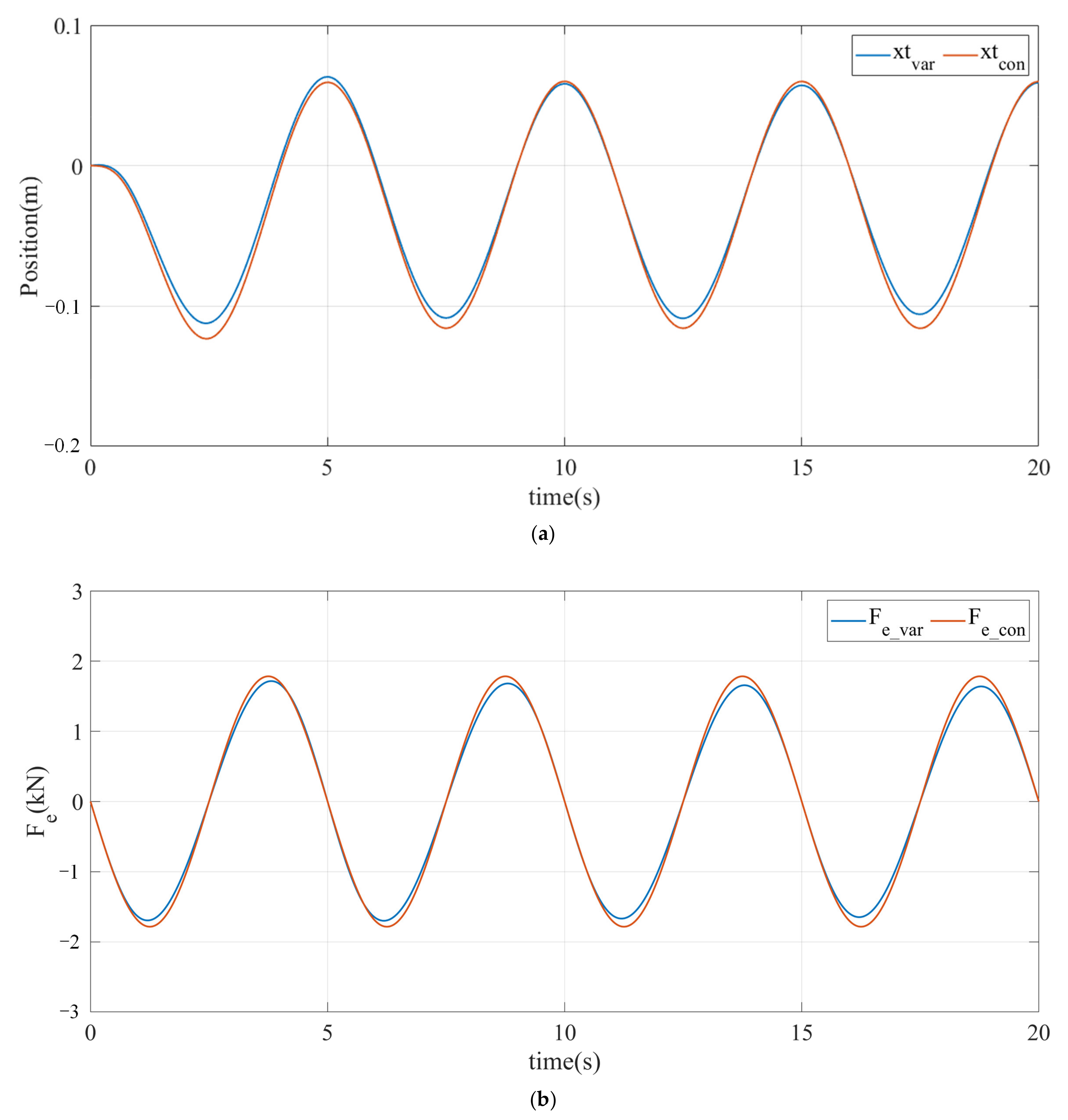
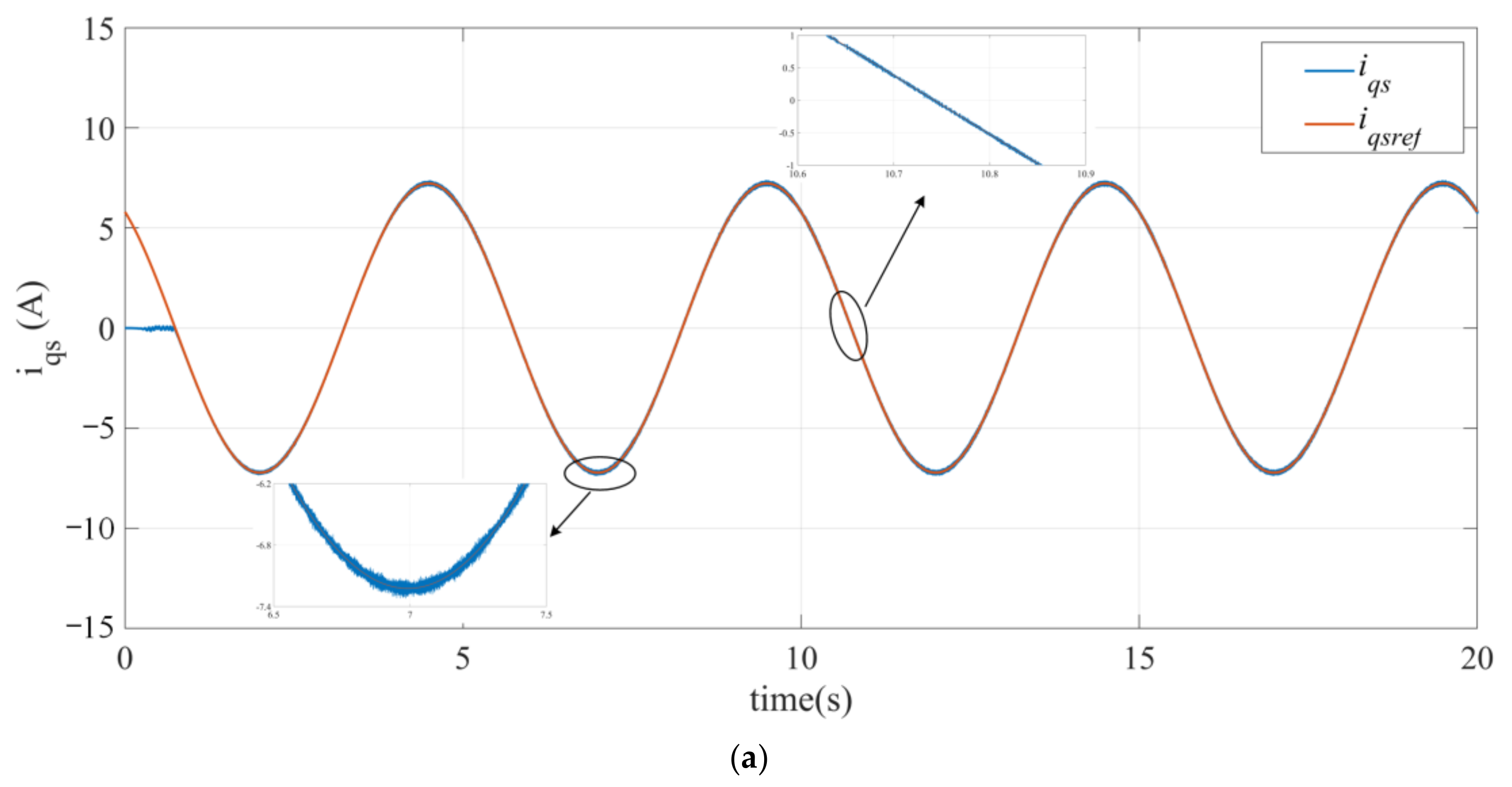
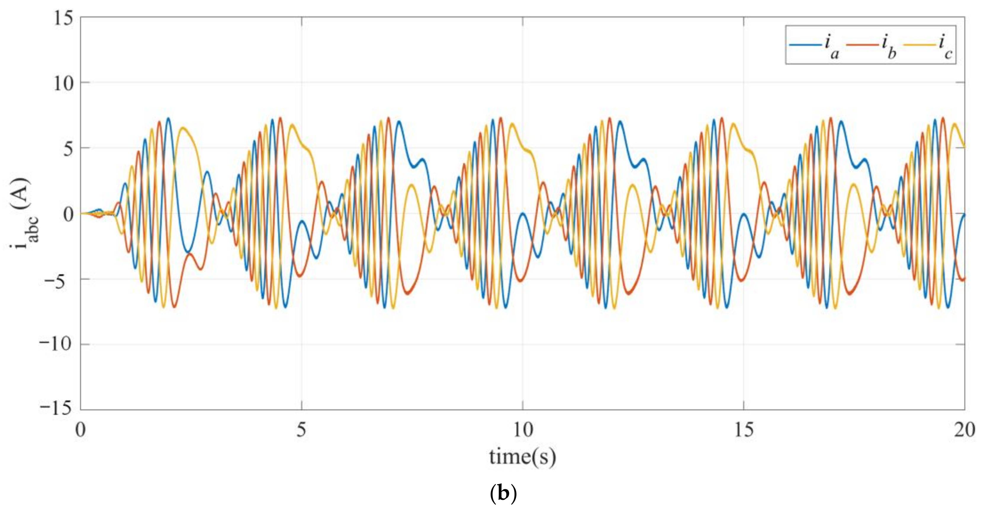
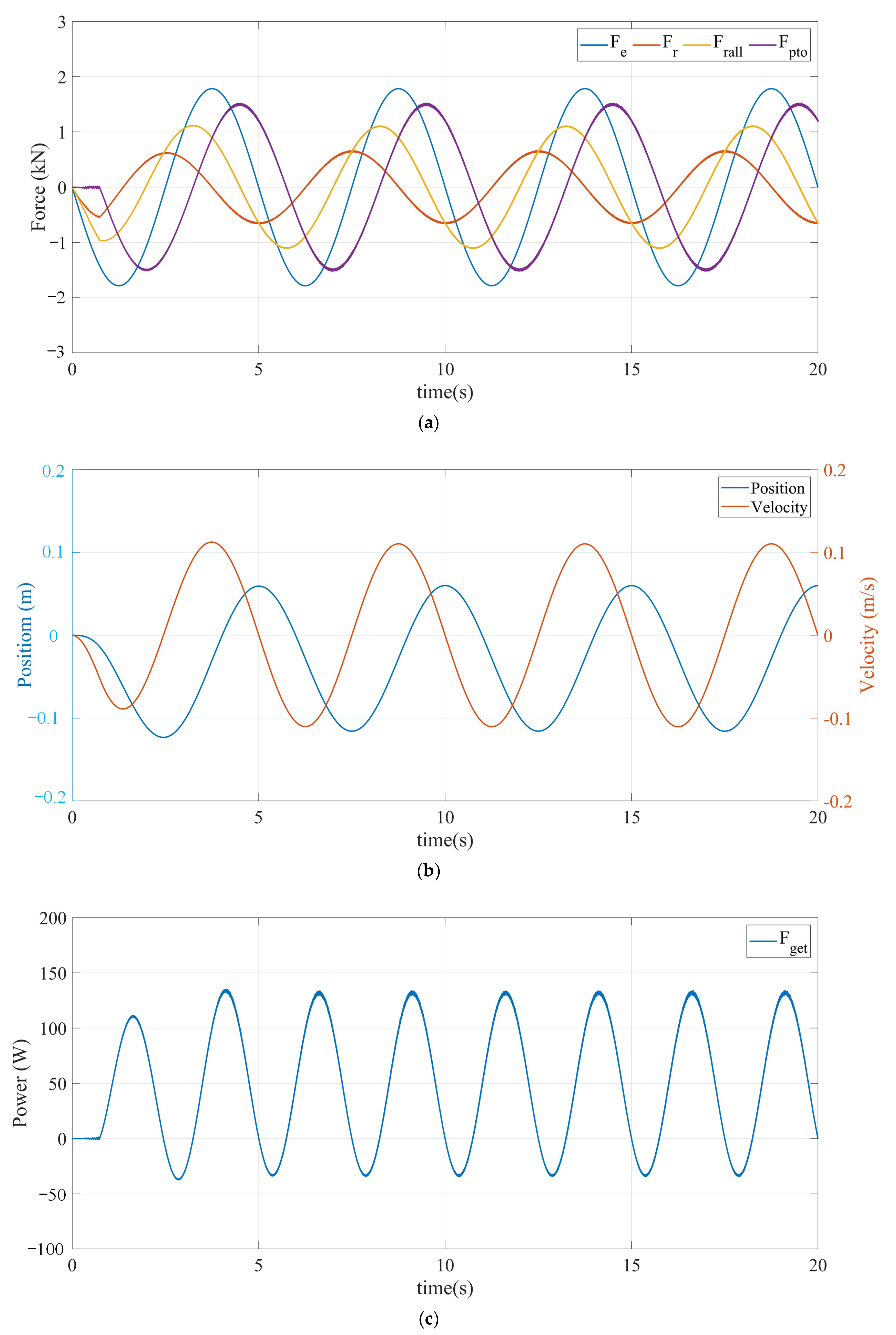
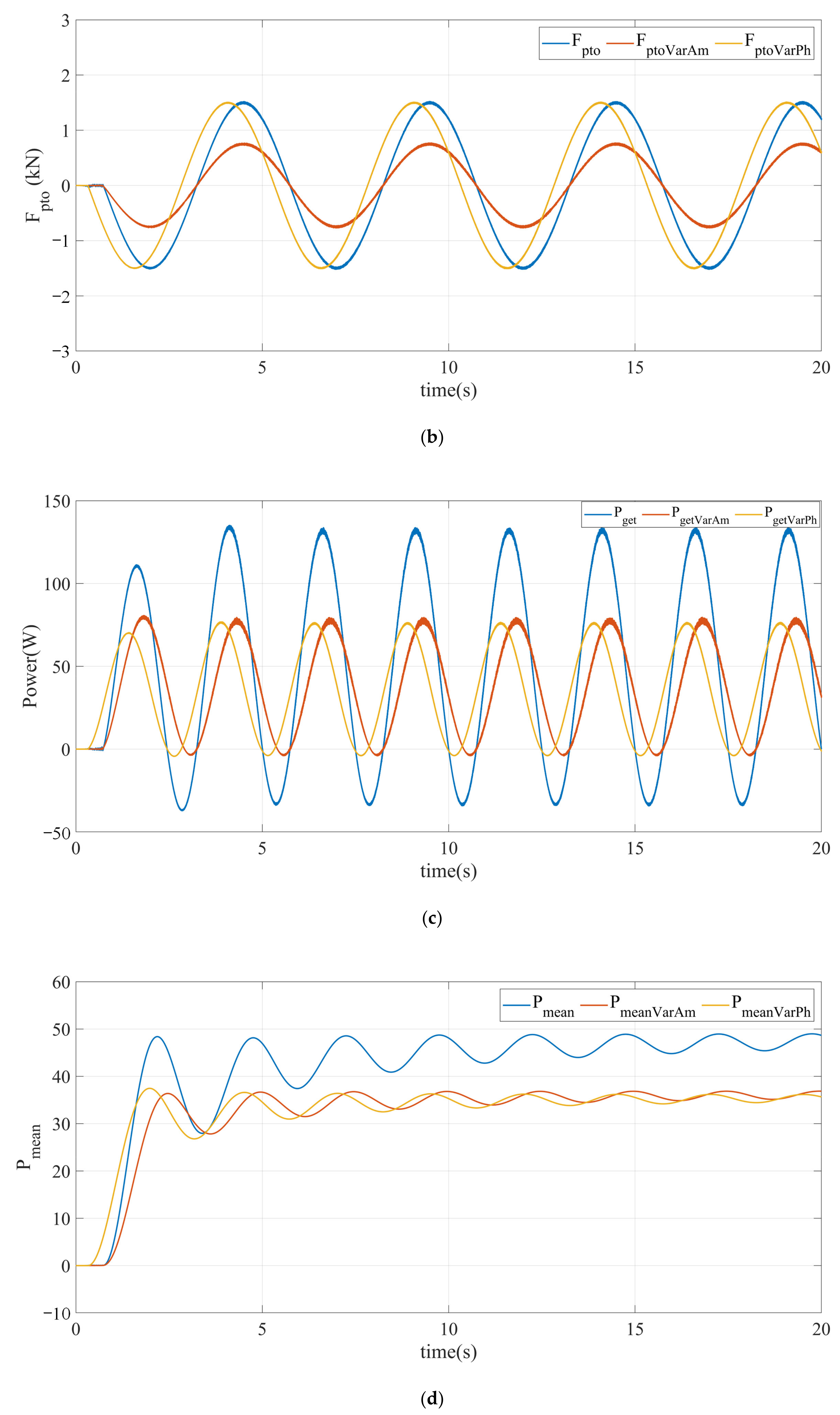
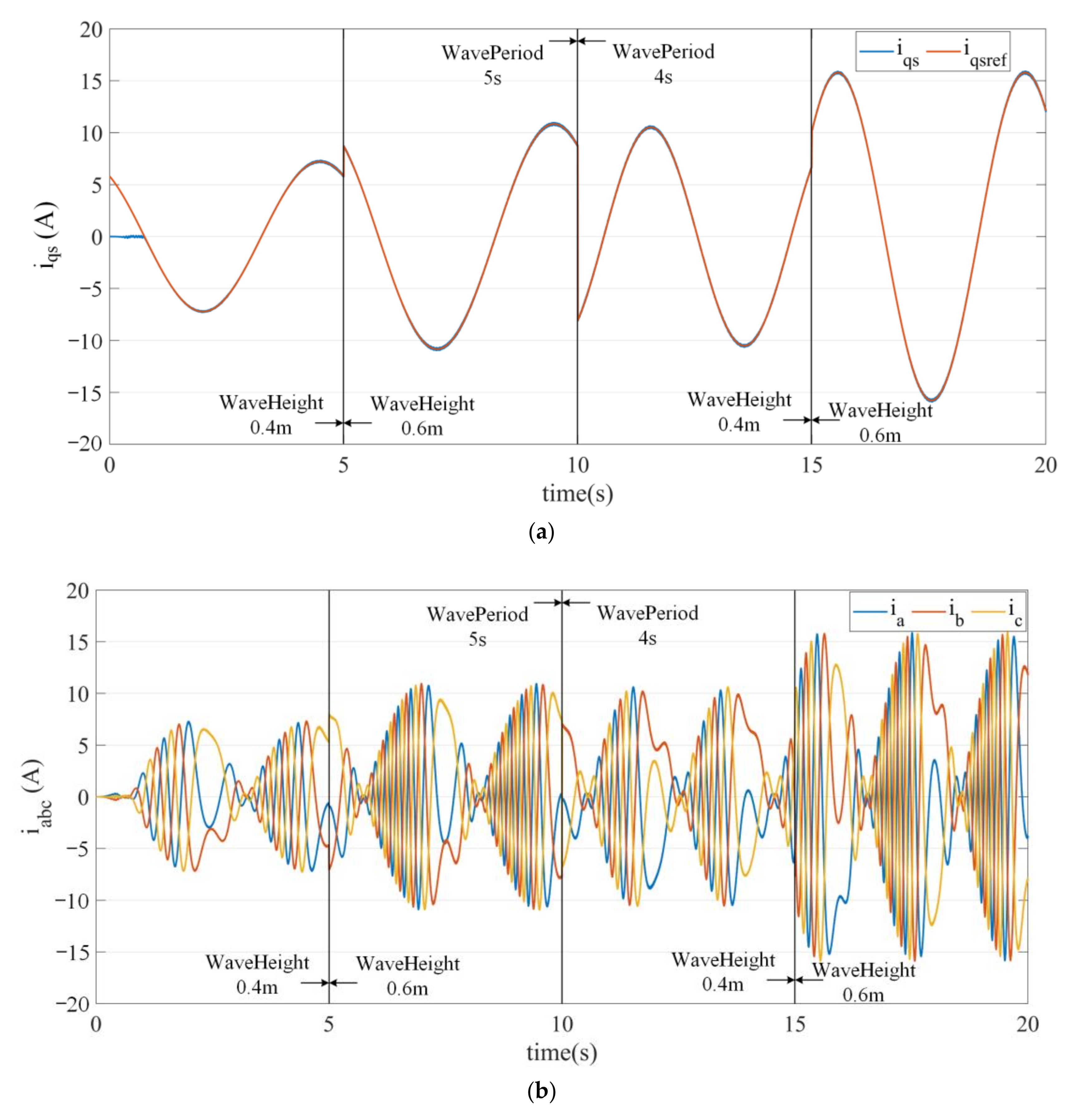
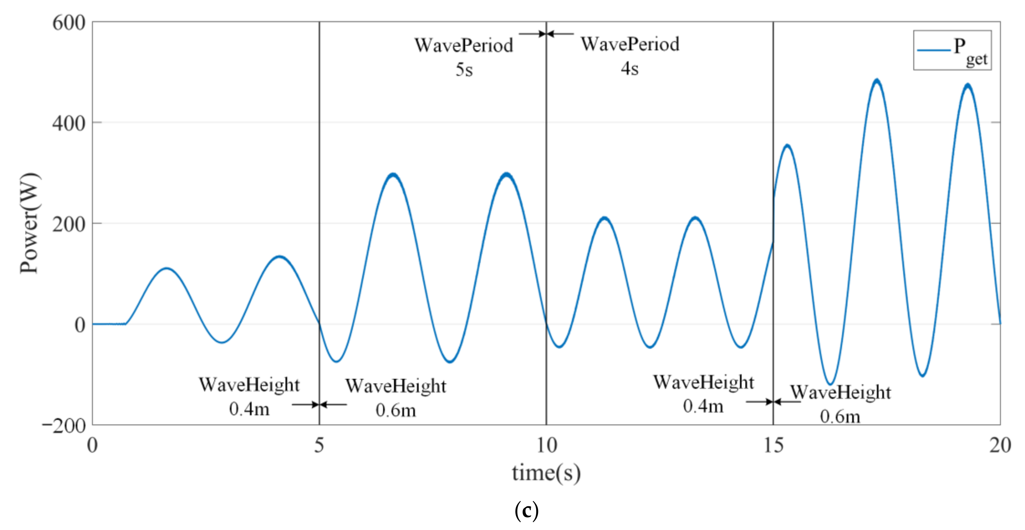
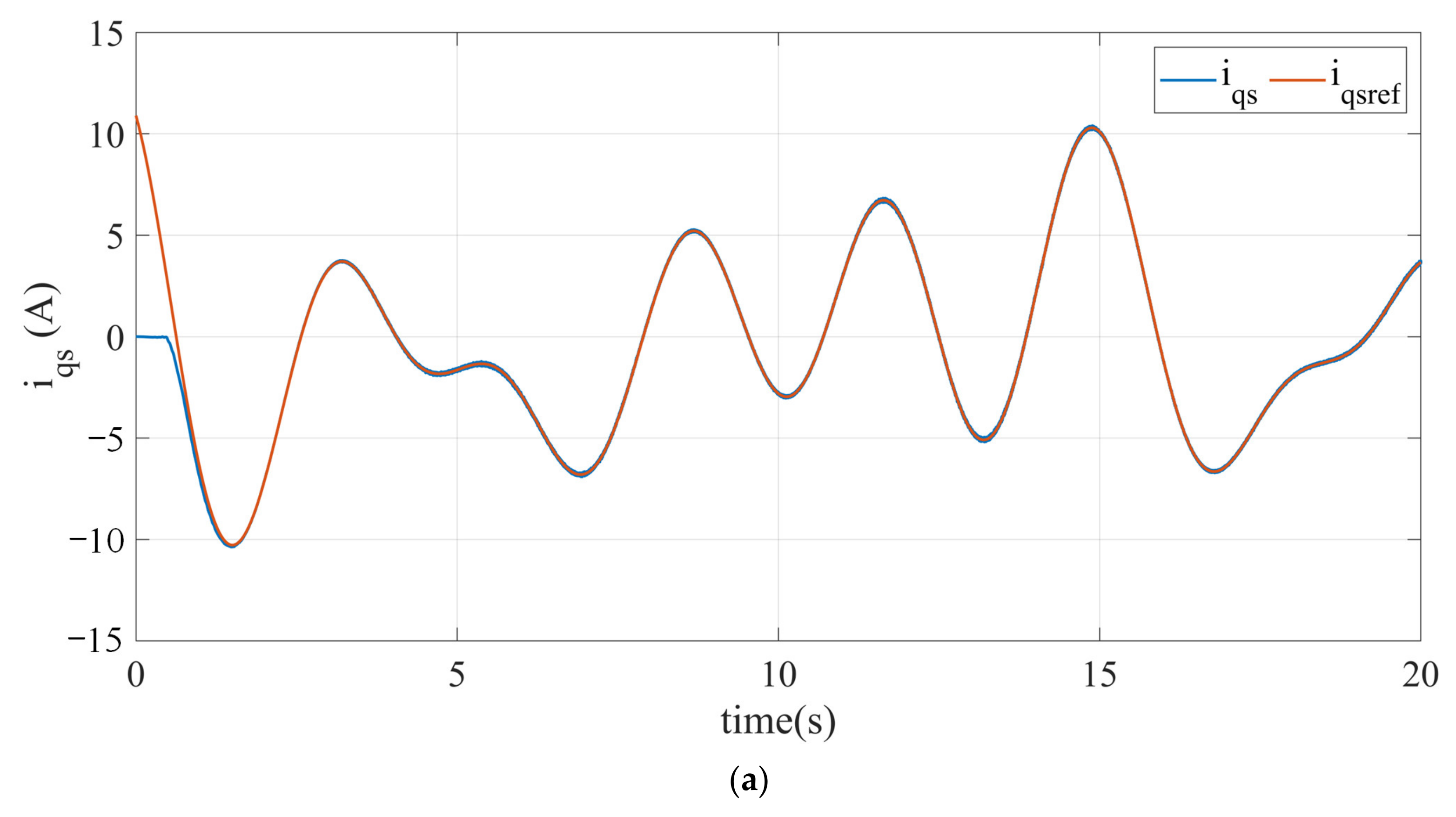
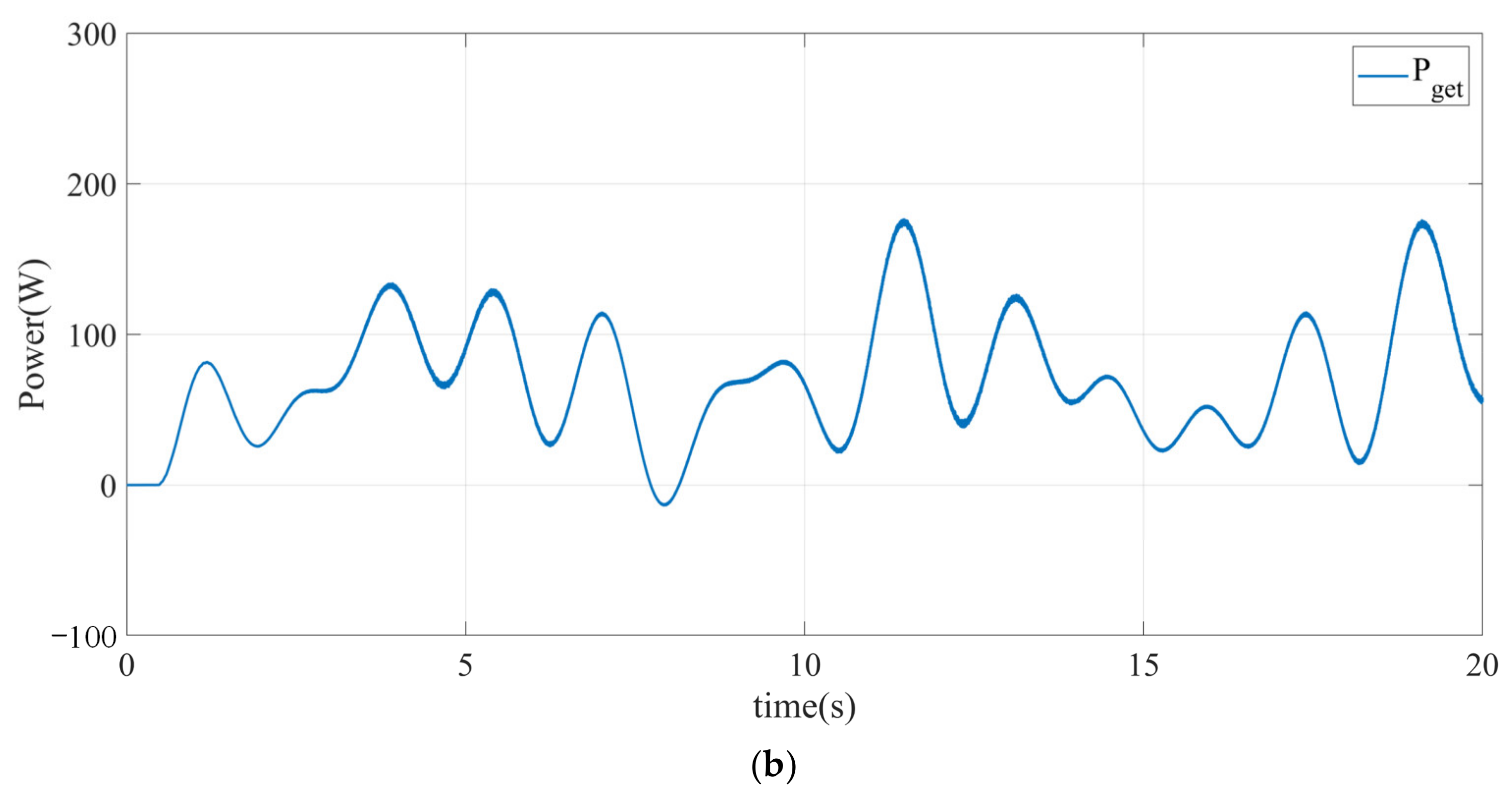
5.2. Resonance Control Simulation of UDDWEC

According to the previous hydrodynamic analysis of the buoy, analysis of the working condition of the whole system will be introduced in this section. Changes of hydrodynamic parameters are ignored when the buoy moves in heave and the parameters at equilibrium position are regarded as constant values in all time. Meanwhile, LR-AFPMG proposed in the Section 2 is equivalent to a linear generator to simplify the establishment of the system. The detailed system data of UDDWEC are given in the Table 1.
The UDDWEC system based on hydrodynamic analysis was established in MATLAB. Hydrodynamic parameters calculated from panel-based software worked as known inputs and the generator adopted the controlled voltage source model. The simulation model is established according to the control block diagram in Figure 5, in which the dq axis reference currents are obtained according to Equation (16). The simulation time step is 5 × 10⁻⁶ in discrete model. Several sets of case studies are presented under different sea conditions in this section. The wave exciting force per unit wave amplitude is 8917.85 N, the radiation damping is 77.97 N(m/s) and the added mass is 4671.47 kg, according to the hydrodynamic analysis. Meanwhile, an added radiation damping 8 × 10³ N(m/s) is added to increase the active component. The electrical and mechanical dynamic responses of UDDWEC are shown in Figure 10 and Figure 11.
The amplitude of the q-axis reference current is 7.2 A and the frequency is 0.2 Hz. It is evident from current response that PI controller caused maximum ±0.05 A ripple at the peak value of q-axis current. In the rest of the time, the q-axis current can well track the reference, as shown in Figure 10a. Applying the inverse d q transformation on i d and i q produced by PI controller, the three-phase stator currents are plotted in Figure 10b. It is worth noting that the phase sequence of three-phase current at the stator side changes at some time in the second half of the cycle of each electric cycle. This is different from the conventional wave power generation in that the phase sequence does not change in each electric cycle. The reason can be considered. Take the time 5 s when the phase sequence changes as an example. At this time, the generator translator moves to the highest point and the velocity is at 0 point, as is shown in Figure 11b. However, the currents in stator side is not equal to 0, which leads to the zero crossing points of velocity and currents do not coincide and currents start to commutation. In this case, the generator also changes from the generating state to the motor-driven state, and the energy starts to flow from the grid side to the generator side, as is shown in Figure 11c. The most fundamental reason is that the q-axis current is proportional to the electromagnetic force in the resonant control state. In order to capture the maximum wave energy, there is a phase shift between the electromagnetic force and the translator velocity.
The electromagnetic force F pto lags behind the wave exciting force F e and radiation force F r as is shown in Figure 11a. The reason is that the electromagnetic force F pto presents the nature of inductive force generally and the phase difference between the total radiation force F r _ all and wave excitation force F e , which has many phases in advance of the excitation force F e , can be reduced. Correspondingly, the amplitude of electromagnetic force F pto will increase, and the capacity of the generator will also increase.
The position and velocity of buoy are shown in Figure 11b. Velocity is in phase with wave excitation force F e and leads position π / 2 . Meanwhile, the position of buoy has approximately ± 0.1 m ripple which is in cord with the analysis. This proves that the previously selected operating depth range is indeed the generator translator operating range. It is obvious that there is a DC bias about −0.03 m in position signal. The reason is that the gravity of the buoy and the translator can be balanced by hydrostatic force of the buoy to make the motor float in the water. However, there is a small deviation between the initial position and the balance position which cannot be calculated before, the initial position can be corrected to the balance position by the position sensor and has no effect on the later analysis. The power captured by generator swing at twice the frequency of the wave as indicated in Figure 11c. The active power is about 75 W and the reactive power is 45 W.
The current amplitude and phase changed to 0.5 times lead π / 6 that of resonant control, respectively, the results are shown in Figure 12.
Figure 12c shows that the wave energy captured by applying resonance control is much greater than that of the other two cases when their active power components are 75 W, 47 W and 45 W, respectively. Meanwhile, Figure 12d shows that the mean wave energy captured in these conditions, and their values are 49 W, 37 W and 36 W. There is no doubt that the power captured by generator has obvious superiority that others, when resonance control strategy is employed.
When the wave height and wave period are changed rapidly, the current response of resonance control is analyzed. The wave period of the first 10 s is 5 s, and then the wave period of the last 10 s is 4 s. At the same time, in each of the two 10 s, the wave height changes from 0.4 to 0.6 m in the fifth second, the results are shown in Figure 13.
When the harmonics of waves also act, the main wave periods 4–5 s and their harmonics are considered, which have a great influence on the performance of generator. The results are shown in Figure 14. Although there is the influence of harmonics in the wave, under the action of PI controller, the q-current can track the reference current well with small overshoot and small static error, as shown in Figure 14a. The power captured by generator is shown in Figure 14b.
Resonance control strategy based on hydrodynamic analysis using PI controller is employed in the system. The simulation results show that the q-axis current can still track the reference current well when the sea condition changes and different periods waves interact. Accordingly, the currents in stator side are in line with expectations so that the output power is smooth and the system does not fluctuate greatly.

6. Conclusions

An underwater direct drive wave energy converter is proposed in this paper. Simultaneously, the resonance control based on small amplitude oscillation and hydrodynamic analysis for UDDWEC are implemented to capture maximum wave power. Firstly, the composition and characteristics of the whole power generation system are described, including a submerged underwater point absorbing buoy and a linear-rotating axial flux permanent magnet generator. The feasibility and accuracy of the model based on constant hydrodynamic parameters is verified by comparing the consideration of the influence of hydrodynamic parameters with depth. Although the underwater buoy oscillates in a small range, the stroke of nut in MLS and the rotation number of the rotor in AFPMG can be increased through the MLS. As consequence, the output voltage and power density of the device can be improved. Secondly, the control strategy based on system mechanics analysis is introduced. Furthermore, the expressions of q-axis reference current, active and reactive power captured by the generator in resonance condition are derived. Then the hydrodynamic parameters of buoys with different shapes and depths are analyzed based on panel-based software. Based on these, the UDDWEC system buoy parameters and work condition are set. Finally, the reliability and effectiveness of the whole control strategy and work condition select are verified based on simulation.
According to the simulation results, based on hydrodynamic analysis and design of the buoy (depth 0.4 m, radius 1 m, height 0.5 m), the proposed resonance control strategy can capture the maximum wave energy. In resonance control, the three-phase stator current is commutated at the point of zero crossing point of the velocity instead of that of q-axis current for the reason that the electromagnetic force produced by generator is not in phase with the velocity of the translator. There is a negative part of the power captured by the generator where the energy transmitted from the grid side to the generator side and the generator works in the motor state which makes power flows in both directions and energy storage devices or power grid needed and necessary. When the sea condition changes and different period waves interact, the system also has strong anti-interference, making the output power smooth.

Author Contributions

Conceptualization, Y.L. and L.H.; methodology, Y.L. and L.H.; software, P.T.; validation, P.T., M.C. and J.C.; formal analysis, P.T.; investigation, L.H.; resources, L.H.; data curation, P.T.; writing—original draft preparation, Y.L.; writing—review and editing, Y.L.; visualization, M.C.; supervision, L.H.; project administration, J.C.; funding acquisition, L.H. All authors have read and agreed to the published version of the manuscript.

Funding

This research was funded by National Natural Science Foundation of China, grant number 41876096; National Defense Science and Technology Key Laboratory Foundation of China, grant number 6142217190101.

Institutional Review Board Statement

Not applicable.

Informed Consent Statement

Not applicable.

Data Availability Statement

Not applicable.

Conflicts of Interest

The authors declare no conflict of interest.

References

  1. Melikoglu, M. Current status and future of ocean energy sources: A global review. Ocean Eng. 2018, 148, 563–573. [Google Scholar] [CrossRef]
  2. Trueworthy, A.; DuPont, B. The Wave Energy Converter Design Process: Methods Applied in Industry and Shortcomings of Current Practices. J. Mar. Sci. Eng. 2020, 8, 932. [Google Scholar] [CrossRef]
  3. Polinder, H.; Damen, M.E.C.; Gardner, F. Linear PM generator system for wave energy conversion in the AWS. IEEE Trans. Energy Convers. 2004, 19, 583–589. [Google Scholar] [CrossRef] [Green Version]
  4. Rourke, F.O.; Boyle, F.; Reynolds, A. Marine current energy devices: Current status and possible future applications in Ireland. Renew. Sustain. Energy Rev. 2010, 14, 1026–1036. [Google Scholar] [CrossRef] [Green Version]
  5. Lehmann, M.; Karimpour, F.; Goudey, C.A.; Jacobson, P.T.; Alam, M.-R. Ocean wave energy in the United States: Current status and future perspectives. Renew. Sustain. Energy Rev. 2017, 74, 1300–1313. [Google Scholar] [CrossRef]
  6. Reikard, G.; Robertson, B.; Buckham, B.; Bidlot, J.-R.; Hiles, C. Simulating and forecasting ocean wave energy in western Canada. Ocean Eng. 2015, 103, 223–236. [Google Scholar] [CrossRef]
  7. Penalba, M.; Ringwood, J.V. A Review of Wave-to-Wire Models for Wave Energy Converters. Energies 2016, 9, 506. [Google Scholar] [CrossRef] [Green Version]
  8. Igic, P.; Zhou, Z.; Knapp, W.; MacEnri, J.; Sorensen, H.C.; Friis-Madsen, E. Multi-megawatt offshore wave energy converters—Electrical system configuration and generator control strategy. IET Renewable Power Gener. 2011, 5, 10–17. [Google Scholar] [CrossRef]
  9. Liu, Z.; Shi, H.; Cui, Y.; Kim, K. Experimental study on overtopping performance of a circular ramp wave energy converter. Renew. Energy 2017, 104, 163–176. [Google Scholar] [CrossRef]
  10. Medina Rodriguez, A.A.; Martinez Flores, A.; Blanco Ilzarbe, J.M.; Silva Casarin, R. Interaction of oblique waves with an Oscillating Water Column device. Ocean Eng. 2021, 228, 108931. [Google Scholar] [CrossRef]
  11. Cui, L.; Zheng, S.M.; Zhang, Y.L.; Miles, J.; Iglesias, G. Wave power extraction from a hybrid oscillating water column-oscillating buoy wave energy converter. Renew. Sustain. Energy Rev. 2021, 135, 110234. [Google Scholar] [CrossRef]
  12. Ricci, P.; Lopez, J.; Santos, M.; Ruiz-Minguela, P.; Villate, J.L.; Salcedo, F.; Falcao, A.F.D. Control strategies for a wave energy converter connected to a hydraulic power take-off. IET Renew. Power Gener. 2011, 5, 234–244. [Google Scholar] [CrossRef]
  13. Prasad, D.D.; Ahmed, M.R.; Lee, Y.H. Flow and performance characteristics of a direct drive turbine for wave power generation. Ocean Eng. 2014, 81, 39–49. [Google Scholar] [CrossRef] [Green Version]
  14. Hansen, R.H.; Andersen, T.O.; Pedersen, H.C.; Hansen, A.H. Control of a 420 kN discrete displacement cylinder drive for the wavestar wave energy converter. In Proceedings of the ASME/BATH 2014 Symposium on Fluid Power and Motion Control, Bath, UK, 10–12 September 2014. [Google Scholar]
  15. Sjolte, J.; Sandvik, C.M.; Tedeschi, E.; Molinas, M. Exploring the Potential for Increased Production from the Wave Energy Converter Lifesaver by Reactive Control. Energies 2013, 6, 3706–3733. [Google Scholar] [CrossRef] [Green Version]
  16. O’Sullivan, A.C.M.; Lightbody, G. Co-design of a wave energy converter using constrained predictive control. Renew. Energy 2017, 102, 142–156. [Google Scholar] [CrossRef]
  17. Liu, C.Y.; Yu, H.T.; Hu, M.Q.; Liu, Q.; Zhou, S.G.; Huang, L. Research on a permanent magnet tubular linear generator for direct drive wave energy conversion. IET Renew. Power Gener. 2014, 8, 281–288. [Google Scholar] [CrossRef]
  18. Penalba, M.; Ringwood, J.V. A high-fidelity wave-to-wire model for wave energy converters. Renew. Energy 2019, 134, 367–378. [Google Scholar] [CrossRef]
  19. Li, W.; Chau, K.T.; Jiang, J.Z. Application of Linear Magnetic Gears for Pseudo-Direct-Drive Oceanic Wave Energy Harvesting. IEEE Trans. Magn. 2011, 47, 2624–2627. [Google Scholar] [CrossRef]
  20. McGilton, B.; Crozier, R.; McDonald, A.; Mueller, M. Review of magnetic gear technologies and their applications in marine energy. IET Renew. Power Gener. 2018, 12, 174–181. [Google Scholar] [CrossRef]
  21. Ekstrom, R.; Ekergard, B.; Leijon, M. Electrical damping of linear generators for wave energy converters A-review. Renew. Sustain. Energy Rev. 2015, 42, 116–128. [Google Scholar] [CrossRef]
  22. Holm, R.K.; Berg, N.I.; Walkusch, M.; Rasmussen, P.O.; Hansen, R.H. Design of a Magnetic Lead Screw for Wave Energy Conversion. IEEE Trans. Ind. Appl. 2013, 49, 2699–2708. [Google Scholar] [CrossRef]
  23. Faiz, J.; Nematsaberi, A. Linear electrical generator topologies for direct-drive marine wave energy conversion—An overview. IET Renew. Power Gener. 2017, 11, 1163–1176. [Google Scholar] [CrossRef]
  24. Gao, F.; Wang, Q.; Hu, Y.; Chen, B.; Zhao, B.; Zou, J. Performance Evaluation of Magnetic Lead Screws Equipped With Skewed Arc Magnets Instead of Helical Ones. IEEE Trans. Magn. 2018, 54. [Google Scholar] [CrossRef]
  25. Nie, Z.X.; Xiao, X.; McMahon, R.; Clifton, P.; Wu, Y.X.; Shao, S.Y. Emulation and Control Methods for Direct Drive Linear Wave Energy Converters. IEEE Trans. Ind. Inf. 2013, 9, 790–798. [Google Scholar] [CrossRef]
  26. Amon, E.A.; Brekken, T.K.A.; Schacher, A.A. Maximum Power Point Tracking for Ocean Wave Energy Conversion. IEEE Trans. Ind. Appl. 2012, 48, 1079–1086. [Google Scholar] [CrossRef]
  27. Wu, F.; Ju, P.; Zhang, X.-P.; Qin, C.; Peng, G.J.; Huang, H.; Fang, J. Modeling, Control Strategy, and Power Conditioning for Direct-Drive Wave Energy Conversion to Operate With Power Grid. Proc. IEEE 2013, 101, 925–941. [Google Scholar] [CrossRef]
  28. Wang, L.; Isberg, J.; Tedeschi, E. Review of control strategies for wave energy conversion systems and their validation: The wave-to-wire approach. Renew. Sustain. Energy Rev. 2018, 81, 366–379. [Google Scholar] [CrossRef]
  29. Shek, J.K.H.; Macpherson, D.E.; Mueller, M.A. Phase and amplitude control of a linear generator for wave energy conversion. In Proceedings of the 2008 4th IET Conference on Power Electronics, Machines and Drives, York, UK, 2–4 April 2008; pp. 66–70. [Google Scholar] [CrossRef]
  30. Wu, F.; Zhang, X.P.; Ju, P.; Sterling, M.J.H. Optimal Control for AWS-Based Wave Energy Conversion System. IEEE Trans. Power Syst. 2009, 24, 1747–1755. [Google Scholar] [CrossRef]
  31. Windt, C.; Faedo, N.; Penalba, M.; Dias, F.; Ringwood, J.V. Reactive control of wave energy devices & ndash; the modelling paradox. Appl. Ocean Res. 2021, 109, 102574. [Google Scholar] [CrossRef]
  32. Li, G.; Belmont, M.R. Model predictive control of sea wave energy converters—Part I: A convex approach for the case of a single device. Renew. Energy 2014, 69, 453–463. [Google Scholar] [CrossRef]
  33. Zhan, S.; Na, J.; Li, G.; Wang, B. Adaptive Model Predictive Control of Wave Energy Converters. IEEE Trans. Sustain. Energy 2020, 11, 229–238. [Google Scholar] [CrossRef]
  34. Nicolás Faedo, S.O.; John, V. Ringwood. Optimal control, MPC and MPC-like algorithms for wave energy systems: An overview. IFAC J. Syst. Control 2017, 1, 37–56. [Google Scholar] [CrossRef] [Green Version]
  35. Bruzzone, L.; Fanghella, P.; Berselli, G. Reinforcement Learning control of an onshore oscillating arm Wave Energy Converter. Ocean Eng. 2020, 206. [Google Scholar] [CrossRef]
  36. Giorgi, G.; Ringwood, J.V. Nonlinear Froude-Krylov and viscous drag representations for wave energy converters in the computation/fidelity continuum. Ocean Eng. 2017, 141, 164–175. [Google Scholar] [CrossRef] [Green Version]
  37. Penalba, M.; Ringwood, J.V. Linearisation-based nonlinearity measures for wave-to-wire models in wave energy. Ocean Eng. 2019, 171, 496–504. [Google Scholar] [CrossRef]
  38. Guo, B.; Patton, R.; Jin, S.; Gilbert, J.; Parsons, D. Nonlinear Modeling and Verification of a Heaving Point Absorber for Wave Energy Conversion. IEEE Trans. Sustain. Energy 2018, 9, 453–461. [Google Scholar] [CrossRef]
  39. Ding, B.Y.; Cazzolato, B.S.; Arjomandi, M.; Hardy, P.; Mills, B. Sea-state based maximum power point tracking damping control of a fully submerged oscillating buoy. Ocean Eng. 2016, 126, 299–312. [Google Scholar] [CrossRef]
Figure 1. Configuration of UDDWEC system and LR-AFPMG: (a) Configuration of UDDWEC system; (b) Configuration of LR-AFPMG.
Jmse 09 01192 g001
Figure 2. Generator side control block diagram.
Jmse 09 01192 g002
Figure 3. Analysis of force in UDDWEC.
Jmse 09 01192 g003
Figure 4. The equivalent circuit diagram.
Jmse 09 01192 g004
Figure 5. Current loop decoupling control block diagram.
Jmse 09 01192 g005
Figure 6. Hydrodynamic parameters at different submerged depths: (a) Wave exciting force at different submerged depths; (b) Phase shift wave exciting force at different submerged depths; (c) Radiation damping at different submerged depths; (d) Added mass at different submerged depths.
Jmse 09 01192 g006
Figure 7. Hydrodynamic parameters at different radius: (a) Wave exciting force at different radius; (b) Phase shift of wave exciting force at different radius; (c) Radiation damping at different radius; (d) Added mass at different radius.
Jmse 09 01192 g007
Figure 8. Change of excitation force at different submerged depths.
Jmse 09 01192 g008
Figure 9. Responses of DDWEC when hydrodynamic parameters change and keep constant. (a) Translator position; (b) Wave excitation force.
Jmse 09 01192 g009
Figure 10. Electrical dynamic response of DDWEC: (a) Q-axis current of generator; (b) Three phase currents in generator.
Jmse 09 01192 g010aJmse 09 01192 g010b
Figure 11. Mechanical dynamic response of DDWEC: (a) Force in buoy and generator; (b) Position and velocity of buoy; (c) Power capture in generator.
Jmse 09 01192 g011
Figure 12. Electrical and mechanical dynamic response at different reference: (a) Q-axis current of generator at different reference; (b) Force in generator at different reference; (c) Power capture in generator at different reference; (d) Mean power capture in generator at different reference.
Jmse 09 01192 g012aJmse 09 01192 g012b
Figure 13. Electrical and mechanical dynamic response at different sea conditions: (a) Q-axis current of generator at different sea conditions; (b) three phase currents of generator at different sea conditions; (c) power capture in generator at different sea conditions.
Jmse 09 01192 g013aJmse 09 01192 g013b
Figure 14. Electrical and mechanical dynamic response: (a) Q-axis current of generator; (b) power capture in generator.
Jmse 09 01192 g014aJmse 09 01192 g014b
Table 1. Parameters in UDDWEC system.
SymbolParameterUnitValueSymbolParameterUnitValue
p Number of pole pair-11 C L Load capacitanceF3 × 10−3
R s Phase resistance Ω 5 × 10⁻² K pd Proportional coefficient of i d -2 × 10⁴
L d and L q Inductance of d q axesH3.1 × 10−2 K id Integration coefficient of i d -1 × 10⁻²
ψ f Permanent flux linkageWb8 × 10−2 K pq Proportional coefficient of i q -6 × 10³
τ Pole pitchm2 × 10−2 K iq Integration coefficient of i q -1
L R Filter inductanceH7 × 10−3 M t Mass of translatorkg1 × 103
R L Load resistance Ω 2 × 10² M b Mass of buoykg570
L L Load inductanceH6 × 10−3 V b Volume of buoym31.57
Publisher’s Note: MDPI stays neutral with regard to jurisdictional claims in published maps and institutional affiliations.

