Article

Dynamic Stability of the Coupled Pontoon-Ocean Turbine-Floater Platform-Rope System under Harmonic Wave Excitation and Steady Ocean Current

1
Green Energy Technology Research Centre (GETRC), Department of Mechanical Engineering, Kun Shan University, Tainan 71070, Taiwan
2
Department of Marine Environment and Engineering, National Sun Yat-sen University, Kaohsiung 80424, Taiwan
*
Author to whom correspondence should be addressed.
J. Mar. Sci. Eng. 2021, 9(12), 1425; https://doi.org/10.3390/jmse9121425
Submission received: 3 November 2021 / Revised: 5 December 2021 / Accepted: 6 December 2021 / Published: 13 December 2021
(This article belongs to the Topic Marine Renewable Energy)

Abstract

:
This research proposes a mooring design which keeps the turbine ocean current, static, balanced, and fixed at a predetermined depth under water, to ensure that the ocean current generator can effectively use current to generate electricity, and that the water pressure remains adequate value before critical pressure damage occurs. In this design, the turbine generator, which withstands the force of ocean currents, is mounted in front of a floating platform by ropes, and the platform is anchored to the deep seabed with light-weight high-strength PE ropes. In addition, a pontoon is connected to the ocean current generator with a rope. The balance is reached by the ocean current generator weight, floating pontoon, and the tension of the ropes which are connected between the generator and floating platform. Therefore, both horizontal and vertical forces become static and the depth can be determined by the length of the rope. Because the floating platform and pontoons on the water surface are significantly affected by waves, the two devices subjected to the wave exciting forces are further affected by the movement of the platform, pontoons, turbines, and the tensions of the ropes. Among them, the exciting forces depend on the operating volume of the two devices. Moreover, there is a phase difference between the floating platform and the pontoon under the action of the waves. In this study, the linear elastic model is used to simulate the motion equation of the overall mooring system. A theoretical solution of the static and dynamic stability analysis of the mooring system is proposed. The dynamic behaviors of the turbine, the floating platform, the pontoon, and the tension of the rope under the effects of waves and ocean currents are investigated. The study found the relationship of the phase difference and the direction difference of waves and ocean currents, the wavelength, and the length of the rope between the carrier and the turbine. It was found that the phase difference has a great influence on the dynamic behaviors of the system. The length of the rope can be adjusted to avoid resonance and reduce the rope tension. In addition, a buffer spring can be used to reduce the dynamic tension of the rope significantly to ensure the safety and life of the rope.

1. Introduction

Ocean currents flow over long distances and, together, form a global conveyor belt, which plays a leading role in determining the climate of many regions on the earth. Ocean current is one of the potential energy sources to be developed. The Kuroshio strong current flowing through the east of Taiwan is an excellent energy resource. The potential electricity capacity that Taiwan can harvest from it is estimated at about 4 GW [1]. However, the seabed beneath the Kuroshio current flowing through the east of Taiwan is almost over 1000 m. Thus, deep mooring technology must be developed to overcome the condition. For the stability and performance of the ocean turbine, the investigation of dynamic stability of the mooring system under the coupled effect of the ocean current and wave is important.
In addition, it is predictable that a few typhoons will strike Taiwan every year. Hence, technology that is able to avoid damage to the mooring system due to typhoon impact is very important. Lin and Chen [2] proposed the design of a mooring system that allows the floating platform to stably dive deep enough to prevent damage induced by typhoon waves. The design principle of the mechanism is that the submarined floating platform with negative buoyancy is connected to a pontoon with positive buoyancy. The diving depth of the floating platform is determined by the rope length. If the static equilibrium of the two forces is satisfied, the diving depth will be kept. If the diving depth of the floating platform is enough, the platform will not be directly damaged by wave impact. In reality, however, the system will be greatly subjected to the typhoon wave and the ocean current. The stability of the system and the dynamic tension of the rope must be significantly considered. The Kuroshio strong current flowing from south to north through the east of Taiwan has a flow velocity of about 0.7~2 m/s. Because the seabed is over 1000 m deep, a long mooring rope is required. For the construction of rope, the light-weight high-strength PE mooring rope is more beneficial than chain and steel ropes are. Lin and Chen [2] found that a certain amount of ocean current drag force will make the force deformation of the PE rope negligable and can cause the rope to assume a straight line. Therefore, the rope is only subject to expansion and contraction. It is found that the rope length is about 2900 m, the drag force is 15 tons, and the ocean current velocity is 1 m/s, and it is almost straight. The tension of the rope can be regarded as uniform and linear elastic behavior. Furthermore, the anchorage system is simulated in the linear elastic mode to analyze its dynamic stability problem.
Chen et al. [1] successfully moored the 50-kW ocean current turbine, developed by the Wanchi company, to the 850 m deep seabed near the offshore of Pingtung County, Taiwan. At the current speed of 1.0 m/s, the output power of the system is 26 kW. Lin et al. [3] investigated the dynamic stability of the ocean current turbine system developed by the Wanchi company. The system is composed of turbine, buoyance platform, traction rope, and mooring foundation. The floating system was tethered to the seafloor and used the Kuroshio current to produce electricity. The effects of current velocity and wave to the pitch motion and the dynamical stability of the ocean current turbine system were investigated. It was found that the effects of several parameters of the system on the resonance are significant. Lin and Chen [2] proposed a good safety design, which can protect the floating platform and ropes from damage when typhoon waves hit the floating platform. In the design, the linear elastic model is used to construct the coupled motion equation of the system. The analytical solutions of the coupled equations are derived. The influence of several parameters on system stability and rope tension is studied, and the best design parameters are proposed. IHI and NEDO [4] conducted a demonstration experiment of the 100 kW-class ocean current turbine located off the coast of Kuchinoshima Island, Kagoshima Prefecture. During the experiment, the Kuroshio had a flow speed of approximately 1.0 m/s, and about 30 kW of electric power was generated from that ocean current. The turbine system 50 m below sea surface was moored from the anchor installed on the seabed at around 100 m. Zwieten et al. [5] simulated the C-Plane ocean current turbine as a rigid body that was tethered to the sea floor. The simulation demonstrated that the C-Plane was stable and capable of changing depth in different operating conditions. It is well known that, when diving too deep, the water pressure is too large and the turbine is damaged.
The technology of flexible mooring systems is important for deep-water anchoring and is suitable and can be applied to ocean current energy converters (OCEC). Also, it is often used in wave energy converters (WEC) and tidal current energy converters (TCEC). The differences between the wave energy converter (WEC) mooring system and ocean current energy converter (OCEC) mooring systems are: (1) the depth of seabed for WEC is almost under 30 m. However, the depth of the seabed in the east of Taiwan, for current power generation, is over 800 m. (2) Wave energy converters (WEC) are often set up near offshore where there is no ocean current. The WEC can easily float in any direction. However, the orientation of the ocean current turbine subjected to the current drag force is in the direction of the ocean current. To fix the mooring system of WEC, chains are often used to secure the wave energy converter. The deformation of a mooring chain for WEC is curved so that the tension of the chain will change along the mooring line. Therefore, it this is a non-linear behaviors. Due to this fact, the governing equation with the variation in tension is a nonlinear partial differential equation. The nonlinear equation is very difficult to solve directly. In general, numerical methods such as the finite element method [6], the finite difference method [7], the lumped mass method [8], Ansys AQWA software [9], and others [8,10,11,12,13,14] are used to conduct analysis of the dynamic behaviors of the mooring chain.
Paduano et al. [8] investigated the dynamic stability of a floating oscillating water column WEC with three mooring lines under an incident wave. The spectrums of Spar-bouy OWC motion for regular and irregular incident waves are determined. Touzon et al. [13] investigated the dynamic stability of a floating WEC with four mooring lines under an incident wave by using several numerical methods. The spectrums of surge, heaven, and pitch motions of a floating WEC are determined. The study of dynamic stability is also considered by other fields: (1) stability of structure [15,16]; (2) stability of mechanical device [17,18,19,20,21].
This research proposes a mooring design that keeps the turbine ocean current in a static balance and is fixed at a predetermined depth underwater to ensure that the ocean current generator can effectively use the ocean current to generate electricity, and that the water pressure is maintained at a sufficient value before the critical pressure is damaged. This study uses a linear elastic model to simulate the motion equation of the entire mooring system. A theoretical solution for the analysis of the static and dynamic stability of the mooring system is proposed. The dynamic behavior of the tension of turbines, floating platforms, pontoons, and ropes under the action of waves and ocean currents is studied. The effects of various parameters on the dynamic behavior of the system are studied.

2. Mathematical Model of the Submarined Floating Platform

As shown in Figure 1, the current turbine that withstands the force of ocean currents is mounted in front of the floating platform by ropes, and the platform is anchored on the deep seabed with light-weight and high-strength PE ropes. In addition, a pontoon connected to the ocean current turbine with a rope is used. The negative and positive buoyancy of the ocean current generator and the pontoon, along with the pulling force mounted on the floating platform, makes the generator statcially balanced in both horizontal and vertical directions; hence, the depth of the turbine can be determined by the length of the rope.
In this design, the floating platform and pontoons on the water’s surface are directly excited by the wave, and the exciting forces further affect the movement of the platform, pontoons, turbines, and the tensions of the ropes. The linear elastic model presented by Lin and Chen [2] is used to simulate the motion equation of the overall mooring system as follows.
Based on above facts for OCEC, the following assumptions are made [2]:
  • Steady current flow;
  • The floating platform and the pontoon are considered as concentrated masses because the masses of the floating platform and the pontoon are large;
  • Lightweight and high-strength PE mooring ropes are considered;
  • Under the towed parachute, the deformed configuration of PE rope is nearly straight;
  • Small elongation strain of rope is considered;
  • The tension of the rope is considered uniform due to the three assumptions above.
Based on the assumptions, the coupled linear ordinary differential equations of the system are derived later. Due to the wave fluctuation, the buoyance forces on the pontoon and the floating platform excite the mooring system to vibrate. The coupled vibration motion of the system includes the horizontal and vertical oscillations.
As shown in Figure 1 and Figure 2, the global displacements for the ith element are composed of two parts: (1) the static one subjected to the steady current and (2) the dynamic one subjected to the wave, as follows:
x i = x i s + x i d , y i = y i s + y i d , i = 1 , 2 , 3
where x and y are the vertical and horizontal displacements, respectively. In addition, the total tensions of the ropes 1, 2, and 3 are also composed of two parts: (1) the static one and (2) the dynamic one, as follows:
T i = T i s + T i d , i = A , B , C
Considering the PE rope, the deformed configuration of the rope is close to straight under enough tension.
The static displacements of the four elements are:
x 0 = 0 , y 0 = 0 x 1 s = L A sin θ A s = H b e d , y 1 s = L A cos θ A s x 2 s = x 1 s L B sin θ B s = H b e d L B sin θ B s , y 2 s = y 1 s + L B cos θ B s x 3 s = H b e d , y 3 s = y 2 s
Due to x 1 s > > x 1 d , the global inclined angle θA can be expressed as
sin θ A = x 1 L A = x 1 s + x 1 d L A x 1 s L A = sin θ A s
Due to x i s > > x i d , the global inclined angle θ2 can be expressed as
sin θ B = x 1 x 2 L B = x 1 s + x 1 d x 2 s + x 2 d L B x 1 s x 2 s L B = H T u r L B = sin θ B s
Because of the pontoon buoyancy and the short length of rope between the turbine and the pontoon, the horizontal dynamic displacements of the turbine and the pontoon are almost the same, y 2 d y 3 d .

2.1. Static Equilibrium under the Steady Current and without the Wave Effect

Under the effect of the steady current and without the wave effect, the static horizontal and vertical equilibrium of the floating platform are expressed, respectively, as shown in Figure 1
T B s cos θ B s + F D B s = T A s cos θ A s
F B 1 s = T A s sin θ A s + T B s sin θ B s + W 1
where T A s   and   T B s are the static tensions of ropes A and B, respectively. F B 1 s is the buoyancy of the floating platform. W1 is the weight of the floating platform. The steady drag of the floating platform under current F D B s = 1 2 C D y ρ A B Y V 2 .
The static horizontal and vertical equilibrium of the turbine are expressed, respectively, as:
T B s cos θ B s = F D T s
where the steady drag of turbine F D T s = C D T y 1 2 ρ A T y V 2 .
F B 2 s = W 2 T C s T B s sin θ B s
where T C s are the static tensions of rope C. F B 2 s and W2 are the buoyancy and weight of turbine, respectively.
The static vertical equilibrium of the pontoon is expressed as:
F B 3 s = W 3 + T C s
where FB3s and W3 are the static buoyancy and the weight of the pontoon, respectively.

2.2. Dynamic Equilibrium with the Effects of the Steady Current the Harmonic Surface Wave

Because the turbine is subjected to the force of the ocean current, the direction of the system composed of the rope, the floating platform, and the turbine is in the direction of the ocean current. The relative angle α between the directions of current and wave is shown in Figure 3.
We assume the surface wave to be harmonic. The wave function can be expressed as:
x w = H w 0 sin K · R + Ω t
where Hw0 is the amplitude of the wave and Ω is the wave frequency. The wave vector is:
K = k ˜ cos α j + k ˜ cos α k
where k ˜ = 2 π / λ and λ is the wave length. Assume that the coordinates at the floating platform and the pontoon are as shown in Figure 3.
R f l o a t e r = 0 , R p o n t o o n = L D j
Substituting Equations (12) and (13) into Equation (11), one obtains the wave functions at the positions of the floating platform and the pontoon as follows:
x w , f l o a t e r = H w 0 sin Ω t , x w , p o n t o o n = H w 0 sin Ω t + ϕ
where the phase angle ϕ = 2 π L D λ cos α , in which L D = L B 2 L C 2 . It should be noted that the relative angle α and the wave length λ are naturally determined. However, the length LD can be adjusted to obtain the desired phase angle ϕ .
The buoyancy of the pontoon, depending on the real displacement, is expressed as
F B 3 = F B 3 s + F B 3 d
where F B 3 s is the static buoyance. The dynamic buoyance F B 3 d is
F B 3 d t = A PX ρ g H w 0 sin Ω t + ϕ x 3 d = f T c cos Ω t + f T s sin Ω t + A PX ρ g x 3 d
where f T c = A PX ρ g H w 0 cos ϕ and f T s = A PX ρ g H w 0 sin ϕ . The cross-sectional area AB3 of the pontoon is constant.
In the above equation, g is the gravity.
The dynamic equilibrium in the vertical direction for the pontoon is
M 3 x ¨ 3 d F B 3 + W 3 + T C = 0
where M3 is the mass of the pontoon 3 and TC is the tension of the rope C. Substituting Equations (10)–(15) into Equation (17), one obtains
M 3 x ¨ 3 d + T C d F B 3 d = 0
where the dynamic tension of the rope C is
T C d = K C d x 3 d x 2 d
in which KCd is the effective spring constant. x 3 d x 2 d is the dynamic elongation between ocean turbine and pontoon. Considering the safety of the rope, a buffer spring is designed to connect, serially, the rope between the elements 2 and 3. The effective spring constant of the rope–buffer spring connection is obtained
K C d = K C , s p r i n g 1 + K C , s p r i n g / K rope   C
where K C , s p r i n g is the constant of the spring connecting with the rope C. The effective spring constant of the rope C, K r o p e   C = E C A C / L C in which E C , A C , L C are the Young’s modulus, cross-sectional area, and length of the rope C.
Substituting Equations (16) and (19) into Equation (18), the equation of motion of the pontoon is obtained
M 3 x ¨ 3 d + K C d A P X ρ g x 3 d K C d x 2 d = f T c cos Ω t + f T s sin Ω t
The dynamic equilibrium in the vertical direction for the floating platform is
M 1 x ¨ 1 d F B 1 + W 1 + T A sin θ A + T A sin θ B = 0
where M1 is the mass of the platform. TA is the tension of rope A. Substituting Equations (2) and (7) into Equation (22), one obtains
M 1 + m e f f , x x ¨ 1 d + T A d sin θ A + T B d sin θ B = F B 1 d
where the dynamic effective mass of the rope A in the x-direction is m e f f , x = 4 f g L A sin θ 1 π 2 , which is derived by Lin and Chen [5]. The dynamic tension of the rope A is
T A d = K A d δ A d
where the dynamic elongation δ A d = L A d L A . LA and LAd are the static and dynamic lengths of the rope A. The effective spring constant of the rope–buffer spring connection is
K A d = K A , s p r i n g 1 + K A , s p r i n g / K r o p e   A
where K A , s p r i n g is the constant of the spring connecting with the rope A. The effective spring constant of the rope A, K rope   A = E A A A / L A , in which E A and A A are the Young’s modulus and the cross-sectional area of rope A. The static and dynamic lengths are
L A = x 1 s 2 + y 1 s 2 ,   L A d = x 1 s + x 1 d 2 + y 1 s + y 1 d 2
Using the Taylor formula, one can obtain the approximated dynamic elongation
δ Ad = 2 x 1 s L A x 1 d + y 1 s L A y 1 d
where the dynamic tension of rope 2 is
T B d = K B d δ B d
where the dynamic elongation δ B d = L B d L B . LB, and LBd are the static and dynamic length of the rope B. The effective spring constant of the rope–buffer spring connection is
K B d = K B , s p r i n g 1 + K B , s p r i n g / K r o p e   B
where K B , s p r i n g is the constant of the spring connecting with rope B. The effective spring constant of the rope B, K rope   B = E B A B / L B , in which E B and A B are the Young’s modulus and the cross-sectional area of the rope B. The static and dynamic lengths are
L B = x 1 s x 2 s 2 + y 1 s y 2 s 2 ,   L B d = x 1 x 2 2 + y 1 y 2 2
Using the Tylor formula, one can obtain the approximated dynamic elongation
δ Bd = 2 x 1 s x 2 s L B x 1 d x 2 d + y 1 s y 2 s L B y 1 d y 2 d
The dynamic buoyance is
F B 1 d t = A B X ρ g H w 0 sin Ω t x 1 d = f B 1 s sin Ω t + A B X ρ g x 1 d
where f B 1 s = A B X ρ g H w 0 . ABX is the sail cross-sectional area of the floating platform, as shown in Figure 1.
Substituting Equations (24), (27), (28), (31) and (32) into Equation (23), the equation of motion of the platform is obtained in terms of the displacements x 1 d , x 2 d , y 1 d , and y 2 d
M 1 + m e f f , x x ¨ 1 d + 2 K A d x 1 s L A sin θ A + 2 K B d x 1 s x 2 s L B sin θ B A B X ρ g x 1 d 2 K B d x 1 s x 2 s L B sin θ B x 2 d + 2 K A d y 1 s L A sin θ A + 2 K B d y 1 s y 2 s L B sin θ B y 1 d 2 K B d y 1 s y 2 s L B sin θ B y 2 d = f B 1 s sin Ω t
The dynamic equilibrium in the vertical direction for the turbine is
M 2 x ¨ 2 d W 2 + F B 2 s + T C + T B sin θ B = 0
Substituting Equation (9) into Equation (34), one obtains
M 2 x ¨ 2 d + T C d + T B d sin θ B = 0
where the dynamic tension of the rope C is
T C d = K C d x 3 d x 2 d
The effective spring constant of the rope–buffer spring connection is
K C d = K C , s p r i n g 1 + K C , s p r i n g / K r o p e   C
where K C , s p r i n g is the constant of the spring connecting with the rope C. The effective spring constant of the rope C, K rope   C = E C A C / L C , in which E C and A C are the Young’s modulus and the cross-sectional area of the rope C.
Substituting Equations (28) and (36) into Equation (35), one obtains
M 2 x ¨ 2 d + K C d x 3 d x 2 d + K B d 2 x 1 s x 2 s L B x 1 d x 2 d + y 1 s y 2 s L B y 1 d y 2 d sin θ B = 0
The dynamic equilibrium in the horizontal direction for the floating platform is
M 1 + m e f f , y y ¨ 1 d + F D B y T A cos θ A + T B cos θ B = 0
where y1d is the dynamic horizontal displacement of the floating platform. The dynamic effective mass of the rope A in the y-direction, m e f f , y = 4 f g L A cos θ A π 2 [2]. The horizontal force on the platform due to the current velocity V and the horizontal velocity y ˙ 1 d of the platform is expressed as [19]
F D B Y = 1 2 C D y F ρ A B Y V y ˙ 1 d 2 = 1 2 C D y F ρ A B Y V 2 2 V y ˙ 1 d + y ˙ 1 d 2 F D B s C D y F ρ A B Y V y ˙ 1 d
This is because, considering y ˙ 1 d < < V , the term ‘ y ˙ 1 d 2 ’ is negligible. The drag coefficient of the floating platform is considered close to that of a bullet, i.e., C D y F 0.3 [2].
Substituting Equations (6), (24), (28) and (40) into Equation (39), one obtains
M 1 + m e f f , y y ¨ 1 d + C D y F ρ A B y V y ˙ 1 d + K A d 2 x 1 s L A x 1 d + y 1 s L A y 1 d cos θ A K B d 2 x 1 s x 2 s L B x 1 d x 2 d + y 1 s y 2 s L B y 1 d y 2 d cos θ B = 0
It is discovered from Equation (41) that the second term is the damping effect for vibration of the system. The damping effect depends on the parameters: (1) the damping coefficient C D y F , (2) the damping area ABY, and (3) the current velocity V.
The dynamic equilibrium in the horizontal direction for the turbine is
M 2 y ¨ 2 d + F D T y T B cos θ B = 0
where y1d is the dynamic horizontal displacement of the platform. The horizontal force on the platform due to the current velocity V and the horizontal velocity y ˙ 1 d of the platform is expressed as [3]
F D T y = C D y T 1 2 ρ A T y V y ˙ 2 d 2 = C D y T 1 2 ρ A T y V 2 2 V y ˙ 2 d + y ˙ 2 d 2 F D T s C D y T ρ A T y V y ˙ 2 d
where ATy is the effective operating area of the turbine. The theoretical effective drag coefficient of optimum efficiency is CDyT = 8/9, which is derived in Appendix A. The stream tube, the flow velocity variation, and the pressure on the blades of turbine are defined in Figure 4. Considering y ˙ 1 d < < V , the term ‘ y ˙ 1 d 2 ’ is negligible.
Substituting Equations (8) and (43) into Equation (42), one obtains
M 2 y ¨ 2 d + C D y T ρ A T y V y ˙ 2 d + K B d 2 x 1 s x 2 s L B x 1 d x 2 d + y 1 s y 2 s L B y 1 d y 2 d cos θ B = 0
Finally, the coupled equations of motion in terms of the dynamic displacements x 1 d , x 2 d , x 3 d , y 1 d , and y 2 d are discovered as Equations (21), (33), (38), (41) and (44). These equations can be rewritten in the matrix format as follows:
M Z ¨ d + C Z ˙ d + K Z d = F d s sin Ω t + F d c cos Ω t
where
Z d = x 1 d x 2 d x 3 d y 1 d y 2 d ,   M = M 1 + m e f f , x 0 0 0 0 0 M 2 0 0 0 0 0 M 3 0 0 0 0 0 M 1 + m e f f , y 0 0 0 0 0 M 2 ,   C = C 1 0 0 0 0 0 C 2 0 0 0 0 0 C 3 0 0 0 0 0 C 4 0 0 0 0 0 C 5 K = K 11 K 12 0 K 14 K 15 K 21 K 22 K 23 K 24 K 25 0 K 32 K 33 0 0 K 41 K 42 0 K 44 K 45 K 51 K 52 0 K 54 K 55 ,   F d s = f B 1 s M 1 0 f T s M 3 0 0 , F d c = 0 0 f T c M 3 0 0 ; C 1 = C 2 = C 3 = 0 ,   C 4 = C D y F ρ A B Y V ,   C 5 = C D y T ρ A T y V ; K 11 = 2 K A d x 1 s L A sin θ A + 2 K B d x 1 s x 2 s L B sin θ B A B X ρ g ,   K 12 = 2 K B d x 1 s x 2 s L B sin θ B , K 14 = 2 K A d y 1 s L A sin θ A + 2 K B d y 1 s y 2 s L B sin θ B ,   K 15 = 2 K B d y 1 s y 2 s L B sin θ B ; K 21 = 2 K B d x 1 s x 2 s L B sin θ B ,   K 22 = K C d + 2 K B d x 1 s x 2 s L B sin θ B K 23 = K C d ,   K 24 = 2 K B d y 1 s y 2 s L B sin θ B ,   K 25 = K 24 ; K 32 = K C d ,   K 33 = K C d A P X ρ g ; K 41 = 2 K A d x 1 s L A cos θ A 2 K B d x 1 s x 2 s L B cos θ B ,   K 42 = 2 K B d x 1 s x 2 s L B cos θ B K 44 = 2 K B d y 1 s y 2 s L B cos θ B ,   K 45 = K 44 ; K 51 = 2 K B d x 1 s x 2 s L B cos θ B ,   K 52 = 2 K B d x 1 s x 2 s L B cos θ B K 54 = 2 K B d y 2 s y 1 s L B cos θ B ,   K 55 = 2 K B d y 2 s y 1 s L B cos θ B .

3. Solution Method

The solution of Equation (45) is assumed to be
Z d = x 1 d x 2 d x 3 d y 1 d y 2 d = z d c cos Ω t + z d s sin Ω t
where z d c = x 1 d c x 2 d c x 3 d c y 1 d c y 2 d c T   and   z d s = x 1 d s x 2 d s x 3 d s y 1 d s y 2 d s T . Substituting Equation (46) into Equation (45), one obtains
Ω 2 I z d c cos Ω t + z d s sin Ω t + M 1 C Ω z d c sin Ω t + z d s cos Ω t + M 1 K z d c cos Ω t + z d s sin Ω t = F d s sin Ω t + F d c cos Ω t
Multiplying Equation (47) by cosΩt and integrating it from 0 to the period T, 2π/Ω, Equation (47) becomes
Ω 2 I z d c + Ω M 1 C z d s + M 1 K z d c = F d c
Based on Equation (48), the relation between z d c ,   z d s is
z d c = Ω A 1 M 1 C z d s + A 1 F d c
where A = M 1 K Ω 2 I .
Multiplying Equation (47) by sinΩt and integrating it from 0 to the period T, 2π/Ω, Equation (47) becomes
A z d s Ω M 1 C z d c = F d s
Substituting Equation (49) into Equation (50), the solution is derived
z d s = B 1 F s + Ω M 1 C A 1 F c
where B = A + Ω 2 M 1 C A 1 M 1 C . The frequency equation of the system is
B = 0
One can determine the natural frequencies of the system via Equation (52).
Based on Equation (51), one can obtains the dynamic displacement z d s . Further, substituting it into the relation (49), the dynamic displacement z d c is obtained. Finally, substituting the dynamic displacements z d c and z d s back into the tension Formulas (24) and (27), the tension of rope 1 is found:
T A d = T A d c cos Ω t + T A d s sin Ω t
where T A d c = 2 K A d x 1 s L A x 1 d c + y 1 s L A y 1 d c ,   T A d s = 2 K A d x 1 s L A x 1 d s + y 1 s L A y 1 d s .
Similarly, substituting the dynamic displacements x d c and x d s back into the tension Formulas (28) and (31), the tension of rope B is found
T B d = T B d c cos Ω t + T B d s sin Ω t
where T B d c = 2 K B d x 1 s x 2 s L B x 1 d c x 2 d c + y 1 s y 2 s L B y 1 d c y 2 d c and T B d s = 2 K B d x 1 s x 2 s L B x 1 d s x 2 d s + y 1 s y 2 s L B y 1 d s y 2 d s .
Finally, substituting the dynamic displacements x d c and x d s back into the tension formula (36), the tension of rope C is found
T C d = T C d c cos Ω t + T C d s sin Ω t
where T C d c = K C d x 3 d c x 2 d c , T C d s = K C d x 3 d s x 2 d s .

4. Numerical Results

According to the investigation report from 2009 to 2020 in the Central Meteorological Bureau Library of Taiwan, the maximum offshore sea significant wave height of Taiwan’s Orchid Island is about 7.66 m in January. The average significant wave height in December is 2.80 m, which is the annual maximum. The average period of waves is about 5.4~6.7 s [22]. According to this information, the wave height and wave frequency are assumed to be 8 m and 0~0.7 Hz in all cases for investigating the dynamic behaviors of the system.
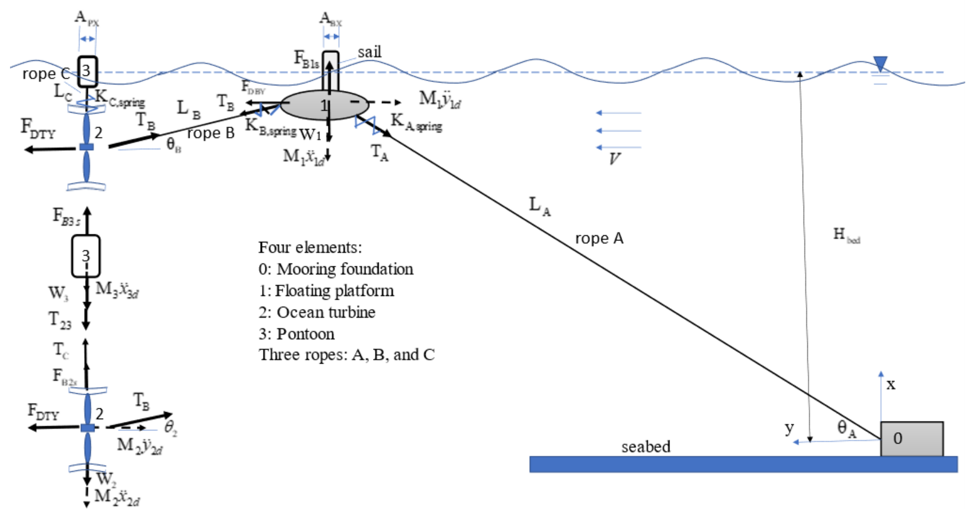
Consider the conditions in Figure 4: (1) the depth of seabed Hbed = 1300 m; (2) the cross-sectional area of surfaced sail of floating platform, ABX = 8 m2; (3) the cross-sectional area of pontoon connecting to turbine, APX = 1 m2; (4) no buffer spring; (5) the ropes 1, 2, and 3 made of some commercial high-strength PE dyneema: Young’s modulus E = 100 GPa, weight per unit length fg = 16.22 kg/m, diameter D = 154 mm, cross-sectional area A = 0.0186 m2, fracture strength Tfracture = 759 tons; (6) the static diving depth of the turbine LC = 60 m; (7) the inclined angle of the rope 2, θ B = 5 ° and the corresponding length LB = 688.4 m; (8) the inclined angle of the rope 1, θ A = 30 ° , and the corresponding length LA = 2600 m; (9) according to Equations (16), (21) and (25), the corresponding effective spring constants of the ropes 1, 2, and 3: K A d = 72.78   tons / m , K B d = 273.4   tons / m , and K C d = 2908   tons / m ; (10) the current velocity V = 1 m/s; (11) the wave height and amplitude HW = 8 m and H0 = 4 m; (12) the masses of the turbine, floating platform, and pontoon: M 1 = 200   tons , M 2 = 650   tons , and M 3 = 10   tons ; (13) the effective masses of rope 1, m e f f , x = 8.546   tons and m e f f , y = 14.8   tons ; (14) the cross-sectional area of floating platform and turbine, A B Y = 23   m 2 and A T Y = 500   m 2 ; (15) the effective damping coefficients, C D y F = 0.3 and C D y T = 8 / 9 ; (16) the static axial force to turbine FDTs = 150 tons. Figure 4a–d demonstrate the effects of wave frequency f and the wave phase ϕ between two devices excited by a wave: (a) the floating platform, (b) the pontoon, on the dynamic tensions of ropes and the dynamic displacements of the floating platform, the pontoon, and the turbine. The relation among the phase ϕ, wave length λ, the distance between floating platform and pontoon L4, and the relative orientation between current and wave α is presented in Equation (12). Obviously, the phase ϕ depends on the distance between the floating platform and pontoon L4.
Figure 4a,b show the effects of wave frequency and phase on the dynamic tensions of ropes 1 and 2. It is found that the resonance frequency f is 0.182 Hz, and the maximum dynamic tensions are T 1 D , max = 148.1   tons and T 2 D , max = 171.5   tons , which is less than the breaking strength Tfracture = 759 tons. Moreover, the effect of phase is significant. When f = 0.182 Hz and ϕ = 0°, 180°, and 360°, the dynamic tensions are maximum. Figure 4c shows that if, ϕ = 0°, 180°, or 360°, the dynamic tension of the rope 3 is under the breaking strength Tfracture. However, for other phases, the dynamic tension is over the breaking strength Tfracture, especially for ϕ~90° or 270°. The maximum tension TCd,max = 11,411 tons. Figure 4d shows the effect of wave frequency on the dynamic displacements x i d and y i d for ϕ = 0° and 90°. Ιt is found that, for ϕ = 0°, the elongation of rope 3, x 3 d x 2 d is very small. Therefore, the corresponding dynamic tension, T C d = K C d x 3 d x 2 d , is small. However, at ϕ = 90°, the elongation of the rope C, x 3 d x 2 d is very large. Therefore, the corresponding dynamic tension is very large. Moreover, it is well known that, if the turbine is more stable, its performance of power generation can be kept high easily. When ϕ = 0°, the amplitudes of dynamic displacement of the turbine are very small. At the resonant wave frequency f = 0.182 Hz, the amplitudes of dynamic displacement of the turbine are x 2 d   = 0.045   m and y 2 d   = 0.240   m . When ϕ = 90°, the amplitudes of dynamic displacement of the turbine are negligible. In other words, this mooring system can keep, effectively, the stability of the turbine.
Because the dynamic tension of rope C is very large, a buffer spring, KC,spring = Krope A, is connected in series with rope C to reduce the effective spring constant to K 23 d = 71.28   tons / m . The other parameters are the same as those in Figure 4. The effect of the buffer spring on the dynamic tensions and displacements is demonstrated in Figure 5. At first, it is found that the two elongations of rope 3, δ = x 3 d x 2 d , at the phase ϕ = 90 ° in Figure 4d and Figure 5d, are very close. This is because the effective spring constant to K C d = 71.28   tons / m , and the corresponding maximum dynamic tension T C d , max = K C d x 3 d x 2 d max = 279.3 tons, which is less than the fracture strength of rope Tfracture = 759 tons, as shown in Figure 5c. In other words, the smaller the effective spring constant KCd is, the smaller the dynamic tension TCd is. Meanwhile, it is found in Figure 5a,b that the effect of the buffer spring on the dynamic tensions of the ropes T A d and T B d is negligible. It is observed in Figure 5d that, when ϕ = 0°, the amplitudes of dynamic displacement of the turbine are very small. At the resonant wave frequency f = 0.182 Hz, the amplitudes of dynamic displacement of the turbine are x 2 d   = 0.046   m and y 2 d   = 0.248   m . When ϕ = 90°, the amplitudes of dynamic displacement of the turbine are negligible.
Figure 6 demonstrates the effect of wave height HW on the maximum dynamic tensions T A d , max ,   T B d , max , and T C d , max in the domains of wave frequency and phase, 0.02 < f ( H z ) < 0.7 and 0 ° < ϕ < 360 ° . The inclined angle of rope 2, θ B = 10 ° . The corresponding length of rope B, LB = 345.5 m. The effective spring constants of the ropes A, B, and C: K A d = 72.78   tons / m , K B d = 540.6   tons / m , K C d = 71.28   tons / m . The other parameters are the same as those in Figure 4. It is found that the larger the wave height HW is, the larger the maximum dynamic tensions are, especially for T B d , max .
Figure 7 demonstrates the effect of the area of pontoon APX on the maximum dynamic tensions T A d , max ,   T B d , max , and T C d , max in the domains of wave frequency and phase 0.02 < f ( H z ) < 0.7 and 0 ° < ϕ < 360 ° . Except the area of pontoon APX, all the parameters are the same as those in Figure 6. It is found that the larger the area of pontoon APX is, the larger the maximum dynamic tensions are, especially for T C d , max .
Figure 8 demonstrates the effect of the cross-sectional area of sail ABX on the maximum dynamic tensions T A d , max ,   T B d , max , and T C d , max in the domains 0.02 < f ( H z ) < 0.7 and 0 ° < ϕ < 360 ° . Except for the cross-sectional area of sail ABX, all the parameters are the same as those in Figure 5. It is found that the larger the cross-sectional area of sail ABX is, the larger the maximum dynamic tensions T A d , max and T B d , max are, especially for T B d , max . However, the effect of the area of sail ABX on the maximum dynamic tensions T C d , max is negligible.
Because the parameters H w , A B X , and A P X are the factors of external excitation, these are not related to the structure of system. The natural frequency of the system does not change with these parameters. It is verified in Figure 4, Figure 5 and Figure 6 that there is no resonant shift during the variation of the parameters.
Figure 9 demonstrates the effect of the inclined angle θ1 of rope 1 on the maximum dynamic tensions T A d , max ,   T B d , max , and T C d , max in the domains 0.02 < f ( H z ) < 0.7 and 0 ° < ϕ < 360 ° . Except for the inclined angle θ1, the corresponding effective masses m e f f , x = 4 f g L 1 sin θ 1 / π 2 and m e f f , y = 4 f g L 1 cos θ 1 / π 2 , and the effective spring constant K C , s p r i n g = K r o p e   A , all the parameters are the same as those in Figure 6. It is found that, if θ A = θ A , i , i = 1 , 2 , , 10 , and the wave frequency is the resonant one and the phase ϕ = 180 o , the dynamic tensions T A d and T B d are over the fracture strength Tfracture. However, if the inclined angle θ A is not in the neighbor of θ A , i , i = 1 , 2 , , 10 , the wave frequency is not the resonant one, or the length L4 is adjusted so that the phase ϕ 180 ° , the dynamic tensions T A d and T B d are less than the fracture strength Tfracture. The larger the inclined angle θ A is, the larger the maximum dynamic tension T C d , max of rope C is. Because the structure of system depends on the inclined angle θ A , the natural frequency of the system changes with the inclined angle θ A . There exists several resonant frequencies, as shown in Figure 9.
Figure 10 demonstrates the effect of the inclined angle θB of the rope B on the maximum dynamic tensions T A d , max ,   T B d , max , and T C d , max in the domains of wave frequency and phase 0.02 < f ( H z ) < 0.7 and 0 ° < ϕ < 360 ° . Except for the inclined angle θ2, the corresponding length of rope 2, L B = L C / sin θ B , and the effective spring constants, K A d = K r o p e   A , K B d = K r o p e   B , and K C , s p r i n g = K r o p e   A , all the parameters are the same as those in Figure 6. It is found that the larger the inclined angle θ B is, the larger the maximum dynamic tensions T A d , max and T B d , max of ropes 1 and 2 are. Moreover, if θ B = θ B , i , i = 2 ~ 5 and the wave frequency is the resonant one and the phase ϕ = 180°, the dynamic tensions T A d and T B d are over the fracture strength Tfracture. However, if the inclined angle θ B is not in the neighbor of θ B , i , i = 2 ~ 5 , and less than 11°, the dynamic tensions T A d and T B d are less than the fracture strength Tfracture. The effect of the inclined angle θ B on the maximum dynamic tension T C d , max of rope C is negligible.
Because the structure of the system depends on the inclined angle θ B , the natural frequency of the system changes with the inclined angle θ B . There exists several resonant frequencies, as shown in Figure 10.
Figure 11 demonstrates the effect of the current velocity V on the maximum dynamic tensions T A d , max ,   T B d , max , and T C d , max in the domains of wave frequency and phase 0.02 < f ( H z ) < 0.7 and 0 ° < ϕ < 360 ° . Except for the inclined angle θ2 = 5°, the corresponding length of rope 2, L B = L C / sin θ B , and the effective spring constants, K A d = K r o p e   A , K B d = K r o p e   B , and K C , s p r i n g = K r o p e   A , all the parameters are the same as those in Figure 5. Obviously, the second terms of Equations (37) and (40) are the damping force, for which the damping coefficient is composed of the parameters: (1) the damping coefficient, (2) the damping area, and (3) the current velocity V. Due to this fact, the natural frequency of the system changes with the current velocity V. Further, there exists several resonant frequencies, as shown in Figure 11. Considering a buffer spring, KC,spring = Krope A, is connected in series with rope C, if V = V i , i = 1 , 2 , 3 and the wave frequency is the resonant one, and the phase ϕ = 180°, the dynamic tensions T A d and T B d are over the fracture strength Tfracture. However, if the current velocity V is not the neighbor of V i , i = 1 , 2 , 3 , the dynamic tensions T A d and T B d are less than the fracture strength Tfracture. The effect of the current velocity V on the maximum dynamic tension T C d , max of rope C is negligible. Further, if two buffer springs are connected in series with ropes B and C, the dynamic tensions T A d and T B d at the resonance are significantly reduced.

5. Conclusions

In this study, the proposed mooring design can keep the turbine stable near some predetermined water depth such that the stability and safety of the ocean current generator can be kept. The linear elastic model of the mooring system is derived. The theoretical solutions of the static and dynamic stability analysis of the system are proposed. In this design, the floating platform and pontoon on the water surface are affected by waves, and there exists a phase difference between the buoyancy forces that is exciting to the two devices. The effect of this phase on the movement of the platform, the pontoon and the turbine, and the tension of the rope is significant. The effects of several parameters on the dynamic response spectrum due to wave excitation are discovered as follows:
(1)
Under the wave excitation, the amplitudes of dynamic displacement of the turbine are very small. In other words, the proposed mooring design can keep the turbine stable;
(2)
The larger the wave height HW is, the larger the maximum dynamic tensions are, especially for T B d , max ;
(3)
The larger the area of pontoon APX is, the larger the maximum dynamic tensions are, especially for T C d , max ;
(4)
The larger the cross-sectional area of sail ABX is, the larger the maximum dynamic tensions T A d , max and T B d , max are, especially for T B d , max . However, its effect on the maximum dynamic tensions T C d , max is negligible;
(5)
The length LD is adjusted so that the phase is not the resonant one, and the dynamic tensions T A d and T B d are less than the fracture strength Tfracture;
(6)
The smaller the effective spring constant KCd is, the smaller the dynamic tension T3D is. However, the effect of the buffer spring on the dynamic tensions of ropes T A d and T B d is negligible;
(7)
The effect of the buffer spring KCd on the resonant dynamic tensions T A d and T B d is significant;
(8)
Moreover, generally speaking, the conditions of waves and ocean currents in ocean current power generation fields are known through long-term observation and investigation. According to the known wave current conditions, the parameters of the mooring system such as rope length and phase angle can be adjusted to avoid the resonance phenomenon to protect the safety and life of the devices and the rope.
These results are significantly helpful for the safety design of mooring systems.

Author Contributions

Conceptualization, S.-M.L. and C.-T.L.; methodology, S.-M.L.; software, S.-M.L.; validation, S.-M.L. and Y.-Y.C.; formal analysis, S.-M.L.; investigation, Y.-Y.C.; resources, Y.-Y.C.; data curation, C.-T.L.; writing—original draft preparation, S.-M.L.; writing—review and editing, C.-T.L.; visualization, S.-M.L.; supervision, S.-M.L.; funding acquisition, S.-M.L. and C.-T.L. All authors have read and agreed to the published version of the manuscript.

Funding

This work was financially supported by the Green Energy Technology Research Center from The Featured Areas Research Center Program within the framework of the Higher Education Sprout Project by the Ministry of Education (MOE) in Taiwan and the National Academy of Marine Research of Taiwan, R. O. C. (NAMR110051).

Institutional Review Board Statement

Not applicable.

Informed Consent Statement

Not applicable.

Data Availability Statement

The figures and the tables in this manuscript have clearly described all the data of this study.

Conflicts of Interest

The authors declare no conflict of interest. The funders had no role in the design of the study; in the collection, analyses, or interpretation of data; in the writing of the manuscript, or in the decision to publish the results.

Appendix A. Theoretical Drag Force of Turbine

The drag force of turbine under uniform current velocity is derived based on Betz’s law as follows:
As shown in Figure A1,
Figure A1. Stream tube, the flow velocity variation and the pressure on the blades of turbine.
Jmse 09 01425 g0a1
According to the Bernoulli principle, the drag of the rotor can be derived as follows: the relation between the specific energies at the sections {0, 1} is
p 0 + ρ 2 V 0 2 = p 1 + ρ 2 V 1 2
where V1 is the speed in the front of the rotor, V2 is the speed downstream of the rotor, ρ is the fluid density. The relation between the specific energies at the sections 1 , 2 is
p 2 + ρ 2 V 2 2 = p 1 + ρ 2 V 1 2
where p2 and V2 are the pressure and speed downstream of the rotor, respectively. Because the effect of rotor is negligible at a long distance from the rotor, the pressure recovers the original one, p 2 = p 0 . Based on the mass conservation and the incompressible flow, one can obtains
V 1 = V 1
According to the relations of pressure and velocity, Equation (A2) becomes
p 0 + ρ 2 V 2 2 = p 1 + ρ 2 V 1 2
The axial force of the blade is
F b l a d e = ( p 1 p 1 ) A b l a d e
where the operational area of the rotor A b l a d e = π R b l a d e 2 in which Rblade is the radius of blade. Assume the ratio of velocity
V 2 = a V 0
Substituting Equations (A1), (A4) and (A6) into (A5), one obtains
F b l a d e = ρ 2 A b l a d e V 0 2 ( 1 a 2 ) C D T y ρ 2 A b l a d e V 0 2
where the theoretical effective drag coefficient C D T y = ( 1 a 2 ) . According to the Betz’s law, if the ratio of velocity a = 1/3, the optimum efficiency of turbine is about 59.26 %. The corresponding drag coefficient C D T y = 8 / 9 is considered in this study, although the coefficient depends significantly on the practical ocean turbine.

References

  1. Chen, Y.Y.; Hsu, H.C.; Bai, C.Y.; Yang, Y.; Lee, C.W.; Cheng, H.K.; Shyue, S.W.; Li, M.S. Evaluation of test platform in the open sea and mounting test of KW Kuroshio power-generating pilot facilities. In Proceedings of the 2016 Taiwan Wind Energy Conference, Keelung, Taiwan, 24–25 November 2016. [Google Scholar]
  2. Lin, S.M.; Chen, Y.Y. Dynamic stability and protection design of a submarined floater platform avoiding Typhoon wave impact. J. Mar. Sci. Eng. 2021, 9, 977. [Google Scholar] [CrossRef]
  3. Lin, S.M.; Chen, Y.Y.; Hsu, H.C.; Li, M.S. Dynamic Stability of an Ocean Current Turbine System. J. Mar. Sci. Eng. 2020, 8, 687. [Google Scholar] [CrossRef]
  4. IHI; NEDO. The Demonstration Experiment of the IHI Ocean Current Turbine Located off the Coast of Kuchinoshima Island, Kagoshima Prefecture, Japan, 14 August 2017. Available online: https://tethys.pnnl.gov/project-sites/ihi-ocean-current-turbine (accessed on 28 August 2021).
  5. Zwieten, J.V.; Driscoll, F.R.; Leonessa, A.; Deane, G. Design of a prototype ocean current turbine—Part I: Mathematical modeling and dynamics simulation. Ocean. Eng. 2006, 33, 1485–1521. [Google Scholar]
  6. Xiang, G.; Xu, S.; Wang, S.; Soares, C.G. Advances in Renewable Energies Offshore: Comparative Study on Two Different Mooring Systems for a Buoy; Taylor & Francis Group: London, UK, 2019; pp. 829–835. [Google Scholar]
  7. Cerveira, F.; Fonseca, N.; Pascoal, R. Mooring system influence on the efficiency of wave energy converters. Int. J. Mar. Energy 2013, 3, 65–81. [Google Scholar] [CrossRef]
  8. Paduano, B.; Giorgi, G.; Gomes, R.P.F.; Pasta, E.; Henriques, J.C.C.; Gato, L.M.C.; Mattiazzo, G. Experimental Validation and Comparison of Numerical Models for the Mooring System of a Floating Wave Energy Converter. J. Mar. Sci. Eng. 2020, 8, 565. [Google Scholar] [CrossRef]
  9. Angelelli, E.; Zanuttigh, B.; Martinelli, L.; Ferri, F. Physical and numerical modelling of mooring forces and displacements of a Wave Activated Body Energy Converter. In Proceedings of the ASME 2014 33rd International Conference on Ocean, Offshore and Arctic Engineering, San Francisco, CA, USA, 8–13 June 2014; p. V09AT09A044. [Google Scholar]
  10. Chen, D.; Nagata, S.; Imai, Y. Modelling wave-induced motions of a floating WEC with mooring lines using the SPH method. In Proceedings of the 3rd Asian Wave and Tidal Energy Conference, Marina Bay Sands, Singapore, 25–27 October 2016; pp. 24–28. [Google Scholar]
  11. Davidson, J.; Ringwood, J.V. Mathematical Modelling of Mooring Systems for Wave Energy Converters—A Review. Energies 2017, 10, 666. [Google Scholar] [CrossRef] [Green Version]
  12. Muliawan, M.J.; Gao, Z.; Moan, T. Application of the Contour Line Method for Estimating Extreme Responses in the Mooring Lines of a Two-Body Floating Wave Energy Converter. J. Offshore Mech. Arct. Eng. 2013, 135, 031301. [Google Scholar] [CrossRef]
  13. Touzon, I.; Nava, V.; Miguel, B.D.; Petuya, V. A Comparison of Numerical Approaches for the Design of Mooring Systems for Wave Energy Converters. J. Mar. Sci. Eng. 2020, 8, 523. [Google Scholar] [CrossRef]
  14. Hoeg, C.; Zhang, Z. The influence of different mooring line models on the stochastic dynamic responses of floating wind turbines. J. Phys. Conf. Ser. 2018, 1037, 062016. [Google Scholar] [CrossRef]
  15. Lin, S.M.; Lee, K.W. Instability and vibration of a vehicle moving on curved beams with different boundary conditions. Mech. Adv. Mater. Struct. 2016, 23, 375–384. [Google Scholar] [CrossRef]
  16. Lin, S.M. Nonlinear vibration control of a tall structure with tuned liquid column damper. Mech. Adv. Mater. Struct. 2016, 23, 146–155. [Google Scholar] [CrossRef]
  17. Lin, S.M.; Teng, M.J. Vibration control and separation of a device scanning an elastic plate. Comp. Mod. Eng. Sci. 2014, 103, 189–213. [Google Scholar]
  18. Lin, S.M. Nonlinear vibration of the double-beams assembly subjected to a.c. electrostatic force. Comp. Mod. Eng. Sci. 2010, 60, 95–114. [Google Scholar]
  19. Lin, S.M. Effective dampings and frequency shifts of several modes of an inclined cantilever vibrating in viscous fluid. Precis. Eng. 2010, 34, 320–326. [Google Scholar] [CrossRef]
  20. Bek, M.A.; Amer, T.S.; Sirwah, M.A.; Awrejcewicz, J.; Arab, A.A. The vibrational motion of a spring pendulum in a fluid flow. Results Phys. 2020, 19, 103465. [Google Scholar] [CrossRef]
  21. Amer, W.S.; Farag, A.M.; Abady, I.M. Asymptotic analysis and numerical solutions for the rigid body containing a viscous liquid in cavity in the presence of gyrostatic moment. Arch. Appl. Mech. 2021, 91, 3889–3902. [Google Scholar] [CrossRef]
  22. Central Weather Bureau of the Ministry of Communications of the Republic of China. Monthly Wave Height Statistics of Taitung Foreign Ocean Buoy (2009–2020). Available online: https://www.cwb.gov.tw/V8/C/C/MMC_STAT/sta_wave.html (accessed on 10 September 2021).
Figure 1. Coordinates of the current energy system composed of submarined ocean turbine, pontoon, floating platform, traction rope, and mooring foundation in a static state under steady ocean current.
Jmse 09 01425 g001
Figure 2. Coordinates of the current energy system composed of submarined ocean turbine, pontoon, floating platform, traction rope, and mooring foundation in a dynamic state under steady ocean current and wave.
Jmse 09 01425 g002
Figure 3. Relation among phase ϕ, wave length λ, and relative direction α of wave, current, and distance L4 between turbine and floating platform.
Jmse 09 01425 g003
Figure 4. Effects of the wave frequency f and the phase ϕ on the dynamic response of the system. (a) Effects of the wave frequency f and the phase ϕ on the dynamic tension of rope T A d . (b) Effects of the wave frequency f and the phase ϕ on the dynamic tension of rope T B d . (c) Effects of the wave frequency f and the phase ϕ on the dynamic tension of rope T C d . (d) Effects of the wave frequency f and the phase ϕ on the dynamic displacements x 1 d , x 2 d , x 3 d , y 1 d , y 2 d .
Jmse 09 01425 g004
Figure 5. Effects of the buffer spring C, the wave frequency f, and the phase ϕ on the dynamic response of the system. (a) Effects of the buffer spring C, the wave frequency f, and the phase ϕ on the dynamic tension of rope T A d . (b) Effects of the buffer spring C, the wave frequency f, and the phase ϕ on the dynamic tension of rope T B d . (c) Effects of the buffer spring C, the wave frequency f, and the phase ϕ on the dynamic tension of rope T C d . (d) Effects of the buffer spring C, the wave frequency f, and the phase ϕ on the dynamic displacements x 1 d , x 2 d , x 3 d , y 1 d , y 2 d .
Jmse 09 01425 g005aJmse 09 01425 g005b
Figure 6. Effects of wave height HW on the maximum dynamic tensions of ropes T A d , max , T B d , max , T C d , max in the domains of wave frequency and phase, 0.02 < f ( H z ) < 0.7 and 0 ° < ϕ < 360 ° .
Jmse 09 01425 g006
Figure 7. Effects of pontoon cross-sectional area APX on the maximum dynamic tensions of ropes T A d , max ,   T B d , max , and T C d , max in the domains of wave frequency and phase 0.02 < f ( H z ) < 0.7 and 0 ° < ϕ < 360 ° .
Jmse 09 01425 g007
Figure 8. Effects of sail’s cross-sectional area ABX on the maximum dynamic tensions of ropes T A d , max ,   T B d , max , and T C d , max in the domains of wave frequency and phase 0.02 < f ( H z ) < 0.7 and 0 ° < ϕ < 360 ° .
Jmse 09 01425 g008
Figure 9. Effect of the inclined angle θA on the maximum dynamic tensions of ropes T A d , max ,   T B d , max , and T C d , max in the domains of wave frequency and phase 0.02 < f ( H z ) < 0.7 and 0 0 < ϕ < 360 0 .
Jmse 09 01425 g009
Figure 10. Effect of the inclined angle θB on the maximum dynamic tensions of ropes T A d , max ,   T B d , max , and T C d , max in the domains of wave frequency and phase 0.02 < f ( H z ) < 0.7 and 0 0 < ϕ < 360 0 .
Jmse 09 01425 g010
Figure 11. Effect of the current velocity V on the maximum dynamic tensions of ropes T A d , max ,   T B d , max , and T C d , max in the domains of wave frequency and phase 0.02 < f ( H z ) < 0.7 , and 0 0 < ϕ < 360 0 .
Jmse 09 01425 g011
Publisher’s Note: MDPI stays neutral with regard to jurisdictional claims in published maps and institutional affiliations.

