Abstract
This paper discusses the concept and practicality of internet-of-things (IoT) link security enhancements using multiple-input multiple-output (MIMO) and beamforming solutions at the physical layer of the wireless system. Large-scale MIMO and beamforming techniques have been studied extensively in the context of 5G cellular systems. The concept of utilizing these transmission techniques for security enhancements in cellular IoT systems, however, have not yet been fully explored. This article will list a variety of options that may be explored in realizing more secure IoT links using MIMO-beamforming techniques. The paper provides a valuable tutorial for both engineers and researchers working in this field.
1. Introduction
Fifth-generation (5G) cellular networks were recently rolled out with performance metrics that are highly desirable in military communications, such as low latency and ultra-high data rates. The department of defense (DoD) is currently testing 5G cellular networks for logistics, smart warehousing, spectrum sharing, training exercises, battlefield commands and control (C2), and security [1,2,3]. Support for specialized military equipment, such as unmanned ground vehicles (UGVs) and battlefield C2, can be provided via the IoT and cutting-edge protocols in the cellular architecture. However, these are not currently designed for military-grade communications regarding either physical layer (PHY) access or the core network. Therefore, future cellular standards must incorporate military-specific communication protocols that will enable military-grade security and privacy to enable the military to take full advantage of Next-G cellular networks [4]. This paper focuses on MIMO-beamforming techniques, which can be used to enhance the security of cellular IoT links for military application. We discuss the use of reconfigurable beams from MIMO-beamforming arrays at 60 GHz as a means of realizing secure and covert wireless links for military IoT systems. This discussion will focus on the lossy 60-GHz mmWave bands, due to its unique lossy characteristics.
PHY security has gained significant attention lately, both in the contexts of the terrestrial 5G cellular networks and the satellite systems. In [5], a comprehensive survey of PHY security techniques for satellite communications was presented. In [6], the security–reliability tradeoff that exists when using cooperative non-orthogonal multiple access (NOMA) techniques in terrestrial mobile communication networks was considered. Large-scale MIMO and beamforming techniques have also been studied extensively in the context of 5G cellular systems [7,8]. The 60 GHz millimeter (mmWave) band has been characterized fairly well in studies we have examined [9,10,11]. However, the idea of exploring the lossy nature of the 60 GHz band to realize secure and covert military communication links is novel [4]. In such systems, the limited range of 60 GHz links, due to severe loss, will be turned into an advantage to realize secure radio communications over a short range. Several challenges are to be addressed, however, in order to enable the wireless communications community to develop appropriate techniques that can be used to engineer such a system. Adaptive tuning of radio beams to different angles during an ongoing communication between a transmitter (TX) and receiver (RX) is well-established in [7]. It has also been shown recently, in 5G cellular networks, that radio capacity is significantly enhanced when directional beams from massive MIMO systems are utilized. In this paper, we demonstrate how PHY secrecy and privacy is achievable when MIMO-beamforming is employed over a 60 GHz radio band. This will help address a vital requirement in the design specifications for military IoT systems that current cellular IoT links lack—secrecy and privacy [12,13,14].
2. MIMO-Beamforming Techniques for PHY Security
2.1. Sub-Band Tunable Beamforming
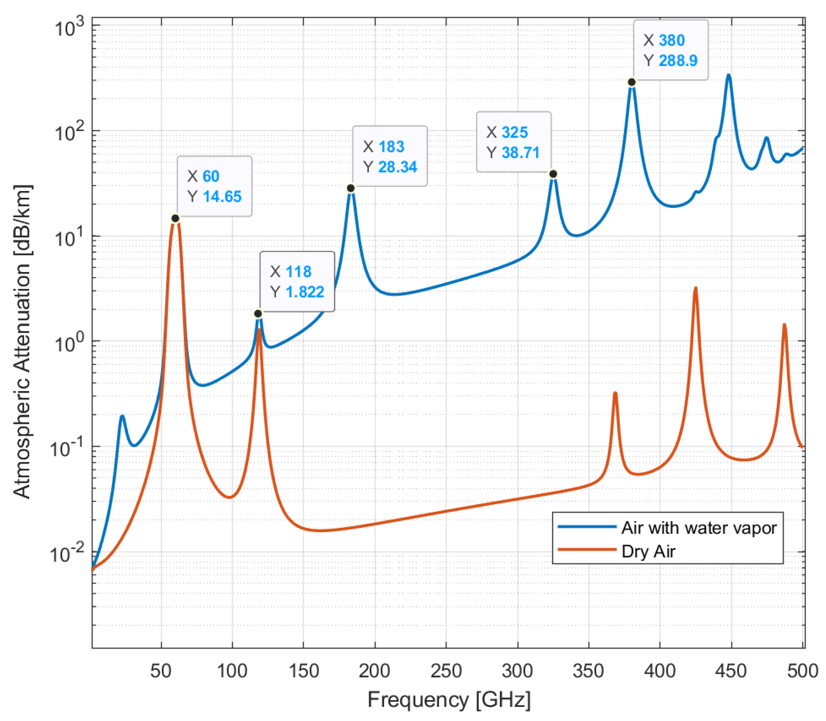
Sub-band adaptive beamforming techniques can be exploited for PHY security by employing rapidly reconfigurable beams over sub-bands in secure mmWave frequencies, such as 60 GHz. In Figure 1, we display the atmospheric attenuation at the mmWave radio spectrum in the presence of water vapor density of 7.5 , in comparison with atmospheric attenuation in dry air (zero water vapor density). The figure also displays the peak attenuation values for the case of lossy air with water vapor. These bands are referred to in this paper as secure mmWave bands. The curves in this figure were computed based on the ITU-R document P.676-12 [15].
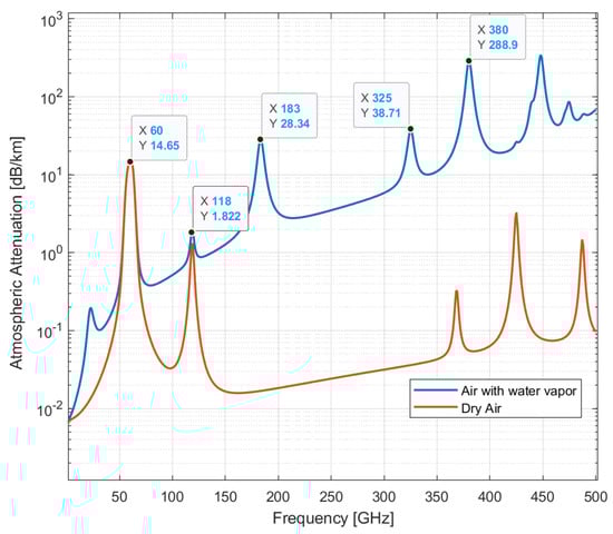
Figure 1.
Specific atmospheric attenuation for 1 to 500 GHz for an atmospheric pressure of 101.300 kPa and a temperature of 15 °C.
As shown in Figure 1, the 60 GHz band is highly lossy and radio transmission in the band is limited to a few meters between the transmitter and receiver. For added security enhancement in cellular IoT links, radio transmissions can be tuned in a pseudo-random or deterministic manner over several sub-bands centered at 60 GHz. Since these sub-bands are very lossy, coding techniques that can assure link reliability in lossy channels must be deployed alongside MIMO-beamforming.
2.2. Tunable Beamforming Circuits
Tunable beamforming circuits can be developed for adaptive tuning of radio links from one secure sub-band to another, with operations centered at the 60 GHz frequency. Two important challenges to be discussed in such work are the optimization of the beamforming weights for various frequencies , and the technique for developing communication circuits with capabilities for adaptive tuning of radio links over a few sub-bands centered around the 60 GHz frequency. The setup for such a system is illustrated in Figure 2.
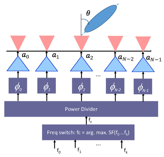
Figure 2.
Diagram of an N-Element tunable beamforming circuit to be developed.
Let denote the complex beamforming weights, representing the amplifier gains and phase shifter settings for each element of the array in Figure 2 as it forms directed beams at an angle . Then, the issue of optimization rests in solving the weights, , maximizing link security and privacy, as well as link reliability at each of the sub-bands in the 60 GHz frequency. This is required at both the TX and RX side of the radio link, resulting in a multiple-input multiple-output (MIMO) beamforming system. Tuning of the beamforming coefficients, , is realized by controlling the steering vector , and the phase-shift vector . To ensure the security and privacy of IoT links, the array parameters and can be chosen to realize directed pencil beams to the intended receivers. The resulting array gain will dictate the power radiated by the beamforming array and the distance, , within which a received signal level above the sensitivity () of the communication receiver determines the intended useful communication range, while the distance, , in which the received signal level is below can be used to determine the maximum intercept range beyond which eavesdropping becomes practically impossible since most practical communication receivers cannot detect signal levels hundreds of times below their sensitivity. These parameters can be used to design secure IoT links, where communications between the TX and RX are kept secure and private. The secrecy capacity (SC) for such a wireless system is calculated as:
where denotes the information capacity of the TX-RX link, denotes the information capacity of the TX-Evedropper link. It can be shown that SC is maximized, practically, at distances beyond the intercept range, .
2.3. Adaptive Tuning of Radios for Secure IoT Links
The adaptive tuning of radio links between the TX and RX can be conducted either in a pseudo-random or deterministic manner using banks of phased array setup shown in Figure 2. The frequency switching block will select a particular sub-band in the 60 GHz frequency to be used at any time. For pseudo-random switching, the goal is to maximize PHY secrecy by changing the frequency of the communication link between the TX and RX several times during the communication, in a pseudo-random manner understood by both the TX and legitimate RX. Thus, if a third-party device were to eavesdrop on a particular frequency, it would only detect a portion of the message, which could also be encrypted. By minimizing the length of time that the TX and RX operate over a particular sub-band, PHY security can be maximized for IoT links. This approach will rely on the implementation of appropriate coding schemes to combat lossy links that would be encountered in the 60 GHz band. For the deterministic switching approach, the goal is to tune the radio link over a subset of the sub-band that maximizes a defined secrecy function, .
3. Results and Discussions
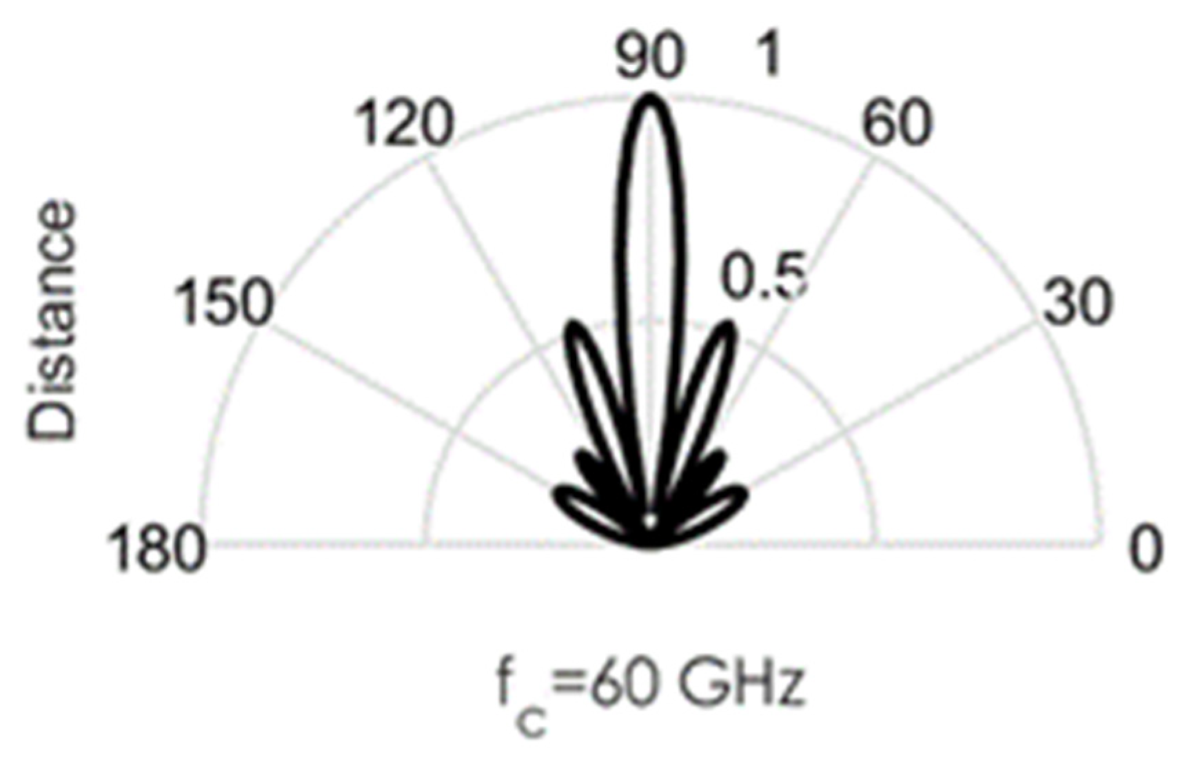
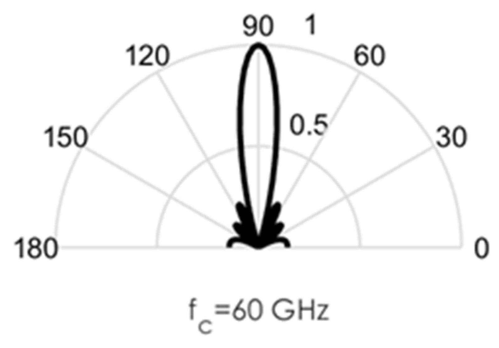
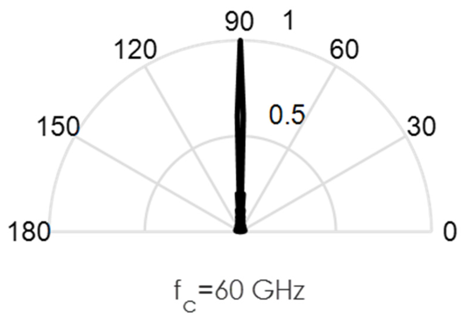
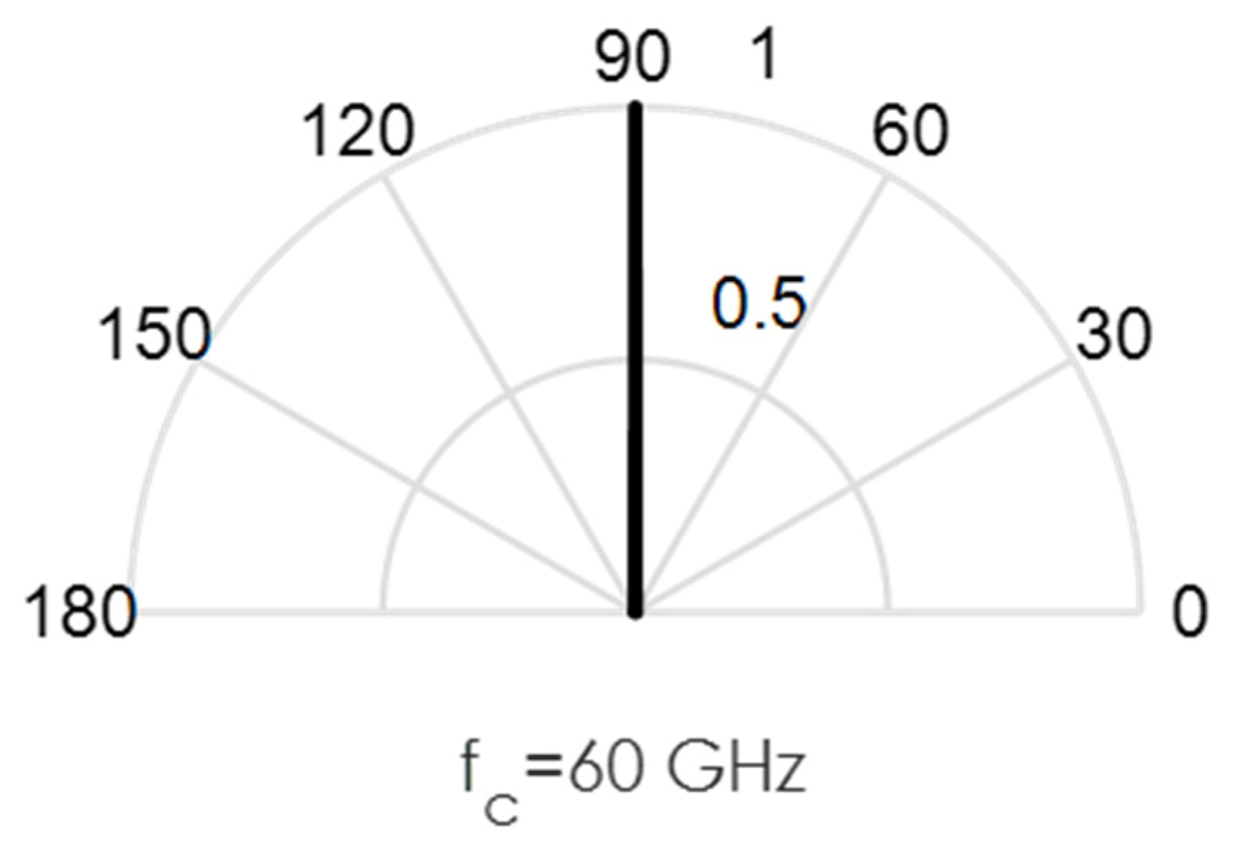
As an illustration of the challenges involved in the design of this circuit, we conducted some MATLAB simulations. Directional beams simulated at 60 GHz mmWave bands using Uniform Linear Arrays (ULA) are shown in Figure 3, Figure 4, Figure 5, Figure 6 and Figure 7. Assuming an array with a physical size of 5 cm 5 cm, /2—spacing implies array elements up to N = 400 at 60 GHz for this array size. Military devices have a fixed physical area, regardless of the frequency of operation. This allows for more array elements at higher frequencies, thus increasing the directivity and security of the communication link. However, the beamforming weights computed at a particular sub-band must be reoptimized for use in another sub-band, in order to minimize energies in the sidelobes. Sidelobes result in signal leakage to unintended receivers, and thus, compromises secrecy. For the simulations in Figure 3, Figure 4, Figure 5, Figure 6 and Figure 7, we observed the effects of steering vector on the resulting beam. For the results shown in Figure 3, an 8-element array is used with the steering vector A = [4 3 2 1 1 2 3 4]. This steering vector is not optimized, hence significant sidelobes are generated in addition to the main beam. For the results in Figure 4, an 8-element array is used with the steering vector A = [1 1 1 1 1 1 1 1]. The steering vector is optimized in this case. An optimum beamformer allocates equal power to all the array elements (as performed in this figure), in the absence of channel state information at the transmitter. Hence, the resulting sidelobes are very small, but still noticeable. For the results in Figure 5, a 12-element array is used with the steering vector A = [1 1 1 1 1 1 1 1 1 1 1 1]. The steering vector is also optimized in this case, and a narrower beam is also generated due to the increase in the number of array elements. This produces a more secure radio link for IoT systems. For the increased secrecy and link privacy required for military use, we further increase the array element to N = 40 and N = 400. The maximum number of array elements, N, possible while still maintaining /2—spacing in an array sized 5 cm 5 cm is N = 400 at 60 GHz. Figure 6 displays the resulting pencil beam generated for N = 40, while Figure 7 displays the corresponding results for the case N = 400. There is virtually no sidelobe generated at N = 400, but beams produced from N = 40 up to N = 400 will all be highly directional as illustrated in these two figures. Such beams ensure that the TX-RX communication link is highly secure and private.
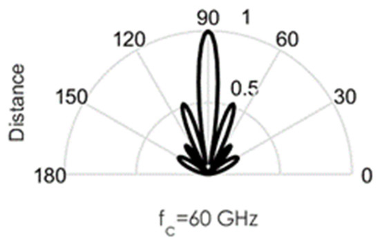
Figure 3.
Directional beams produced by Uniform Linear arrays (ULA) operating at 60 GHz; 8 array elements with /2-spacing; steering vector A = [4 3 2 1 1 2 3 4].

Figure 4.
Directional beams produced by uniform linear arrays (ULA) operating at 60 GHz; 8 array elements with /2-spacing; steering vector A = [1 1 1 1 1 1 1 1].
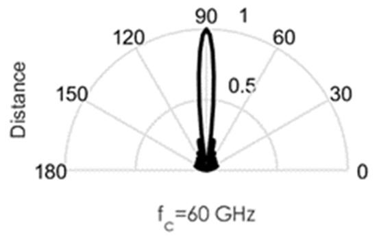
Figure 5.
Directional beams produced by uniform linear arrays (ULA) operating at 60 GHz; 12 array elements with /2-spacing; steering vector A = [1 1 1 1 1 1 1 1 1 1 1 1].
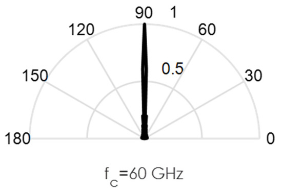
Figure 6.
Directional beams produced by uniform linear arrays (ULA) operating at 60 GHz; 40 array elements with /2-spacing; 40 × 1 steering vector A = [1 1 1 … 1].

Figure 7.
Directional beams produced by uniform linear arrays (ULA) operating at 60 GHz; 400 array elements with /2-spacing; 400 × 1 steering vector A = [1 1 1 … 1].
The problem of optimum beamforming weighting vectors that maximize radio capacity in the OFDM-SDMA system was addressed in [16], where an adaptive algorithm was developed for computing the optimum beamforming weights, , that maximizes channel capacity in a multi-user OFDM-SDMA system using gradient descent method. The performance of the channel capacity-aware beamforming algorithm was shown to achieve substantially higher system capacity compared to the eigen-beamforming design. This is due to the fact that the algorithm directly maximizes the channel capacity criterion for each user iteratively. Similarly, in this paper, MIMO-beamforming designs that seek to maximize PHY security and privacy are explored for the secure 60 GHz mmWave band.
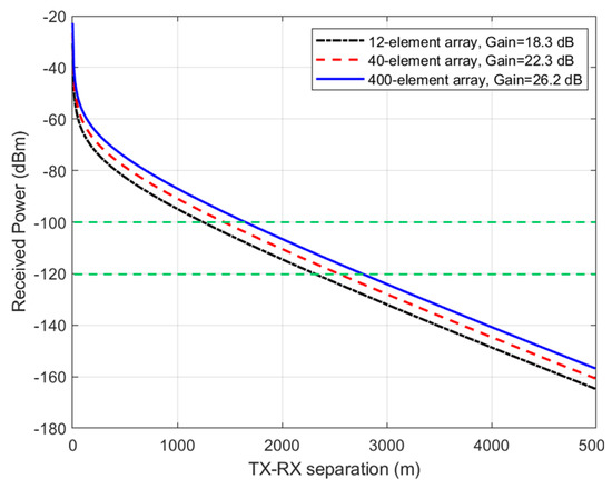
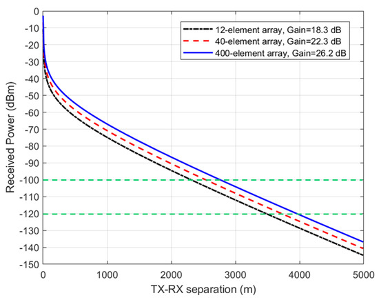
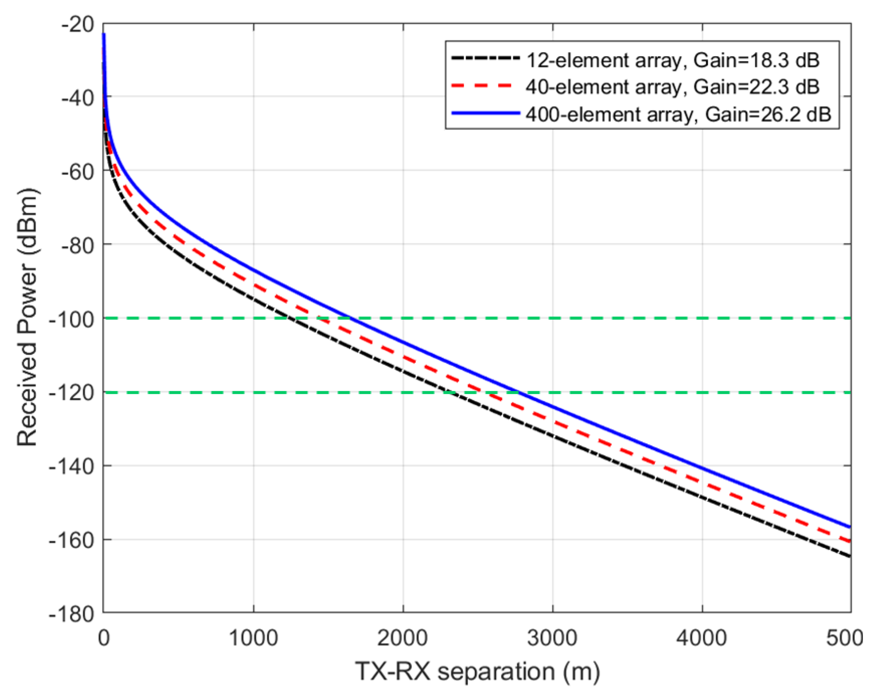
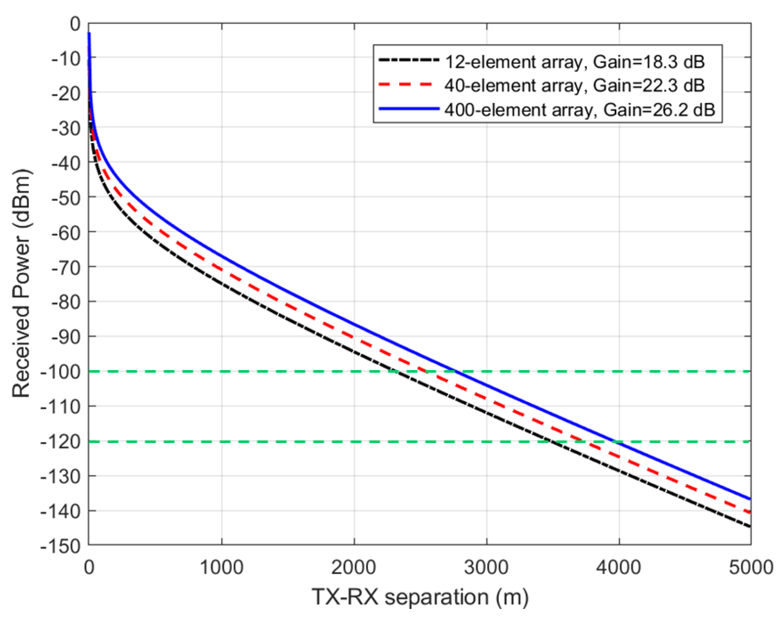
The performance metrics explored for measuring communication secrecy in this paper is the TX-RX range for which eavesdropping is no longer possible. Next, we examine the range of secure communications between TX and RX that is achievable when using the beamforming arrays shown in Figure 5, Figure 6 and Figure 7. We assume typical 5G user equipment (UE) with a transmitted power of 23 dBm (or 200 mW) [17], a base station (BS) with a transmitted power of 43 dBm (or 20 W) [18], and a receiver sensitivity of −100 dBm (or 0.1 pW), considered the same for both the BS and UE, for simplicity. Thus = 0.001 pW = −120 dBm. The Stanford University interim (SUI) model was assumed for the path loss model (terrain type A or hilly/dense vegetation) [18], and water vapor absorption of 14.6 dB/km for the 60 GHz band shown in Figure 1 was added to the terrain-specific path loss. Figure 8 displays the received power as a function of the TX-RX separation distance, when a UE transmits 23 dBm (200 mW) power at 60 GHz using the antenna arrays in Figure 5, Figure 6 and Figure 7 corresponding to antenna gains of 18.3, 22.3, and 26.2, respectively. It can be observed from this figure that the useful transmission range for of −100 dBm is roughly 1.5 km, while the maximum intercept range for 0.01 of −120 dBm is roughly 2.5 km. Figure 9 displays the received power as a function of the TX-RX separation distance, when a BS transmits 43 dBm (20 W) power at 60 GHz using the antenna arrays in Figure 5, Figure 6 and Figure 7 corresponding to antenna gains of 18.3, 22.3, and 26.2, respectively. It can be observed from this figure that the useful transmission range for of −100 dBm is roughly 2.5 km, while the maximum intercept range for 0.01 of −120 dBm is roughly 4 km. These results are important technical contributions. They provide useful guides on the range of secure transmissions that are possible when deploying IoT devices employing beamforming arrays at 60 GHz, assuming that one is operating within contemporary TX and RX parameters stipulated in 5G cellular networks.
4. Conclusions
In this paper, we have illustrated methods for the design of MIMO-beamforming systems for PHY security enhancements in cellular IoT links. Simulation results were presented for directed beams generated by a 5 cm 5 cm ULA, with /2—spacing, for 12, 40, and 400 elements among others. Results show that highly directed or pencil beams can be formed with antenna elements as few as 40, but 400 elements achieve the highest directivity or gain. The secure useful transmission range, as well as the intercept range possible when employing these beamforming arrays, were estimated using contemporary UE and BS parameters, as it is currently specified in 4G/5G cellular systems. These results provide a useful guide as to the range of secure transmissions possible when deploying IoT devices employing beamforming arrays.
Author Contributions
Conceptualization, A.I.S.; formal analysis, A.I.S. and C.H.; investigation, writing—original draft preparation, A.I.S. and C.H.; writing—review and editing, A.I.S. and C.H. All authors have read and agreed to the published version of the manuscript.
Funding
This research was funded by an internal research grant from Embry-Riddle Aeronautical University.
Acknowledgments
The authors thank the anonymous reviewers for their useful comments.
Conflicts of Interest
The authors declare no conflict of interest.
References
- Tadjdeh, Y. Defense Department Further Accelerating 5G Development. Natl. Def. 2021, 105, 22–23. [Google Scholar]
- Martin, M.J.; Kidd, S.R.; Landis, C.B. 5G Technology: Improved Capabilities Enable Joint Logistics for the Future Joint Force: Army Logistician. Army Sustain. 2020, 52, 74–79. [Google Scholar]
- Hoehn, J.R.; Sayler, K.M. National Security Implications of Fifth Generation (5G) Mobile Technologies. Congr. Res. Serv. 2021, 15, F11251. [Google Scholar]
- Harvey, J.; Steer, M.B.; Rappaport, T.S. Exploiting High Millimeter Wave Bands for Military Communications, Applications and Design. IEEE Access 2019, 7, 52350–52359. [Google Scholar] [CrossRef]
- Li, B.; Fei, Z.; Zhou, C.; Zhang, Y. Physical layer security in space information networks: A survey. IEEE Internet Things J. 2020, 7. [Google Scholar] [CrossRef]
- Li, B.; Qi, X.; Huang, K.; Fei, Z.; Zhou, F.; Hu, R.Q. Security-reliability tradeoff analysis for cooperative NOMA in cognitive radio networks. IEEE Trans. Commun. 2019, 67, 83–96. [Google Scholar] [CrossRef]
- Seifi, N.; Heath, R.W., Jr.; Coldrey, M.; Svensson, T. Adaptive Multicell 3-D Beamforming in Multiantenna Cellular Networks. IEEE Trans. Vehicular Technol. 2016, 65, 6217–6231. [Google Scholar] [CrossRef] [Green Version]
- Guo, C.; Shu, C.; Huang, F.; Sun, T.; Tian, L.; Hong, W. Design and Implementation of A Highly Integrated 8-Channel Transceiver for Massive MIMO in 5G. In Proceedings of the 2018 International Conference on Microwave and Millimeter Wave Technology (ICMMT), Chengdu, China, 7–11 May 2018. [Google Scholar]
- Sulyman, A.I.; Alwarafy, A.; MacCartney, G.R.; Samimi, M.K.; Rappaport, T.S.; Alsanie, A. Directional Radio Propagation Path Loss Models for Millimeter-Wave Wireless Networks in the 28, 60, and 73 GHz Bands. IEEE Trans. Wirel. Commun. 2016, 15, 6939–6947. [Google Scholar] [CrossRef]
- Sulyman, A.I.; Alwarafy, A.; Seleem, H.E.; Humadi, K.; Alsanie, A. Effects of Solar Radio Emissions on Outdoor Propagation Path Loss Models at 60 GHz Bands for Access/Backhaul Links and D2D Communications. IEEE Trans. Antennas Propag. 2017, 65, 6624–6635. [Google Scholar] [CrossRef]
- Ben-Dor, E.; Rappaport, T.S.; Qiao, Y.; Lauffenburger, S.J. Millimeter-Wave 60 {GH}z Outdoor and Vehicle {AOA} Propagation Measurements Using a Broadband Channel Sounder. In Proceedings of the 2011 IEEE Global Telecommunications Conference (GLOBECOM 2011), Houston, TX, USA, 5–9 December 2011. [Google Scholar]
- Sulyman, A.I.; Oteafy, S.; Hassanein, H. Expanding the Cellular-IoT Umbrella: An Architectural Approach. IEEE Wireless Commun. 2017, 24, 66–71. [Google Scholar] [CrossRef]
- Sulyman, A.I.; Montano, T.J.; Post, J.E. Experimental Data on Connecting Proprietary IoT Systems to the Cellular IoT Networks. In Proceedings of the 2019 IEEE International Conference on Communications Workshops (ICC Workshops), Shanghai, China, 20–24 May 2019. [Google Scholar]
- Alwarafy, A.; Al-Thelaya, K.A.; Abdallah, M.; Schneider, J.; Hamdi, M. A survey on Security and Privacy Issues in Edge-Computing-Assisted Internet of Things. IEEE Internet Things J. 2021, 8, 4004–4022. [Google Scholar] [CrossRef]
- Radio Communication Sector of ITU (ITU-R). Attenuation by Atmospheric Gases. Recommendation Document ITU-R P.676-12, Aug. 2019. Available online: https://itu-rpy.readthedocs.io/en/latest/apidoc/itu676.html# (accessed on 5 February 2022).
- Sulyman, A.I.; Hefnawi, M. Adaptive MIMO Beamforming Algorithm Based on Gradient Search of the Channel Capacity in OFDM-SDMA Systems. IEEE Commun. Lett. 2008, 12, 642–644. [Google Scholar] [CrossRef]
- Joshi, P.; Ghasemifard, F.; Colombi, D.; Tornevik, C. Actual Output Power Levels of User Equipment in 5G Commercial Networks and Implications on Realistic RF EMF Exposure Assessment. IEEE Access 2020, 8, 204068–204075. [Google Scholar] [CrossRef]
- Sulyman, A.I.; Nassar, A.T.; Samimi, M.K.; MacCartney, G.R.; Rappaport, T.S.; Alsanie, A. Radio propagation path loss models for 5G cellular networks in the 28 GHz and 38 GHz millimeter-wave bands. IEEE Commun. Mag. 2014, 52, 78–86. [Google Scholar] [CrossRef]


Publisher’s Note: MDPI stays neutral with regard to jurisdictional claims in published maps and institutional affiliations. |
© 2022 by the authors. Licensee MDPI, Basel, Switzerland. This article is an open access article distributed under the terms and conditions of the Creative Commons Attribution (CC BY) license (https://creativecommons.org/licenses/by/4.0/).