Article

Eye-Tracking System with Low-End Hardware: Development and Evaluation

1
Department of Computer, Control and Management Engineering, Sapienza University of Rome, 00185 Roma, Italy
2
Institute for Systems Analysis and Computer Science, Italian National Research Council, 00185 Roma, Italy
3
Department of Psychology, Sapienza University of Rome, 00185 Roma, Italy
4
Department of Computational Intelligence, Czestochowa University of Technology, 42-201 Czestochowa, Poland
*
Author to whom correspondence should be addressed.
Information 2023, 14(12), 644; https://doi.org/10.3390/info14120644
Submission received: 24 October 2023 / Revised: 27 November 2023 / Accepted: 28 November 2023 / Published: 1 December 2023
(This article belongs to the Section Biomedical Information and Health)

Abstract

:
Eye-tracking systems have emerged as valuable tools in various research fields, including psychology, medicine, marketing, car safety, and advertising. However, the high costs of the necessary specialized hardware prevent the widespread adoption of these systems. Appearance-based gaze estimation techniques offer a cost-effective alternative that can rely solely on RGB cameras, albeit with reduced accuracy. Therefore, the aim of our work was to present a real-time eye-tracking system with low-end hardware that leverages appearance-based techniques while overcoming their drawbacks to make reliable gaze data accessible to more users. Our system employs fast and light machine learning algorithms from an external library called MediaPipe to identify 3D facial landmarks. Additionally, it uses a series of widely recognized computer vision techniques, like morphological transformations, to effectively track eye movements. The precision and accuracy of the developed system in recognizing saccades and fixations when the eye movements are mainly horizontal were tested through a quantitative comparison with the EyeLink 1000 Plus, a professional eye tracker. Based on the encouraging registered results, we think that it is possible to adopt the presented system as a tool to quickly retrieve reliable gaze information.

1. Introduction

The eye-tracking problem has always attracted the attention of a high number of researchers. Discovering where a person is looking gives insight into their cognitive processes and can help understand what their desires, needs, and emotional states are. Since 1879, when Louis Emile Javal discovered fixations (when the eye gaze is fixed in place so that the visual system can take in detailed information about what is being looked at) and saccades (eye movement between two fixations that is used to shift the eye gaze from one point of interest to another) through naked-eye observations of the eyes’ movement [1], a huge number of applications for tracking the eyes’ movement have been designed. The more technology advances, the more fields of research (i.e., psychology, medicine, marketing, advertisement, human–computer interaction, and so on) have started to use eye trackers.

1.1. Exploring the Applications of Human Eye Attention

One of the most common and important cognitive processes analyzed thanks to the use of eye trackers is attention [2,3,4]. In particular, in psychology and medicine, the analysis of attention can be useful to infer notions about human behavior, to predict the outcome of an intelligence test, or to analyze the cognitive functioning of patients with neurological diseases. For instance, in [5], the effects of computerized eye-tracking training to improve inhibitory control in ADHD (Attention Deficit Hyperactivity Disorder) children are shown. According to [6,7], there were about 6.1 million (9.4%) children (aged from 2 to 17 years old) affected by ADHD in the U.S. Apart from the medical field, eye-tracking techniques are even largely used by marketing groups to perform attention analyses with the aim of creating effective designs in advertising or by usability researchers to define the optimum user experience of web apps. For example, in [8], different website pages have been compared by analyzing heat maps of the screen in order to find the main design elements or structures that can increase usability. Moreover, the study of attention is also very important for people’s safety while driving. As mentioned in [9], in a survey about the use of eye trackers for analyzing distractions that affect people while driving, 90% of the information needed for driving derives from the visual channel, and the main cause of critical situations that potentially lead to a traffic accident derives directly from the drivers themselves. Therefore, improving the ability to recognize when drivers get distracted may drastically improve driving safety and consequently reduce the number of car crashes and their related deaths (in 2018, car crashes caused the deaths of about 1.35 million people worldwide).

1.2. Motivation for Building Our Eye-Tracking System

In consideration of the high number of possible relevant applications deriving from the study of attention, a lot of eye-tracking techniques have been developed over the years. Nevertheless, even nowadays, the majority of these techniques use expensive tools and hardware, making it impossible for everyone to acquire them. This was the principal reason why we decided to develop a cheaper and more versatile real-time eye-tracking technique that needs as little hardware as possible and that can run on a wide range of different devices (even if they are not particularly recent or have high computational power). Our technique is able to record a person frontally (through an RGB camera; even a cheap webcam is enough) and consequently extract important information (collected in a JSON file) concerning the trajectory of the eyes.

1.3. Roadmap

This paper is organized in the following way: First of all, a summary of the state-of-the-art eye-tracker techniques is presented (see Section 2). Subsequently, a description of the principal techniques employed for our tracking system is illustrated (see Section 3). Following this, a detailed overview of our system is provided (see Section 4). Then, in order to show the true potential of our work, a quantitative comparison between the outcomes obtained by the professional eye tracker EyeLink 1000 Plus and ours is presented (see Section 5). The results have shown that our technique is able to distinguish, even in the module, saccades and fixations like the EyeLink when horizontal movements of the eyes are performed. Finally, we summarize the content of the article and outline the possible viable improvements that can be made to our application (see Section 6).

2. Related Works

Nowadays, the eye-tracking problem has been tackled in multiple ways that refer to two main approaches: model-based or appearance-based [10,11,12]. In the model-based approaches, a geometrical model representing the anatomical structure of the eyeball is commonly used. Among those, there are two subcategories of model-based techniques: corneal-reflection-based methods and shape-based methods.
The corneal-reflection-based methods use the corneal reflection under infrared light to efficiently detect the iris and pupil region. Moreover, these methods are the most used techniques for commercial eye trackers (e.g., Tobii Technologies 2022 (http://www.tobii.com, accessed on 27 November 2023) or EyeLink 2022 (https://www.sr-research.com, accessed on 27 November 2023), due to their simplicity and effectiveness, but they require IR devices, which can be intrusive or expensive.
The shape-based methods exploit the shape of the human eyes in RGB images, which are easily available. However, these methods are often not robust enough to handle variations in lighting, subjects, head poses, and facial expressions.

2.1. Model-Based Techniques

In general, the geometric model used in the model-based techniques is used for defining a 3D eye-gaze direction vector generated by connecting the 3D position of the eyeball’s center and of the pupil’s center. These two 3D points are obtained, together through the usage of the geometric model, by using the 2D eye landmarks and the 2D position of the center of the iris in the image, respectively. Initially, the efforts were focused on designing new effective geometric models, but then, with the spread of machine learning algorithms, the efforts were focused on increasing the accuracy of the eye landmarks.
Ref. [13] proposed an eye-tracking system with the aim of estimating where a person is looking on a monitor through the use of the Kinect v2. This device is provided with an RGB camera, a depth camera, and a native function, called the high-definition face model, for detecting facial landmarks in the image plane. The estimated positions of the gaze on the screen are obtained by intersecting the 3D gaze vector and the plane containing the screen (the setup is known a priori). The gaze vector is computed as the weighted sum between the 3D facial-gaze vector representing the orientation of the face and the 3D eye-gaze vector representing the direction in which the iris is looking.
Another remarkable work leveraging the Kinect technology is presented in [14]. In this work, a Supervised Descent Method (SDM) is used to determine the locations of 49 2D facial landmarks on RGB images. Utilizing the depth information from the Kinect sensor, the 3D position of these landmarks enables the estimation of the head pose of the user. Specifically, the eye landmarks are employed to crop the eye regions, on which a Starburst algorithm is applied to segment the iris pixels. Subsequently, the 3D location of the pupil’s center is estimated through a combination of a simple geometric model of the eyeball, the 2D positions of the iris landmarks, and the previously calculated person-specific 3D face model. Finally, this pupil’s center information is employed to compute the gaze direction, refined through a nine-point calibration process.
In [15], a system is proposed that, given the detected 2D facial landmarks and a deformable 3D eye–face model, can effectively recover the 3D eyeball center and obtain the final gaze direction. The 3D eye–face deformable model is learned offline and uses personal eye parameters generated during the calibration for relating the 3D eyeball center with 3D rigid facial landmarks. The authors showed that this system can run in real time (30 FPS), but it requires performant hardware to work well. Moreover, with the massive diffusion of social networks and the increasing power of smartphones, applications able to simultaneously track the 3D gaze, head poses, and facial expressions, by using only an RGB camera, started becoming very common.
In [16], the authors propose a first real-time system of this type, capable of working at 25 FPS but requiring high-performing hardware (GPU included). The pipeline of this application is the following: First of all, the facial features are identified in order to reconstruct the 3D head pose of the user. Subsequently, a random forest classifier is trained to detect the iris and pupil pixels. Finally, the most likely direction of the 3D eye-gaze vector is estimated in a maximum a posterior framework through the use of the iris and pupil pixels in the current frame and the estimated eye-gaze state in the previous frame. In addition, because that system often fails during eye blinking, an efficient blink detection system has been introduced to increase the overall accuracy. However, this system has two major limitations: the overall accuracy in detecting the iris and pupil pixels, which is not so high, and the huge memory usage.
In [17], a system is devised in order to overcome these two limitations. Even in this case, the system uses the labeled iris and pupil pixels to sequentially track the 3D eye-gaze state in a MAP framework, but instead of using a random forest classifier, it uses a combination of Unet [18] and Squeezenet [19], which is much more accurate and uses way less memory (more suitable for running even on smartphones; on an iPhone 8, this system achieves a framerate of 14 FPS).
In summary, the main advantages of the model-based techniques are the property of being training-free and the capability to generalize well. However, the main disadvantages derive from the inaccuracy of the algorithms used for estimating the facial landmarks and the 2D position of the iris.

2.2. Appearance-Based Techniques

The appearance-based techniques aim at directly learning a mapping function from the input image to the eye-gaze vector. In general, these techniques do not require camera calibrations or geometry data, but, even if they are very flexible methods, they are very sensitive to head movements. Nowadays, the most popular and effective mapping functions are the convolutional neural networks (CNNs) [20] and their variants. The CNNs achieve high accuracy on benchmark datasets, but sometimes, depending on the training set used, they are not able to generalize well. Hence, to allow these machine learning techniques to perform at their best, very large training datasets with eye-gaze annotations have to be generated. The creation of these datasets is time consuming and often requires the introduction of specialized software for speeding up the process.
In [21], the authors have created a dataset called GazeCapture containing videos of people recorded with the frontal camera of smartphones with variable light conditions and unconstrained head motion. The authors of this work use that dataset for training a CNN in order to predict the screen’s coordinates that the user is looking at on a smartphone/tablet. The input of this CNN are the segmented images of the eyes, the segmented image of the face, and a mask representing the face location in the original image. In addition, the authors apply dark knowledge [22] to reduce the model complexity, allowing the usage of this system in real-time applications (10–15 FPS on modern mobile devices).
A different approach, offering an alternative mapping function to a CNN, is proposed by [23]. In this work, the eye tracker works in a desktop environment through the use of an RGB camera. The system tracks the eye gaze by first segmenting the eye region from the image. Subsequently, it detects the iris center and the inner eye corner in order to generate an eye vector representing the movement of the eye. Then, a calibration process is used for computing a mapping function from the eye vector to the coordinates of the monitor screen. In particular, this mapping function is a second-order polynomial function and it is used in combination with head pose information in order to minimize the gaze error due to uncontrolled head movements.
Recently, ref. [24] has proposed a slightly different approach from the classic appearance-based gaze-tracking methods. Instead of focusing on the basic eye movement types, such as saccades and fixations, the authors of this paper suggest focusing on time-varying eye movement signals. Examples of these signals are the vertical relative displacement (the relative displacement in pixels between the iris center and the inner corner of the eye; insensitive to head movements) or the variation in the open width (the distance in pixels between the centers of the upper and lower eyelid). In particular, the system estimates five eye feature points (the iris center, the inner and outer eye corners, and the centers of the upper and lower eyelid), rather than a single point (such as the iris center), by using a CNN. These feature points are used for defining the eye movement signals instead of generating a mapping function as the majority of the appearance-based methods. These signals are used as input to a behaviors-CNN designed to extract more expressive eye movement features for recognizing activities of the users for natural and convenient eye movement-based applications.
Another noteworthy contribution that deserves mention is InvisibleEye [25], a significant work in the field of mobile eye tracking. Unlike other studies, this innovative approach is based on using eyeglasses as wearable devices. By integrating minimal and nearly invisible cameras into standard eyeglass frames, the system tackles the challenge of low image resolution. Through the use of multiple cameras and an intelligent gaze estimation method, InvisibleEye achieves a person-specific gaze estimation accuracy of 1 . 79 with a resolution of only 5 × 5 pixels. The used network is intentionally kept shallow to minimize the training and inference times at run time. It consists of separate stacks with two fully connected layers (512 hidden units and ReLU activation), processing input from N eye cameras. Stack outputs are merged in another fully connected layer, and a linear regression layer predicts the x- and y-coordinates of the gaze positions.

3. Core Techniques in Our System

The developed system aims to track the eyes’ trajectory of a person in front of an RGB camera while executing a task on a screen. To achieve this, fast and light machine learning algorithms, implemented in an external library called MediaPipe (https://developers.google.com/mediapipe, accessed on 27 November 2023), and the following image processing functions are employed: two morphological transformations (dilation and erosion) and the median blur filter.

3.1. MediaPipe

Among all the solutions provided in this library, we employ the Face Mesh function. It is capable of detecting 468 3D facial landmarks by combining two neural networks. The first one is a face detection model (FDM) responsible for identifying facial regions within the input image and six facial keypoint coordinates (eye centers, ear regions, the mouth center, and the nose tip) for each detected face. The second one is a face landmark model (FLM) that predicts the approximate positions of the 3D facial landmarks from a face image. As this machine learning pipeline aims for real-time performance, instead of applying the FDM to each new image, the facial landmarks detected in the previous frame are used to localize the facial regions in the new one. The FDM is reintroduced into the pipeline only when no faces are detected using this approach.

3.1.1. Face Detection Model

The FDM is employed for object detection in a manner analogous to the Single-Shot MultiBox Detector (SSD) network [26] that uses specific anchors and feature maps properties adapted to create a fast and accurate face detection model. Regarding the internal structure, the FDM is a BlazeFace network that is made of two principal components: the single BlazeBlock and the double BlazeBlock. The single BlazeBlock is a revisited version of a residual neural network that employs depth-wise convolutional layers instead of the classical ones in order to reduce the required parameters and speed up the learning. The double BlazeBlock is a revisited version of the MobileNetV2 [27] bottleneck, leveraging two single BlazeBlocks in sequence.

3.1.2. Face Landmark Model

The FLM is a custom straightforward residual neural network with aggressive subsampling in the early layers of the network, allowing the neuron’s receptive fields to cover large areas of the input image relatively earlier in the process. The input to the FLM is the detected face obtained through the FDM, and it is rotated using the six landmarks identified on it such that the line connecting the eye centers is aligned with the horizontal axis of the facial rectangle. Subsequently, the facial rectangle is cropped from the original image, resized to 256 × 256 pixels, and fed into the FLM. This network produces a vector of 468 3D landmark coordinates, which are then mapped back into the original image coordinate system. These landmarks have the x- and y- coordinates corresponding to the image pixel coordinates, while the z-coordinates are interpreted as the depth relative to a reference plane (parallel to the z axis of the camera frame) passing through the mesh’s center of mass. All these coordinates are scaled with the same aspect ratio to maintain coherent proportions.

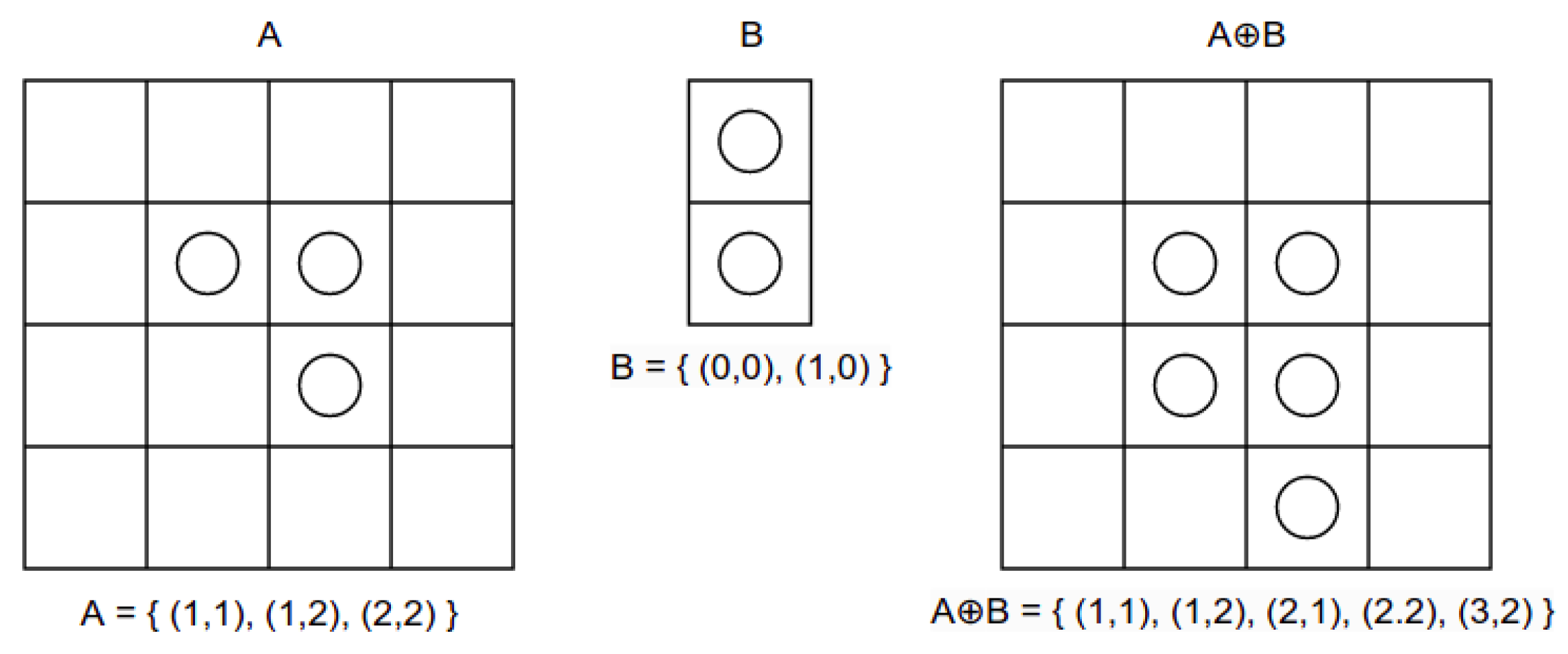
3.2. Morphological Transformations

Morphological transformations are derived from Mathematical Morphology, which offers a mathematical approach to processing digital images based on shape. The shape of an object can be represented as the group composed of all the white pixels in a binary image. Because an image exists in Euclidean 2-space ( E 2 ), this group of pixels can be denoted as a Euclidean 2-space set with elements representing the coordinates of the white pixels that define the object’s shape (row_index and column_index). In this context, the morphological transformations are functions applied to these sets of pixels.

3.2.1. Dilation

The dilation (Figure 1) between the subsets A and B of E 2 is defined as:
A B = { c E 2 | c = a + b a A a n d b B }
In practice, the first operand A is considered the image undergoing the analysis, while the second operand B is considered the structuring element (also known as the kernel), which is responsible for the different types of dilation transformation.

3.2.2. Erosion

The erosion (Figure 2) is the morphological dual of the dilation because it combines two sets by using vector subtraction. The erosion of A by B is the set of all elements x for which x + b ∈ A for every b:
A B = { x E 2 | x + b A b B }
In practice, the morphological transformations are executed through a sort of convolution operation. In particular, assuming that the kernel B has an anchor point that corresponds to the center of the kernel, then there is the following:
Dilation: As the kernel B is scanned over the image A, the pixel value of the image A under the anchor point of the kernel B is replaced with the maximum pixel value overlapped by B in the original input image A:
OutImg ( x , y ) = max ( x , y ) : k e r n e l ( x , y ) 0 InImg ( x + x , y + y )
Depending on the type of kernel used, this maximizing operation causes bright regions within the image to spread in different ways across the neighbor pixels.
Erosion: As the kernel B is scanned over the image, the pixel value of the image A under the anchor point of the kernel B is replaced with the minimum pixel value overlapped by B in the original input image A:
OutImg ( x , y ) = min ( x , y ) : k e r n e l ( x , y ) 0 InImg ( x + x , y + y )
Depending on the type of kernel used, this minimizing operation leads to bright areas of the image getting thinner, whereas the dark zones are getting larger.

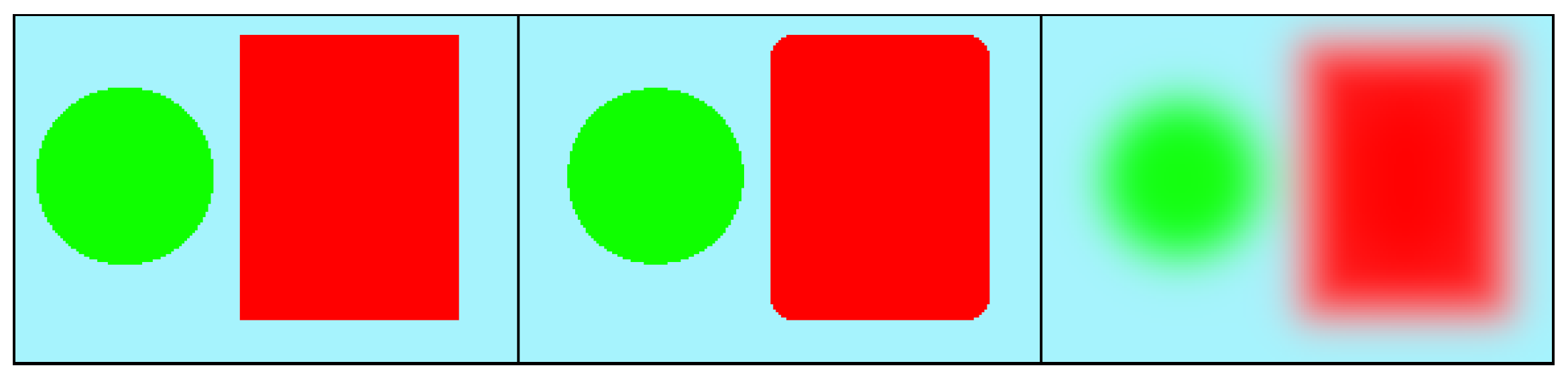
3.3. Median Blur Filter

The median blur is a simple kernel filter that slides over the input image; instead of computing the mean of the pixels overlapped by it, as the Gaussian blur filter does, it calculates the median value, which represents the middle value among the overlapped pixels (Figure 3). In general, this filter is used to preserve edges and rounded corners while reducing noise.

4. Methodology

4.1. Software Overview

The proposed system is divided into 4 main phases: Pre-Calibration (for correctly positioning the user in the field of view of the camera), Calibration (for understanding when the user is looking at the screen), Active Tracking (for tracking the eyes’ trajectory), and Data Saving (for generating a JSON file containing the data collected).

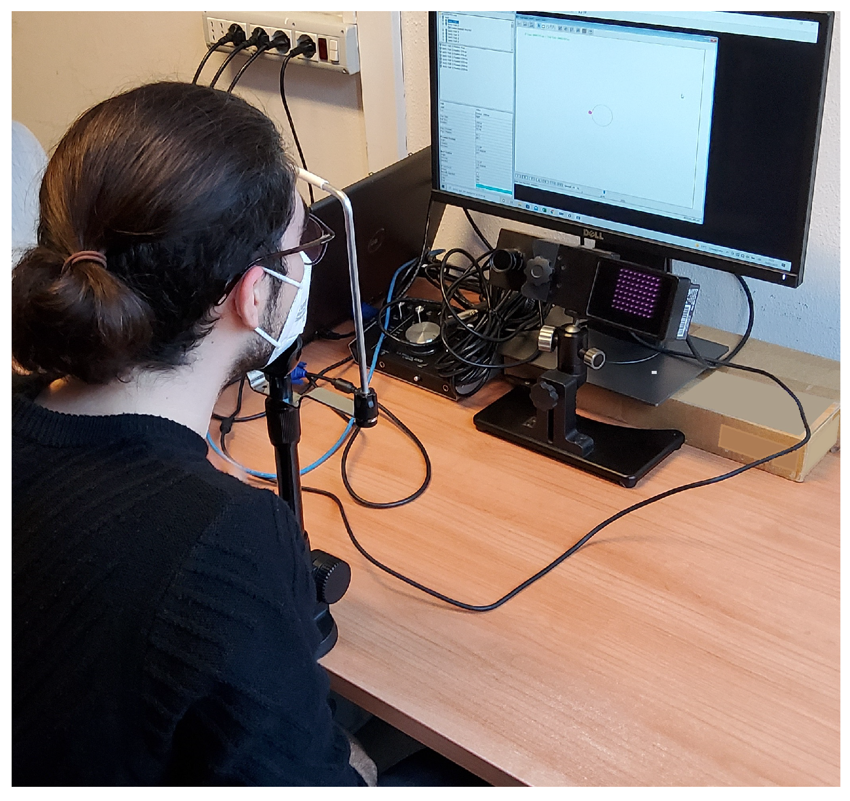
4.1.1. Pre-Calibration

The main task for users during this mandatory phase is to center themselves in the camera’s frame and align their facial orientation with the camera’s frame by adjusting the displayed angles to zero, which represents the orientation of the face reference frame with respect to the camera reference frame. The face’s orientation is calculated considering the angles of displacement between the unit vectors of these two reference frames. In detail, the camera reference frame is oriented as the x and y axes of the image coordinate space and the z axis is pointing inside the frame. The face reference frame is calculated by using some of the 3D facial landmarks produced by the Face Mesh function. Specifically, the landmarks representing the inner corners of the eyes determine the x axis, the landmarks indicating the upper and lower bounds of the head establish the y axis, and the z axis is the cross product between the x and y axes.

4.1.2. Calibration

In this phase, a 9-point calibration is employed to associate the eyes’ positions with the screen’s positions. In particular, the eye position associated with the central point of the screen is utilized as a reference point during the Active Tracking phase to mimic the distance vector utilized in the corneal-reflection-based methods. To effectively detect the eyes’ positions, a computer vision pipeline (shown in Figure 4) composed of widely recognized image processing functions is utilized.

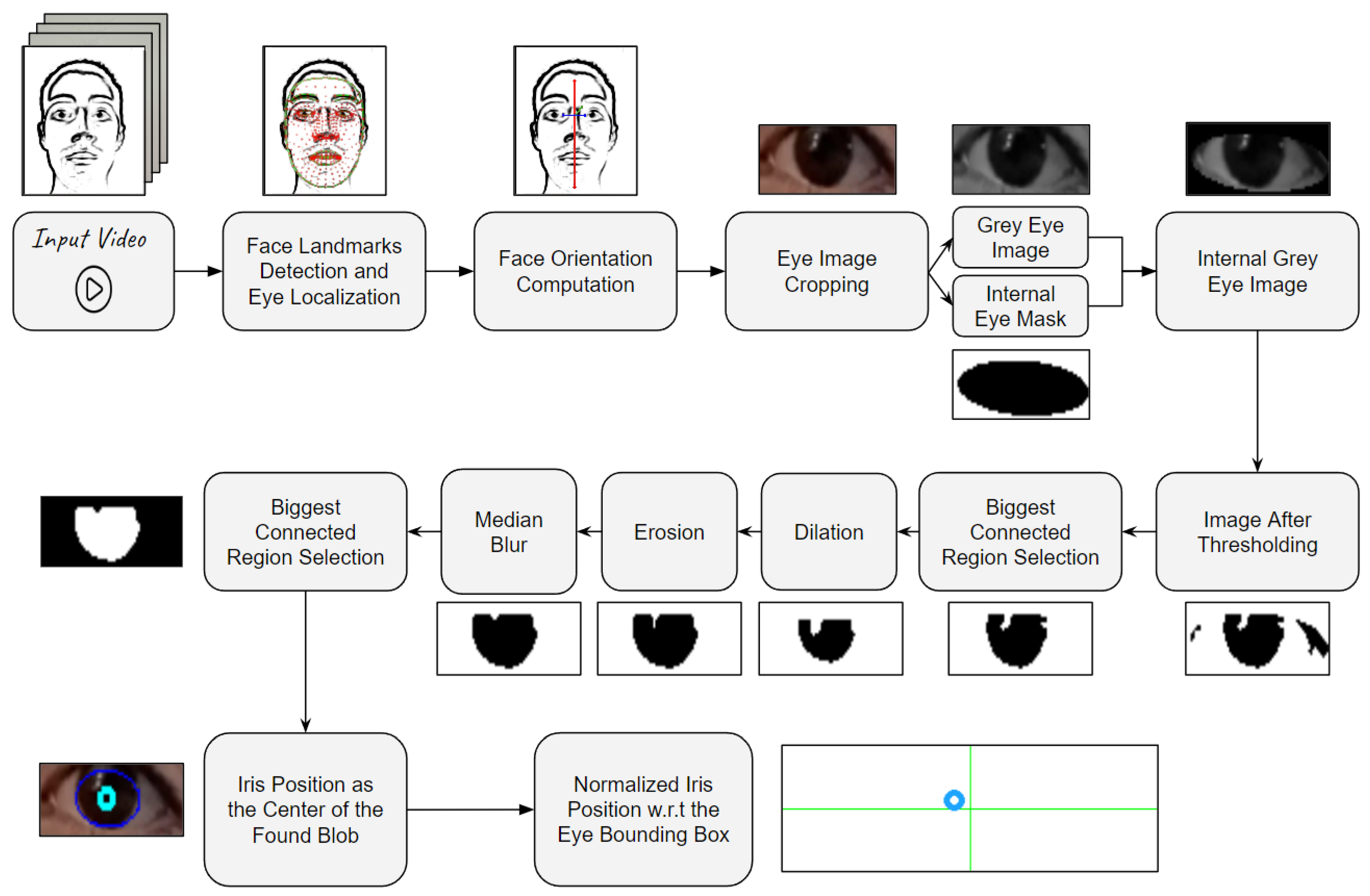
4.1.3. Irises Detection Algorithm (IDA)

In detail, this pipeline begins by detecting facial landmarks using the Face Mesh function in the current analyzed frame. If these landmarks are successfully identified, they can be utilized to calculate the face orientation with respect to the camera reference frame, which is then employed to determine whether the user is looking at the screen. Under normal conditions, if any of the angles representing the face orientation are in modulo less than 30 degrees, then it can be concluded that the user is looking at the screen. In situations where the facial landmarks are not detected, the user’s face is not entirely within the camera’s frame, or it is determined that the user is not looking at the screen, the currently analyzed frame is skipped. When the user is confirmed to be looking at the screen, the landmarks delineating the contours of the eyes are used for three purposes: cropping the eye regions from the image, calculating the orientation of each eye in relation to the x axis of the image, and generating one elliptical mask for each cropped eye image. The segmented eye regions are created by employing the bounding boxes of the eye landmarks and are then converted to grayscale. This conversion helps normalize the color information and ensures a more consistent representation of the eyes for further processing. The orientation of the eyes is crucial to account for users who may be looking at the screen with their head slightly tilted. For that reason, later in the pipeline, the detected 2D positions of the irises are rotated, ensuring that all trajectory points are computed with a consistent orientation. The elliptical masks precisely delineate the internal components of the eye (including the sclera, iris, and pupil) and are employed to remove extraneous skin pixels from the grayscale eye images. After applying these masks, an adaptive threshold is generated and used to identify the iris and pupil pixels. This threshold value, ranging from 0 to 255, represents the pixel intensity value so that 30% of the darkest pixels within the internal part of the eye area are kept after thresholding the image. This percentage comes from several experiments that we have conducted with various light conditions and people with different skin and iris colors. This thresholding process may result in multiple connected regions in the image, which can be caused by factors such as eyelashes, makeup, or light reflections in the iris. To address this issue, only the largest connected region is selected to form the iris blob. To refine it, the following sequence of image processing functions is applied: dilation, erosion, and median blur. In detail, the dilation is performed using a vertical kernel to remove possible pixels representing eyelashes or the internal contour of the eye. The erosion is carried out using a circular kernel to enhance the shape of the iris, and the median blur is employed to smooth the blob. Once again, different connected regions can be generated through the application of these three filters, and only the largest one is selected to continue the process. In the final stage, a fitting algorithm is used to find the minimal ellipse that encloses the chosen iris blob. The center of this minimal ellipse represents the detected 2D position of the iris in the original eye image. This 2D position is then rotated using the angle calculated a few steps earlier in order to align the major and minor axes of the computed ellipse with the x and y axes of the camera’s reference frame. This rotation ensures that all trajectory points are computed with a consistent orientation. Additionally, the position of the iris is normalized with respect to the size of the original eye image rather than being computed in image coordinates.

4.1.4. Active Tracking and Data Saving

After the calibration, the user can start executing the task, and for each frame captured by the camera, the Irises Detection Algorithm is used to detect the position of the eyes. Once the task has been completed, the acquired data are stored in a JSON file with the following structure: The first row contains the information acquired during the Calibration phase, which is the average positions with standard deviations of the left and right eye and the average user’s face orientation while looking at the calibration points. After the first one, each row of the JSON file represents the data extracted from a frame captured during the Active Tracking phase and contains the timestep at which the frame has been captured; the orientation of the face in the current frame; a value called inconsistency that represents the reliability of the data calculated for this frame and computed as the Euclidean distance between the face’s orientation during the Calibration phase and the one in the current analyzed frame; the position of the eyes (left and right) in percentage to the corresponding eye image shape; a distance vector from the position computed during the Calibration phase in which the user was looking at the screen’s center; and the distance from the position detected in the previous frame.

4.2. Participant Demographics in the Dataset

To validate our system, we conducted an experiment involving 60 participants. They spanned an age range from 18 to 40, with a mean average of 23.68 years. Specifically, it was 23.57 for females and 27.8 for males. The gender distribution was balanced, with 50% females and 50% males. The majority of participants (65%) had corrected vision, either through glasses or contact lenses, while the remaining 35% had uncorrected vision. The eye color percentages were distributed as follows: brown eyes (80%), blue eyes (15%), and other colors (5%). In terms of technology familiarity, 80% of the participants reported high levels of experience with digital devices. The remaining 20% had limited exposure to such technology. Regarding educational backgrounds, there was variation; approximately 70% of the participants had completed at least a bachelor’s degree, while the others held high school diplomas or advanced degrees.

5. Results

To test the capabilities of our application in distinguishing between saccades and fixations during eye movements, we decided to compare the trajectories obtained by our system to that of the EyeLink 1000 Plus in a simple saccadic task composed of 60 trials. At the beginning of each trial, the user had to look at the center of the screen for about 1.5 s. After this time interval, a red target appeared in a random position at, more or less, the same height as the screen’s center and stayed for 1.5 s. During this time period, the user was required to maintain focus on the target. Subsequently, once it disappeared, the user had to look back at the center of the screen, awaiting the beginning of the next trial. This specific experiment structure was employed to test the precision and accuracy of the developed system in recognizing saccades and fixations that are limited in a horizontal section of the screen. The setup used for this experiment (Figure 5) included a monitor screen positioned approximately 50 cm from the user’s face; the EyeLink 1000 Plus positioned below and in front of the monitor; a chin support to stabilize the head (required by the professional eye tracker); an RGB camera (with video resolution 2560 × 1140 ), which is positioned as close as possible to the EyeLink’s camera in order to provide the same view to both the eye trackers; and a laptop, on which the IDA was running, equipped with Ubuntu 16.04 as the Operative System, Intel(R) i7-4510U (2 GHz) as the CPU, and 4 GB RAM. In this analysis, our system demonstrated its robust capability to adapt to diverse scenarios. For instance, it effectively identified the users’ eye focus even in cases where they wore glasses, including those with a blue light filter; applied makeup; and exhibited bright irises. At the conclusion of the test, all the x-axis trajectories recorded by both the eye trackers were normalized to a range of [−1, 1] (Figure 6). In particular, the value 0 represents the position in which the user was looking at the center of the screen, while −1 and 1 represent the positions in which the user was looking at the right and left borders of the screen. Before putting the obtained paths in relation to each other, it is necessary to notice that our system used an RGB camera with an average of 25 fps, while the EyeLink recorded at 500 fps. In order to have a general idea of the similarity between the obtained trajectories, the Dynamic Time Warping (DTW) algorithm was employed.

5.1. Dynamic Time Warping Algorithm

DTW is a similarity measure between time series that was extensively explored in the 1970s, especially in applications related to speech recognition [28,29,30]. By considering two time series t, t in the same n-dimensional space, with length l 1 and l 2 and elements t i and t j , the DTW searches for the optimal temporal alignment that minimizes the Euclidean distance between the aligned series. The temporal alignment is the matching between the time indexes of the two time series of the form π = [ ( i 0 , j 0 ) , . . . , ( i h , j h ) ] . The optimization process implemented by DTW can be formalized as follows:
D T W q ( t , t ) = min π Π ( t , t ) ( ( i , j ) π d ( t i , t j ) q ) 1 q
where Π ( t , t ) is the set of all admissible paths and d ( · ) is the difference between the data points t i and t j . In the original formulation of DTW, a path π is admissible if it satisfies the following conditions:
  • π 0 = ( 0 , 0 ) : the starting indices of both time series have to be matched together;
  • π h 1 = ( l 1 1 , l 2 1 ) : the ending indices of both time series have to be matched together;
  • i k 1 i k i k + 1 + 1 and j k 1 j k j k + 1 + 1 : the sequence of the indices of both time series have to be monotonically increasing and all the indices should appear at least once.
In addition to the minimal Euclidean distance obtained by DTW, a graphical representation of the similarity between the input time series can be generated by computing a binary matrix whose non-zero entries are those corresponding to the matching between the time series indices. Specifically, this binary matrix has dimensions l 1 × l 2 , where each element A i , j is equal to 1 if ( i , j ) π or otherwise 0. This structure helps in visualizing the aligned indices between the two series: the more the resulting curve represents a straight line from ( 0 , 0 ) to ( l 1 , l 2 ) and the more the similarity between the time series analyzed is high.
As shown in Figure 7, the DTW algorithm clearly revealed that the shape of the two trajectories matched very well. Moreover, by relying on the time stamps, a manual comparison can be conducted by selecting for each data point generated from our system the corresponding one generated by the EyeLink. From this comparison, it can be observed that our system achieves a lower absolute accuracy compared to the EyeLink, which relies on an IR camera and a chin stabilizer to restrict user movement throughout the entire task. This difference is highlighted in the bottom-left plot in Figure 8, where the data points tracked by our system deviate a bit from the ones produced by the professional tool. However, this obtained accuracy is not an issue when following the eye movements. In fact, having a high precision is good enough to distinguish between the different gaze directions. Despite our system dealing with higher noise resulting from the use of a simple RGB camera and allowing users to move freely during the task execution, it is still capable of achieving elevated precision, comparable to that of the EyeLink, when the gaze movements on the screen are executed along the x axis of the screen.

5.2. System Limitations

While the presented eye-tracking system demonstrates overall promising capabilities and precision, it is crucial to acknowledge the potential limitations associated with this technology. The system’s sensitivity to external factors, such as lighting conditions and reflections, occlusions (e.g., hair partially obstructing the eyes), extensive head movements, or errors in the initial calibration phase, can have a significant negative impact on the eye-tracking results. Even if our system works well in static applications, the performance in highly dynamic environments (such as unsupervised remotely executed tasks) could decrease a bit due to the reliance on facial landmarks and the need for a consistent orientation for accurate tracking. This implies that large head movements, such as substantial head rotations or tilts, may disrupt the system’s ability to maintain precise gaze tracking, emphasizing the need for users to maintain a relatively stable head position for optimal performance. However, it is worth emphasizing that these identified limitations were already taken into account during the development of the application and that the idea behind our system was not to achieve the highest possible accuracy but rather to provide an affordable and reliable tool compared to the existing market alternatives.

6. Conclusions

In this paper, we introduce an innovative real-time eye-tracking system that distinguishes itself on two fronts. Firstly, our approach stands out for its cost-effectiveness and accessibility, utilizing a single RGB camera (even when not in HD) instead of more precise yet expensive alternatives, such as IR cameras or wearable devices. Secondly, our Iris Detection Algorithm (IDA) features an original design. This algorithm integrates fast machine learning models for face landmark detection with computationally efficient computer vision techniques (e.g., morphological transformations, thresholding, histogram computation, blob detection, and a median blur filter) strategically employed to achieve precise iris pixel segmentation. Therefore, our unique contribution spans both the selection of economical hardware and the intricate design of the IDA. This combined innovation transforms real-time eye-tracking technology, making it more useful, inclusive, and affordable for a wider range of users.
The results of a quantitative comparison show that the developed system is effectively capable of distinguishing, in real time, saccades and fixations when the movements of the eyes are mainly horizontal as well as the EyeLink 1000 Plus. Hence, the proposed system could have great potential in various applications focusing on the attention mechanism, such as psychological tests, people’s safety while driving, and website design analysis.
Looking ahead, future improvements for our system can be directed toward enhancing the general accuracy of the detected 2D iris trajectory, particularly along the y axis of the screen. A fundamental step in achieving this enhancement is to refine the detection of the iris pixels within the eye regions. A possible solution entails employing a regression model to predict the adaptive threshold to utilize. An alternative solution is the use of a neural network to directly produce the 2D iris position within the eye image given as input. In particular, the implementation of these models could leverage CNNs or Visual Transformers (ViTs) that result in SOTA techniques for manipulating images.
The prevalent use of machine learning techniques is indeed a cornerstone in modern eye-tracking systems. Specifically, the focus of these new systems is shifting from achieving high accuracy to producing reliable, cost-effective, portable, and movement-independent solutions. This strategic shift aims to make these systems more commonplace and affordable tools across various fields of study, aligning with the core concept behind the development of our system.

Author Contributions

Conceptualization, S.R. and C.N.; methodology, E.I., V.P. and S.R.; software, E.I. and V.P.; validation, S.R.; formal analysis, C.N.; investigation, E.I., V.P. and S.R.; resources, S.R.; data curation, S.R.; writing—original draft preparation, E.I., V.P. and S.R.; writing—review and editing, S.R. and C.N.; supervision, C.N.; project administration, S.R.; funding acquisition, C.N. All authors have read and agreed to the published version of the manuscript.

Funding

This paper has been partially supported by the Age-It: Ageing Well in an ageing society project, task 9.4.1, work package 4, spoke 9, within topic 8, extended partnership 8, under the National Recovery and Resilience Plan (PNRR), Mission 4, Component 2, Investment 1.3—Call for tender No. 1557 of 11/10/2022 of the Italian Ministry of University and Research funded by the European Union—NextGenerationEU, CUP B53C22004090006.

Data Availability Statement

The data presented in this study are available on request from the corresponding author.

Acknowledgments

This work was developed at the is.Lab() Intelligent Systems Laboratory of the Department of Computer, Control, and Management Engineering, Sapienza University of Rome.

Conflicts of Interest

The authors declare no conflict of interest.

References

  1. Roper-Hall, G. Louis émile javal (1839–1907): The father of orthoptics. Am. Orthopt. J. 2007, 57, 131–136. [Google Scholar] [CrossRef] [PubMed]
  2. Armstrong, T.; Olatunji, B.O. Eye tracking of attention in the affective disorders: A meta-analytic review and synthesis. Clin. Psychol. Rev. 2012, 32, 704–723. [Google Scholar] [CrossRef] [PubMed]
  3. Pepe, S.; Tedeschi, S.; Brandizzi, N.; Russo, S.; Iocchi, L.; Napoli, C. Human Attention Assessment Using A Machine Learning Approach with GAN-based Data Augmentation Technique Trained Using a Custom Dataset. OBM Neurobiol. 2022, 6, 17. [Google Scholar] [CrossRef]
  4. Wedel, M.; Pieters, R. Eye tracking for visual marketing. Found. Trends Mark. 2008, 1, 231–320. [Google Scholar] [CrossRef]
  5. Lee, T.T.; Yeung, M.K.; Sze, S.L.; Chan, A.S. Eye tracking use in researching driver distraction: A scientometric and qualitative literature review approach. Brain Sci. 2021, 11, 314. [Google Scholar] [CrossRef] [PubMed]
  6. Danielson, M.L.; Bitsko, R.H.; Ghandour, R.M.; Holbrook, J.R.; Kogan, M.D.; Blumberg, S.J. Prevalence of Parent-Reported ADHD Diagnosis and Associated Treatment Among U.S. Children and Adolescents, 2016. J. Clin. Child Adolesc. Psychol. 2018, 47, 199–212. [Google Scholar] [CrossRef] [PubMed]
  7. Ponzi, V.; Russo, S.; Wajda, A.; Napoli, C. A Comparative Study of Machine Learning Approaches for Autism Detection in Children from Imaging Data. In Proceedings of the CEUR Workshop Proceedings, Catania, Italy, 26–29 August 2022; Volume 3398, pp. 9–15. [Google Scholar]
  8. Țichindelean, M.; Țichindelean, M.T.; Orzan, I.C.G. A Comparative Eye Tracking Study of Usability—Towards Sustainable Web Design. Sustainability 2021, 13, 10415. [Google Scholar] [CrossRef]
  9. Cvahte, O.; Darja, T.; Darja, T. Eye tracking use in researching driver distraction: A scientometric and qualitative literature review approach. J. Eye Mov. Res. 2019, 12. [Google Scholar] [CrossRef]
  10. Zhang, X.; Sugano, Y.; Bulling, A. Evaluation of appearance-based methods and implications for gaze-based applications. In Proceedings of the 2019 CHI Conference on Human Factors in Computing Systems, Glasgow, UK, 4–9 May 2019; pp. 1–13. [Google Scholar]
  11. Ponzi, V.; Russo, S.; Bianco, V.; Napoli, C.; Wajda, A. Psychoeducative Social Robots for an Healthier Lifestyle using Artificial Intelligence: A Case-Study. In Proceedings of the CEUR Workshop Proceedings, Virtual, 20 August 2021; Volume 3118, pp. 26–33. [Google Scholar]
  12. De Magistris, G.; Caprari, R.; Castro, G.; Russo, S.; Iocchi, L.; Nardi, D.; Napoli, C. Vision-Based Holistic Scene Understanding for Context-Aware Human-Robot Interaction. In Proceedings of the 20th International Conference of the Italian Association for Artificial Intelligence, Virtual Event, 1–3 December 2021; Lecture Notes in Computer Science (Including Subseries Lecture Notes in Artificial Intelligence and Lecture Notes in Bioinformatics). Volume 13196, pp. 310–325. [Google Scholar] [CrossRef]
  13. Kim, B.C.; Ko, D.; Jang, U.; Han, H.; Lee, E.C. 3D Gaze tracking by combining eye- and facial-gaze vectors. J. Supercomput. 2017, 73, 3038–3052. [Google Scholar] [CrossRef]
  14. Xiong, X.; Liu, Z.; Cai, Q.; Zhang, Z. Eye gaze tracking using an RGBD camera: A comparison with a RGB solution. In Proceedings of the 2014 ACM International Joint Conference on Pervasive and Ubiquitous Computing: Adjunct Publication, Seattle, WA, USA, 13–17 September 2014; pp. 1113–1121. [Google Scholar]
  15. Wang, K.; Ji, Q. Real time eye gaze tracking with 3d deformable eye-face model. In Proceedings of the IEEE International Conference on Computer Vision, Venice, Italy, 22–29 October 2017; pp. 1003–1011. [Google Scholar] [CrossRef]
  16. Wang, C.; Shi, F.; Xia, S.; Chai, J. Realtime 3D eye gaze animation using a single RGB camera. ACM Trans. Graph. (TOG) 2016, 35, 1–14. [Google Scholar] [CrossRef]
  17. Wang, Z.; Chai, J.; Xia, S. Realtime and Accurate 3D Eye Gaze Capture with DCNN-Based Iris and Pupil Segmentation. IEEE Trans. Vis. Comput. Graph. 2021, 27, 190–203. [Google Scholar] [CrossRef] [PubMed]
  18. Ronneberger, O.; Fischer, P.; Brox, T. U-net: Convolutional networks for biomedical image segmentation. In Proceedings of the Medical Image Computing and Computer-Assisted Intervention–MICCAI 2015: 18th International Conference, Munich, Germany, 5–9 October 2015; Proceedings, Part III 18. Springer: Cham, Switzerland, 2015; pp. 234–241. [Google Scholar]
  19. Iandola, F.N.; Han, S.; Moskewicz, M.W.; Ashraf, K.; Dally, W.J.; Keutzer, K. SqueezeNet: AlexNet-level accuracy with 50x fewer parameters and <0.5 MB model size. arXiv 2016, arXiv:1602.07360. [Google Scholar]
  20. Albawi, S.; Mohammed, T.A.; Al-Zawi, S. Understanding of a convolutional neural network. In Proceedings of the 2017 International Conference on Engineering and Technology (ICET), Antalya, Turkey, 21–23 August 2017; IEEE: Piscataway, NJ, USA, 2017; pp. 1–6. [Google Scholar]
  21. Krafka, K.; Khosla, A.; Kellnhofer, P.; Kannan, H.; Bhandarkar, S.M.; Matusik, W.; Torralba, A. Eye Tracking for Everyone. In Proceedings of the IEEE Conference on Computer Vision and Pattern Recognition (CVPR), Las Vegas, NV, USA, 26 June–1 July 2016. [Google Scholar]
  22. Cottrell, S.S. A simple method for finding the scattering coefficients of quantum graphs. J. Math. Phys. 2015, 56, 092203. [Google Scholar] [CrossRef]
  23. Cheung, Y.m.; Peng, Q. Eye Gaze Tracking With a Web Camera in a Desktop Environment. IEEE Trans. Hum. Mach. Syst. 2015, 45, 419–430. [Google Scholar] [CrossRef]
  24. Meng, C.; Zhao, X. Webcam-Based Eye Movement Analysis Using CNN. IEEE Access 2017, 5, 19581–19587. [Google Scholar] [CrossRef]
  25. Tonsen, M.; Steil, J.; Sugano, Y.; Bulling, A. InvisibleEye: Mobile Eye Tracking Using Multiple Low-Resolution Cameras and Learning-Based Gaze Estimation. In Proceedings of the ACM on Interactive, Mobile, Wearable and Ubiquitous Technologies; Association for Computing Machinery: New York, NY, USA, 2017; Volume 1. [Google Scholar] [CrossRef]
  26. Liu, W.; Anguelov, D.; Erhan, D.; Szegedy, C.; Reed, S.; Fu, C.Y.; Berg, A.C. Ssd: Single shot multibox detector. In Proceedings of the Computer Vision–ECCV 2016: 14th European Conference, Amsterdam, The Netherlands, 11–14 October 2016; Proceedings, Part I 14. Springer: Cham, Switzerland, 2016; pp. 21–37. [Google Scholar]
  27. Sandler, M.; Howard, A.; Zhu, M.; Zhmoginov, A.; Chen, L.C. Mobilenetv2: Inverted residuals and linear bottlenecks. In Proceedings of the IEEE Conference on Computer Vision and Pattern Recognition, Salt Lake City, UT, USA, 18–22 June 2018; pp. 4510–4520. [Google Scholar]
  28. Sakoe, H.; Chiba, S. Dynamic programming algorithm optimization for spoken word recognition. IEEE Trans. Acoust. Speech Signal Process. 1978, 26, 43–49. [Google Scholar] [CrossRef]
  29. Vintsyuk, T.K. Speech discrimination by dynamic programming. Cybernetics 1968, 4, 52–57. [Google Scholar] [CrossRef]
  30. Myers, C.; Rabiner, L.; Rosenberg, A. Performance tradeoffs in dynamic time warping algorithms for isolated word recognition. IEEE Trans. Acoust. Speech Signal Process. 1980, 28, 623–635. [Google Scholar] [CrossRef]
Figure 1. Schematic representation of the application of a dilation transformation. Each matrix represents a binary image, where empty cells correspond to black pixels and cells with circles represent white pixels. To perform dilation, a binary image can be expressed as a set of index pairs indicating the positions of white pixels (e.g., (0,0) denotes the upper-left corner). According to Equation (1), the application of a dilation operation produces a new set by summing each element of the original image A with each element of the dilation operator B. For instance, applying dilation to the first element of A (e.g., (1,1)) yields two new elements in A ⊕ B: (1,1) (obtained through summation with the first element of B (0,0)) and (2,1) (obtained through summation with the second element of B (1,0)).
Information 14 00644 g001
Figure 2. Schematic representation of the application of an erosion transformation. Each matrix in this figure represents a binary image, where empty cells correspond to black pixels and cells with circles represent white pixels. To perform erosion, a binary image can be expressed as a set of index pairs indicating the positions of white pixels (e.g., (0,0) denotes the upper-left corner). An equivalent procedure to Equation (2) for applying erosion involves generating a new set that includes only those elements of the original image A such that, by sliding the erosion operator B over A, the operator B perfectly fits the shape of those elements of A.
Information 14 00644 g002
Figure 3. Example of how an image (left) is modified after the application of the median blur filter (center) and the Gaussian blur filter (right).
Information 14 00644 g003
Figure 4. The Iris Detection Algorithm pipeline begins by detecting facial landmarks using the Face Mesh function on an image captured by the webcam. It then computes the face’s orientation based on these landmarks and, if the user is looking at the screen, uses the eyes’ landmarks to crop the eye regions. Subsequently, each eye image is converted to grayscale, and a mask representing the internal part of the eye is applied. On the resulting image, an adaptive threshold is employed to identify the iris pixels, and only the largest connected region is kept. Following this step, in sequence, a dilation, an erosion, and a median blur filter are applied to refine the iris blob. Next, the largest connected region is selected, and the center of the minimal ellipse enclosing it represents the position of the iris in the eye image. Finally, the detected position is normalized according to the shape of the eye image.
Information 14 00644 g004
Figure 5. Setup of the experiment comparing the capabilities in detecting saccades and fixations between the EyeLink 1000 Plus and our developed system.
Information 14 00644 g005
Figure 6. This image shows the normalized trajectories obtained from the EyeLink 1000 Plus (top image) and from our developed system employing the IDA (bottom image).
Information 14 00644 g006
Figure 7. A visual representation of the DTW algorithm’s output applied to the trajectories obtained from the developed system (displayed on the x axis) and the EyeLink 1000 Plus (displayed on the y axis) shows a nearly linear similarity between them.
Information 14 00644 g007
Figure 8. The two top images represent the normalized trajectories obtained from the EyeLink 1000 Plus (left image) and from the developed system (right image) during the same time interval. The two images at the bottom show both these trajectories overlapped with a dot representation (left image) and a straight-line representation (right image).
Information 14 00644 g008
Disclaimer/Publisher’s Note: The statements, opinions and data contained in all publications are solely those of the individual author(s) and contributor(s) and not of MDPI and/or the editor(s). MDPI and/or the editor(s) disclaim responsibility for any injury to people or property resulting from any ideas, methods, instructions or products referred to in the content.

