Article

Secure and Fast Image Encryption Algorithm Based on Modified Logistic Map

1
Department of Electronics, Quaid-i-Azam University, Islamabad 45320, Pakistan
2
Department of Electrical Engineering, National University of Modern Languages, Islamabad 44000, Pakistan
3
Department of Technology, The University of Lahore, Lahore 54000, Pakistan
4
Department of Environmental & IT Engineering, Chungnam National University, Daejeon 34134, Republic of Korea
5
Electrical Engineering Department, College of Engineering, FEU Institute of Technology, Manila 1015, Philippines
6
Department of Computer Science, University of Cyprus & CYENS Centre of Excellence, Nicosia 20537, Cyprus
*
Authors to whom correspondence should be addressed.
These authors contributed equally to this work.
Information 2024, 15(3), 172; https://doi.org/10.3390/info15030172
Submission received: 6 February 2024 / Revised: 18 March 2024 / Accepted: 18 March 2024 / Published: 21 March 2024

Abstract

:
In the past few decades, the transmission of data over an unsecure channel has resulted in an increased rate of hacking. The requirement to make multimedia data more secure is increasing day by day. Numerous algorithms have been developed to improve efficiency and robustness in the encryption process. In this article, a novel and secure image encryption algorithm is presented. It is based on a modified chaotic logistic map (CLM) that provides the advantage of taking less computational time to encrypt an input image. The encryption algorithm is based on Shannon’s idea of using a substitution–permutation and one-time pad network to achieve ideal secrecy. The CLM is used for substitution and permutation to improve randomness and increase dependency on the encryption key. Various statistical tests are conducted, such as keyspace analysis, complexity analysis, sensitivity analysis, strict avalanche criteria (SAC), histogram analysis, entropy analysis, mean of absolute deviation (MAD) analysis, correlation analysis, contrast analysis and homogeneity, to give a comparative analysis of the proposed algorithm and verify its security. As a result of various statistical tests, it is evident that the proposed algorithm is more efficient and robust as compared to previous ones.

1. Introduction

In recent years, the multimedia and communications industry has been developing at a rapid pace. Many large streams of multimedia data are transmitted over an unsecure channel. As the rate of hacking has increased with the passage of time, the security of the data must be increased rapidly [1]. Numerous algorithms have been developed that are efficient and robust, but are still not sufficient to protect data to a desired level. In addition, less computationally complex algorithms are required to cater to the need to secure high-speed data transmissions. A lossless, novel and secure image encryption algorithm based on the modified chaotic logistic map (CLM) that takes less computational time for encryption is presented in this article. The results presented in this article demonstrate the following contributions, as depicted by the proposed image encryption algorithm.
  • The proposed image encryption method gives a less computationally complex arrangement of the encryption/decryption process, making it lightweight without compromising on the security of the algorithm.
  • The key used in the algorithm is the population growth of the modified chaotic logistic map. The keyspace is enhanced in comparison with the original chaotic logistic map.
  • One-time substitution is performed in the proposed algorithm, which provides good SAC as compared to classical techniques.
  • Various statistical and visual tests prove its resistance to linear and differential attacks.
According to Shannon [2], an ideal secrecy can be achieved if and only if an encryption method essentially contains substitution and permutation processes. After thorough testing, we discover that the histogram is not evenly distributed using only one-time substitution and permutation. Therefore, a stream of pseudorandom numbers from the CLM is XORed to achieve the required result.

1.1. Motivation

In order to facilitate the requirements and security of high-speed data transmissions, an image encryption algorithm is required, which is
  • Less computationally complex;
  • Low-cost;
  • Time-efficient;
  • Provides lossless encryption.

1.2. Related Work

1.2.1. Importance of CLM

The CLM has many great features, such as sensitive dependence on initial conditions, random orbit, pseudorandomness, good ergodicity, better cross-correlation properties, high efficiency, better mixing properties and a large keyspace. These features also makes the CLM a potential candidate in quantum image encryption algorithms and is therefore quantum-safe [3,4,5]. The CLM also has a low computational cost, requires simpler hardware and is easy to implement [6]. It is verified that the CLM is capable of providing high-speed image encryption at a low cost [7].
A good encryption scheme must have a substitution–permutation (SP) network as indicated by C. E. Shanon [2] to increase the security [8]. Pixel-level substitution and permutation are used in the algorithm to save computation time and cost. Otherwise, if bit-level substitution and permutation are used, then the algorithm’s computation time and cost increase eight times.

1.2.2. Image Encryption Techniques Based on Permutation

Permutation is the property used for the rearrangement of pixels in some pseudorandom order. It means that several pixels of the encrypted image are affected by just changing one pixel of the original image. Therefore, it hides any dependency between the input image and the encrypted image [9]. An algorithm becomes more resistant to frequency analysis attacks by using permutation techniques. The permutation techniques are further classified into two categories: one is pixel-level permutation and the second is bit-level permutation. These permutations are achieved by employing various transforms [10,11], chaotic maps [12,13,14,15,16,17], cyclic shifts [18,19,20,21], hash functions [22], sorting techniques [15,23,24,25,26,27] and parallel computing [28]. Although, these transformational-technique-based algorithms have many flaws, one of them is that they create high security but increase time complexity, which further results in lengthy preprocessing and poor permutation performance. On the other hand, sorting-based permutation techniques give the best permutation effect, but the time complexity increases and memory cost becomes high. If cyclic shift permutation techniques are utilized, they reduce the computational complexity and reduce memory costs but weaken the permutation effect. There is a need for a secure encryption algorithm, which reduces the time complexity and memory cost, though not at the cost of a reduction in the security.

1.2.3. Image Encryption Techniques Based on Substitution

Substitution is used to obscure the connection between the corresponding pixels of the input image and the encrypted image. This property of substitution makes it ideal to hide the connection between the secret key and the encrypted image. Substitution is also subdivided into pixel-level substitution [10,11,12,13,14,15,16,17,24,25,26,27,29,30,31,32] and bit-level substitution [18,23,33,34]. In bit-level substitution, the substitution can be lengthy and thus time consuming. Therefore, in the proposed algorithm, pixel-level substitution is used.
Anees et al. [35] proposed a technique that implements three S-boxes for the substitution. However, it is proved that this technique is better than the classical techniques and lacks permutation capabilities. Arif et al. [36] proposed an encryption-technique-based chaotic logistic map, employing a hashing algorithm and AES S-boxes. Various statistical tests are performed and it is shown that their encryption technique is lightweight and efficient. Alawida [c] [37] proposed a technique for image encryption, which is based on permutation and double substitution. It is proved in this study that permutation and substitution alone cannot uniformly distribute the information of the input image in the encrypted image.

1.2.4. Image Encryption Techniques Based on Transformations

Image encryption can be lossy or lossless [38]. Various transformation techniques that are used for image encryption are lossy [10,11]. In the proposed algorithm, we employ a CLM because of its high dependency on initial conditions. A novel and secure image encryption algorithm based on a CLM that requires less computational time to encrypt an original image is presented. Shannon’s idea of using a substitution–permutation and one-time pad network to achieve ideal secrecy is the backbone of this research [2].

1.3. Objectives of the Research

An image encryption technique is presented, which is lossless, takes less time to encrypt/decrypt, has a low cost and is less computationally complex. The presented image encryption technique has achieved all of the above attributes, which is quantitatively proved under the results in Section 4.

1.4. Organization of the Paper

The rest of the paper is organized as follows: The proposed image encryption algorithm is presented in Section 2. The proposed algorithm’s pseudocode is given in Section 3. The results along with statistical tests are presented in Section 4. The conclusion of the research is presented in Section 5.

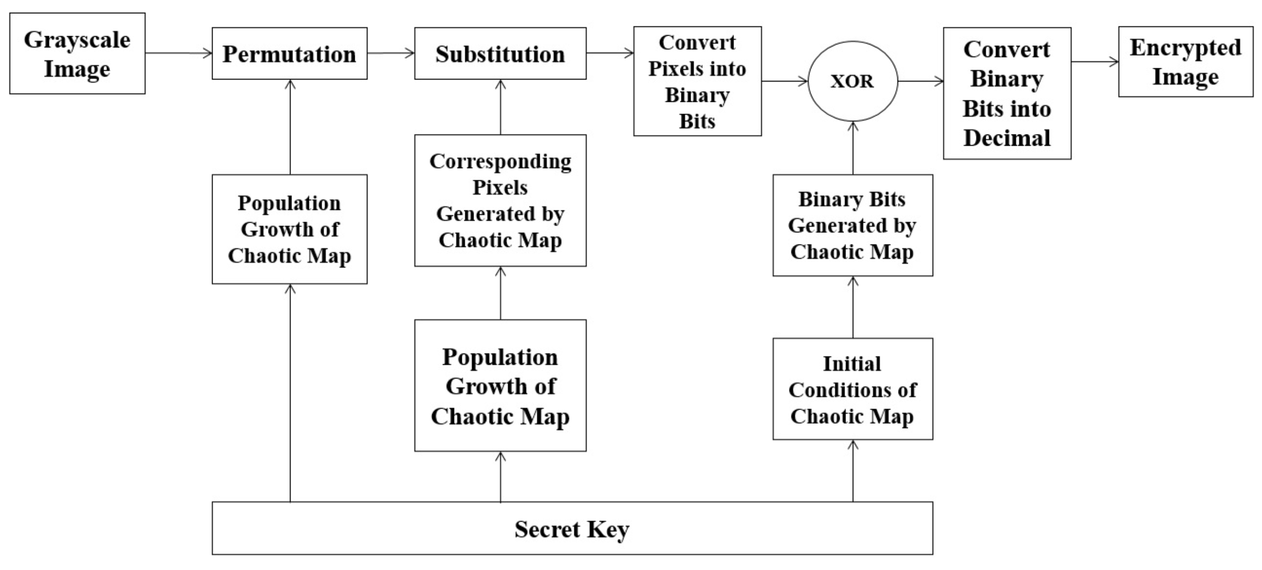
2. Proposed Algorithm

The encryption process is divided into six stages. A block diagram is given in Figure 1. In the first stage, the permutations on the grayscale image are performed. The second stage involves the substitution of pixel intensities of the permuted grayscale image. The pixel intensities are then converted into binary bits in the third stage. In the fourth stage, the random binary bits are collected from the CLM. In the fifth stage, the binary bits from stage three and four are added using an “XOR” operation. In the last and final stage, the resultant bits are converted into pixel intensities. The flowchart of the encryption process is given in Figure 2. The details of the six stages are presented as follows:

2.1. Permutation

The permutation process rearranges pixel intensities according to a sequence acquired from the CLM. For example, if a permutation matrix [2, 4, 1, 3] obtained from a CLM with population growth is applied to numbers 2 , 4 , 1 , 3 (pixel intensities), the resultant sequence after permutation is 4 , 3 , 2 , 1 . In an image, all the input pixels are shuffled in a random manner. In the proposed algorithm, the new rows and columns of the substituted image are computed by using the CLM, and the population growth is a part of its key.

2.1.1. Chaotic Logistic Map

The logistic map was first applied by Lorenz [39]. The governing equation for the logistic map is as follows:
b n + 1 = γ b n ( 1 b n )
where γ is the population growth of the logistic map. For the logistic map to be chaotic, its population growth must lie between 3.6 and 4. The proposed algorithm requires a unique combination of 256 numbers. Therefore, through extensive testing, it is determined that the numbers from [0, 255] arranged in ascending order are permuted with the help of the CLM. In order to obtain a unique combination, it is necessary for the population growth of the logistic map to be equal to 0.5, 1.5, 2.5, 3.5, 4.5, …. Only on these values can we achieve a unique and random combination of numbers in the range [0, 255]. Therefore, the equation is modified and can be rewritten as follows:
y = ( γ + 0.5 ) x ( 1 x ) w h e r e 0 x 255
where γ Z + is a set of positive integers. Equation (1) is used for the addition of pseudorandom bits in the substituted and permuted image. Equation (2) is used solely for the purpose of substitution and permutation. The bifurcation diagram of Equation (2) is given by Figure 3.

2.2. Behavior of the Modified CLM

The modified equation presented in this research enhances the security of the CLM and reduces the computational cost. In the proposed algorithm, a unique combination of 256 pixels is needed in order to carry out the substitution. Therefore, Equation (2) is used to obtain as many samples as needed. Through extensive testing, it is found that it has 256! distinct combinations. This modified CLM is then again utilized in permutation, which is explained in the current section. At this point, it has ( 256 × 256 ) ! distinct combinations. In Section 2.5, a simple CLM is used. The keyspace provided by the CLM is more than 2 302 [40]. All of these cascaded CLMs provide a huge keyspace while maintaining a low computational cost, which is the major achievement of this research.
We permute the arrangement of rows and columns. Consider an image of Lena ( 256 × 256 ). (The image and histogram are shown in Figure 4). Its permuted image and its histogram are shown in Figure 5. It is evident from both histograms (which are identical) that pixels are shuffled in such a manner that the permuted image is not depicting any resemblance with the original image.

2.3. Substitution

Substitution is a process in encryption where the bits from the original message are substituted with pseudorandom bits. It is used to obscure the relationship between the pixels of the input image and the corresponding pixels of the encrypted image [9]. Pixel intensities are used rather than bits to reduce computation time. Therefore, pixel intensities are substituted using enhanced version of the CLM, which is explained in Section 2.1.1.
An example of this substitution is shown in Table 1 and Table 2.
The substituted pixels are shown in Table 2, with a population growth at 5.5 of CLM.
In comparison to Table 1 and Table 2, pixel intensity 1 is substituted into pixel intensity 245. The permuted image of Lena is shown in Figure 5 and is substituted, and its image and histogram are shown in Figure 6. The histogram is not similar to uniform distribution; therefore, binary bits are added in the form of a one-time pad, which is explained in the latter sections.

2.4. Binary Form of the Image

The data of pixel intensities are now converted as a sequence of binary bits of 8-tuples. The range of pixel intensities is from 0 to 255. The pixel intensities from Section 2.3 (each pixel intensity is between 0 and 255) are now converted as a sequence of binary bits of 8-tuples. In the latter section, it will be easier for us to add random binary bits in the pixel intensities to increase the randomness and consequently increase the security of our proposed crypto system.

2.5. Bit Generation

It is a common misconception that a one-time pad is breakable. The opposite is true. If the key used in a one-time pad is random and is kept hidden from all possible hacks (attacks), then the only possible way to hack a one-time pad is by a brute force algorithm [41].
In this attack, all possible combinations are applied. For example, if the key consists of two bits, then there are 2 2 = 4 possible combinations. This means that, for a two-bit key, the hacker must enter the key four times. One of them is the actual key. In this way, a brute force attack can occur. In general, if the key is n bits long, then there will be 2 n combinations. C. E. Shannon [2] in his paper proves that ideal secrecy depends on the randomness of the key.
It is evident from the graph in Figure 7 that, if we increase the number of bits, then the number of combinations will also increase exponentially. Therefore, the hacker must have to enter more and more combinations if the key gets longer. The pseudorandom orbit of a chaotic logistic map is very high. The secret keyspace that a chaotic logistic map can offer is more than 2 302 [40]. The random binary bits are generated from the CLM.

2.6. XOR Operation

The binary of the pixel intensities and binary bits from the CLM are added in the form of an “XOR” operation. In the “XOR” operation, the same bits result in the output 0 and bits that are not the same give the output 1.

2.7. Conversion of Binary Bits to Encrypted Image

The resultant binary bits are then converted into pixel intensities. The acquired pixel intensities represent the encrypted image of Lena from the proposed algorithm. As an example, the substituted image of Lena shown in Figure 6 is then XORed. The encrypted image and its histogram are shown in Figure 8. The histogram resembles uniform distribution, as shown in Figure 8.

3. Pseudocode

The flowchart of the encryption process is given in Figure 2. The decryption process flowchart is given in Figure 9. The pseudocode for the encryption and decryption process is as follows:

3.1. Encryption

  • Input image is substituted using modified CLM.
  • Substituted image is then permuted using modified CLM.
  • Substituted pixels are then converted into binary bits.
  • Pseudorandom bits are evaluated from CLM.
  • Binary bits from 3. and 4. are XORed together.
  • Resultant bits are converted into pixels; therefore, an encrypted image is obtained.

3.2. Decryption

  • Encrypted image is converted into binary bits.
  • Pseudorandom bits are evaluated from CLM.
  • Binary bits from 1. and 2. are XORed together.
  • Binary bits are converted into pixels.
  • Reverse operation of substitution is applied.
  • Reverse operation of permutation is applied; therefore, an input image is obtained.

4. Results

We perform numerous statistical tests on the proposed encryption algorithm. These statistical tests include keyspace analysis, sensitivity analysis, strict avalanche criteria (SAC), histogram analysis, entropy analysis, mean of absolute deviation (MAD) analysis, correlation analysis, contrast analysis and homogeneity. The images used in the testing are taken from the University of Southern California-Signal and Image Processing Institute (USC—SIPI) database [42].

4.1. Computational Analysis

Computational complexity plays a key role in defining the cost and time of the encryption algorithm. Therefore, two main analyses are used. Keyspace analysis is used to check the proposed algorithm’s security against a brute force attack. Complexity analysis is used to check how much memory and time is utilized for the encryption process.

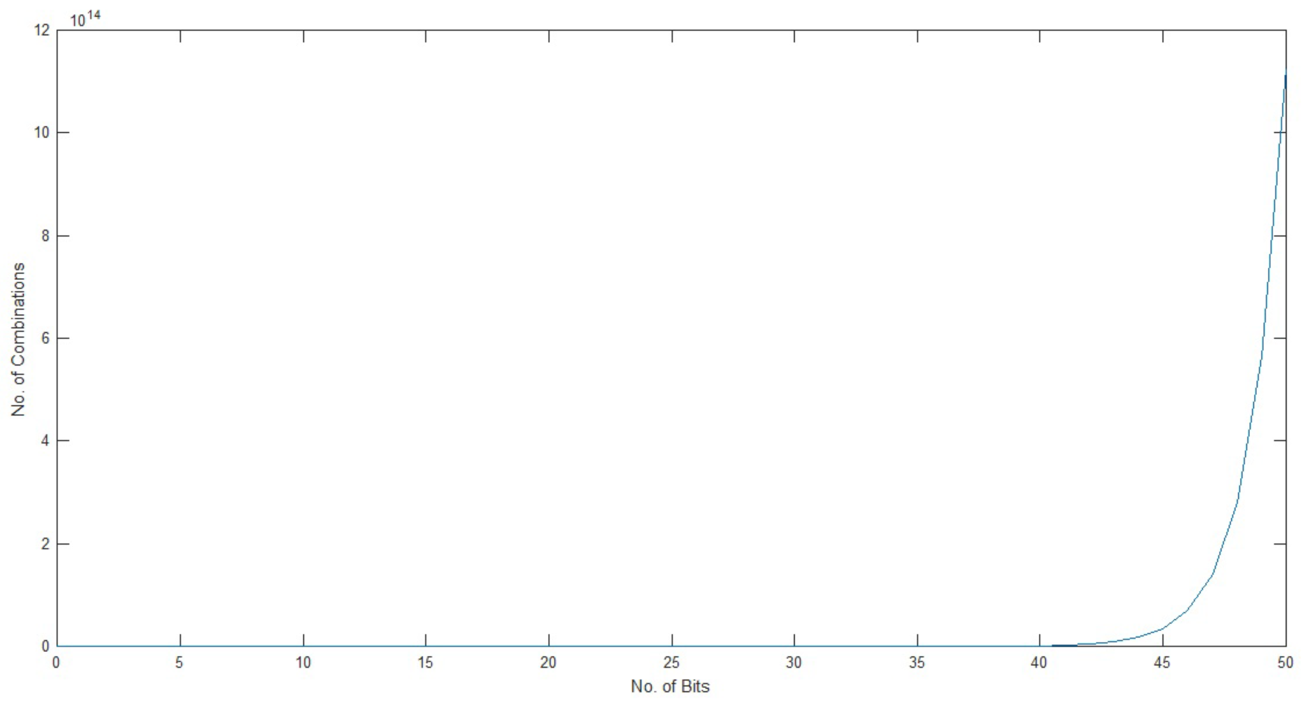
4.1.1. Keyspace Analysis

It is a well-known fact that a large keyspace is essential for an encryption algorithm to be resistant against a brute force attack [43]. The proposed algorithm uses the key at four different stages. First, the key is broken into four parts. The first two parts are used for permutation of the image. It has ( 256 × 256 ) ! distinct combinations. The third part is used in the S-box for substitution. It has 256 ! distinct combinations. The fourth part is used in obtaining the pseudorandom bits from the CLM. It ranges from [ 3.6 , 4 ] . Therefore, it accumulates a huge keyspace, and, as a result, increases the security of the encryption scheme.

4.1.2. Complexity Analysis

Complexity analysis is used to check how much memory and time is used to run a certain algorithm on a machine.
The permutation performance of the proposed algorithm is compared with some of the classical encryption algorithms as shown in Table 3. The proposed algorithm shows the best performance.

4.2. Sensitivity Analysis

The initial conditions of any algorithm play a key role in its security. Therefore, the security of the algorithm is dependent on its initial conditions. For this, two common measures are used [44,45], i.e., the number of pixels change rate (NoPCR) and unified average pixel changing intensity (UAPCI). This will make the encryption algorithm resistant against differential attacks. Strict avalanche criteria (SAC) are also used to verify the algorithm’s sensitivity.

4.2.1. Number of Pixels Change Rate (NoPCR)

This is used to check how a minute change in the input image can affect the output image. For this purpose, an input image is acquired, and only a one-bit change is performed in it. In image processing, a one-bit change means one intensity change in pixel value. The original input image and the one-bit-changed image are processed through the algorithm, and two separate ciphered images are acquired. After that, the following relationship is applied to both of the images.
D ( x , y ) = 0 , if C x , y 1 = C x , y 2 1 , if C x , y 1 C x , y 2
N o P C R = x , y D ( x , y ) B × H × 100 %
where
  • C 1 = cipher image of input image;
  • C 2 = cipher image of input image with one-bit change;
  • D ( x , y ) = matrix used to calculate difference between C 1 and C 2 ;
  • B = breadth of the image;
  • H = height of the image.
  • x and y represent the positions of the pixel in the horizontal and vertical direction, respectively.
In this manner, a percentage is computed to check how many pixels are changed in both of the ciphered images, i.e., between C 1 and C 2 . In this way, we are checking the security of our proposed algorithm. This is applied on various images, and some of the results are given in Table 4.
In Table 4, it is evident that a one-bit change in the input image can result in a more than 99% change in the ciphered image.

4.2.2. Unified Average Pixel Changing Intensity (UAPCI)

In the previous subsection, the change in number of pixels is calculated for the entire image. In this subsection, we compute how much one pixel is changed according to its neighboring pixel. A unified average value is computed for the whole image. First, two ciphered images are taken, whose input image is changed in one bit.
U A P C I = 1 B × H x , y | C x , y 1 C x , y 2 | 255 × 100 %
where
  • C 1 = cipher image of input image;
  • C 2 = cipher image of input image with one-bit change;
  • B = breadth of the image;
  • H = height of the image.
  • x and y represent the positions of the pixel in the horizontal and vertical direction, respectively.
In Table 5, the UAPCI of various images with different image sizes along with a one-bit change in the input image is given. It is proved from this table that an average of 7% change occurs from pixel to pixel if there is a one-bit change in the input image. These two measures show that the proposed algorithm is dependent on the input image. If any hacker tries to change the one-bit value in the system, it can easily be identified.

4.2.3. Strict Avalanche Criteria (SAC)

These are applied to check the algorithm’s dependency on its initial conditions in such a manner that one bit in “ O ” creates more than a 50% change in “ C ”. A function g : Z 2 n Z 2 m exhibits the avalanche effect if and only if
x Z 2 n w t ( g ( O ) g ( O C i n ) ) = m 2 n 1
i [ 1 , n ]
where
  • O = original image;
  • C = cipher image;
  • = exclusive OR operation.
Equation (6) depicts that if one input bit is changed then 50% of the output bits must change [46,47]. Therefore, strict avalanche criteria were applied to the proposed algorithm and it was found that almost 50% bits are inverted. Table 6 gives the comparison of SAC of various algorithms.

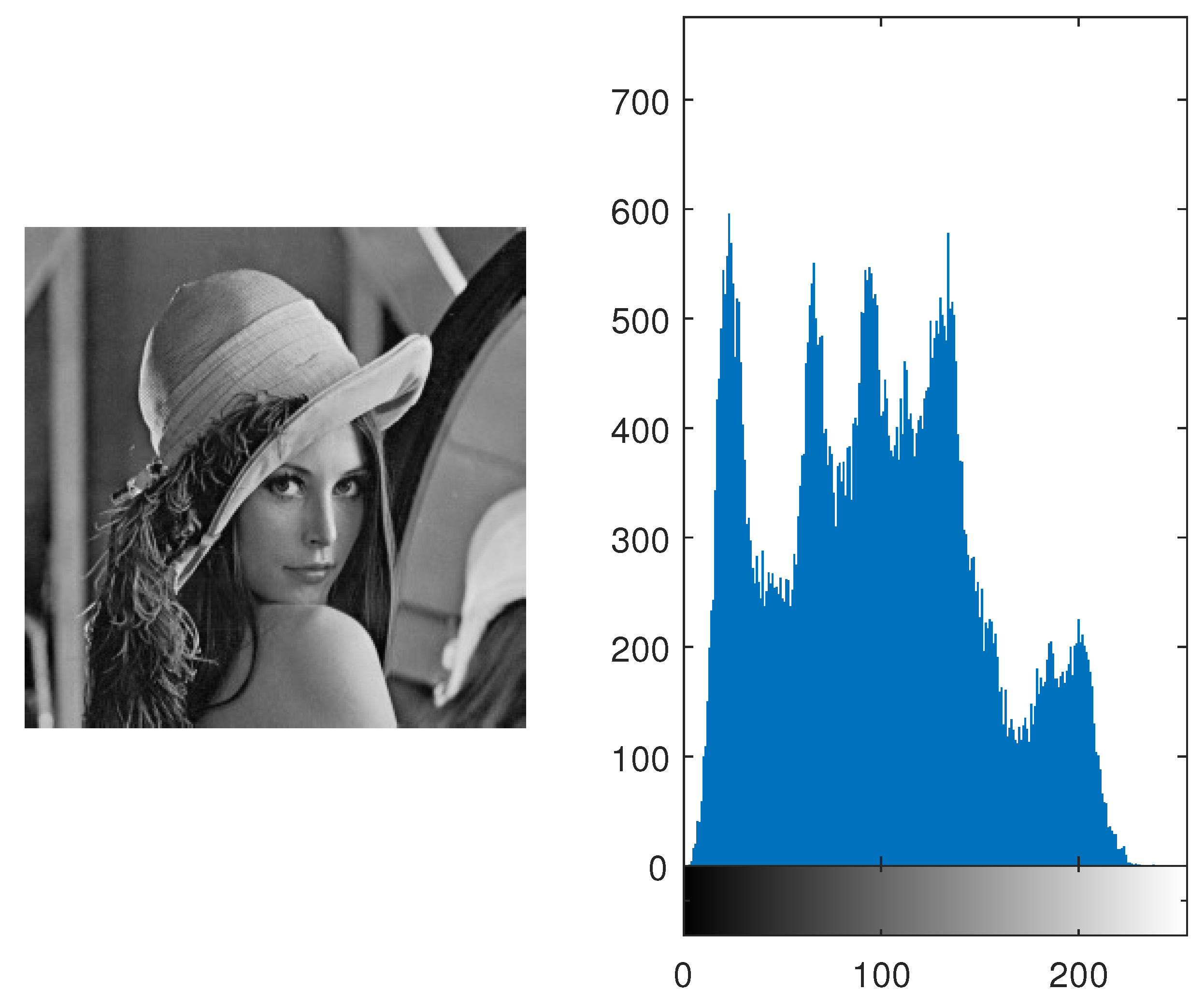
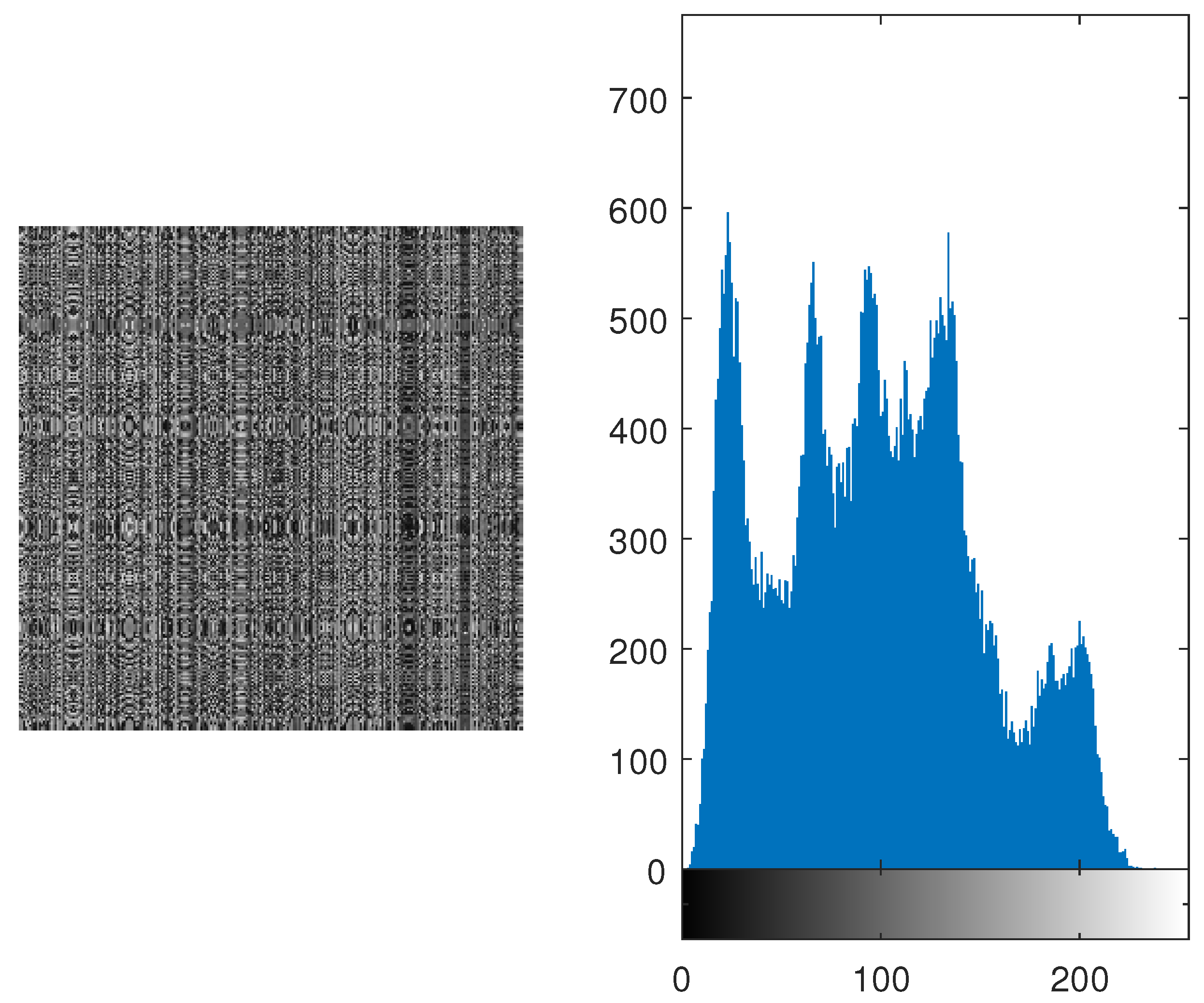
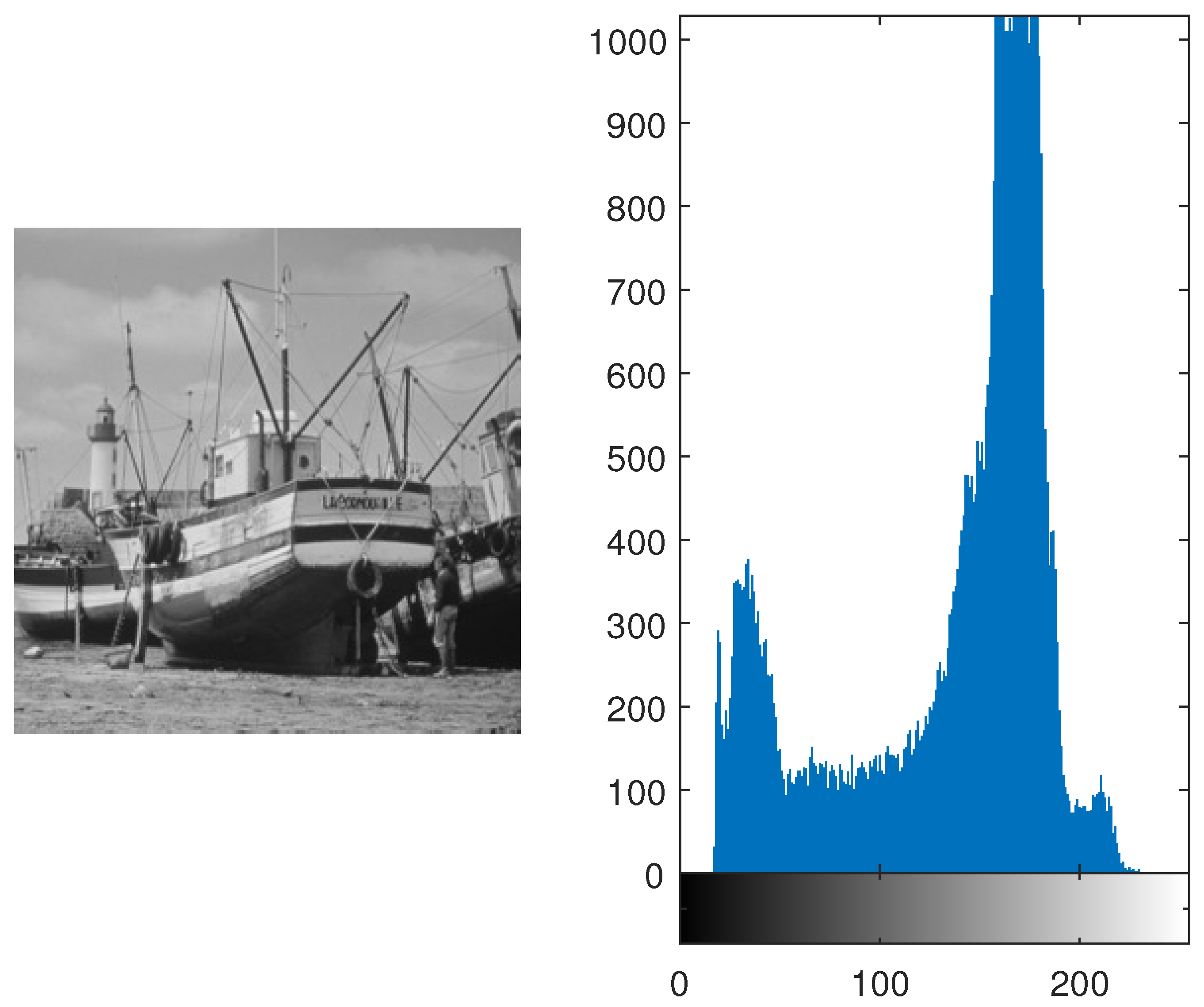
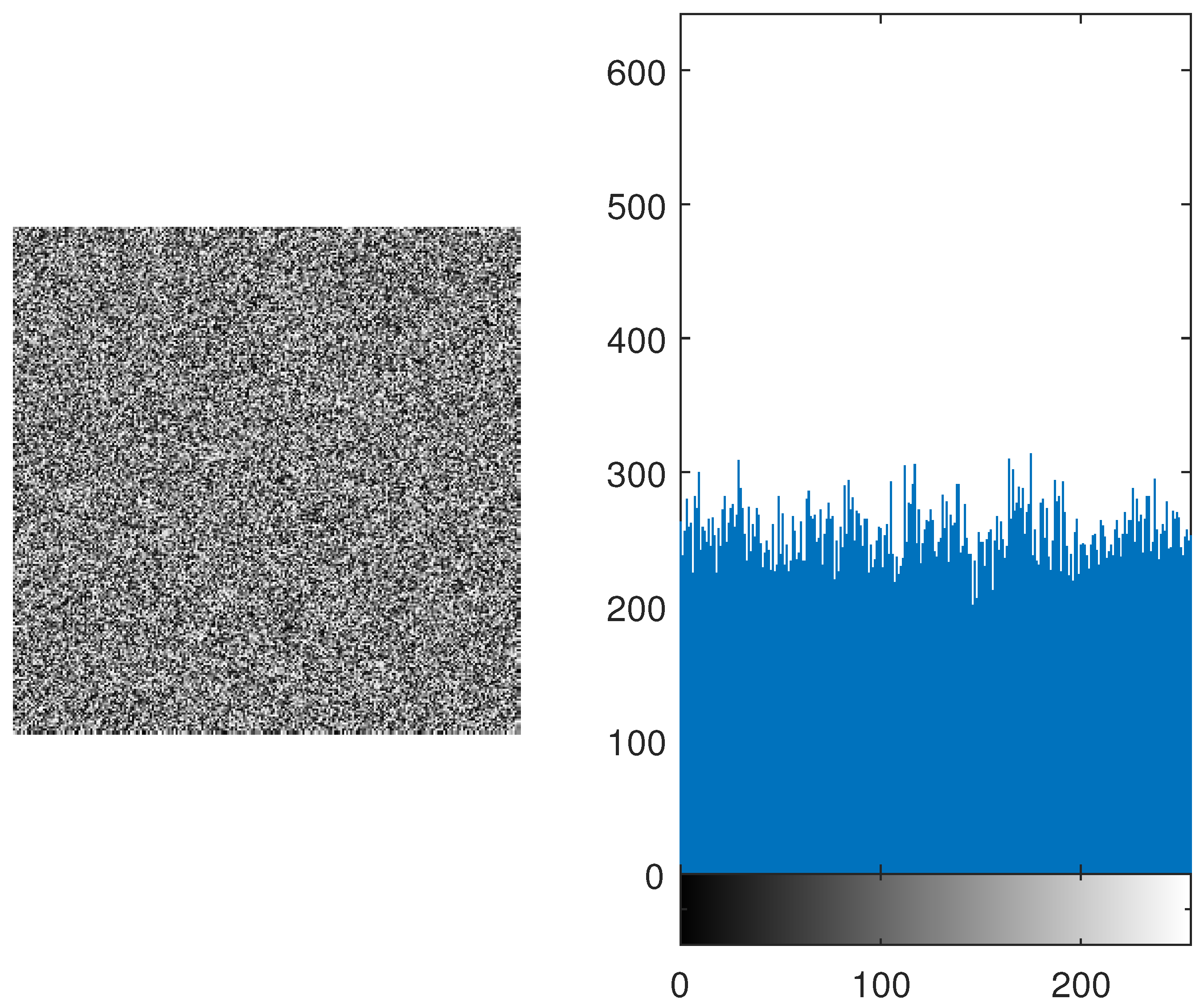
4.3. Histogram Analysis

This analysis is performed to check whether the encrypted image represents any resemblance toward the original image or not. If the histogram of the image is equiprobable, then it is hard for the attackers to know which original image is transmitted. Equal distribution gives no clue to the hackers and it increases the security of the algorithm. The original images of Lena and Boat along with their histograms are shown in Figure 4 and Figure 10. Furthermore, the histogram is equally distributed as shown in Figure 11 and Figure 12. Therefore, it makes it hard for the hackers to retrieve the original message.

4.4. Entropy Analysis

Entropy gives us the measure of randomness and distortion within the gray values of the image [49]. In order to achieve an ideal distribution, the entropy should be equal to 8 [50]. In this proposed algorithm, the entropy of various images is found and is close to 8. The entropy of various images is given in Table 7. In Table 8, the entropy of the proposed algorithm is compared with AES [51] and one of its variations [51]. It is verified that the average entropy of the algorithm is better than AES and much closer to 8.

4.5. Mean of Absolute Deviation (MAD) Analysis

If the difference between the input image and the encrypted image is high, then it becomes more difficult for the hackers to decode the data. MAD analysis gives us the quantified value of how much of the encrypted image is displaced from the input image [52,53]. MAD is determined to compute the difference between two images. MAD can be mathematically represented as follows:
M A D = 1 B × H y = 1 L x = 1 L | O x y C x y |
where
  • O x y = pixels of the original image at the ( x , y ) position;
  • C x y = pixels of the encrypted image at the ( x , y ) position;
  • B = breadth of the image;
  • H = height of the image.
MAD analyses of various images are performed, and the results are compiled in Table 9.

4.6. Correlation Analysis

Correlation is the measure of the dependency of one image on another. Every algorithm designer tries to reduce the dependency. It will be harder for a hacker to perform any kind of malicious activity. Therefore, it is essential in increasing the algorithm’s security. It is computed by the following equation:
c o r r ( O , C ) = E ( ( O μ o ) ( C μ c ) ) σ o σ c
where
  • c o r r ( O , C ) = correlation between the original image and its encrypted image;
  • O = original image;
  • C = cipher image;
  • μ o = mean of the original image;
  • μ c = mean of the encrypted image;
  • E = expected value operator;
  • σ o = standard deviation of the original image;
  • σ c = standard deviation of the cipher image.
Table 10 gives the correlation between various original images and their cipher images. It is evident from Table 10 that the correlation is less than 1%. Also in Table 11, the correlations of AES and its variations are compared with our proposed algorithm. It is verified that the correlation of the proposed algorithm is less than 1%. Therefore, it shows that it is hard for the hackers to determine the original image from the cipher image.

4.7. Contrast Analysis

This provides the user with an identification of the textures of two images. This analysis allows the user to identify any resemblance of texture between two separate images [54,55]. If the texture of an original image and its encrypted image has any closeness of texture between them, it computes contrast using Equation (9). In this equation, it is clearly visible that a co-occurrence matrix is used to compute contrast value. This basically gives any kind of resemblance between any neighboring pixels of the same image. It is mathematically represented as follows:
C = x , y | x y | 2 p ( x , y ) B × H
where
  • p x , y = gray-level co-occurrence matrix;
  • B = breadth of p ( x , y ) ;
  • H = height of p x , y .
  • x , y represents the location of elements within p x , y .
In Table 12, it is evident that the proposed algorithm encrypts any two or more images and that those encrypted images have the same contrast value. This shows that it is harder for any hacker or intruder to compromise the security of the proposed algorithm.
Contrast analysis is performed with various encryption algorithms, which are given in Table 13. It is shown that the proposed algorithm is good at hiding the features and information inside an input image.

4.8. Homogeneity

This measures the closeness of elements within a specified image. This analysis shows how the neighboring elements of a pixel are related to each other. This method is based on the distribution of any pixel with respect to its neighboring pixels. It gives the statistical distribution over the whole image.
The homogeneity can be determined using the following relation:
x , y p x , y 1 + x y
where
  • p x , y = gray-level co-occurrence matrix.
  • x , y represents the location of elements within p x , y .
This test is applied on various images of different sizes. Some of the values are given in Table 14 along with different image sizes. The proposed encryption algorithm gives the homogeneity value around 38–40%. It is also hard for the hacker to determine the original image from the encrypted image.

4.9. Comparative Analysis with the Other Encryption Algorithms

A substantial amount of experimentation has been performed on the proposed algorithm to compare them with the other encryption methods. Table 15 gives a comparison between the proposed algorithm and other encryption algorithms. In this table, the encryption time is given for the 512 × 512 image and the unit is seconds.
The table proves the following:
  • NoPCR of the proposed algorithm proves that 99% of the information inside the input image is scattered in the encrypted image
  • UAPCI proves that there is a 10% average change in the encrypted image as compared to others, which are 33%. This makes the encryption algorithm more robust against differential attacks, consequently enhancing its security.
  • The entropy of an 8-bit image is 8 if and only if all the information present in it is uniformly and evenly distributed. Therefore, entropy close to 8 is preferable. Table 7, Table 8 and Table 15 prove that the entropy of the proposed algorithm is close to 8.
  • Correlation is a measure that tells us how an image is related to another. The correlation value of our proposed algorithm is 0.28%, which is very minute. Therefore, it proves that the encryption algorithm is good at hiding information of the input image.
  • The encryption time is calculated for a 512 × 512 image. The results show that it takes 15 ms to complete the encryption process. Therefore, it is shown here that the algorithm takes less time for the encryption in comparison to others.

5. Conclusions

In this study, an image encryption algorithm is proposed that is based on CLMs. The algorithm’s security is verified through various tests, which include keyspace analysis, complexity analysis, sensitivity analysis, strict avalanche criteria, histogram analysis, entropy analysis, mean of absolute deviation analysis, correlation analysis, contrast analysis and homogeneity. These tests show a high level of security in image encryption applications. Researchers/practitioners can use the proposed encryption algorithm in different fields, such as image encryption, data encryption, audio/video encryption. etc.

Author Contributions

Methodology, M.R. and H.M.; Software, M.R.; Validation, M.R. and H.D.; Formal analysis, M.R., S.N. and H.M.; Investigation, H.D. and S.N.; Resources, H.D., S.N., A.A., J.K. and I.B.B.; Data curation, A.A. and J.K.; Writing—original draft, M.R. and T.A.; Writing—review & editing, H.D., H.M. and A.A.; Visualization, T.A.; Supervision, H.M. and T.A.; Project administration, H.M. and T.A.; Funding acquisition, T.A. All authors have read and agreed to the published version of the manuscript.

Funding

This work received no funding from any source.

Institutional Review Board Statement

Not applicable.

Informed Consent Statement

Not applicable.

Data Availability Statement

Data are contained within the article.

Conflicts of Interest

The authors declare no conflicts of interest.

Abbreviations

The following abbreviations are used in this manuscript:
MADMean of Absolute Deviation
SACStrict Avalanche Criteria
NoPCRNumber of Pixels Change Rate
UAPCIUnified Average Pixel Changing Intensity

References

  1. Su, Z.; Zhang, G.; Jiang, J. Multimedia security: A survey of chaos-based encryption technology. In Multimedia—A Multidisciplinary Approach to Complex Issues; InTech: Rijeka, Croatia, 2012. [Google Scholar]
  2. Shannon, C.E. Communication theory of secrecy systems. Bell Syst. Tech. J. 1949, 28, 656–715. [Google Scholar] [CrossRef]
  3. Wu, W.; Wang, Q. Quantum image encryption based on Baker map and 2D logistic map. Int. J. Theor. Phys. 2022, 61, 64. [Google Scholar] [CrossRef]
  4. Liu, X.; Xiao, D.; Liu, C. Three-level quantum image encryption based on Arnold transform and logistic map. Quantum Inf. Process. 2021, 20, 1–22. [Google Scholar] [CrossRef]
  5. Hu, W.W.; Zhou, R.G.; Jiang, S.; Liu, X.; Luo, J. Quantum image encryption algorithm based on generalized Arnold transform and Logistic map. CCF Trans. High Perform. Comput. 2020, 2, 228–253. [Google Scholar] [CrossRef]
  6. Xu, J.; Li, P.; Yang, F.; Yan, H. High intensity image encryption scheme based on quantum logistic chaotic map and complex hyperchaotic system. IEEE Access 2019, 7, 167904–167918. [Google Scholar] [CrossRef]
  7. Abd El-Latif, A.A.; Li, L.; Wang, N.; Han, Q.; Niu, X. A new approach to chaotic image encryption based on quantum chaotic system, exploiting color spaces. Signal Process. 2013, 93, 2986–3000. [Google Scholar] [CrossRef]
  8. Biryukov, A. Substitution–Permutation (SP) Network. In Encyclopedia of Cryptography and Security; van Tilborg, H.C.A., Jajodia, S., Eds.; Springer US: Boston, MA, USA, 2011; p. 1268. [Google Scholar] [CrossRef]
  9. Biyashev, R.G.; Kapalova, N.A.; Dyusenbayev, D.S.; Algazy, K.T.; Wojcik, W.; Smolarz, A. Development and analysis of symmetric encryption algorithm Qamal based on a substitution-permutation network. Int. J. Electron. Telecommun. 2021, 67, 127–132. [Google Scholar] [CrossRef]
  10. Ni, Z.; Kang, X.; Wang, L. A novel image encryption algorithm based on bit-level improved Arnold transform and hyper chaotic map. In Proceedings of the 2016 IEEE International Conference on Signal and Image Processing (ICSIP), Beijing, China, 13–15 August 2016; IEEE: Toulouse, France, 2016; pp. 156–160. [Google Scholar]
  11. Singh, P.; Yadav, A.; Singh, K. Phase image encryption in the fractional Hartley domain using Arnold transform and singular value decomposition. Opt. Lasers Eng. 2017, 91, 187–195. [Google Scholar] [CrossRef]
  12. Fu, C.; Chen, J.j.; Zou, H.; Meng, W.h.; Zhan, Y.f.; Yu, Y.W. A chaos-based digital image encryption scheme with an improved diffusion strategy. Opt. Express 2012, 20, 2363–2378. [Google Scholar] [CrossRef] [PubMed]
  13. Zhang, Y.Q.; Wang, X.Y. Spatiotemporal chaos in mixed linear–nonlinear coupled logistic map lattice. Phys. A Stat. Mech. Its Appl. 2014, 402, 104–118. [Google Scholar] [CrossRef]
  14. Zhu, Z.l.; Zhang, W.; Wong, K.w.; Yu, H. A chaos-based symmetric image encryption scheme using a bit-level permutation. Inf. Sci. 2011, 181, 1171–1186. [Google Scholar] [CrossRef]
  15. Hua, Z.; Zhou, Y. Image encryption using 2D Logistic-adjusted-Sine map. Inf. Sci. 2016, 339, 237–253. [Google Scholar] [CrossRef]
  16. Liu, L.; Miao, S. An image encryption algorithm based on Baker map with varying parameter. Multimed. Tools Appl. 2017, 76, 16511–16527. [Google Scholar] [CrossRef]
  17. Liu, W.; Sun, K.; Zhu, C. A fast image encryption algorithm based on chaotic map. Opt. Lasers Eng. 2016, 84, 26–36. [Google Scholar] [CrossRef]
  18. Chai, X.; Chen, Y.; Broyde, L. A novel chaos-based image encryption algorithm using DNA sequence operations. Opt. Lasers Eng. 2017, 88, 197–213. [Google Scholar] [CrossRef]
  19. Wang, X.; Zhang, H.l. A novel image encryption algorithm based on genetic recombination and hyper-chaotic systems. Nonlinear Dyn. 2016, 83, 333–346. [Google Scholar] [CrossRef]
  20. Wang, X.Y.; Zhang, Y.Q.; Bao, X.M. A novel chaotic image encryption scheme using DNA sequence operations. Opt. Lasers Eng. 2015, 73, 53–61. [Google Scholar] [CrossRef]
  21. Zhou, N.; Hu, Y.; Gong, L.; Li, G. Quantum image encryption scheme with iterative generalized Arnold transforms and quantum image cycle shift operations. Quantum Inf. Process. 2017, 16, 1–23. [Google Scholar] [CrossRef]
  22. Wang, X.; Zhu, X.; Wu, X.; Zhang, Y. Image encryption algorithm based on multiple mixed hash functions and cyclic shift. Opt. Lasers Eng. 2018, 107, 370–379. [Google Scholar] [CrossRef]
  23. Kulsoom, A.; Xiao, D.; Abbas, S.A. An efficient and noise resistive selective image encryption scheme for gray images based on chaotic maps and DNA complementary rules. Multimed. Tools Appl. 2016, 75, 1–23. [Google Scholar] [CrossRef]
  24. Wang, L.; Song, H.; Liu, P. A novel hybrid color image encryption algorithm using two complex chaotic systems. Opt. Lasers Eng. 2016, 77, 118–125. [Google Scholar] [CrossRef]
  25. Wang, X.; Liu, C.; Xu, D.; Liu, C. Image encryption scheme using chaos and simulated annealing algorithm. Nonlinear Dyn. 2016, 84, 1417–1429. [Google Scholar] [CrossRef]
  26. Wang, X.; Liu, C.; Zhang, H. An effective and fast image encryption algorithm based on Chaos and interweaving of ranks. Nonlinear Dyn. 2016, 84, 1595–1607. [Google Scholar] [CrossRef]
  27. Wang, X.; Zhu, X.; Zhang, Y. An image encryption algorithm based on Josephus traversing and mixed chaotic map. IEEE Access 2018, 6, 23733–23746. [Google Scholar] [CrossRef]
  28. Wang, X.; Feng, L.; Zhao, H. Fast image encryption algorithm based on parallel computing system. Inf. Sci. 2019, 486, 340–358. [Google Scholar] [CrossRef]
  29. Jain, R.; Sharma, J. Symmetric color image encryption algorithm using fractional DRPM and chaotic baker map. In Proceedings of the 2016 IEEE International Conference on Recent Trends in Electronics, Information & Communication Technology (RTEICT), Bangalore, India, 20–21 May 2016; IEEE: Toulouse, France, 2016; pp. 1835–1840. [Google Scholar]
  30. Wang, X.; Zhang, H.l. A color image encryption with heterogeneous bit-permutation and correlated chaos. Opt. Commun. 2015, 342, 51–60. [Google Scholar] [CrossRef]
  31. Wu, X.; Wang, D.; Kurths, J.; Kan, H. A novel lossless color image encryption scheme using 2D DWT and 6D hyperchaotic system. Inf. Sci. 2016, 349, 137–153. [Google Scholar] [CrossRef]
  32. Xu, L.; Li, Z.; Li, J.; Hua, W. A novel bit-level image encryption algorithm based on chaotic maps. Opt. Lasers Eng. 2016, 78, 17–25. [Google Scholar] [CrossRef]
  33. Liu, H.; Wang, X.; Kadir, A. Image encryption using DNA complementary rule and chaotic maps. Appl. Soft Comput. 2012, 12, 1457–1466. [Google Scholar] [CrossRef]
  34. Zhang, Y.Q.; Wang, X.Y.; Liu, J.; Chi, Z.L. An image encryption scheme based on the MLNCML system using DNA sequences. Opt. Lasers Eng. 2016, 82, 95–103. [Google Scholar] [CrossRef]
  35. Anees, A.; Siddiqui, A.M.; Ahmed, F. Chaotic substitution for highly autocorrelated data in encryption algorithm. Commun. Nonlinear Sci. Numer. Simul. 2014, 19, 3106–3118. [Google Scholar] [CrossRef]
  36. Arif, J.; Khan, M.A.; Ghaleb, B.; Ahmad, J.; Munir, A.; Rashid, U.; Al-Dubai, A.Y. A novel chaotic permutation-substitution image encryption scheme based on logistic map and random substitution. IEEE Access 2022, 10, 12966–12982. [Google Scholar] [CrossRef]
  37. Alawida, M. A novel chaos-based permutation for image encryption. J. King Saud Univ. Comput. Inf. Sci. 2023, 35, 101595. [Google Scholar] [CrossRef]
  38. Hussain, I.; Anees, A.; Al-Maadeed, T.A. A novel encryption algorithm using multiple semifield S-boxes based on permutation of symmetric group. Comput. Appl. Math. 2023, 42, 80. [Google Scholar] [CrossRef]
  39. Lorenz, E.N. The problem of deducing the climate from the governing equations. Tellus 1964, 16, 1–11. [Google Scholar] [CrossRef]
  40. Riaz, M.; Ahmed, J.; Shah, R.A.; Hussain, A. Novel secure pseudorandom number generator based on duffing map. Wirel. Pers. Commun. 2018, 99, 85–93. [Google Scholar] [CrossRef]
  41. Agrawal, V.; Agrawal, S.; Deshmukh, R. Analysis and review of encryption and decryption for secure communication. Int. J. Sci. Eng. Res. 2014, 2, 2347–3878. [Google Scholar]
  42. SIPI Image Database—Sipi.usc.edu. Available online: http://sipi.usc.edu/database/database.php (accessed on 19 September 2023).
  43. Mishra, M.; Mankar, V. A Chaotic encryption algorithm: Robustness against Brute-force attack. In Advances in Computer Science, Engineering & Applications; Springer: Berlin/Heidelberg, Germany, 2012; pp. 169–179. [Google Scholar]
  44. Kamat, V.G.; Sharma, M. Symmetric Image Encryption Algorithm Using 3D Rossler System. Int. J. Comput. Sci. Bus. Inform. 2014, 14, 2145–2152. [Google Scholar]
  45. Radwan, A.G.; AbdElHaleem, S.H.; Abd-El-Hafiz, S.K. Symmetric encryption algorithms using chaotic and non-chaotic generators: A review. J. Adv. Res. 2016, 7, 193–208. [Google Scholar] [CrossRef]
  46. Motara, Y.M.; Irwin, B. Sha-1 and the strict avalanche criterion. In Proceedings of the 2016 Information security for South Africa (ISSA), Johannesburg, South Africa, 17–18 August 2016; IEEE: Toulouse, France, 2016; pp. 35–40. [Google Scholar]
  47. Mar, P.P.; Latt, K.M. New analysis methods on strict avalanche criterion of S-boxes. World Acad. Sci. Eng. Technol. 2008, 48, 25. [Google Scholar]
  48. Hussain, I.; Shah, T.; Gondal, M.A.; Wang, Y. Analyses of SKIPJACK S-box. World Appl. Sci. J. 2011, 13, 2385–2388. [Google Scholar]
  49. Zhen, P.; Zhao, G.; Min, L.; Jin, X. Chaos-based image encryption scheme combining DNA coding and entropy. Multimed. Tools Appl. 2016, 75, 6303–6319. [Google Scholar] [CrossRef]
  50. Wu, Y.; Noonan, J.P.; Agaian, S. A novel information entropy based randomness test for image encryption. In Proceedings of the 2011 IEEE International Conference on Systems, Man, and Cybernetics, Anchorage, AK, USA, 9–12 October 2011; IEEE: Toulouse, France, 2011; pp. 2676–2680. [Google Scholar]
  51. Zeghid, M.; Machhout, M.; Khriji, L.; Baganne, A.; Tourki, R. A modified AES based algorithm for image encryption. Int. J. Comput. Inf. Eng. 2007, 1, 745–750. [Google Scholar]
  52. Högel, J.; Schmid, W.; Gaus, W. Robustness of the standard deviation and other measures of dispersion. Biom. J. 1994, 36, 411–427. [Google Scholar] [CrossRef]
  53. Mazumder, S.; Serfling, R. Bahadur representations for the median absolute deviation and its modifications. Stat. Probab. Lett. 2009, 79, 1774–1783. [Google Scholar] [CrossRef]
  54. Pizolato, J.C., Jr.; Neto, L.G. Phase-only optical encryption based on the zeroth-order phase-contrast technique. Opt. Eng. 2009, 48, 098201. [Google Scholar]
  55. Bibi, N.; Farwa, S.; Muhammad, N.; Jahngir, A.; Usman, M. A novel encryption scheme for high-contrast image data in the Fresnelet domain. PLoS ONE 2018, 13, e0194343. [Google Scholar] [CrossRef]
  56. Hua, Z.; Jin, F.; Xu, B.; Huang, H. 2D Logistic-Sine-coupling map for image encryption. Signal Process. 2018, 149, 148–161. [Google Scholar] [CrossRef]
  57. Gao, S.; Wu, R.; Wang, X.; Liu, J.; Li, Q.; Wang, C.; Tang, X. Asynchronous updating Boolean network encryption algorithm. In IEEE Transactions on Circuits and Systems for Video Technology; IEEE: Toulouse, France, 2023. [Google Scholar]
Figure 1. Encryption model.
Information 15 00172 g001
Figure 2. Flowchart of encryption process.
Information 15 00172 g002
Figure 3. Bifurcation diagram of modified CLM.
Information 15 00172 g003
Figure 4. Lena image and its histogram.
Information 15 00172 g004
Figure 5. Permuted image of Lena and its histogram depicting that the substituted image does not resemble the original image.
Information 15 00172 g005
Figure 6. Substituted image of Lena and its histogram showing no information regarding original image.
Information 15 00172 g006
Figure 7. No. of bits vs. no. of combinations graph depicting exponential growth.
Information 15 00172 g007
Figure 8. Encrypted image and its histogram.
Information 15 00172 g008
Figure 9. Flowchart of decryption process.
Information 15 00172 g009
Figure 10. Original boat image and its histogram depicting various peaks in the pixel intensities.
Information 15 00172 g010
Figure 11. Encrypted Lena image and its histogram.
Information 15 00172 g011
Figure 12. Encrypted boat image with histogram showing that all pixels are almost uniformally distributed.
Information 15 00172 g012
Table 1. Input pixel intensities for substitution.
0123456789101112131415
16171819202122232425262728293031
32333435363738394041424344454647
48495051525354555657585960616263
64656667686970717273747576777879
80818283848586878889909192939495
96979899100101102103104105106107108109110111
112113114115116117118119120121122123124125126127
128129130131132133134135136137138139140141142143
144145146147148149150151152153154155156157158159
160161162163164165166167168169170171172173174175
176177178179180181182183184185186187188189190191
192193194195196197198199200201202203204205206207
208209210211212213214215216217218219220221222223
224225226227228229230231232233234235236237238239
240241242243244245246247248249250251252253254255
Table 2. Pixels arranged in random order based on CLM with population growth at 5.5 .
02452231901469125204116171634216623125216
40109167214250193336289235194142795176
80229111238982034112419615190118135141136
1209355620213149212108249123242941912196
1602132553050595744202411951387024715756
200771995415424365132188233113446473716
240197143782171732201002258318622103173232
246187102106998152122171558225415953192
64181311262102789140180209227234230215189152
10445231150582119722892201431302061569112
144165175174162139105604193115261827120572
1842911919810671131481721851871781581278532
2241496322211425112123684177374134183221248
81372462181791296825216975226110239101208
4813320714661071371561641611471228639237168
88253151381703514524476153219186295117128
Table 3. Complexity analysis of different permutation algorithms with the proposed algorithm.
AlgorithmsSpace ComplexityPermutation Time
256 × 256512 × 5121024 × 1024
Proposed Algorithm O ( m + n ) 1.5 ms6 ms18 ms
Ref. [15] O ( m × n ) 20 ms80 ms330 ms
Ref. [22] O ( 1 ) 4 ms16 ms68 ms
Ref. [28] O ( m + n ) 2.5 ms10 ms42 ms
Table 4. NoPCR.
Table 4. NoPCR.
Image NameNoPCR
Lena (256,256)99.2282
Black Image (All zeros)99.2282
Cameraman (256,256)99.2282
Baboon (512,512)99.4743
White Image (All ones)99.2282
Peppers (512,512)99.4742
Random Image [0 255]99.2282
Barbara (512,512)99.4743
Lena (512,512)99.4804
Table 5. UAPCI.
Table 5. UAPCI.
Image NameUAPCI
Lena (256,256)12.5527
Black Image (All zeros)18.5472
Cameraman (256,256)12.1591
Baboon (512,512)7.2304
White Image (All ones)6.5406
Peppers (512,512)7.1747
Random Image [0 255]12.5526
Barbara (512,512)7.2447
Lena (512,512)7.1499
Table 6. SAC comparison of various algorithms.
S-BoxesSAC
Proposed S-box0.491
AES [48]0.504
APA [48]0.5
Gray [48]0.499
S8 AES [48]0.504
Skipjack [48]0.503
Xyi [48]0.502
Prime [48]0.516
Table 7. Entropy of various images.
Image NameOriginal ImageCipher Image
Lena (256,256)7.56837.9956
Lena (512,512)7.43187.9956
Cameraman (256,256)7.00977.9907
Black Image (All zeros)07.6822
Barbara (512,512)7.39257.9960
White Image (All ones)07.6822
Peppers (512,512)7.57007.9958
Random Image [0 255]7.99517.9972
Baboon (512,512)7.22887.9952
Table 8. Entropy of various algorithms.
AlgorithmEntropy
Proposed Algorithm7.9952
AES [51]7.91
AES+A5/1 [51]7.96
Table 9. MAD analysis of various images.
Image NameMAD
Lena (256,256)77.90740
Lena (512,512)72.82140
Cameraman (256,256)79.01410
Black Image (All zeros)127.9119
Barbara (512,512)72.60550
White Image (All ones)127.0529
Peppers (512,512)78.51690
Random Image [0 255]85.23000
Baboon (512,512)69.36040
Table 10. Correlation of various images.
Image NameCorrelation Value
Lena (256,256)0.0021
Black Image (All zeros)NaN
Cameraman (256,256)−0.0048
Baboon (512,512)0.001
White Image (All ones)NaN
Peppers (512,512)−0.0027
Random Image [0 255]−0.000542209
Barbara (512,512)0.0016
Lena (512,512)−0.0071
Table 11. Correlation of various algorithms.
AlgorithmCorrelation between Various Algorithms
Proposed Algorithm0.0028
AES [51]0.072
AES+A5/1 [51]0.067
AES+W7 [51]0.025
Table 12. The contrast of various images.
Image NameOriginal ImageCipher Image
Lena (256,256)235255
Black Image (All zeros)0255
Baboon (512,512)203255
White Image (All ones)0255
Peppers (512,512)228255
Lena (512,512)217255
Random Image [0 255]255255
Barbara (512,512)210255
Cameraman (256,256)246255
Table 13. Comparison of contrast with other algorithms.
Encryption AlgorithmContrast
Proposed Algorithm255
Alawida [37]109.2
Hua and Zhou [15]109.23
Hua et al. [56]109.19
Table 14. Homogeneity of various images.
Image NameOriginal ImageCipher Image
Lena (256,256)0.85730.3874
Black Image (All zeros)0.99610.3828
Baboon (512,512)0.79880.3872
White Image (All ones)0.99610.4345
Peppers (512,512)0.89460.3886
Random Image [0 255]0.99610.4345
Barbara (512,512)0.85600.3880
Cameraman (256,256)0.89180.3907
Lena (512,512)0.88130.3899
Table 15. Comparative analysis with the other encryption algorithms.
Statistical TestNoPCRUAPCIEntropyCorrelationEncryption Time
Proposed Algorithm99.48049.57.99520.00280.015
Arif et al. [36]99.6233.497.99940.00331.28
Alawida [37]99.612533.45257.99940.00040.25
Anees et al. [35]0.00150.0017.80260.1221.21
Gao et al. [57]99.610233.44657.9992−0.00010.2205
Disclaimer/Publisher’s Note: The statements, opinions and data contained in all publications are solely those of the individual author(s) and contributor(s) and not of MDPI and/or the editor(s). MDPI and/or the editor(s) disclaim responsibility for any injury to people or property resulting from any ideas, methods, instructions or products referred to in the content.

