


An Interactive Pedagogical Tool for Simulation of Controlled Rectifiers

Abstract
:1. Introduction
2. CORES—Controlled Rectifier Simulator
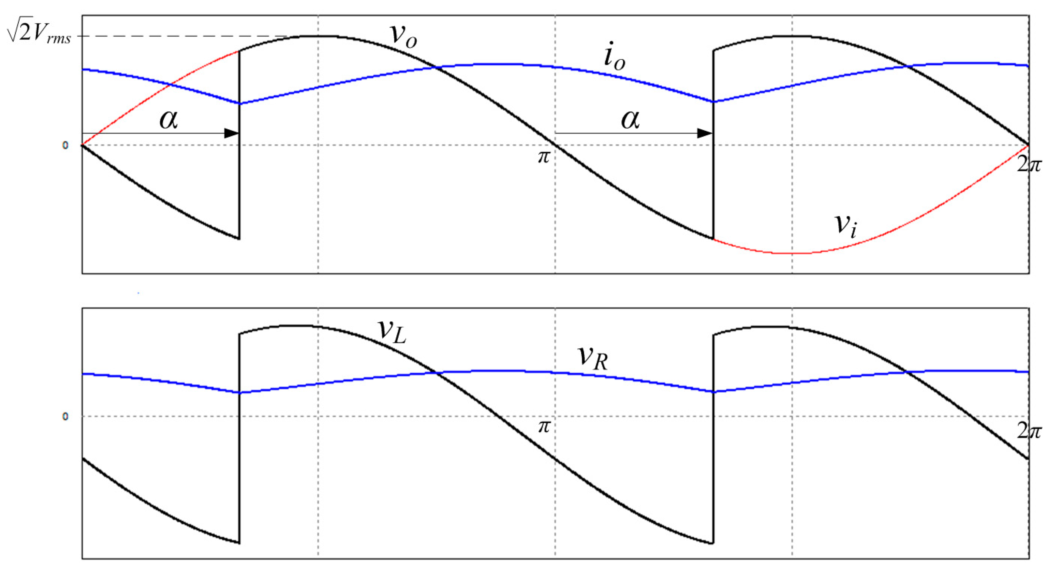
2.1. Rectifiers Theory in CORES
- the number of phases;
- the connection type to the grid;
- the type of semiconductors (diodes and/or thyristors);
- the topology (half or full bridge and semi-controlled or fully-controlled);
- the load characteristics.
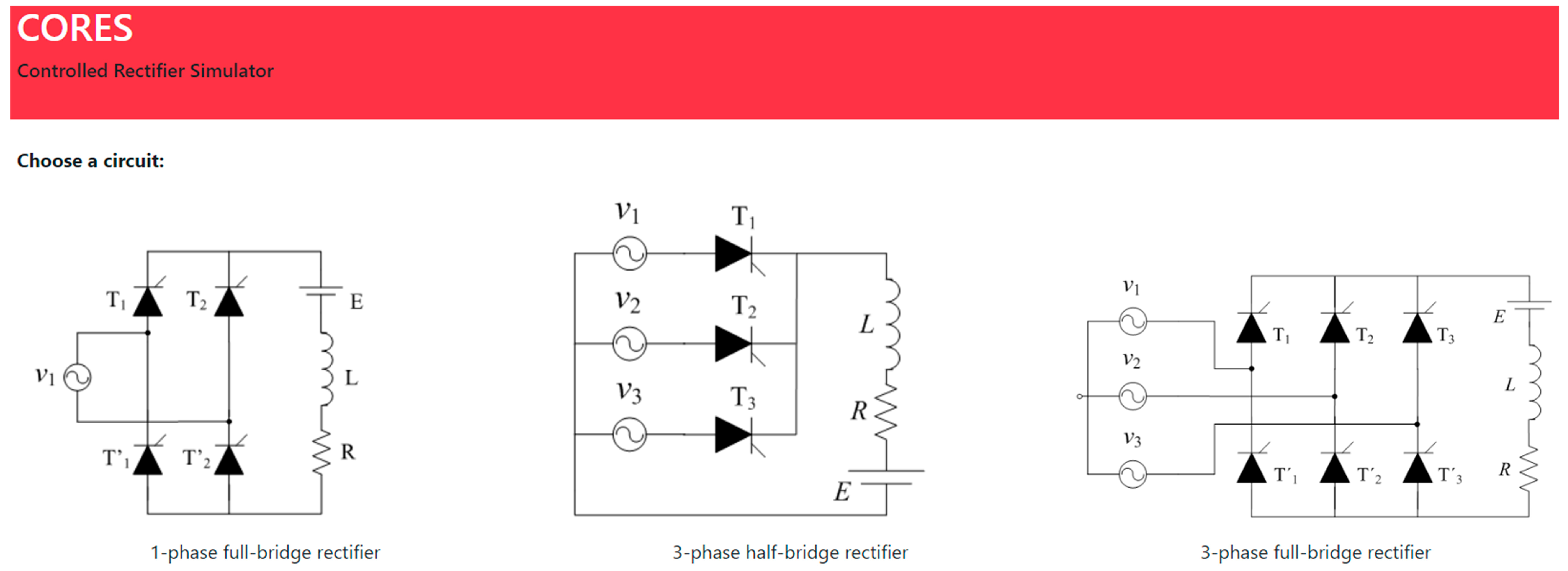
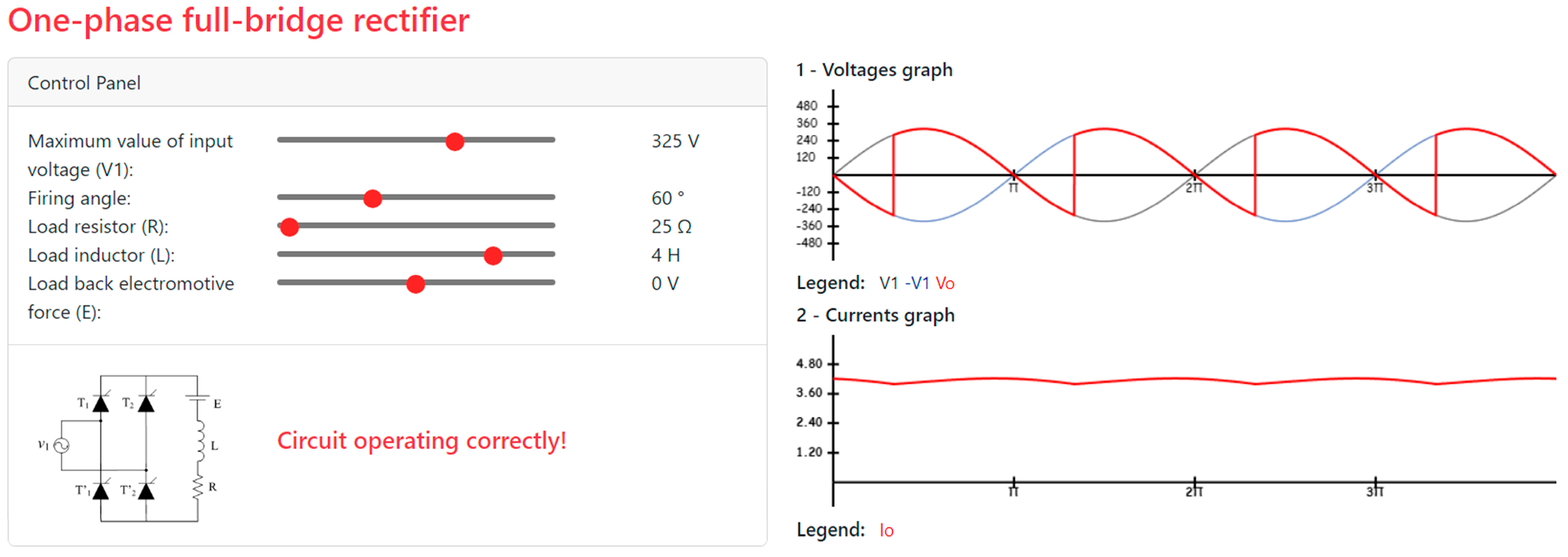
- One-phase full-wave (bridge) rectifier
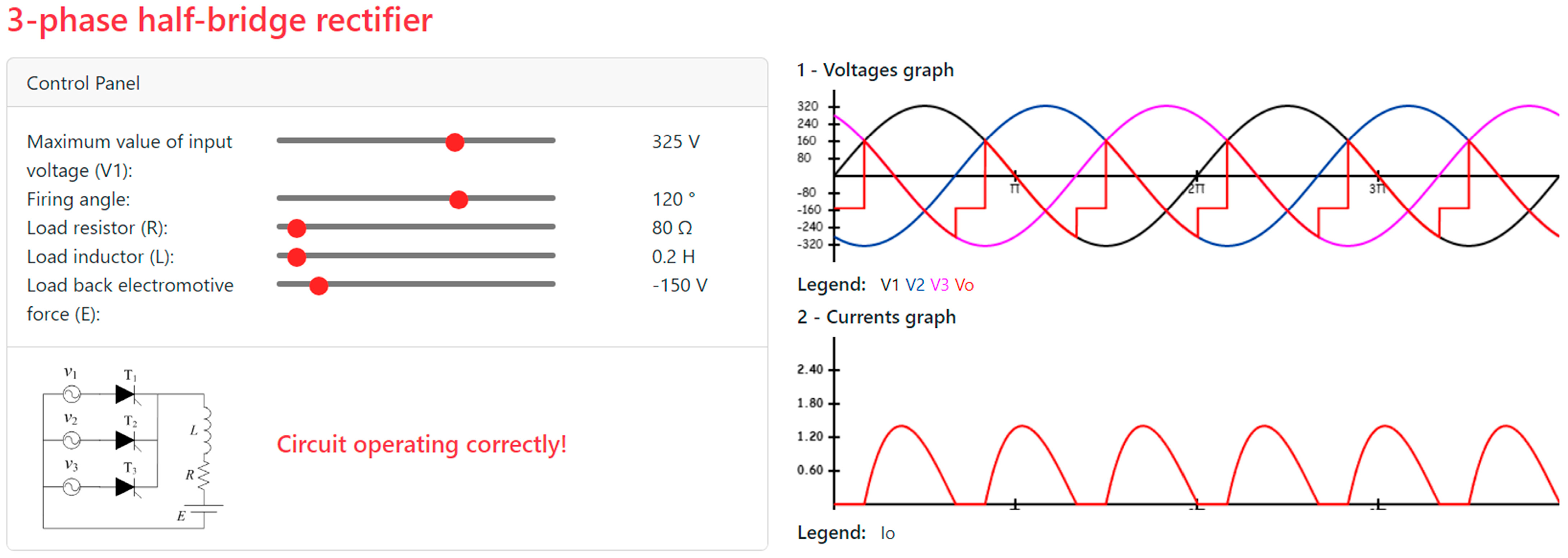
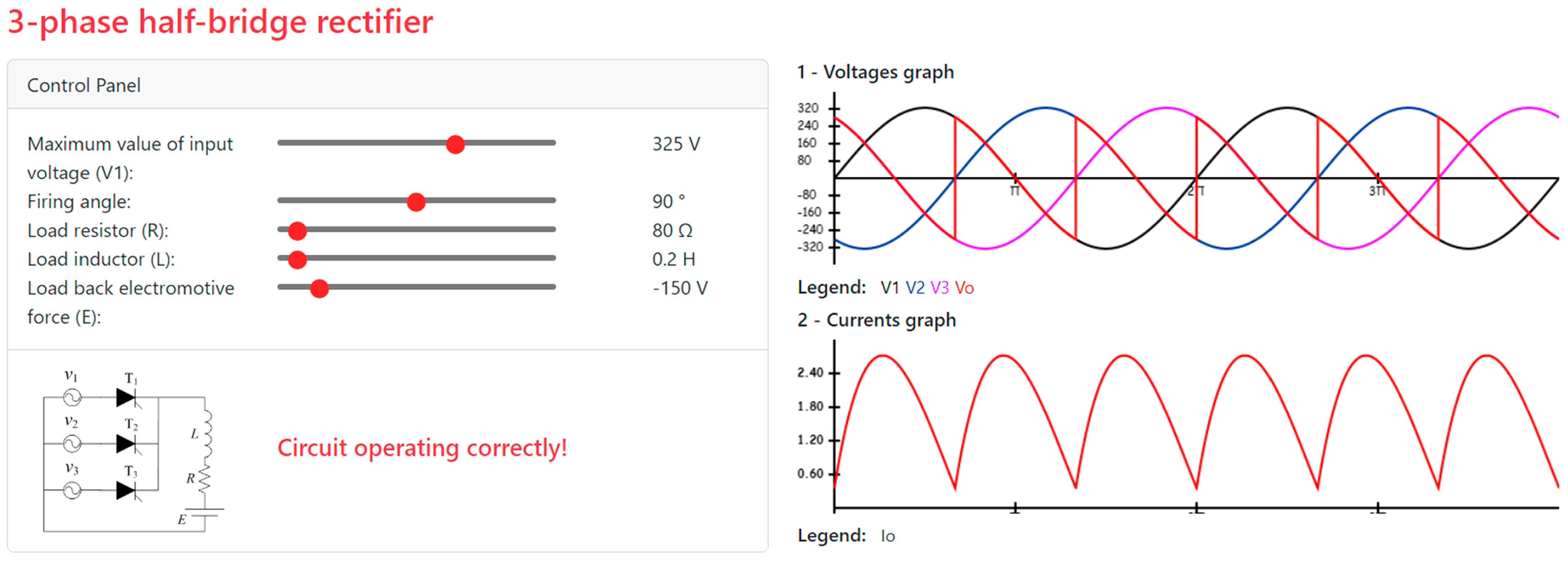
- Three-phase half-bridge rectifier
- Three-phase full-bridge rectifier
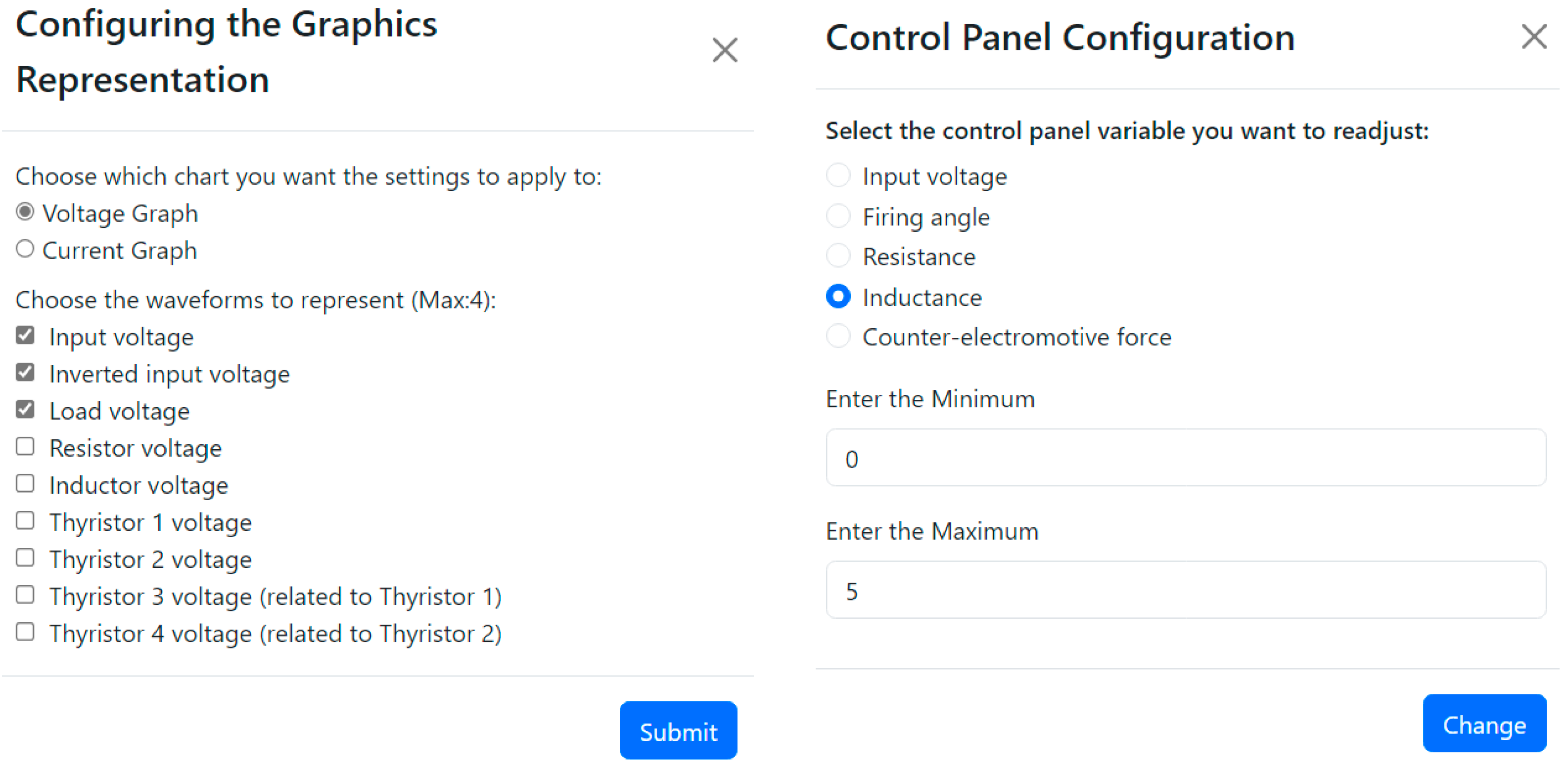
2.2. Application Features
- One-phase full-wave (bridge) rectifier
- Three-phase half-bridge rectifier
- Three-phase full-bridge rectifier
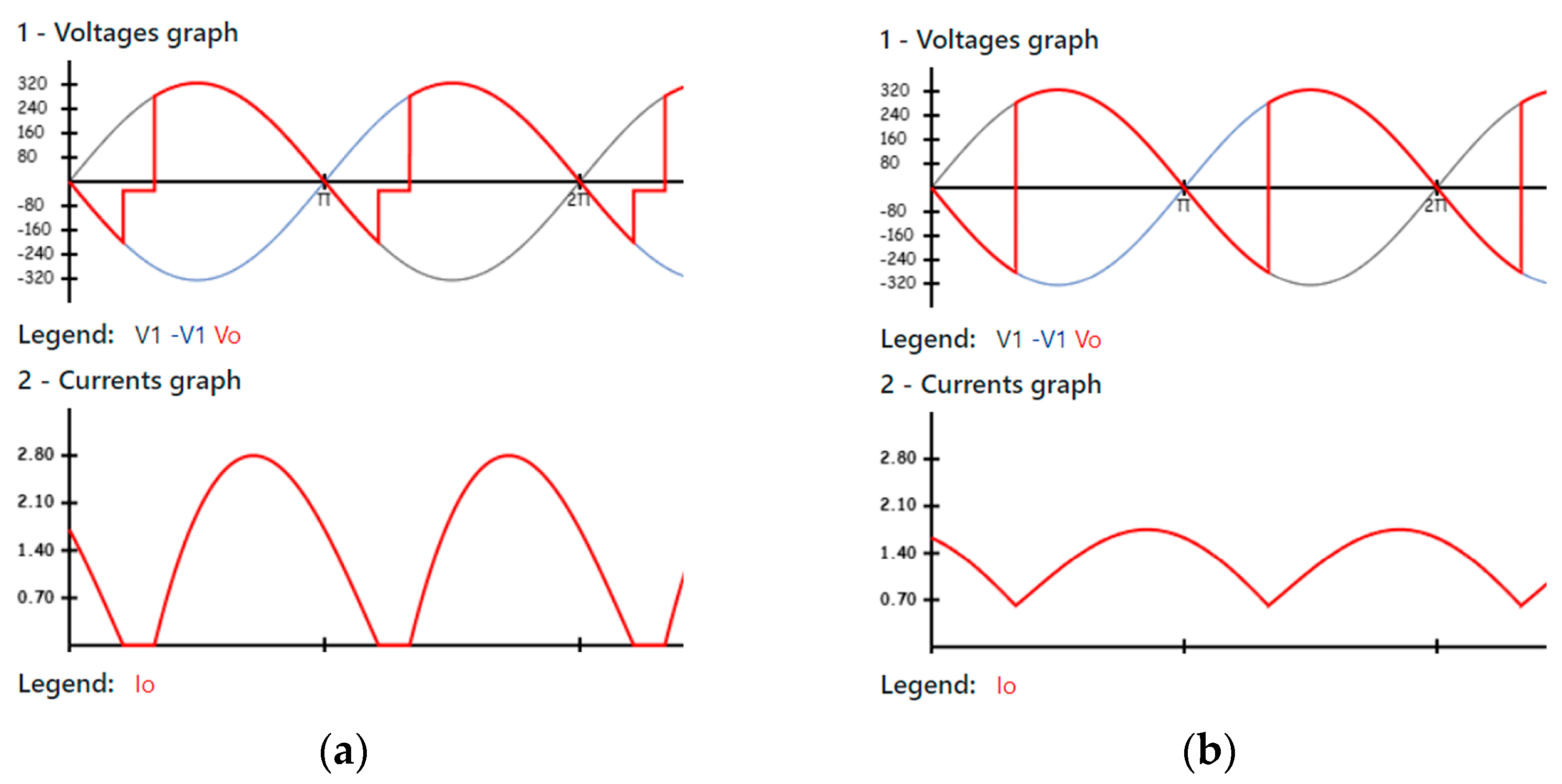
2.3. Examples of CORES Usage
3. Discussion
- 5—fully agree
- 4—partially agree
- 3—neutral
- 2—partially disagree
- 1—fully disagree
- “CORES is easy to understand and use”: this statement received the highest average score, indicating that users find CORES very intuitive and user-friendly. Such a high score reflects well on the system’s design and usability, suggesting that it meets the needs of its users effectively in terms of ease of use and understandability.
- “CORES responds to my actions quickly”: the high score for this statement suggests that CORES is perceived as a responsive system. Quick response to user actions is crucial in ensuring a positive user experience, and this score indicates that CORES is performing well in this aspect.
- “CORES helped me understand the relationship between different parameters”: this statement’s high score reveals that CORES is effective in helping users understand complex relationships between different parameters. This is indicative of good educational value and effective information presentation within the system.
- “In CORES, the thyristor trigger circuit is transparent and understandable”: while still above 4, this statement score indicates that the aspects related to the thyristor trigger circuit in CORES might be somewhat less transparent or understandable compared to other features.
- “CORES helped me understand the process of continuous and discontinuous conduction”: this statement, with a score slightly above 4, suggests that while CORES is helpful in understanding the various conduction regimes, there might be room for improvement in how it conveys this particular aspect.
- “CORES enables the simulation of various circuits effectively”: as the statement with the lowest average score, it indicates that users find the simulation of different circuits in CORES to be less effective compared to other features. This area might benefit from additional attention or enhancement to improve user satisfaction.
- “CORES has the potential to be better than other simulators in the study for power electronics. However, there has to be a strong investment to contemplate all the circuits studied, under penalty of becoming a tool of limited use. In my case, I used it only for the circuits I had but I quickly turned to the PSIM, since I could perform different tests, in order to understand how the circuits work. However, the time spent was considerably longer. The abstraction and speed of use brought by CORES seems very important to me, so if I had all the circuits I would hardly use other simulators (in a less analytical logic, more focused on the influence of the components on the behavior of the circuit)”.
- “The only weak point, from my point of view, will be the fact that there are only the 3 main circuits, so the existence of others would be something valuable”.
- “It would be fruitful to have more diversity and better ability to adjust circuit specificities”.
- “It could have more circuits, or better yet, allow the construction of circuits. Maybe something to put as a job for a next student who can give continuity. I find it a very useful application for the quick understanding of circuits”.
- “CORES is very easy to use and allows you to clearly understand the behavior of the circuits. I could count on more model circuits and/or allow you to create new ones and save them as models”.
- “An excellent graphical tool to reconcile with the analytical resolution of an exercise”.
- “Some implementations are still missing”.
- “It could be extended to work with more topologies (circuits)”.
- “Weaknesses: does not have waveforms of the voltage drop of semiconductors with discontinuous conduction”.
- “You can’t have more than four waves”.
- “There should be more types of circuits”.
4. Conclusions
Author Contributions
Funding
Institutional Review Board Statement
Data Availability Statement
Conflicts of Interest
References
- Bonwell, C.C.; Eison, J.A. Active Learning: Creating Excitement in the Classroom. ASHE-ERIC Higher Education Reports; The George Washington University: Washington, DC, USA, 1991; pp. 1–12. [Google Scholar]
- Prince, M. Does Active Learning Work? A Review of the Research. J. Eng. Educ. 2004, 93, 223–231. [Google Scholar] [CrossRef]
- Freeman, S.; Eddy, S.L.; McDonough, M.; Smith, M.K.; Okoroafor, N.; Jordt, H.; Wenderoth, M.P. Active learning increases student performance in science, engineering, and mathematics. Proc. Natl. Acad. Sci. USA 2014, 111, 8410–8415. [Google Scholar] [CrossRef] [PubMed]
- Barrows, H.S.; Tamblyn, R.M. Problem-Based Learning: An Approach to Medical Education; Springer Publishing Company: Berlin/Heidelberg, Germany, 1980. [Google Scholar]
- Etkina, E.; Karelina, A.; Ruibal-Villasenor, M. Inquiry-based physics tutorials. Am. J. Phys. 2010, 78, 419–425. [Google Scholar]
- Thomas, J.W. A Review of Research on Project-Based Learning; Autodesk Foundation: San Francisco, CA, USA, 2000. [Google Scholar]
- Cohn, D. Active learning. Vet. Rec. 2013, 172, 9–14. [Google Scholar] [CrossRef] [PubMed]
- Vaz de Carvalho, C.; Bauters, M. Technology to Support Active Learning in Higher Education. In Technology Supported Active Learning; Lecture Notes in Information Technology; Springer: Berlin/Heidelberg, Germany, 2021; pp. 1–11. [Google Scholar]
- Tobin, K.; Capie, W.; Bettencourt, A. Active teaching for higher cognitive learning in science. Int. J. Sci. Educ. 1988, 10, 17–27. [Google Scholar] [CrossRef]
- Faria, A.J.; Hutchinson, L.; Power, D.J. A framework for the design of supply chain simulator games. Comput. Ind. 2015, 71, 41–55. [Google Scholar]
- Tsalapatas, H.; Vaz de Carvalho, C.; Heidmann, O.; Houstis, E. Active Problem-Based Learning for Engineering Higher Education. In Proceedings of the 11th International Conference on Computer Supported Education, Heraklion, Greece, 2–4 May 2019; pp. 347–351. [Google Scholar]
- Madhuri, G.; Kantamreddi, V.; Goteti, L. Promoting higher order thinking skills using inquiry-based learning. Eur. J. Eng. Educ. 2012, 37, 117–123. [Google Scholar] [CrossRef]
- Asok, D.; Abirami, A.; Angeline, N.; Lavanya, R. Active Learning Environment for Achieving Higher-Order Thinking Skills in Engineering Education. In Proceedings of the 2016 IEEE 4th International Conference on MOOCs, Innovation and Technology in Education (MITE), Madurai, India, 9–10 December 2016; pp. 47–53. [Google Scholar] [CrossRef]
- Sorby, S.A.; Baartmans, B.J. The development and assessment of a course for enhancing the 3-D spatial visualization skills of first-year engineering students. J. Eng. Educ. 2000, 89, 301–307. [Google Scholar] [CrossRef]
- Lattuca, L.R.; Terenzini, P.T.; Volkwein, J.F. Engineering change: A study of the impact of EC2000. Int. J. Eng. Educ. 2006, 22, 574–584. [Google Scholar]
- Wang, W.; Sharma, A.; Lin, C.H.; Ji, Z. Teaching professional engineering skills with electronic circuit simulators. Int. J. Electr. Eng. Educ. 2013, 50, 117–127. [Google Scholar]
- Umetani, K.; Ishihara, M.; Hiraki, E. Design of Embedded Experiments in Power Electronics Class. In Proceedings of the 2023 IEEE 10th International Conference on E-Learning in Industrial Electronics (ICELIE), Singapore, 16–19 October 2023; pp. 1–6. [Google Scholar]
- Roy, C.; Kim, N.; Cox, R.; Parkhideh, B. Development of a Power Electronics Teaching Lab Incorporating WBG Semiconductors with Plug and Play Modular Hardware and Advanced Curriculum. In Proceedings of the 2019 IEEE Energy Conversion Congress and Exposition (ECCE), Baltimore, MD, USA, 29 September–3 October 2019; pp. 2432–2438. [Google Scholar]
- Flores-Arias, J.M.; Moreno-Munoz, A.; Bellido, J.; Linan, M. Active learning in power electronics: From classroom to laboratory. In Proceedings of the IEEE EDUCON 2010 Conference, Madrid, Spain, 14–16 April 2010; pp. 1451–1454. [Google Scholar]
- Sterman, J.D. Learning in and about complex systems. Syst. Dyn. Rev. 1994, 10, 291–330. [Google Scholar] [CrossRef]
- Adams, R.S.; Turns, J.; Atman, C.J. Educating effective engineering designers: The role of reflective practice. Des. Stud. 2012, 33, 657–682. [Google Scholar] [CrossRef]
- Vaz de Carvalho, C. Virtual Experiential Learning in Engineering Education. In Proceedings of the 2019 IEEE Frontiers in Education Conference (FIE), Covington, KY, USA, 16–19 October 2019; pp. 1–8. [Google Scholar]
- Velaora, C.; Dimos, I.; Tsagiopoulou, S.; Kakarountas, A. A Game-Based Learning Approach in Digital Design Course to Enhance Students’ Competency. Information 2022, 13, 177. [Google Scholar] [CrossRef]
- Deterding, S.; Dixon, D.; Khaled, R.; Nacke, L. From game design elements to gamefulness: Defining “gamification”. In Proceedings of the 15th International Academic MindTrek Conference: Envisioning Future Media Environments, Tampere, Finland, 28–30 September 2011; pp. 9–15. [Google Scholar]
- Maseda, F.; Martija, I.; Martija, I. An active learning methodology in power electronic education. In Proceedings of the 2014 IEEE Frontiers in Education Conference (FIE) Proceedings, Madrid, Spain, 22–25 October 2014; pp. 1–5. [Google Scholar] [CrossRef]
- Goldemberg, C.; Pellini, E.; Kaiser, W.; Komatsu, W. A Python based power electronics E-learning tool. In Proceedings of the 2009 Brazilian Power Electronics Conference, Bonito-Mato Grosso do Sul, Brazil, 27 September–1 October 2009; pp. 1088–1092. [Google Scholar] [CrossRef]
- Khader, S.; Hadad, A.; Abu-aisheh, A. The application of PSIM Matlab/Simulink in power electronics courses. In Proceedings of the 2011 IEEE Global Engineering Education Conference (EDUCON), Amman, Jordan, 4–6 April 2011; pp. 118–121. [Google Scholar] [CrossRef]
- Li, H.; Chen, G. Study in the Application of PSIM Software in the Teaching of Curriculums Related to the New Energy Power Generation. Adv. Mater. Res. 2014, 986–987, 551–555. [Google Scholar] [CrossRef]
- Chibante, R.; Vaz De Carvalho, C.; Ferreira, P. A simulation tool to promote active learning of controlled rectifiers. Comput. Appl. Eng. Educ. 2018, 26, 688–699. [Google Scholar] [CrossRef]


| Strongly Agree | Partially Agree | Neutral | Partially Disagree | Totally Disagree | Average | Standard Deviation | |
|---|---|---|---|---|---|---|---|
| CORES is easy to understand and use | 80.39% | 11.76% | 7.84% | 0.00% | 0.00% | 4.73 | 0.60 |
| 41 | 6 | 4 | 0 | 0 | |||
| CORES has an uncluttered interface with good graphic quality | 52.94% | 35.29% | 9.80% | 1.96% | 0.00% | 4.39 | 0.74 |
| 27 | 18 | 5 | 1 | 0 | |||
| CORES responds to my actions quickly | 72.55% | 17.65% | 9.80% | 0.00% | 0.00% | 4.63 | 0.66 |
| 37 | 9 | 5 | 0 | 0 | |||
| CORES helped me understand the relationship between the firing angle and the output voltage | 68.63% | 19.61% | 9.80% | 0.00% | 1.96% | 4.53 | 0.82 |
| 35 | 10 | 5 | 0 | 1 | |||
| CORES helped me understand the influence of load on rectifier behavior | 68.63% | 17.65% | 9.80% | 3.92% | 0.00% | 4.51 | 0.83 |
| 35 | 9 | 5 | 2 | 0 | |||
| CORES helped me understand the process of continuous and discontinuous conduction | 41.18% | 29.41% | 21.57% | 7.84% | 0.00% | 4.04 | 0.97 |
| 21 | 15 | 11 | 4 | 0 | |||
| CORES allows to quickly and clearly analyse the steady-state regime | 52.94% | 25.49% | 19.61% | 1.96% | 0.00% | 4.29 | 0.85 |
| 27 | 13 | 10 | 1 | 0 | |||
| In CORES, the thyristor trigger circuit is transparent, which represents an added advantage | 41.18% | 35.29% | 19.61% | 1.96% | 1.96% | 4.12 | 0.92 |
| 21 | 18 | 10 | 1 | 1 | |||
| CORES enables the simulation of various circuits | 33.33% | 37.25% | 19.61% | 9.80% | 0.00% | 3.94 | 0.96 |
| 17 | 19 | 10 | 5 | 0 | |||
| CORES features low simulation times | 60.78% | 19.61% | 17.65% | 1.96% | 0.00% | 4.39 | 0.84 |
| 31 | 10 | 9 | 1 | 0 | |||
| The use of CORES improved my ability to solve exercises on rectifiers | 58.82% | 29.41% | 9.80% | 1.96% | 0.00% | 4.45 | 0.75 |
| 30 | 15 | 5 | 1 | 0 | |||
| CORES contributed to better preparation for the exam | 52.94% | 27.45% | 19.61% | 0.00% | 0.00% | 4.33 | 0.78 |
| 27 | 14 | 10 | 0 | 0 | |||
| CORES is a valid learning alternative to traditional methods | 60.78% | 23.53% | 13.73% | 1.96% | 0.00% | 4.43 | 0.80 |
| 31 | 12 | 7 | 1 | 0 | |||
| I learned a lot by using the CORES software | 58.82% | 25.49% | 15.69% | 0.00% | 0.00% | 4.43 | 0.75 |
| 30 | 13 | 8 | 0 | 0 | |||
| The more closed and oriented nature of the CORES software is an added value compared to the more open and flexible nature of other simulators | 50.98% | 23.53% | 21.57% | 1.96% | 1.96% | 4.20 | 0.97 |
| 26 | 12 | 11 | 1 | 1 |
Disclaimer/Publisher’s Note: The statements, opinions and data contained in all publications are solely those of the individual author(s) and contributor(s) and not of MDPI and/or the editor(s). MDPI and/or the editor(s) disclaim responsibility for any injury to people or property resulting from any ideas, methods, instructions or products referred to in the content. |
© 2024 by the authors. Licensee MDPI, Basel, Switzerland. This article is an open access article distributed under the terms and conditions of the Creative Commons Attribution (CC BY) license (https://creativecommons.org/licenses/by/4.0/).
Share and Cite
Carvalho, F.; Chibante, R.; Vaz de Carvalho, C. An Interactive Pedagogical Tool for Simulation of Controlled Rectifiers. Information 2024, 15, 327. https://doi.org/10.3390/info15060327
Carvalho F, Chibante R, Vaz de Carvalho C. An Interactive Pedagogical Tool for Simulation of Controlled Rectifiers. Information. 2024; 15(6):327. https://doi.org/10.3390/info15060327
Chicago/Turabian StyleCarvalho, Filipe, Rui Chibante, and Carlos Vaz de Carvalho. 2024. "An Interactive Pedagogical Tool for Simulation of Controlled Rectifiers" Information 15, no. 6: 327. https://doi.org/10.3390/info15060327