Article

The Development of a Prototype Solution for Collecting Information on Cycling and Hiking Trail Users

by
Joaquim Miguel
1,
Pedro Mendonça
1,
Agnelo Quelhas
2,3,
João M. L. P. Caldeira
1,4,* and
Vasco N. G. J. Soares
1,4,5
1
Polytechnic Institute of Castelo Branco, Av. Pedro Álvares Cabral, n° 12, 6000-084 Castelo Branco, Portugal
2
Direção Geral da Educação/ERTE, Av. 24 de Julho n° 140–5.° Piso, 1399-025 Lisboa, Portugal
3
Federação Portuguesa de Ciclismo, Rua de Campolide, 237, 1070-030 Lisboa, Portugal
4
Instituto de Telecomunicações, Rua Marquês d’Ávila e Bolama, 6201-001 Covilhã, Portugal
5
AMA—Agência Para a Modernização Administrativa, Rua de Santa Marta, n° 55, 1150-294 Lisboa, Portugal
*
Author to whom correspondence should be addressed.
Information 2024, 15(7), 389; https://doi.org/10.3390/info15070389
Submission received: 24 May 2024 / Revised: 28 June 2024 / Accepted: 29 June 2024 / Published: 2 July 2024

Abstract

:
Hiking and cycling have gained popularity as ways of promoting well-being and physical activity. This has not gone unnoticed by Portuguese authorities, who have invested in infrastructure to support these activities and to boost sustainable and nature-based tourism. However, the lack of reliable data on the use of these infrastructures prevents us from recording attendance rates and the most frequent types of users. This information is important for the authorities responsible for managing, maintaining, promoting and using these infrastructures. In this sense, this study builds on a previous study by the same authors which identified computer vision as a suitable technology to identify and count different types of users of cycling and hiking routes. The performance tests carried out led to the conclusion that the YOLOv3-Tiny convolutional neural network has great potential for solving this problem. Based on this result, this paper describes the proposal and implementation of a prototype demonstrator. It is based on a Raspberry Pi 4 platform with YOLOv3-Tiny, which is responsible for detecting and classifying user types. An application available on users’ smartphones implements the concept of opportunistic networks, allowing information to be collected over time, in scenarios where there is no end-to-end connectivity. This aggregated information can then be consulted on an online platform. The prototype was subjected to validation and functional tests and proved to be a viable low-cost solution.

1. Introduction

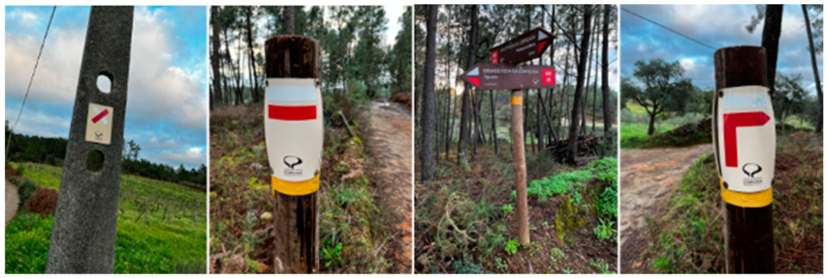
In recent years, hiking and cycling have gained prominence as two of the most popular activities for promoting physical activity, health and well-being. These activities consist of trails classified into three categories according to the distances involved: Long Routes (GRs), over 30 km long; Short Routes (PRs), less than 30 km long; and Local Routes (PLs), in which all or more than half of the route takes place in an urban environment [1]. Each of these trails is duly marked with signs, shown in Figure 1, along its way. These markings can be found in various places, such as rocks, walls, stakes and electricity pylons, among others [2]. Figure 2 illustrates some examples of the location of these markings.
Walking, hiking and cycling trails or routes are created and maintained by various entities, such as sports federations, mountaineering and camping associations, government entities at the national, regional or local level, as well as organizations linked to the tourism sector [3]. According to the Federation of Camping and Mountaineering of Portugal (FCM) [4], which is responsible for registering and homologating walking routes, there are 76 Short Routes and 46 Long Routes homologated in Portugal, according to the Regulation for the Homologation of Walking Routes (RHPP) [1]. This regulation establishes specific standards and criteria for the official recognition of a walking trail [5]. However, there are many trails managed by the FCM that are not registered in the National Register of Footpaths (RNPP).
Portugal has been committed to developing these trails to boost sustainable tourism and sports in nature. However, since these spaces are freely accessible, there is no information on how often they are used and by what type of users.
The most common solutions for collecting data on route use involve hiring human resources to carry out these surveys. However, hiring human resources is expensive and often inaccurate, as it is not possible to monitor all users who pass through the routes 24 h a day, 7 days a week. Another common way of collecting data is to indirectly ask route users to indicate that they have passed there and in what way, incentivizing them with some kind of reward [6].
Traditional counting methods are therefore inadequate. Technology-based data collection of users’ passages on routes can generate more accurate and valid estimates [7].
Considering that in most cases, municipalities are the driving force behind the infrastructure that supports cycling and walking routes, it is important to assess the tourist impact that these trails bring to the regions. Accurate and reliable data are therefore needed, based on reliable information that proves their use. Therefore, identifying the different types of users, counting them and knowing the peak times are essential information for the managers and promoters of these infrastructures. This information can also help assess the strategic importance of these facilities in tourism development, especially in areas with low population density. Another relevant aspect of the analysis of the data collected is the management of the capacity to use these infrastructures. Considering that along these routes, there are often sensitive areas with specific preservation regulations (e.g., natural parks, protected areas and special protection zones, among others), collecting data on the rate of use is extremely important in managing access to these areas. Therefore, there is a pressing need to implement a solution that enables data to be collected, processed and analyzed.
In a recent study by the same authors of this paper [8], a comprehensive state-of-the-art review was carried out for various projects, techniques and methods for detecting and counting different users of cycling and hiking trails and routes. Computer vision was identified as a suitable solution. A dataset was created and the performance of the convolutional neural network (CNN) models YOLOv3-Tiny [9], MobileNet-SSD V2 [10] and ResNet-50 [11], which were considered the most promising, was evaluated. It was concluded that YOLOv3-Tiny is the most promising model, given the accuracy recorded and the computing power required.
Following our previous study, this paper aims to propose, implement, test and validate a low-cost prototype demonstrator, based on the Internet of Things (IoT), computer vision and the concept of opportunistic networks, to meet this challenge. The prototype should work in the scenario illustrated in Figure 3, where it is assumed that cycling and hiking trails are used by a variety of pedestrian, cyclist and motorcyclist users, which we aim to identify and count.
It is assumed that a set of IoT devices, which will be responsible for detecting and counting the different types of users, will be strategically positioned along the trails, in places where there may not be an Internet connection (e.g., using a mobile network). These devices have non-volatile memory that can store the information on the user count for extended periods until an opportunity arises to propagate it [12]. This concept of opportunistic communication is defined by Delay Tolerant Networks (DTNs) [13,14] and can be applied to scenarios such as interplanetary networks, military and tactical systems, disaster recovery networks, vehicular communications and wildlife tracking/monitoring.
To make it possible to collect the data stored on these devices, it is assumed that some of the users of these trails will use a mobile application on their smartphone which, in addition to information about the routes, could for example provide indications about the wild flowers and plants that can be found along them, as described in [15,16]. When a user with the mobile application approaches one of these IoT devices, a contact opportunity arises, and user count information can be sent to the smartphone.
Later, when the user has Internet access on their smartphone, the data with the counts of the different types of users will be sent to a remote server. Once again, this process takes place automatically and transparently for the user. This information will then be aggregated, processed and made available to the managers of these infrastructures, for example via a web application.
The rest of this paper is organized as follows. Section 2 presents the prototype developed as part of this study. It describes and justifies the architecture adopted, the hardware and software components, and the implementation process. Section 3 describes the tests conducted to validate the prototype. Finally, Section 4 presents the conclusions of this study, highlighting the results obtained and discussing possible directions for future work.

2. Prototype

This section presents the prototype developed in the context of this study. The first subsection describes its architecture. The second and third subsections detail the process of implementing the prototype’s hardware and software.

2.1. Architecture

Figure 4 shows the architecture of the prototype system for detecting and counting different users of cycling and hiking trails and routes. This architecture responds to the scenario presented in Figure 3 described above. The architecture is centered on two main elements: the sensor node and the bridge node.
The sensor nodes are IoT devices that will be responsible for detecting and counting different types of users (people, bicycles, motorcycles). It is assumed that these nodes will be strategically positioned along the trails, in places where there is no conventional Internet connection, for example via a mobile network. They have a camera and storage and support Bluetooth communication. Following our previous work [8], it was decided that a YOLOv3-Tiny CNN [9] would be trained and run on these nodes using a dataset developed in the context of this study. This decision was made based on its prediction speed, processing requirements and accuracy.
These nodes will store the count information of different types of users in non-volatile memory for extended periods of time until an opportunity arises to propagate it. This concept of opportunistic communication that supports long communication delays is defined by DTNs [17,18], which are networks that aim to provide connectivity in scenarios where TCP/IP protocols simply do not work. These networks seek to take advantage of mobile devices that support wireless technologies to interconnect network partitions over time.
It is assumed that the sensor nodes support Bluetooth, which is a short-range wireless communication technology [19] that uses radio frequency (RF) operating between 2.4 GHz and 2.5 GHz to transmit data. When Bluetooth-enabled devices are in close proximity, they can detect each other and negotiate terms for pairing, and then exchange data. Generally, the closer they are, the better the connection [20]. While the Bluetooth 4.0 version supports indoor ranges of 10 m and outdoor ranges of 50 m, Bluetooth 5.0 allows for low-power transmission and can support indoor ranges of 40 m and outdoor ranges of up to 200 m. In terms of transmission speed, Bluetooth 5.0 is twice as fast as Bluetooth 4.0. While Bluetooth 4.0 reaches theoretical maximum speeds of up to 1 Mbps, Bluetooth 5.0 can reach up to 2 Mbps [21]. Bluetooth was chosen over Wi-Fi because it has much lower energy consumption [22,23], which is important in this scenario that assumes battery-operated devices.
The bridge nodes are intermediaries and play a fundamental role in propagating the data collected from the sensor nodes to the server on the Internet. It is assumed that the bridge nodes are the smartphones of some of the trail users, so they have non-volatile storage memory and Bluetooth.
When a user with the mobile application (i.e., bridge node) approaches a sensor node, the opportunity arises for a contact to send count data. The process of detecting, negotiating and establishing a Bluetooth connection between the sensor node and the bridge node is automatic. The same goes for sending the data stored in the sensor node to the bridge node, which cooperate in the task of accepting and storing it [12]. No human intervention is required in these processes.
This approach aims to exploit the fact that users will later use a mobile network or Wi-Fi to access the Internet. At that point, the data with the user counts are sent to a remote server, where they will be stored on a database server. This process may be subject to errors, for example in the user’s application, which could compromise the delivery of the data with the user counts to a remote server. Therefore, we opted for a strategy of replicating the information with the count data across several users, according to an approach known as Spray and Wait [24], which is appropriate for this scenario [25].
The data collected over time, according to this process, will be accessible via a web application which will generate statistical reports.
To implement this architecture, it is necessary to take into account various aspects that could hinder the development of the prototype that demonstrates this concept. Table 1 shows the challenges identified along with the hypotheses considered for developing the prototype. In the following sections, the proposed solutions for each of these challenges will be discussed and explained, considering the different hypotheses analyzed.

2.2. Hardware Component

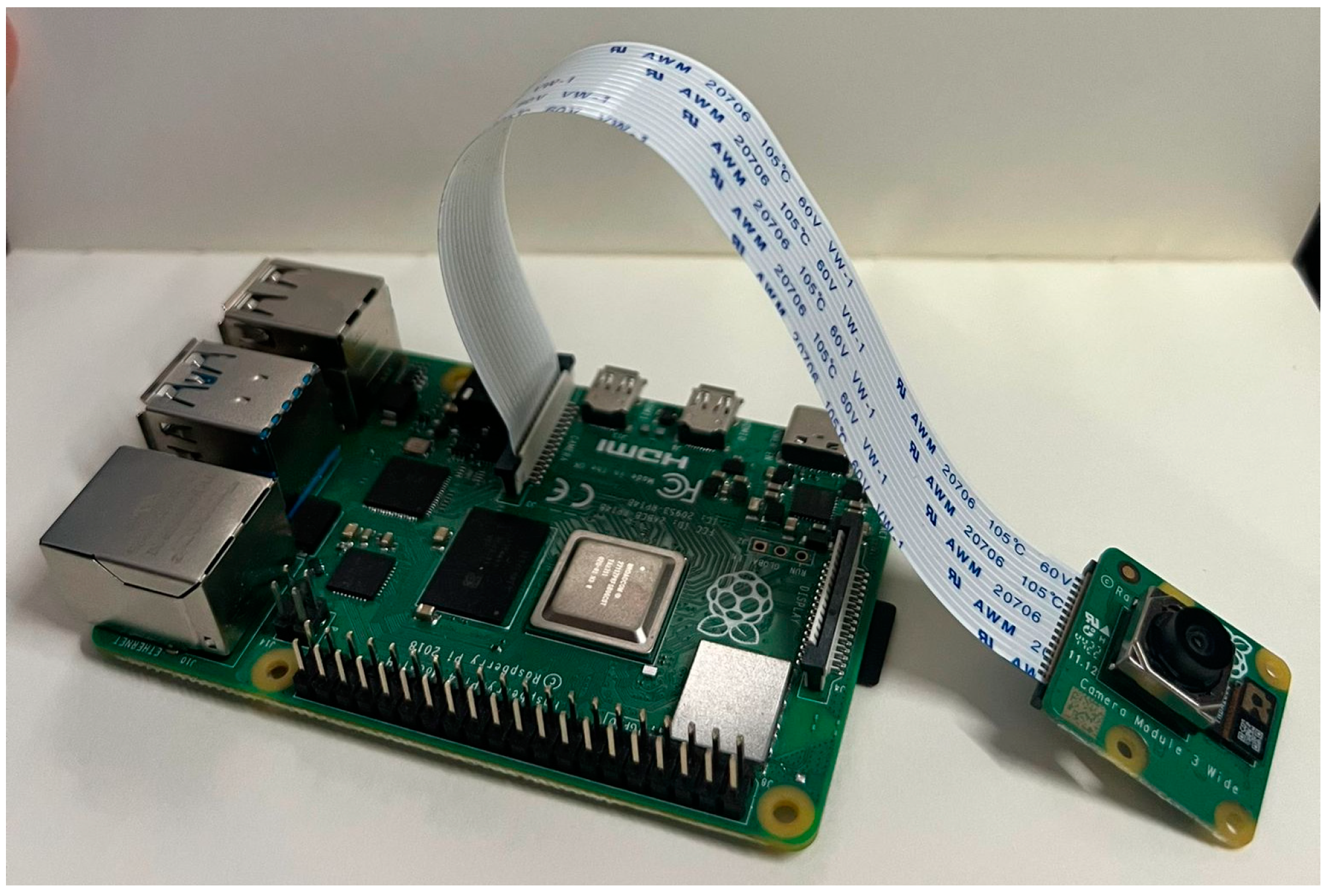
The following hardware was used to implement the prototype with the systems that make up the architecture described. The sensor node was implemented on a Raspberry Pi 4 Model B with 4 GB of RAM [26], with a 32 GB Micro-SD and Bluetooth 5.0 support. A Raspberry Pi Camera Module 3 [27] camera will be connected to this single-board computer via a ribbon cable, as shown in Figure 5.
The bridge nodes, responsible for communicating via Bluetooth with the sensor node to collect information and then send these data to a database hosted on a server on the Internet, are Android smartphones belonging to the users of the trails. They will have installed a mobile application described in a later section of this document.
The remote database and application server are hosted on a machine with an Intel-Core I7-11370H processor, 16 GB of RAM and an NVIDIA RTX 3050 graphics card.

2.3. Software Component

This subsection describes the development and implementation of the software needed to run the proposed system. The use of CNNs to detect and classify different types of users on cycling and hiking trails is discussed. Next, the role of the sensor node and the bridge node in the system is detailed, describing their functionalities. Next, the database and its entity–relationship model are presented, which stores the information collected from the sensory nodes, as well as the API that performs actions on the database, detailing the available operations and their integration with the other components of the system. Finally, the application server is presented, describing its functionalities, as well as the user interfaces developed for viewing and analyzing the data collected.

2.3.1. Convolutional Neural Networks

Most computer vision systems for real-time object recognition use convolutional neural networks [28], as they are considered particularly effective at extracting objects from an image, identifying relevant patterns and recognizing objects in context [29]. CNNs are deep learning networks, influenced by visual function and the structure of the visual cortex. They resemble the behavior of neurons in the human brain [30].
Figure 6 shows the structure of a convolutional neural network. It consists of convolutional, pooling and fully connected layers, each with a specific task in propagating the input image. The convolutional layers are responsible for extracting features from the previous layer or from the input image if this is the first layer of the network. The main function of the pooling layers is to smooth the information at the output of the convolutional layer [31], reduce the size of the data and help keep the representation consistent between smaller versions of the inputs. Finally, the fully connected layer controls signal propagation and applies point-to-point multiplication activation functions. The last layer produces the probability of a single input image belonging to the class for which the network was trained, based on the activation function used [32].
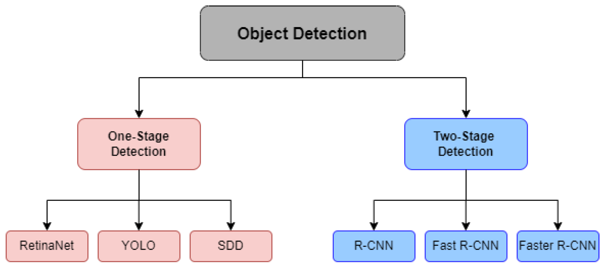
Object detection has two functions: object localization, which determines the location of the object, and object classification, which determines the class to which the object belongs. Finding the location of objects using CNNs is challenging due to differences in image perspectives, sizes, postures and lighting conditions [33]. The CNN models that can be used for these tasks fall into two types: one-stage detection and two-stage detection. In short, two-stage models tend to have high accuracy in object recognition [34], while one-stage models focus more on speed in performing this task [35]. Figure 7 shows three examples of models for each of these types.

One-Stage Detection

One-stage models, whose architecture is illustrated in Figure 8, perform two actions simultaneously: they identify specific characteristics in the images, such as shapes, colors and textures, and classify them according to what they represent (e.g., person, car, bicycle and dog, among others). Initially, the images are analyzed with a feature extractor that uses a CNN, and then, the extracted features are used directly with the bounding box coordinates and boundary regression [36].
Compared to two-stage models, these models are much faster and strike a balance between speed and detection accuracy [35]. Due to their speed, they can be used to constantly track objects.

Two-Stage Detection

Two-stage models solve the detection problem in two stages, as shown in Figure 9. The first stage involves creating a region of interest (ROI) and extracting features using CNNs. The second stage consists of inputting the features identified from the ROI into a classifier based on support vector machines (SVMs) or CNNs to classify the features and then correct the positions of the objects using bounding box regression [35].
In the previous study from the same authors of this paper, the performance of three different models was compared: YOLOv3-Tiny, MobileNet-SSD V2 and FasterRCNN with ResNet-50. The YOLOv3-Tiny model was identified as the most promising, as it had the best mean average precision (mAP) and the second highest frames per second (FPS) rate. This justifies choosing it for the development of the prototype presented in this paper.
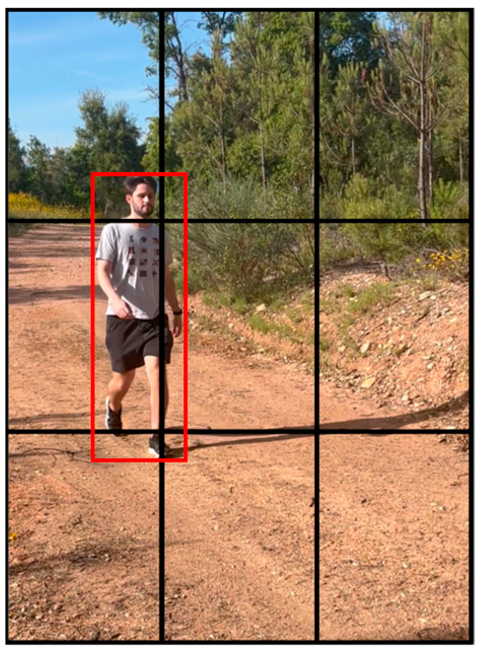
YOLOv3 [37] is a real-time one-stage object detection model. It therefore only processes the entire image once to find objects. This model divides the image into a 3 × 3 grid of cells and each cell checks whether or not there is an object nearby, as shown in Figure 10. In each cell, the model represents the location of the object in the image and indicates the probability and the class of the object, if applicable. This system offers excellent speed when the application requires efficiency [38].
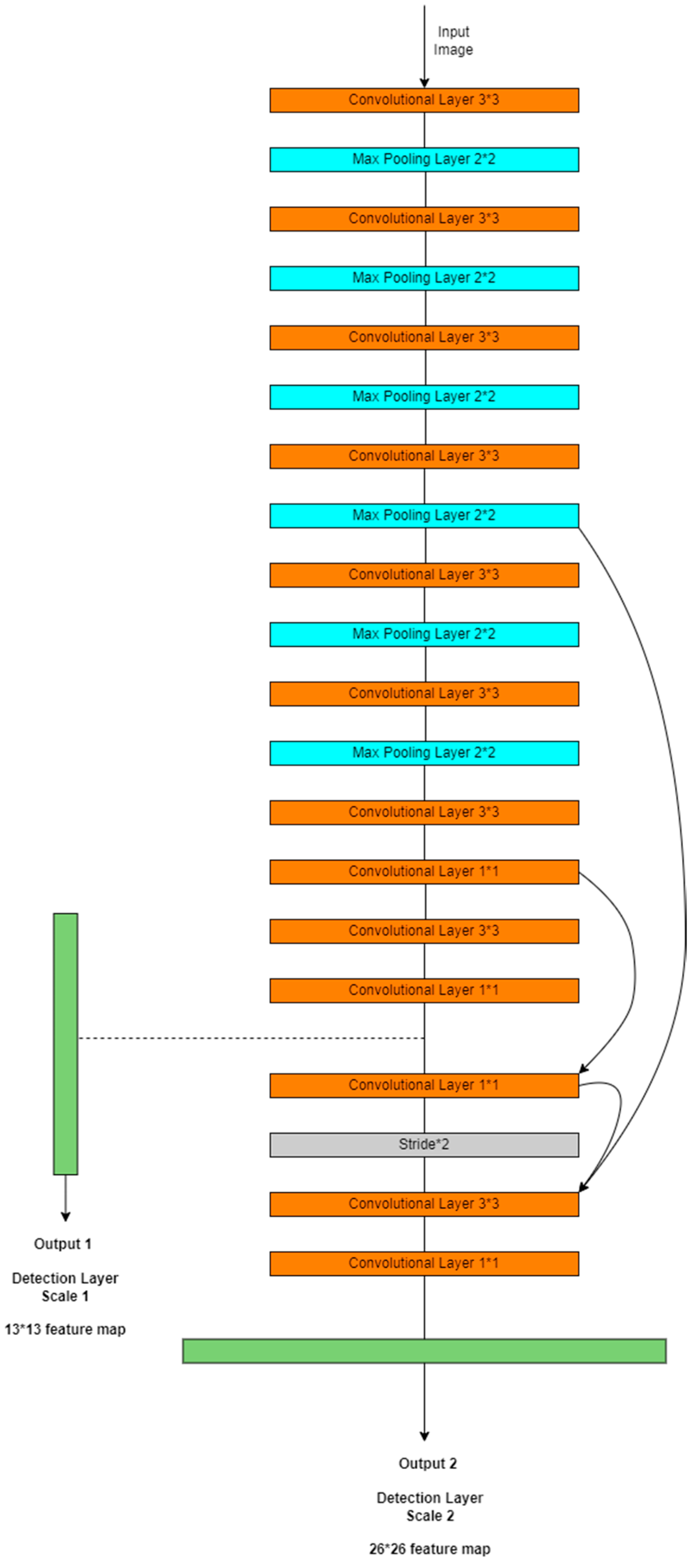
YOLOv3-Tiny [9] is a simplified version of YOLOv3 designed to consume fewer computing resources. It uses 13 convolutional layers, a significantly lower number than the 106 layers of the standard version (53 convolutional layers, added to the 53 layers of the Darknet-53 feature extractor used by YOLOv3). Since this architecture requires fewer filters, the size of the model and the training time end up being smaller [39]. The architecture of this model is shown in Figure 11. It is considered a good choice for applications that require high computational efficiency, such as mobile devices or embedded systems [40].
The dataset created in our previous work [8] showed a discrepancy in the number of images between the person class and the motorcycle and bicycle classes. The person class had the highest number of images. The dataset had a total of 440 images, divided between training, validation and testing. To solve this issue, more images were added to better represent the remaining classes. Thus, the new, improved version of the dataset has 1086 images, of which 761 are for training, 223 for validation and 102 for testing. This updated dataset is available for the community in [41]. The total number of images per set shown in Table 2 considers that some of the images contain identifications of several classes.
With regard to the number of bounding boxes present in all of the images in the dataset, it can be seen in Figure 12 that the person class has 946 identifications, the bicycle class has 517 identifications and the motorcycle class has 566 identifications.
The same benchmark scenario as in [8] was used to train the new YOLOv3-Tiny model. A Google Colab notebook [42] created by Roboflow [43] and later adapted [44] was used. The NVIDIA Cuda Compiler Driver [45] was installed to associate the graphics processing unit (GPU) with the run, as well as the Darknet framework [46]. The YOLOv3-Tiny base weights were downloaded in YOLO Darknet format and, with the help of the Roboflow library for Python, the dataset was downloaded and prepared. The images and their labels were organized in the correct directories and the training configuration file was adjusted, setting the number of epochs at 6000, according to the recommendations of the Darknet repository [47]. Finally, training began with the specific Darknet command, which lasted a total of 2 h and 30 min. The training process was executed a single time. During the training process, the CNN learns to recognize patterns and features that are characteristic of the different types of users.
The mean average precision (mAP) metric was used to assess performance. This evaluates the effectiveness of the model in detection and classification by calculating the average precision (AP) of each class, allowing for an effective comparison between models [48]. Loss represents the collective error in the model’s predictions, calculating what it predicted and what should have been predicted [49]. This metric is used during training.
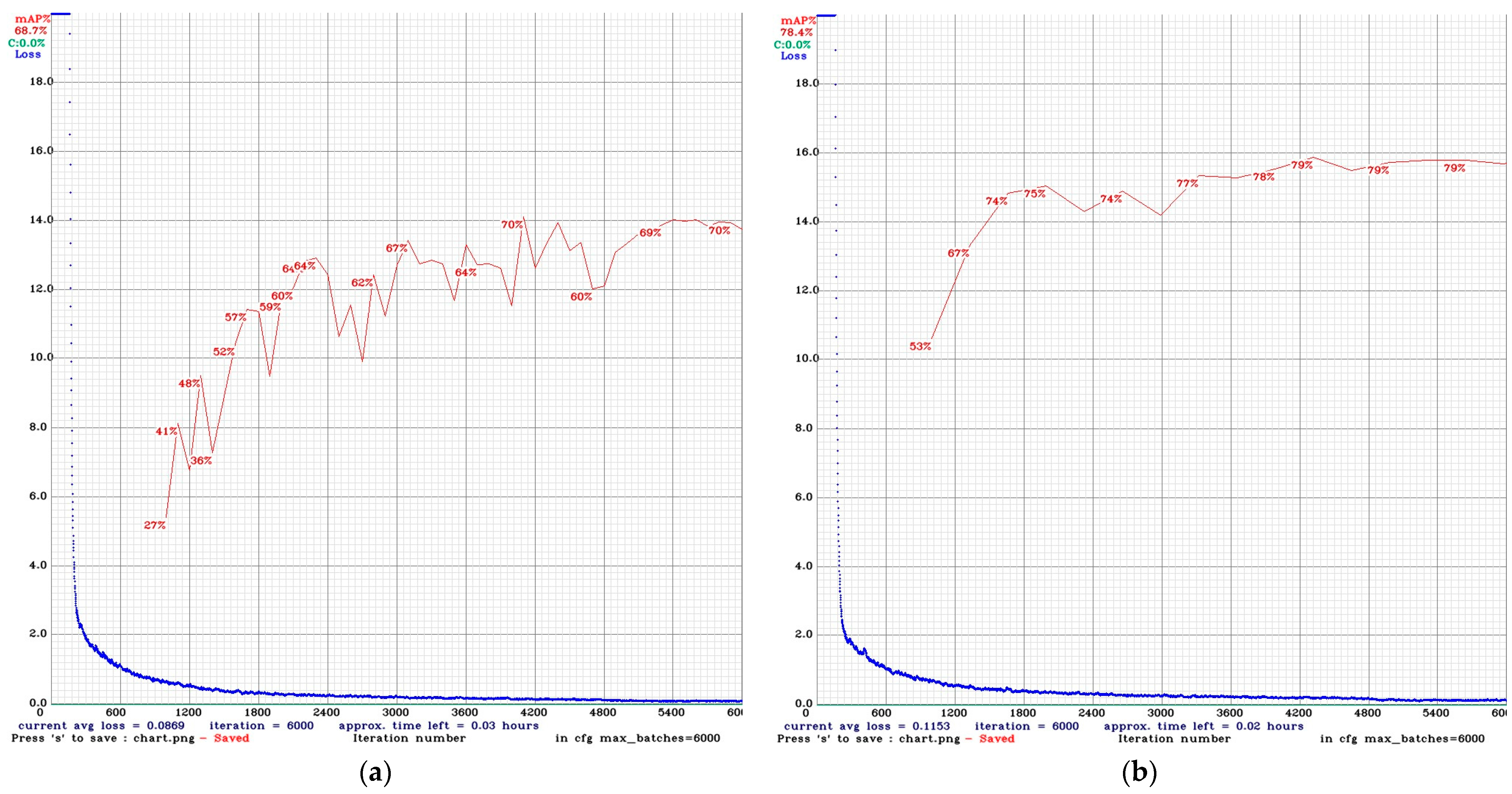
Training the new YOLOv3-Tiny model took a total of 1 h and 28 min. In each iteration, a graph was generated as shown in Figure 13b, where the mAP values are highlighted in red, while the loss values are highlighted in blue.
Comparing the training graphs shown in Figure 13 of the new model (b) and the previous one (a), it can be seen that the evolution of mAP was more linear, showing a constant growth until epoch number 4300. The final mAP value reached 78.4%, representing an increase of 9.7%, which translates into a substantial improvement in detection capacity. The model with the best mean average precision score on the validation set was used for testing. In addition, the graph shows an exponential reduction in loss, initially sharp and then stabilizing at values close to 0.1.

2.3.2. Sensor Node

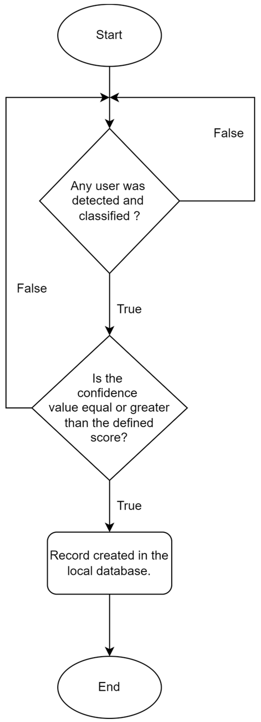
The operating system running on the sensor node is Raspberry Pi OS (Legacy, 64-bit) Lite [50]. Two scripts are run there simultaneously: one for detecting and classifying the different types of users on the trails, adding these records to the local database, and the other for connecting and transmitting the data to the bridge node. The detection and classification script, described in Figure 14, runs the CNN model previously trained with YOLOv3-Tiny. If the model detects a user type, it only adds it to the local database (shown in Figure 15) if it is detected with a confidence value equal to or greater than the value indicated in the script execution command. This value was determined at 0.7 (70%) after a visual analysis of the detections made by the model at different confidence values. This approach helped identify a balance point where the model accurately detects users without generating too many false positives.
It is important to note that no images are stored in the database shown in Figure 15. Only information that classifies the type of user passing through the site is recorded, so as not to compromise privacy.
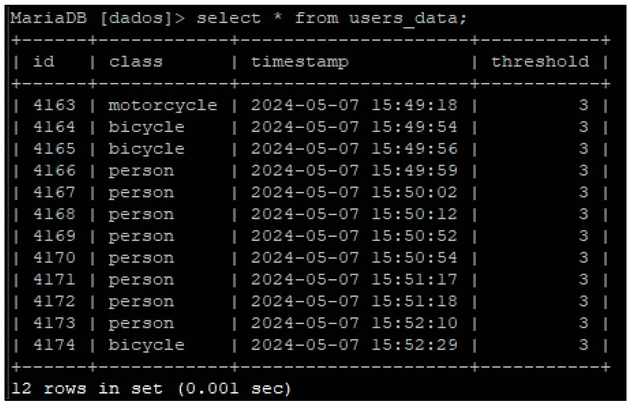
The local database implemented in the sensor node, using the MariaDB database management system (DBMS) [51], is made up of two entities. The Users_data entity is responsible for storing records relating to the detection of user types. The id attribute identifies the record. The class attribute identifies the class of the user type. The timestamp records the moment the user was detected and classified. The threshold is used as a control mechanism (see Table 1, A1). Its default value is 3 for each newly created record and it is decremented each time the record with this information is successfully transmitted to a bridge node. With this approach, it is guaranteed that each record with a specific user count will be transmitted to three different bridge nodes before being removed from the local database. To do this, the Threshold_Mac entity was created, which helps with this control by storing the MAC addresses assigned to the bridge nodes’ Bluetooth cards to which a given record has been transmitted. This approach is especially important to guarantee the delivery of the user count information stored in the sensor nodes to the remote database server available on the Internet. Furthermore, given the storage limitations of the sensor node, by setting a transmission limit for a limited number of bridge nodes, this makes it possible to effectively manage the storage available on Raspberry Pi.
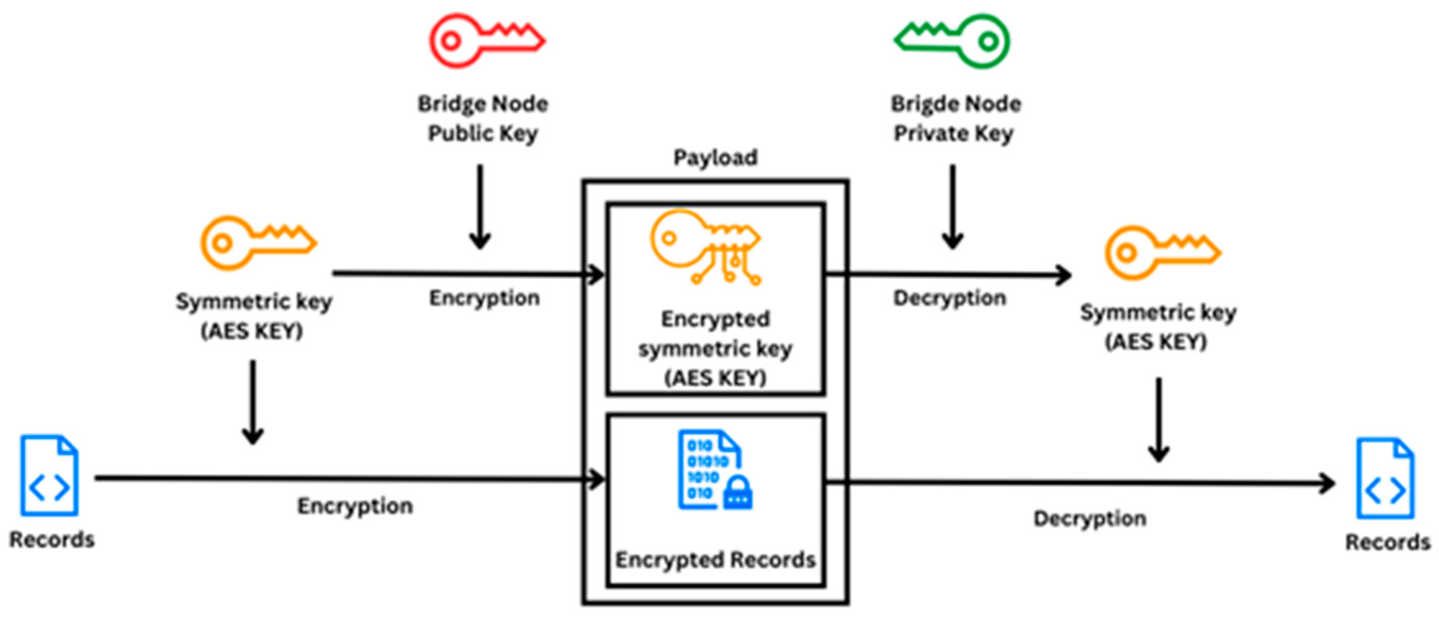
A data exchange system called a “hybrid cryptosystem” was used to establish the connection and transmit the data [52]. This system combines the advantages of symmetric and asymmetric cryptography to ensure both efficiency and security in communication. Initially, each node creates a pair of RSA-2048-bit asymmetric keys [53] and exchanges their public keys. Each time a node sends data, a new symmetric key (AES-256 bits [54]) is generated and encrypted with the recipient node’s RSA public key. The data are encrypted with the symmetric key. The sending node sends the encrypted data along with the encrypted symmetric key. When this message is received, the receiving node decrypts the symmetric key with its private RSA key. Finally, it decrypts the data with the symmetric key. This process is shown in Figure 16.
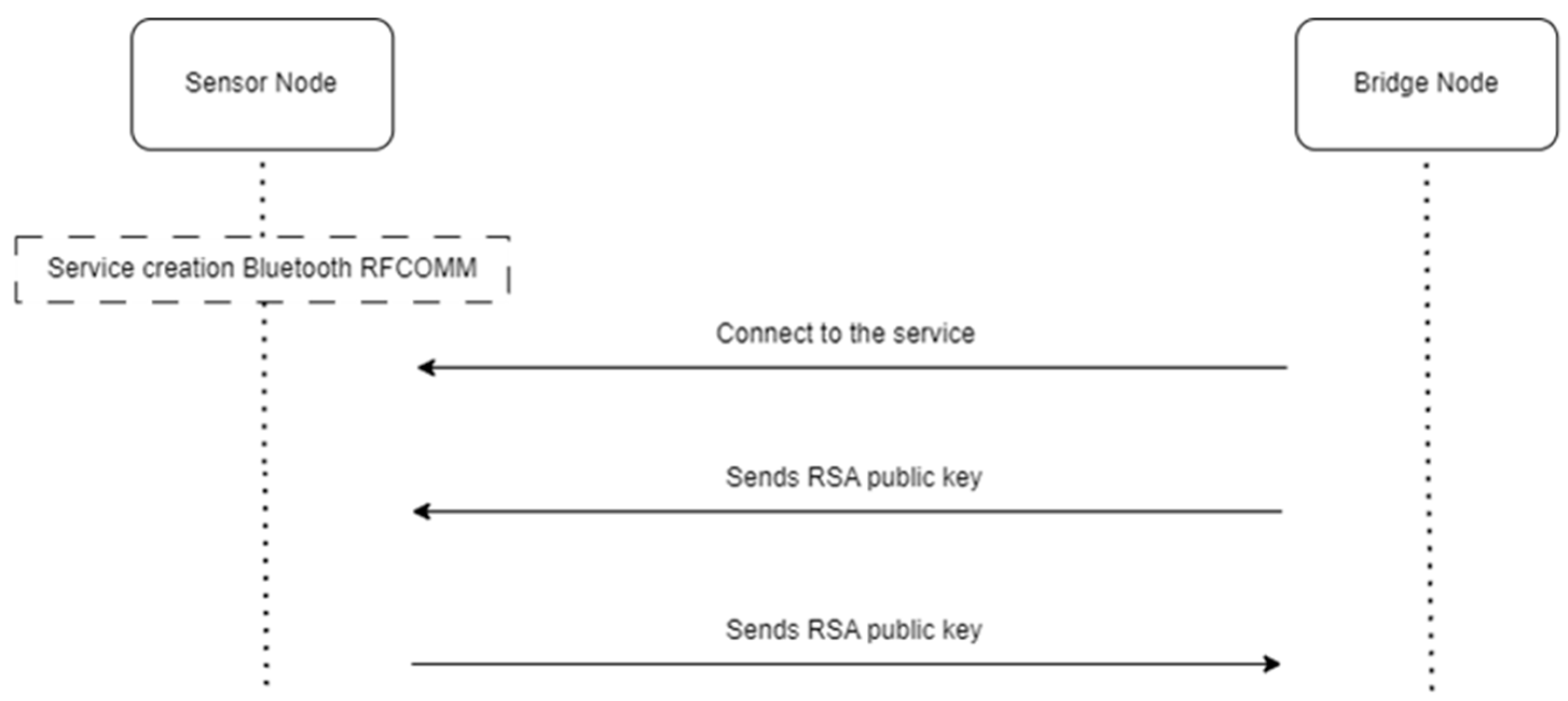
This approach offers both the efficiency of symmetric encryption and the additional security of asymmetric encryption [55] (see Table 1, A2). Initially, the mobile application running on the bridge node establishes a connection with the service provided by the sensor node. This connection is made via the RFCOMM protocol [56], which allows for serial communication over Bluetooth between the devices [57]. Both nodes generate a pair of 2048-bit RSA asymmetric keys (public and private) the first time they are started, and the public keys of each are sent to the peer node. This process is illustrated in Figure 17.
The bridge node continuously checks that it remains connected to the sensor node. At all stages of data exchange communication, a timeout of 2 s is set to prevent a node from being blocked at a certain stage of the process. Thus, if the communication is not completed within a certain period, the connection is terminated.
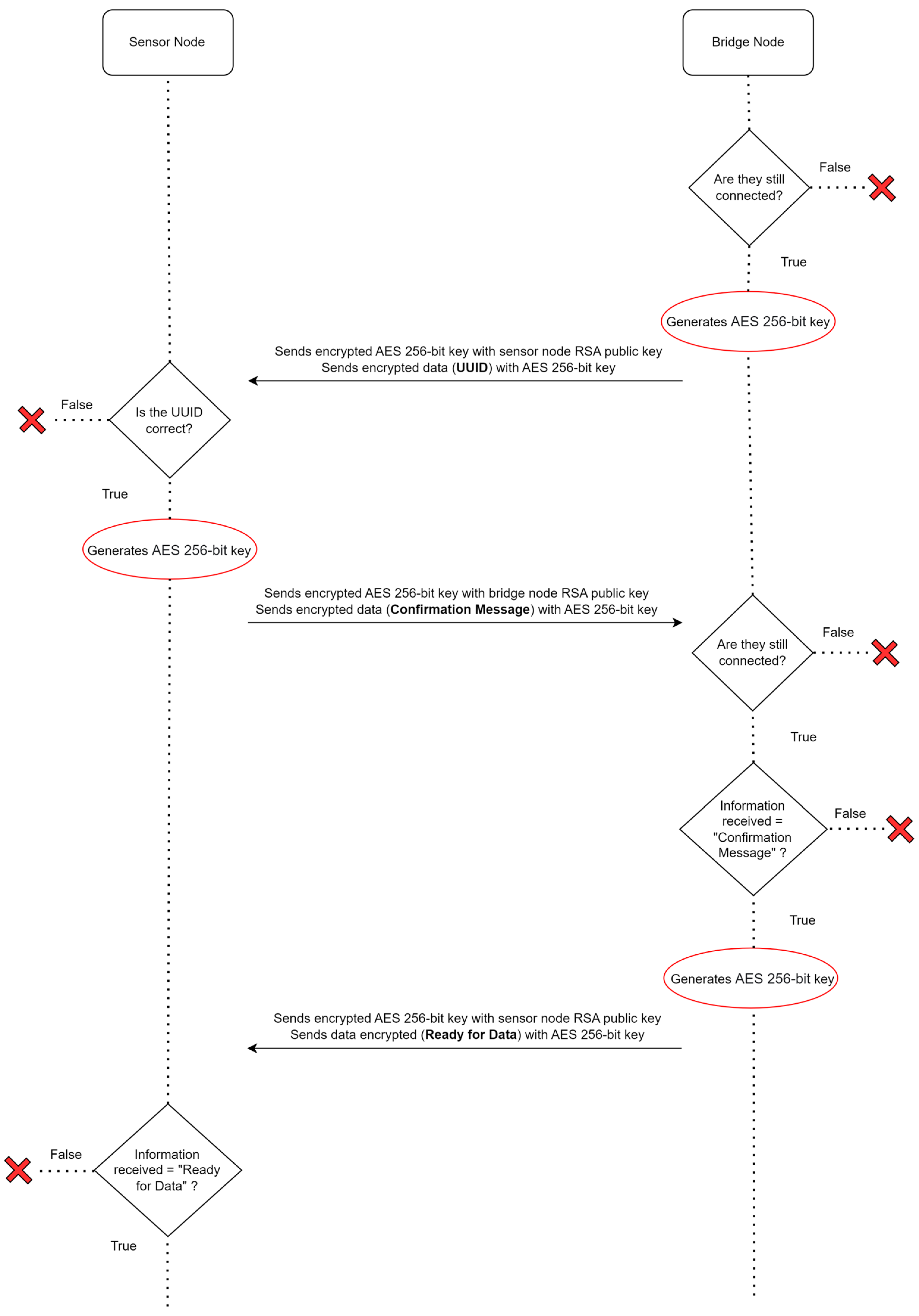
Continuing the authentication process, the bridge node sends the universally unique identifier (UUID) [58] to the sensor node, which then checks it to continue communication or terminate it if the UUID is incorrect. If communication continues, the sensor node sends a confirmation message to the bridge node. The bridge node confirms that the confirmation message is correct and, if it is, sends a message to the sensor node informing it that it is ready to receive data. Figure 18 describes this initial preparation before the data are transmitted.
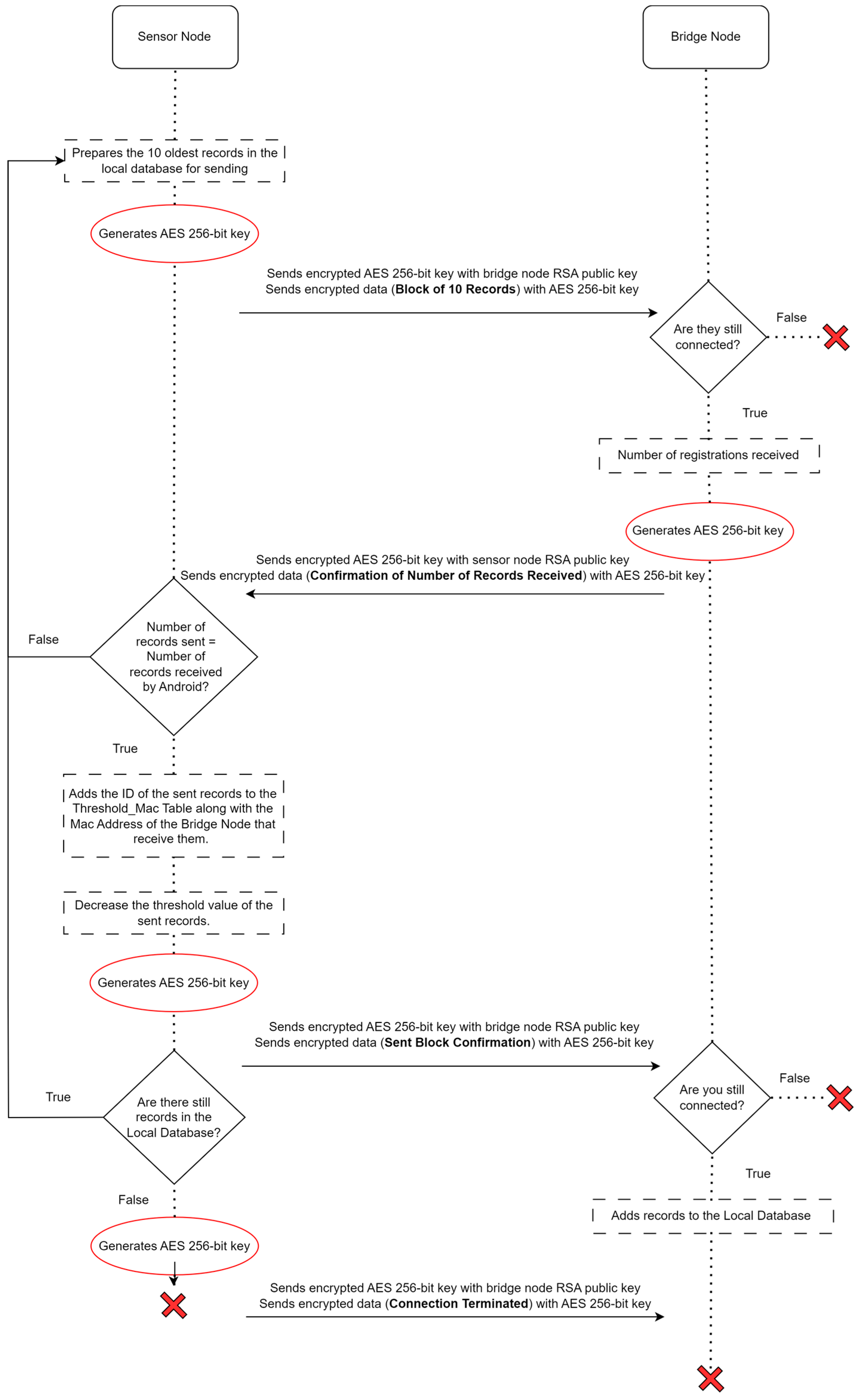
Then, the sensor node confirms that the bridge node is ready to receive the data. If it is, the sensor node starts sending the data in a cycle. In other words, the data are transmitted in blocks of 10 records, from the oldest to the most recent, to the bridge node. Instead of sending all of the user count records (i.e., data) at once, the records are transmitted in smaller blocks, significantly reducing the likelihood of failures (i.e., contact duration).
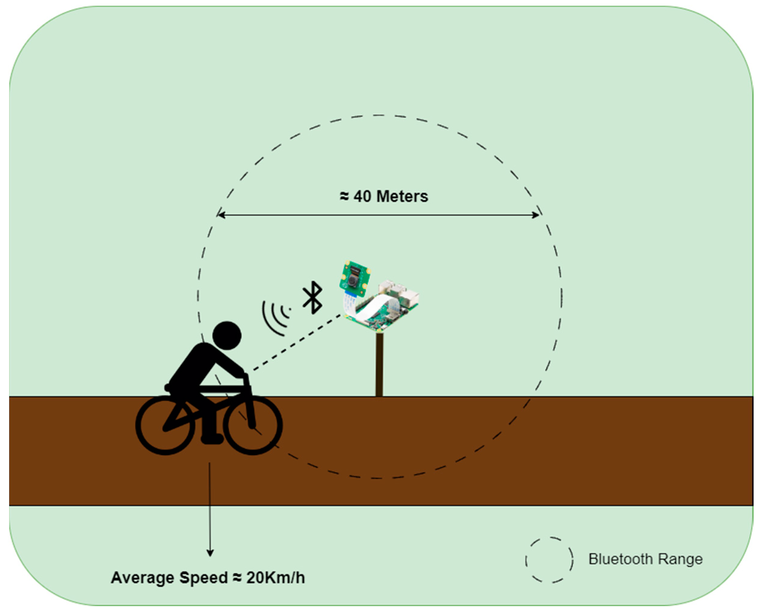
If a transmission error occurs, only the blocks of records that were not successfully transmitted will be resent (see Table 1, A5). To determine the optimum number of records to transmit per block, the contact time between a sensor node and a user moving on a bicycle was calculated. Considering that a bicycle passes the sensor node at an average speed of 20 km/h and that the Bluetooth range of the sensor node is around 40 m, as shown in Figure 19, the contact time would be approximately 7.27 s. Users who travel by motorcycle cannot be used as a bridge node due to their high moving speed, which potentially does not allow them to negotiate the connection and exchange data successfully (see Table 1, A3).
From this estimated contact time of 7.27 s, a period of 2.56 s is deducted for setting up the Bluetooth connection. This value was determined after carrying out 10 tests in environments with and without obstacles, within a radius of 20 m around Raspberry Pi. This leaves a useful contact time of 4.71 s for data exchange. Equation (1) illustrates how this time was calculated.
U s e f u l   C o n t a c t   T i m e   ( s ) = D i s t a n c e   ( m ) V e l o c i t y   ( m / s ) S e t u p   t i m e   C o n n e c t i o n   ( s )
The transmission rate of Bluetooth 5.0 is assumed to be 1.3 Mbits/s. It is known that a block contains 10 records plus the encrypted AES key. Therefore, this message will have a maximum of 642 bytes (equivalent to 5136 Kbits). This conversion is represented by Equation (2).
k i l o b i t s = b y t e s × 8 1000
This value was determined by taking the largest possible size for the block of 10 records plus the size of the AES key. The id attribute is not transmitted to the bridge node. The class with the most characters is “motorcycle”, so it can be up to 10 characters long. The timestamp attribute has 19 characters in the format provided (e.g., “1 May 2024 10:00:00”). The records are sent in JavaScript Object Notation (JSON) format [59], as shown in Figure 20. Thus, the following are required:
  • Two bytes for “square brackets” for the record array;
  • Twenty bytes for “curly braces”, delimiting each record;
  • Nineteen bytes for the “commas” separating the name/value array and separating the records;
  • Thirty-nine bytes of “spaces” between name/value, between name/value sets and between records (after the comma separating the records);
  • Fifty bytes for the name of the class attribute of the 10 records;
  • One-hundred bytes for the value of the class attribute of the 10 records;
  • Ninety bytes for the name of the timestamp attribute of the 10 records;
  • One-hundred and ninety bytes for the value of the timestamp attribute of the 10 records;
  • Eighty bytes for the “quotation marks” that are placed in the names and values of the 10 records;
  • Twenty bytes for the “colon” to separate the names from the values of the 10 records;
  • Thirty-two bytes for the AES-256-bit symmetric key.
Thus, up to 253 blocks of 10 records can be transferred per second, as shown in Equation (3), giving a total of 2530 records per second. Therefore, during the 4.71 s of useful contact, it would be possible to transmit up to 1191 blocks of 10 records.
R e c o r d s   p e r   s e c o n d = T r a n s f e r   r a t e   ( K b i t s ) M a x i m u m   m e s s a g e   s i z e   ( K b i t s ) × 10
After sending a block of 10 records, the bridge node informs the sensor node of the number of records it has received. If the number of records received by the bridge node is not equal to the number of records sent by the sensor node, the entire block of records is retransmitted. Otherwise, the transmission has been successful, so the threshold attribute of each record in the sensor node’s local database is decremented by one. As explained above, this approach limits the unnecessary replicated sending of data to the network. The bridge node adds these data to its local database.
This process of sending in blocks of 10 records is repeated until all of the data available on the sensor node have been transmitted, or the connectivity time window between nodes has ended. Once all of the data have been transmitted, the sensor node informs the bridge node and terminates the connection. Figure 21 describes this process.

2.3.3. Bridge Node

For the bridge node, a mobile application was developed in Java [60], using the Android Studio integrated development environment (IDE) [61]. It is important to note that the application requires a minimum version of the Android software development kit (SDK) (minSdk) of 30, which corresponds to Android version 11, to work correctly on the devices. The version of the Android SDK on which the application was compiled and tested (targetSdk) is 34, i.e., Android 14 (see Table 1, A3).
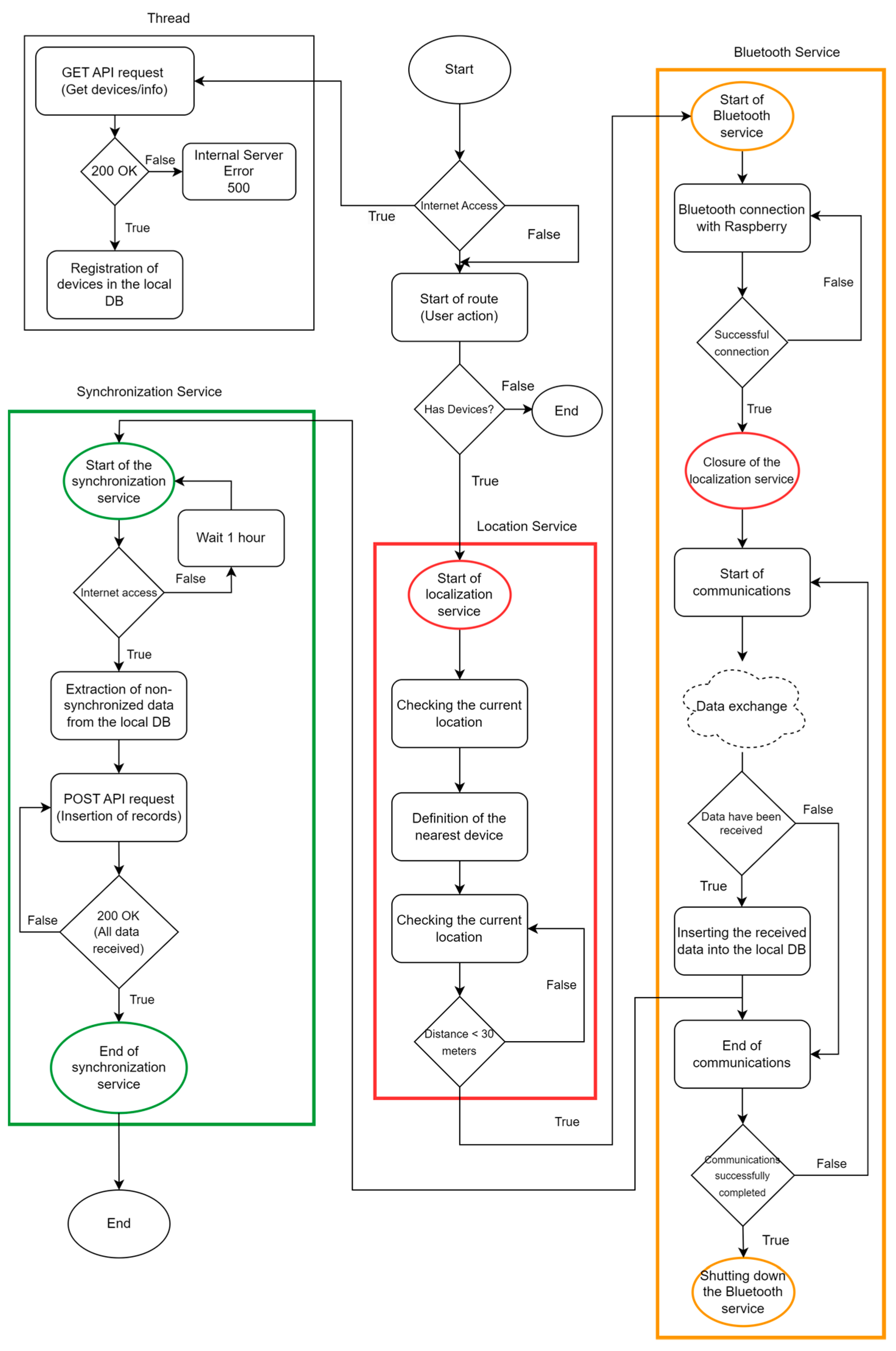
Because the goal is simply to demonstrate the concept, the application is simple and has been divided into three services [62]: location service, Bluetooth service and synchronization service. The application contains just one activity [63] with two buttons, as can be seen in Figure 22. One of the buttons starts the activity on the trail and the other ends it. This activity also contains a map with markers [64] which identify where the sensor nodes are located. In addition, a text area is displayed at the bottom of the graphical user interface (GUI), describing all of the actions carried out in the application, which is useful for functional tests and troubleshooting.
After initializing the application, if Internet access is available, the application makes a GET request to the API to obtain the GPS geographic coordinates of the available sensor nodes. If the request to the API is successful, the data received are stored in the application’s local database. Otherwise, an error will be displayed to the user. Once this information has been obtained, the locations of the sensor nodes are loaded onto the available map.
When the user presses the “Initiate Route” button, the application starts the location service, showing the smartphone’s current location (i.e., bridge node). Then, it determines the nearest sensor node, keeping it in memory. This service will be active even if the application is minimized (see Table 1, A4), so that it is possible to check whether the bridge node is at a distance of 30 m or less from a sensor node. Until this condition is verified, the service is “listening” until it reaches this distance. At this point, the Bluetooth service is started and tries to establish a connection between the sensor node and the bridge node. If this is unsuccessful, another attempt is made. Figure 23 shows the information that appears in the text area of the prototype mobile application when these iterations take place.
If the connection attempt is successful, the location service is terminated. The data are exchanged between the sensor and bridge nodes, as described in Section 2.3.2. Once the data have been received, the records are inserted into the bridge node’s local database. These steps can be seen in Figure 24, which shows the text area of the prototype mobile application.
The bridge node’s local database, shown in Figure 25, was implemented in SQL Lite [65] and consists of two tables: Users_data and Equipment. The Users_data table stores the records captured and stored by the sensor node and sent to the bridge node. Its attributes are id, which identifies the record uniquely, class, which identifies the class of the user type, timestamp, which indicates the date and time of the record, deviceId, which identifies the device that captured the record, and isSynced, which controls the synchronization of that record. The Equipment table stores data on the sensor nodes installed on trails that are available for data exchange. This table contains as attributes the id which uniquely identifies a sensor node, the name which serves to store its name, the latitude and longitude which together store the coordinates of its location, and the macAddress which stores the physical address of the Bluetooth communication card of that sensor node.
Once the information has been sent from the sensor node to the bridge node, communications are terminated. If unsuccessful, a new connection attempt is made. Otherwise, the bridge node’s Bluetooth service is terminated.
Afterwards, the synchronization service starts, which sends the records stored on the bridge node to the central database server, available on the Internet, via an API. This service runs in the background, even if the application is closed and removed from memory (see Table 1, A4). It is therefore assumed that the bridge node will connect to the Internet over time. If this connection is not available, a 1 h timer is used to continue trying to connect. When the Internet connection is finally detected, the data are extracted from the bridge node’s database and converted into JSON format and a POST request is made to the central API to insert the data into the central database. If this process is completed successfully, this service is terminated, as illustrated in Figure 26. If the response from the API is not 200 OK, a new POST request is made. Figure 27 describes this entire process.

2.3.4. Central Database

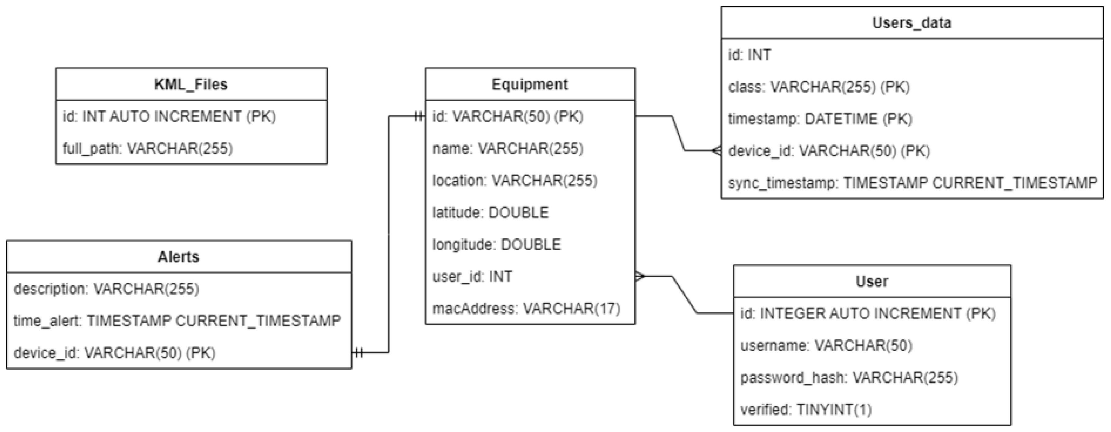
The central database was implemented in MySQL [66] on a machine running the Ubuntu 20.04 LTS operating system [67]. It adopts a relational architecture and contains five tables: KML_Files, Alerts, Equipment, Users_data and User. The purpose of the KML_Files table is to store the path of Keyhole Markup Language (KML) files [68]. These files are used to display geographical data on a map [69], such as Google Earth or Google Maps. These files are used to draw cycling and hiking trails on the web application map described in Section 2.3.5. This table has the following fields as attributes: id, which uniquely identifies a file, and the full_path attribute, which represents the path where the file is stored. These files are stored in a public folder on Drive, because a KML file must be accessed via a publicly accessible server on the Internet [70,71,72].
The Alerts table stores the alerts generated by the system. These alerts are triggered by a lack of data synchronization with the central database for more than 10 days. Its attributes are description, which represents a brief description of the alert, time_alert, which stores the date and time the alert was generated, and finally device_id, which stores the id of the sensor node to which the alert is associated.
The Equipment table is very similar to the table with the same name described in Section 2.3.3, except for two additional attributes: user_id, which keeps track of which user the sensor node belongs to, and location, which indicates in full the nearest location where that same node is located. The Users_data table is also similar to the table described in Section 2.3.3, but instead of having the isSynced control attribute, it uses the sync_timstamp attribute, which records the date and time of synchronization with the central database. Finally, the Users table stores the session data of the users who access the web application. It has four attributes: the id which uniquely identifies a user, the username which stores the username, the password_hash which stores the user’s encrypted password, and the verified which serves as access control. Figure 28 shows the entity–relationship model of this database.
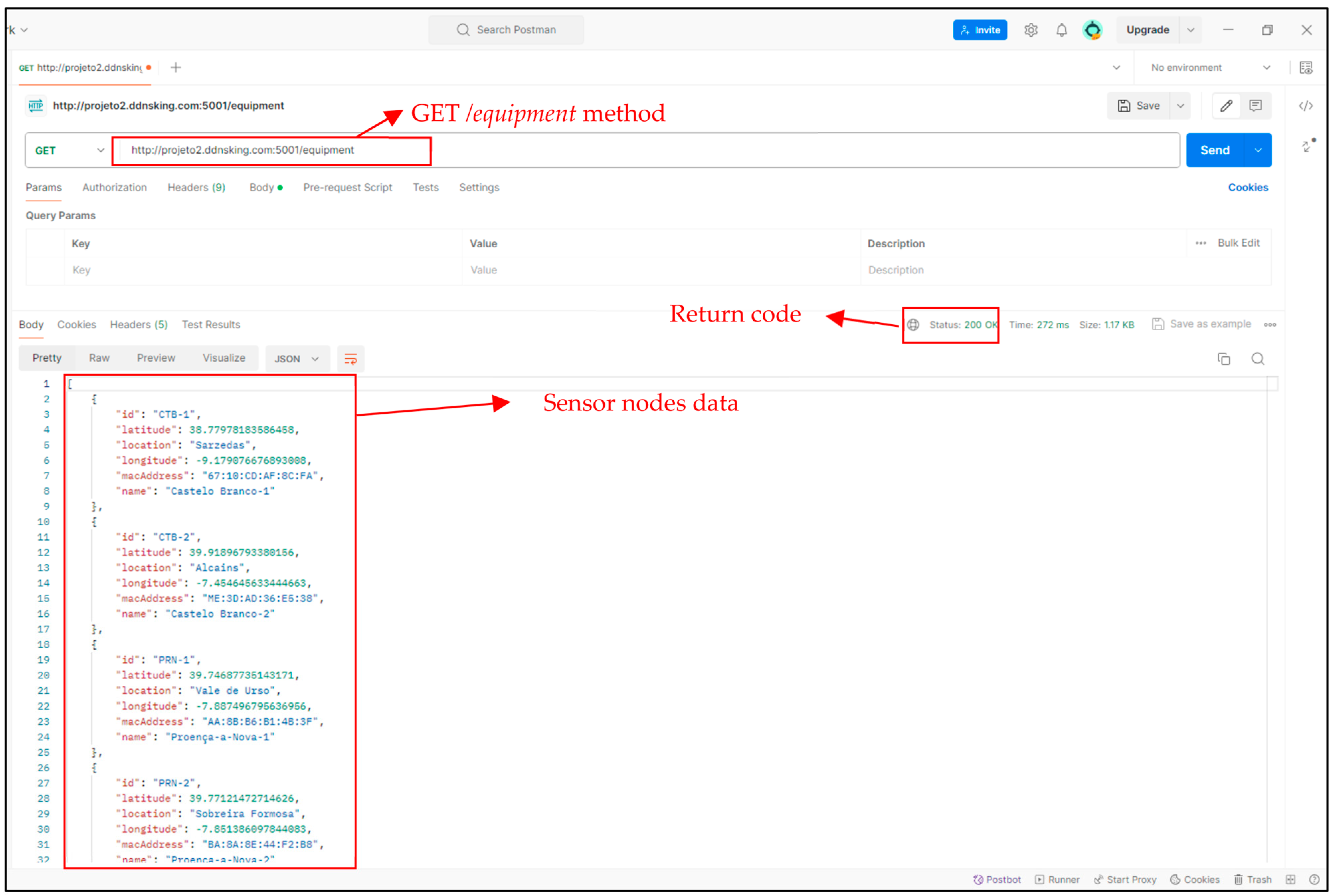
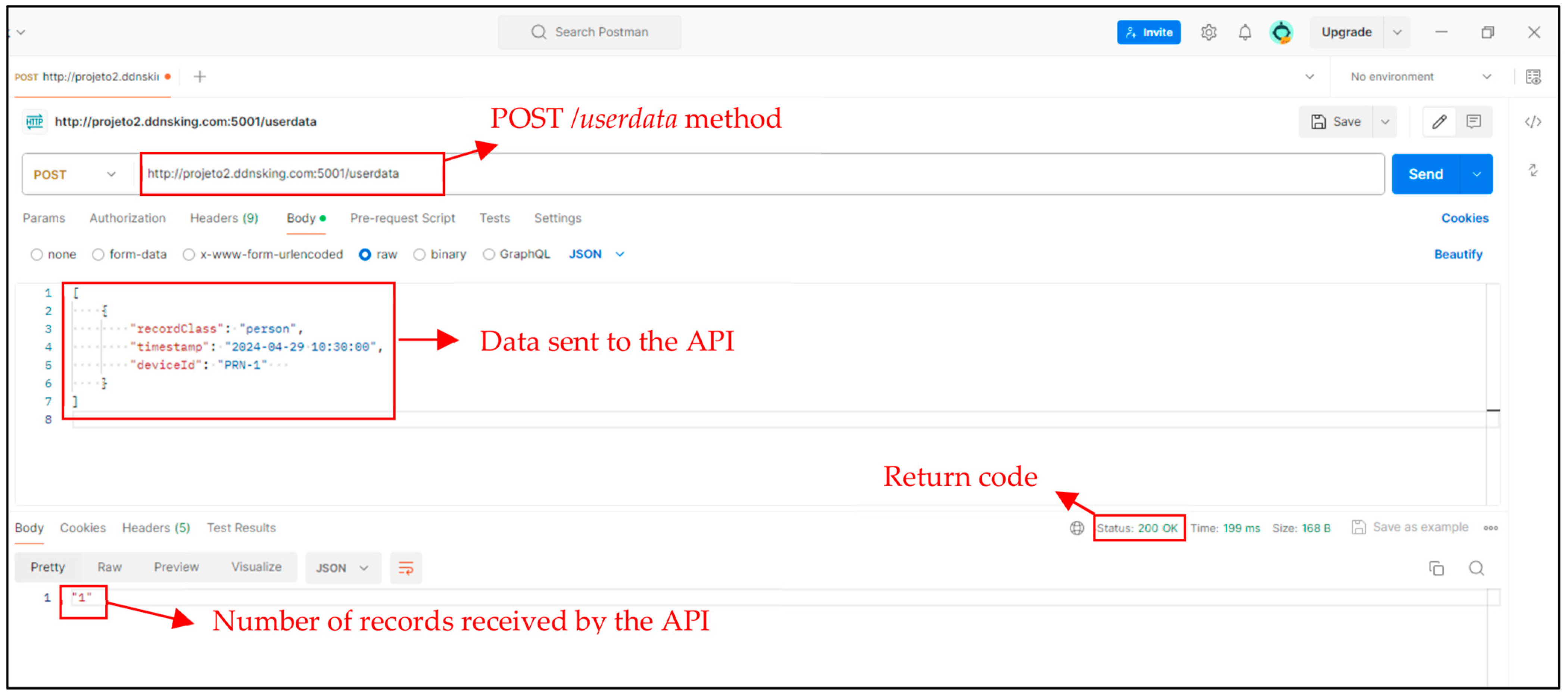
To interact with the central database, a Rest API was created with the Python Flask RESTful library [73]. Only two methods were created: a GET/equipment method to obtain the information from the sensor nodes registered in the central database, shown in Figure 29, and a POST/userdata method to send the records from the bridge node to the central database, to which the API returns the number of records received, as shown in Figure 30.

2.3.5. Application Server

The data captured by the sensor nodes over time and routed through the bridge nodes, according to the process described above, will eventually reach the central database. Then, they will be accessible via a web application that generates statistical reports available to infrastructure managers.
The web application follows a Model–View–Controller (MVC) architecture [74] and was also created using the Flask framework [75]. To use the web application, you must first register. After that, simply log in via the page shown in Figure 31.
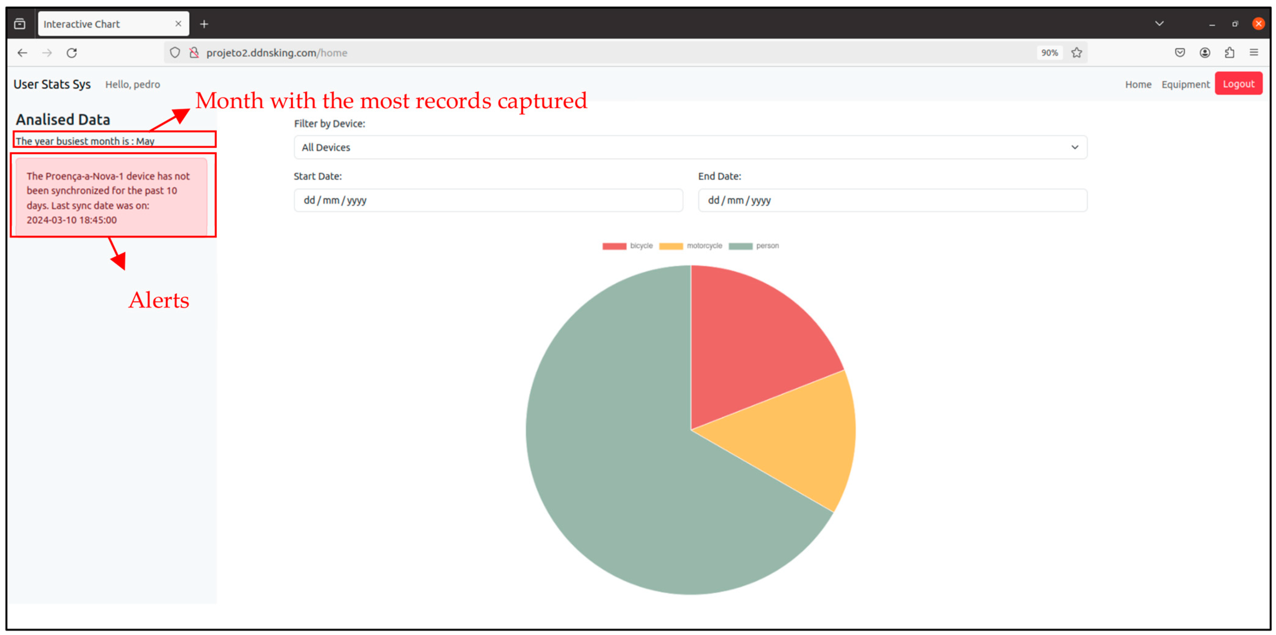
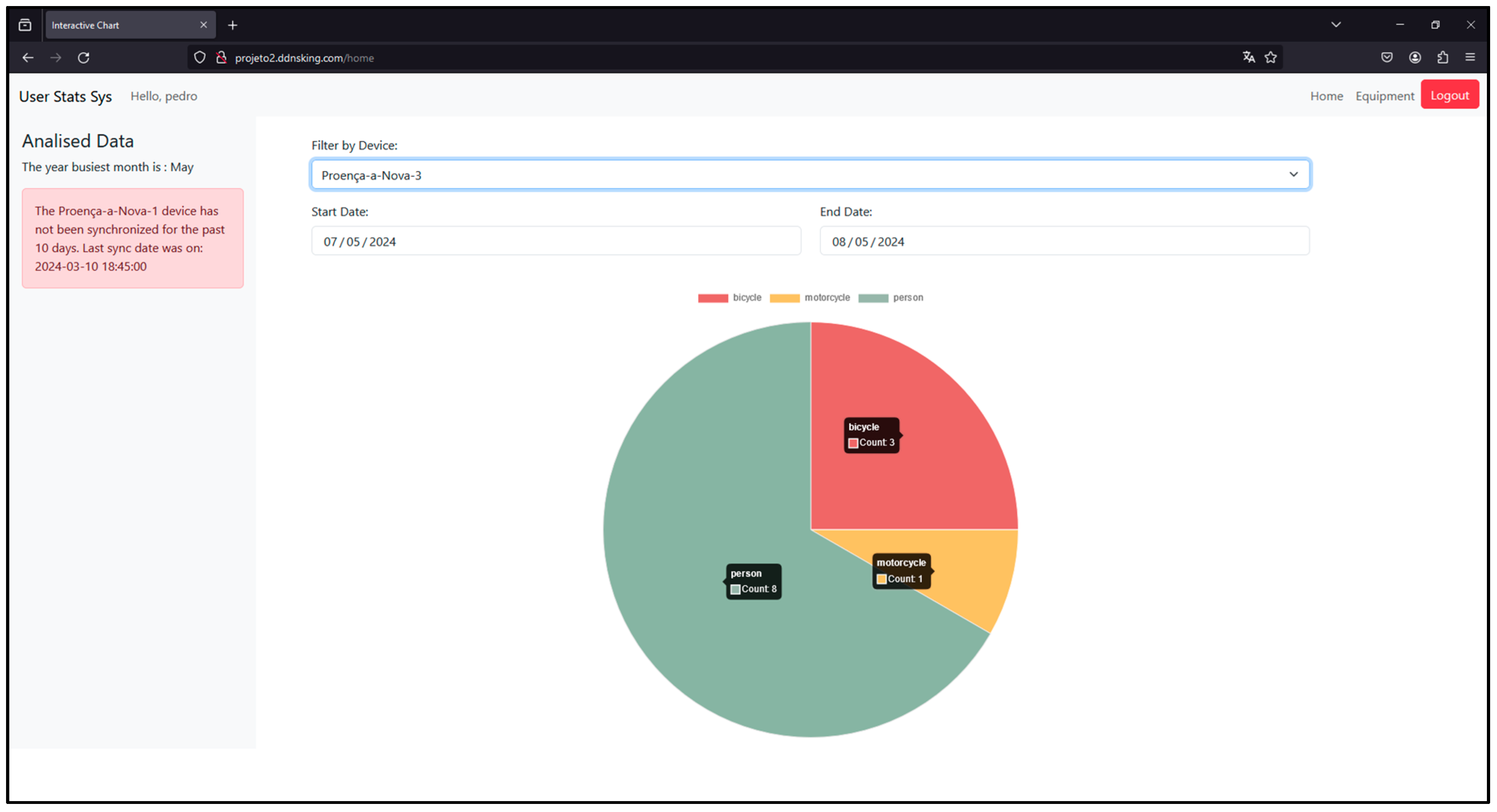
After successfully logging in, users are directed to the main page. There, users can apply filters by sensor node. In addition, it is also possible to apply date filters to view records captured within a specific period. Figure 32 shows this page. On the left-hand side, users can see the month of the current year with the most records captured. In addition, they can view the alerts associated with the sensor nodes they manage. These alerts are displayed when those nodes have not synchronized records for more than 10 days.
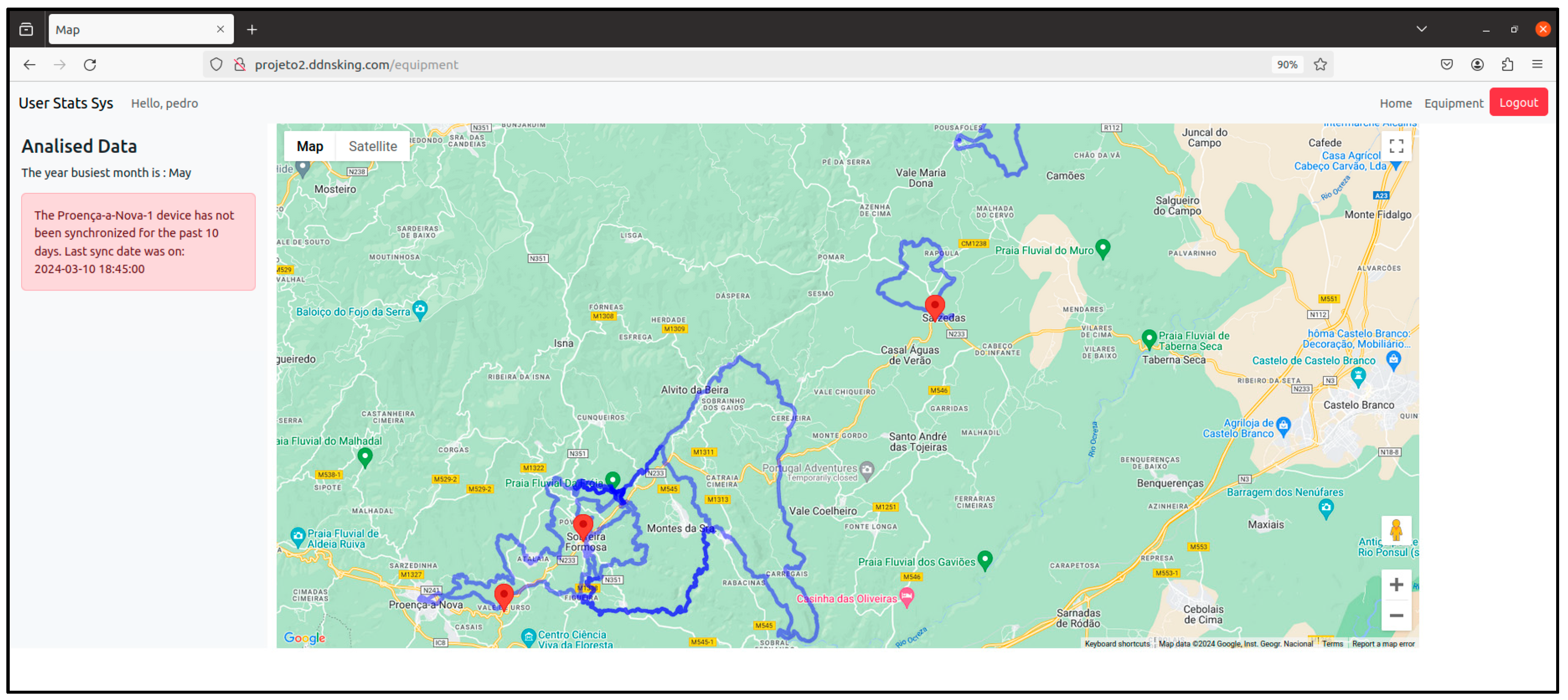
A page was also developed to represent the sensor nodes and trails stored in the central database on a map. This can be seen in Figure 33. The map used is Google Maps and was implemented via JavaScript [76].
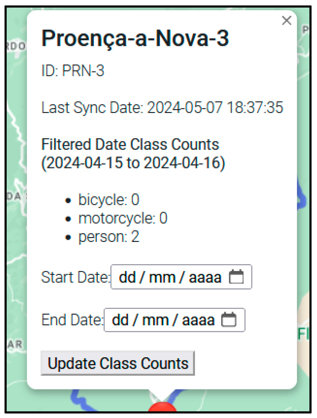
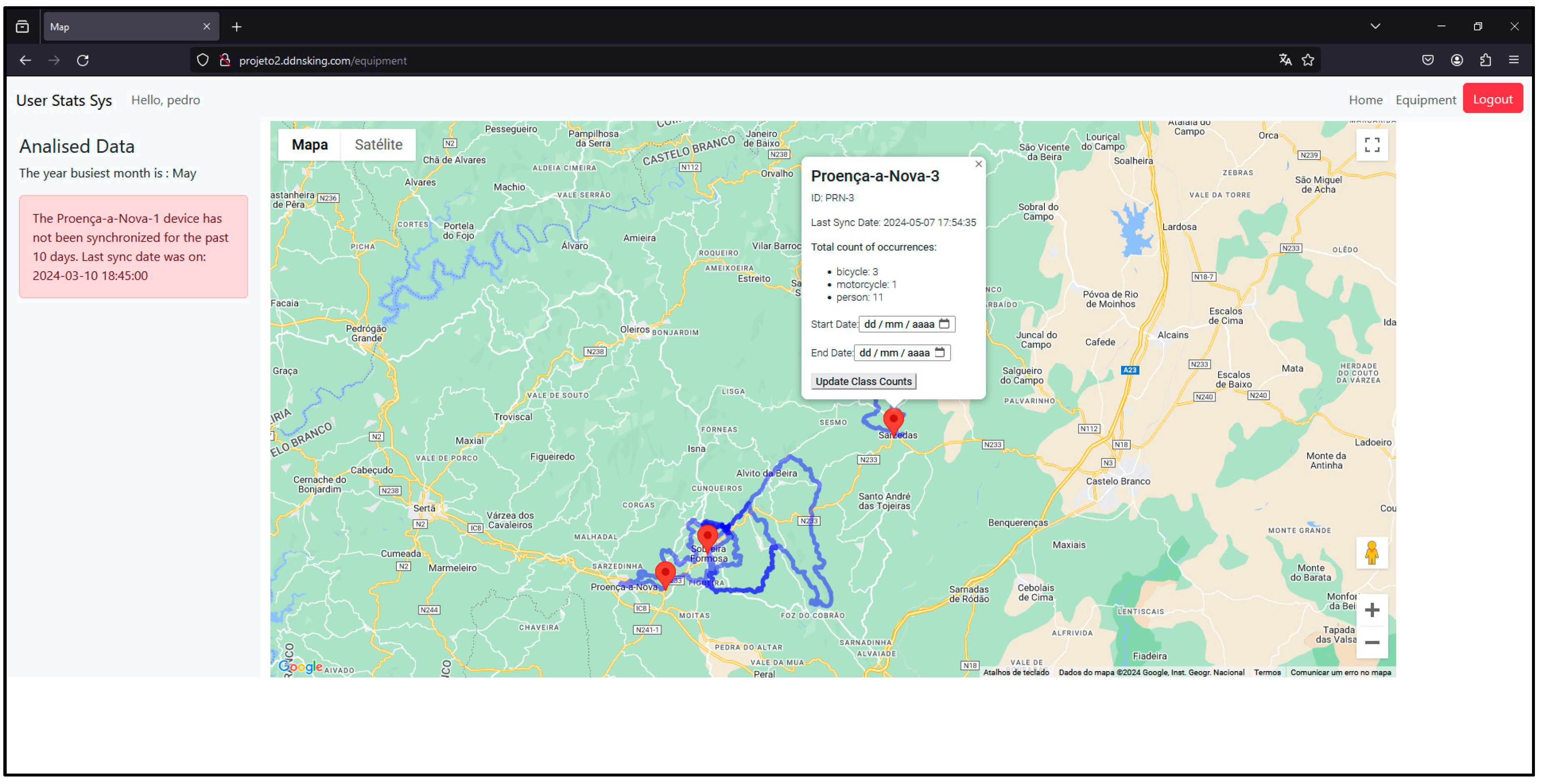
Each marker Information 15 00389 i001 on the map represents a sensor node. If you click on it, an information window will appear showing the name, id and counts of the different types of users it has detected since it has been active (Figure 34).
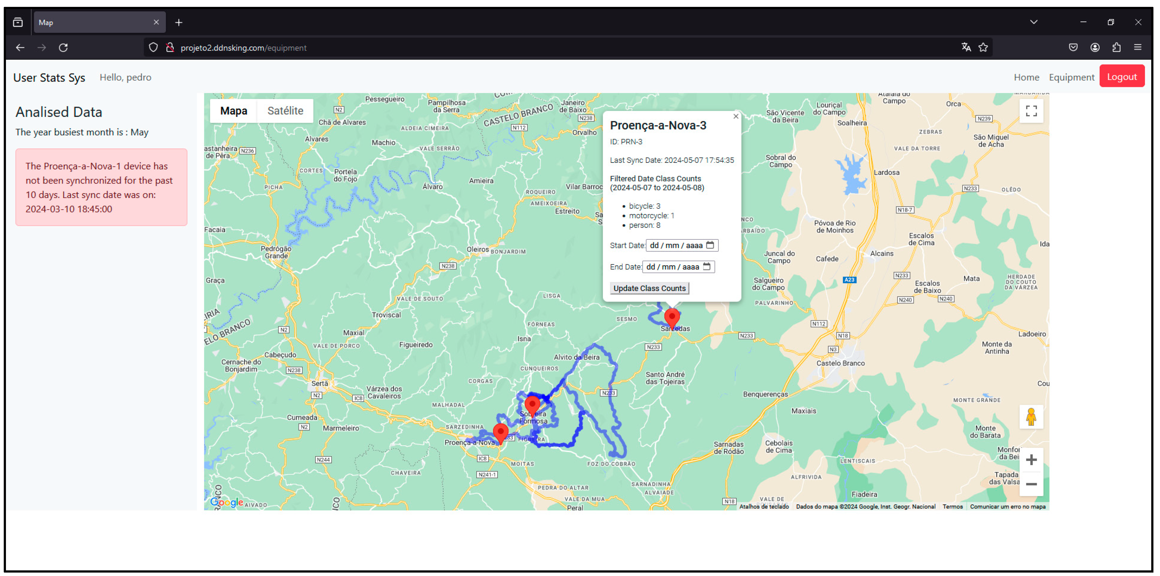
An option is available to filter dates in this window, restricting the time frame. Figure 35 exemplifies this functionality.

3. Testing and Validation

To meet the challenge of detecting and counting different types of users of cycling and hiking trails using computer vision techniques, a dataset was initially created [8]. The performance tests carried out on the YOLOv3-Tiny CNN model applied to that dataset led to the conclusion that it was necessary to increase the number of images identifying the motorcycle and bicycle classes in order to improve YOLOv3-Tiny’s accuracy. The new version of the dataset is available in [77].
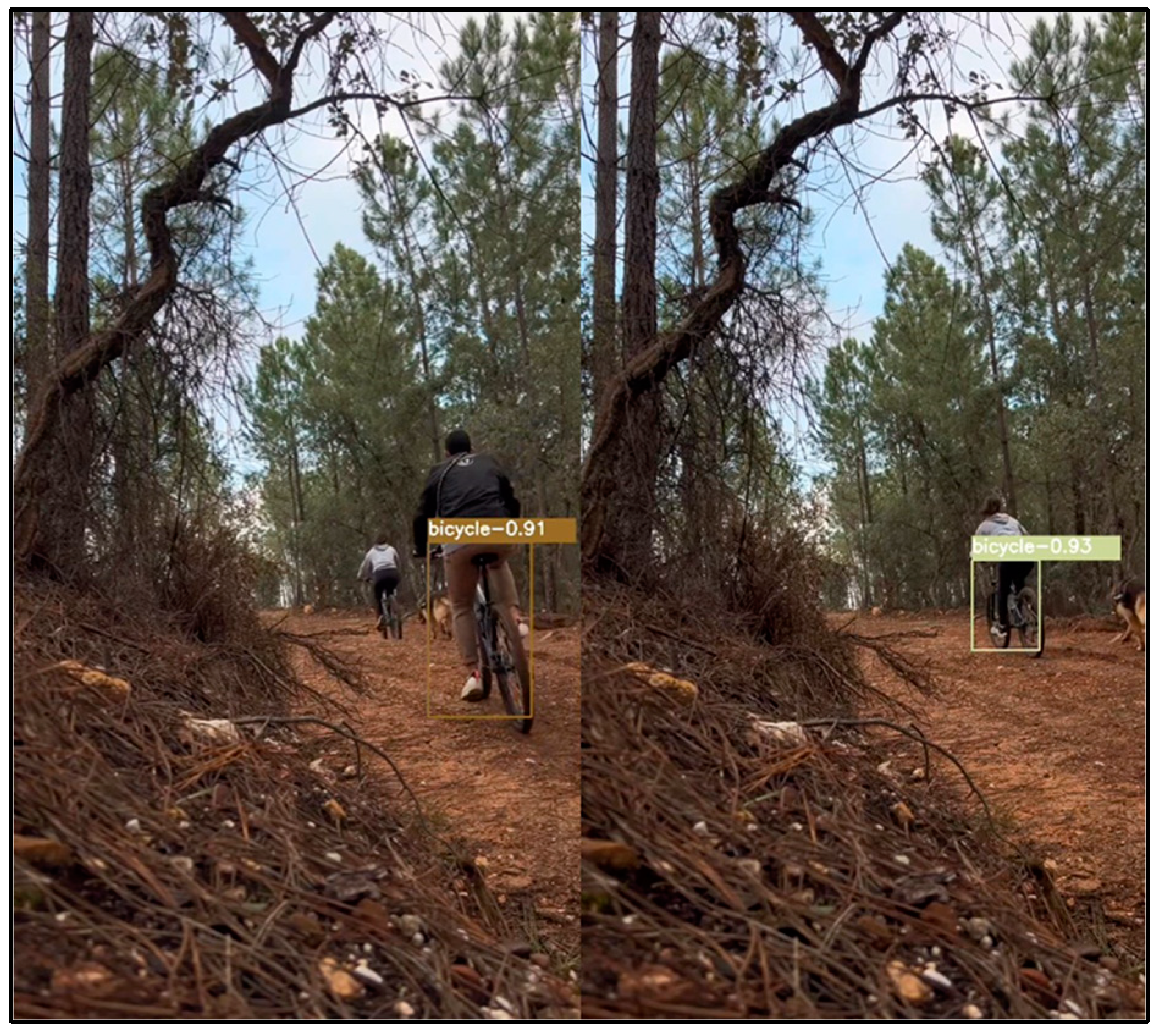
This task, described in the previous section, improved YOLOv3-Tiny’s classification accuracy, as shown in Figure 36. In the previous version of the dataset, these two users, who use a bicycle, were wrongly classified as persons instead of bicycles.
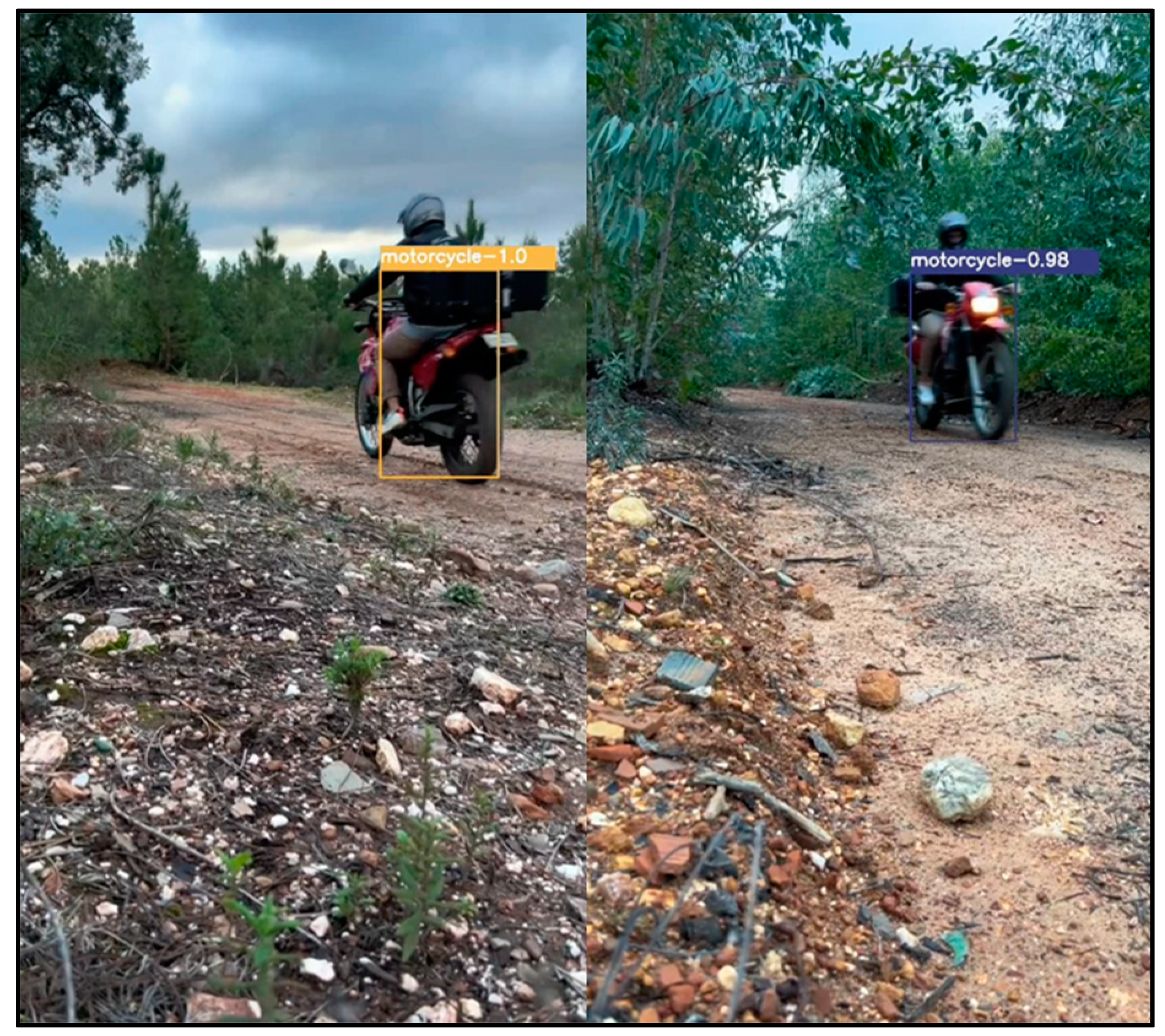
The tests carried out with the previous version of the dataset also revealed some flaws in the classification of the motorcycle class. Some of the detections were sometimes classified as persons. As can be seen in Figure 37, with the new version of the dataset, this type of user is now correctly classified with a very high degree of certainty.
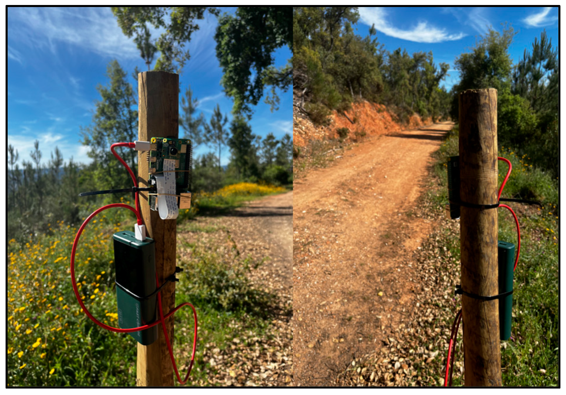
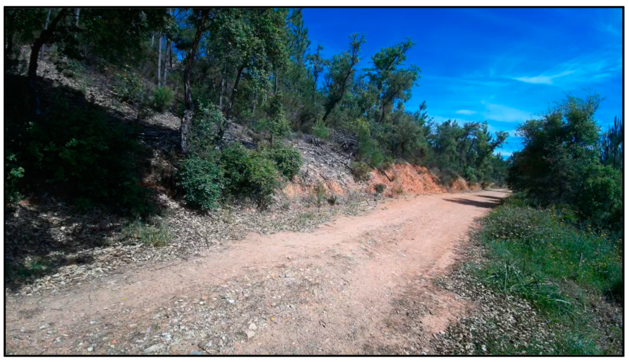
To conduct a set of tests to validate and prove the concept of the proposed prototype described in the previous section, a stake was driven into the ground to simulate the ideal height for positioning the hardware. The sensor node was then attached to the stake with plastic clamps and powered by a portable battery, as can be seen in Figure 38. The sensor node was thus pointed toward the length of the route shown in Figure 39. It is assumed that when the sensor nodes are installed on the trail, their GPS coordinates are recorded in the central database.
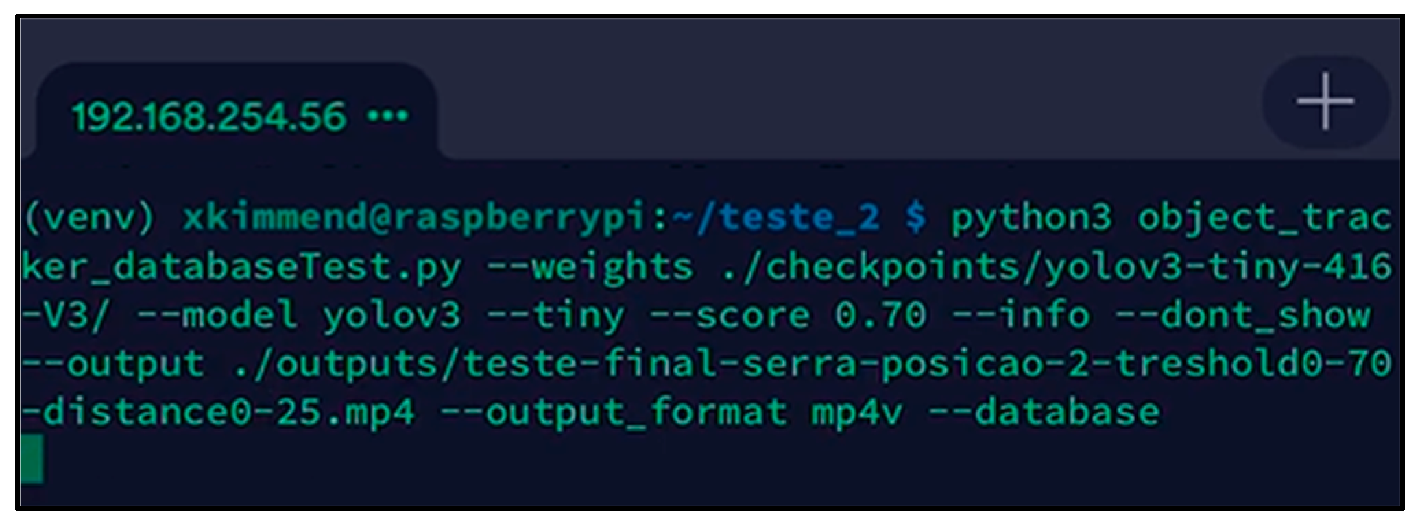
Once the sensor node was attached, the tests began. For demonstration purposes, an access point and an auxiliary smartphone were used to establish a remote connection via SSH with the sensor node. This connection, made using the Terminus application [78], was used to check the results of different types of users’ detection and classification. Figure 40 shows that this auxiliary smartphone is already connected via SSH and ready to run the detection and classification script on the sensor node.
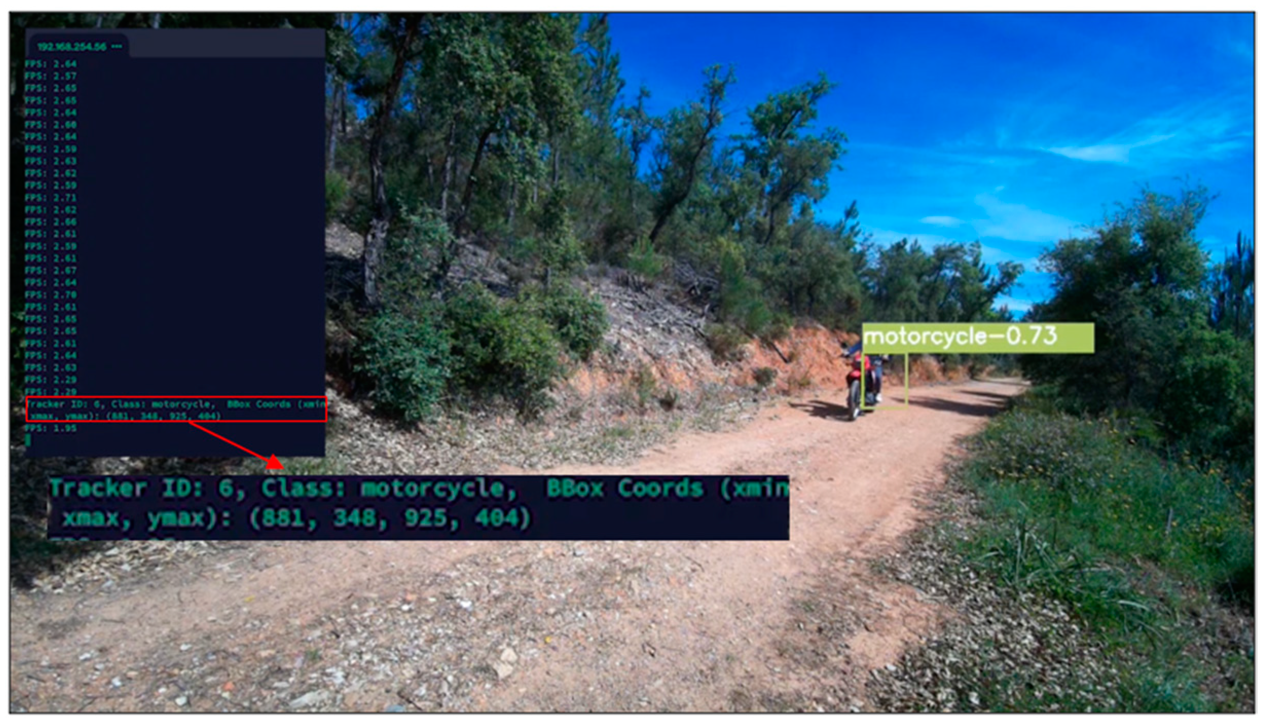
The command shown in Figure 40 executes the script “object_tracker_databaseTest.py”. It uses the YOLOv3-Tiny model for detection, with pre-trained weights located in the “./checkpoints/yolov3-tiny-416-V3” directory. These weights are already adjusted with the new version of the dataset. The “--score 0.70” parameter defines the minimum confidence threshold to consider a detection valid. The “--info” argument activates the display of detailed information on detections and classifications during execution. The “--dont_show” parameter disables the real-time display of detections and ratings. Since the operating system does not have a graphic interface either, this was not possible. The result of the detections and classifications will be saved in a video in MP4 format, whose path and name are specified by “--output ./outputs/test-final-saw-position-2-threshold0-70-distance-0-25.mp4”. This parameter is only used for testing and validating the prototype. In addition, the “--database” parameter relates to the functionality of detections and classifications being recorded in the local database. After running the Python script to start detecting and classifying users, we began by testing the classification of the motorcycle class (Figure 41).
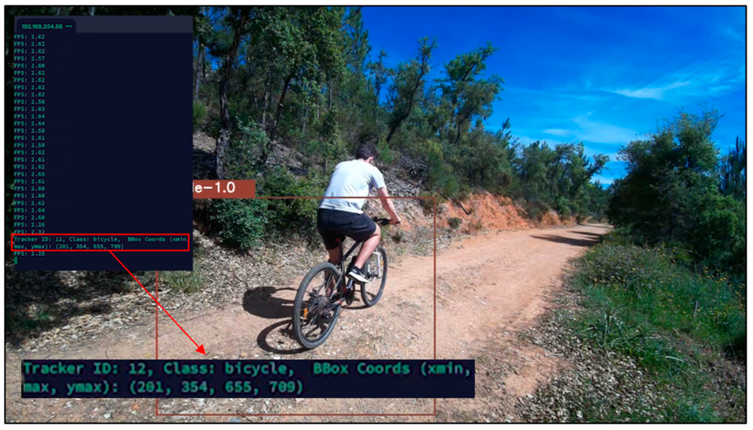
Figure 41 shows that the YOLOv3-Tiny model correctly identifies the motorcycle class, with a certainty of 73%. Tests were then carried out to check the classification accuracy of the bicycle class. Figure 42 shows that the classification is perfect, with 100% certainty that the object belongs to the bicycle class.
The next test evaluated a scenario that was prone to classifying two classes simultaneously, which in this case were the person and bicycle classes. Looking at Figure 43, it can be concluded that the person is correctly classified with 98% certainty, while the user who is using the bicycle is incorrectly classified as a person with 73% certainty. This error is caused by the great distance of this user from the sensor node.
The last test carried out aimed to evaluate the classification of the person class. The test consisted of two users walking side by side. As we can see in Figure 44, the users were correctly classified with certainties of 97% and 99%, even at a considerable distance.
It can be concluded that the results obtained in the different detection and classification tests are satisfactory. It should be explained that the difficulty associated with detecting and classifying the motorcycle class is related to the low computing power of Raspberry (sensor node) and the high speed at which this type of user moves. After this last test, a total of 12 detections were carried out, leaving the sensor node database with the records shown in Figure 45.
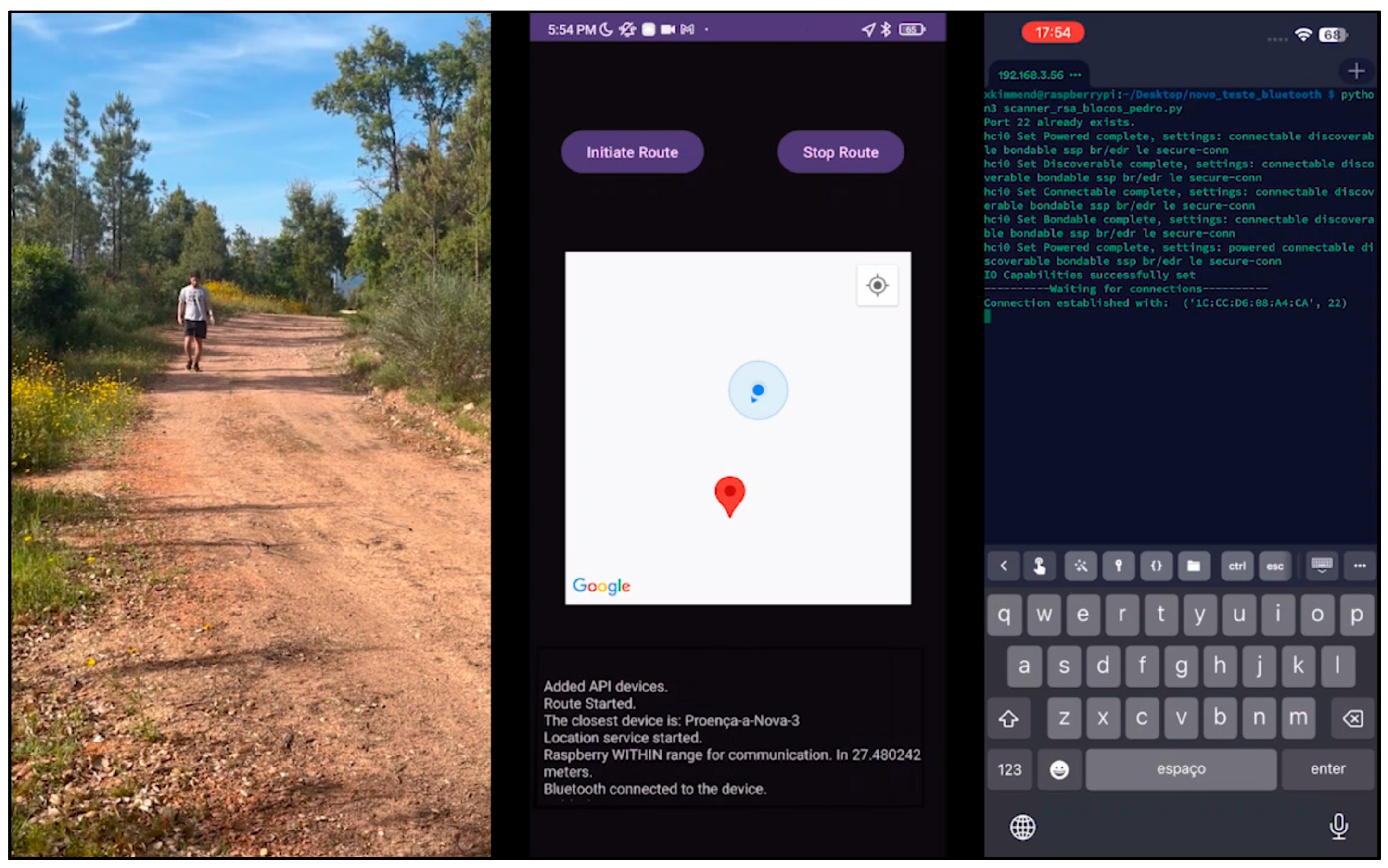
After a few hours, the passage of a new user was simulated, who would play the role of the bridge node. This user, classified as a person, started the trail by selecting the “Initiate Route” option in the mobile application. His route started approximately 27 m from the “PRN-3” sensor node, as shown in Figure 46. As the user moves along the route and enters the Bluetooth range of the sensory node, the nodes negotiate and establish a connection (Figure 46).
The sensor node then sends its records to the bridge node. The service used to synchronize the data from the bridge node to the central database, which is hosted on a server on the Internet, is initialized and remains in the background, waiting for an Internet connection, as shown in Figure 47.
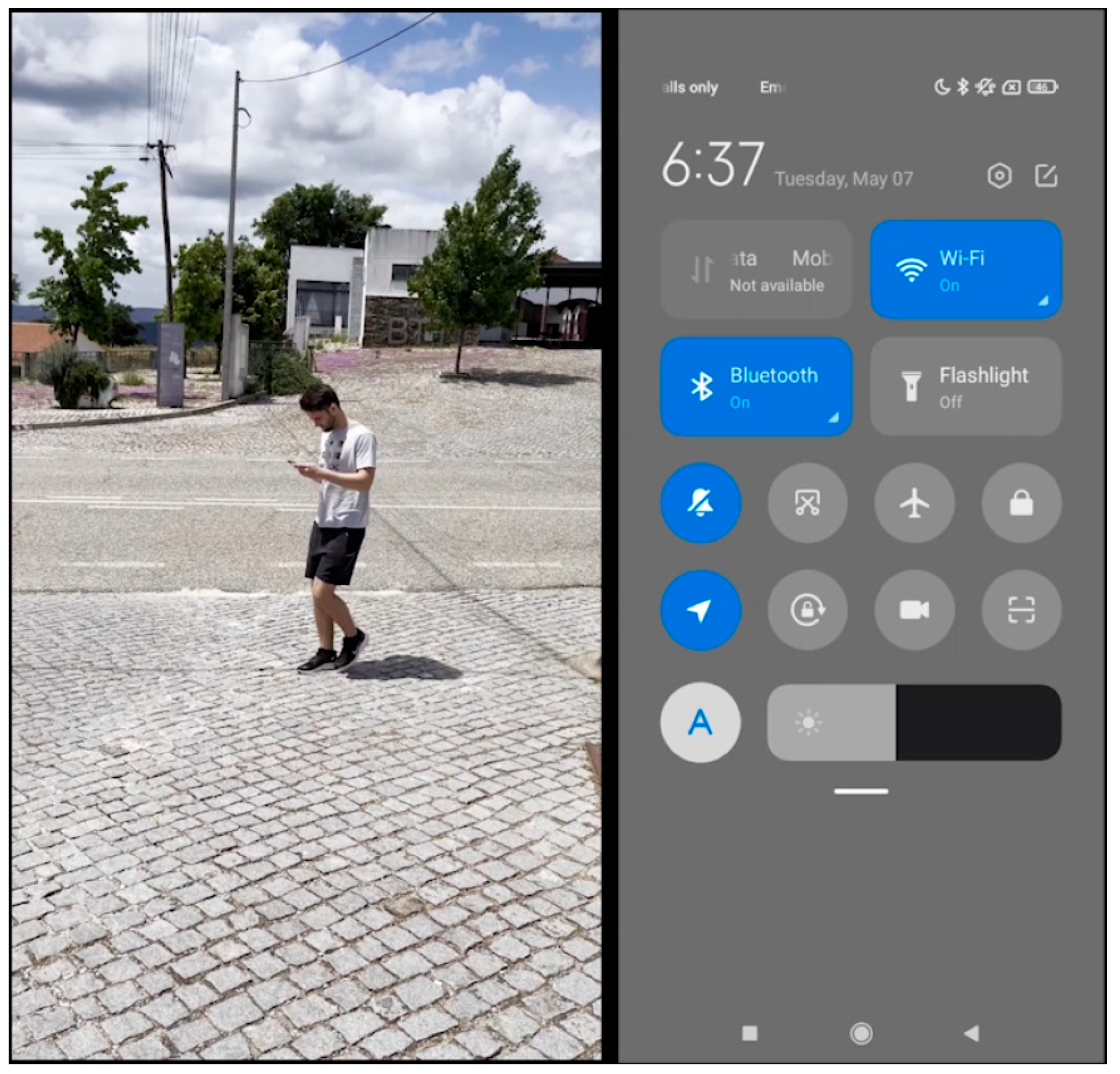
As illustrated in Figure 48, later in the day, the user went to a location that has access to a Wi-Fi network but could also use a 3G/4G/5G connection. In this case, the Android device’s Wi-Fi is activated and it connects to the Internet.
Once this connection has been established, the service successfully synchronizes the data with the central database, as seen in Figure 49.
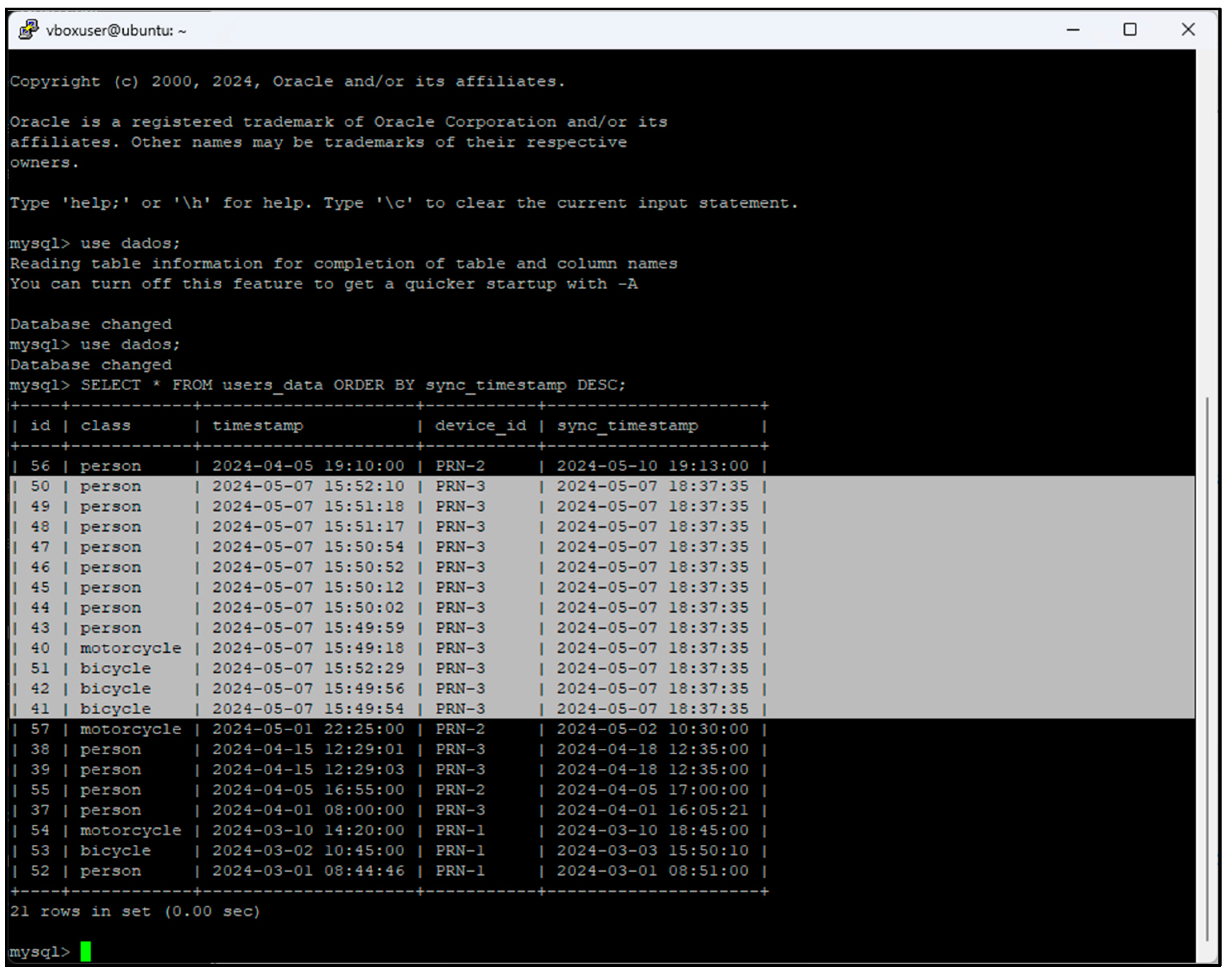
After this iteration, the records with the detections and classifications of the different types of users are already in the central database hosted on a server on the Internet. Figure 50 shows these new 12 detected records.
The information collected by the sensor and bridge nodes, now stored in the central database, can now be viewed in the web application. After logging in and accessing the main page, it is possible to apply filters to the information. The device responsible for these detections and classifications is the “Proença-a-Nova-3” sensor node, with the ID “PRN-3”, which is why it was selected. It is possible to see the counts of the three classes since this sensor node has been in operation. If filtering is applied with a start and end date, the counts of each class are displayed individually, totaling 12 records, as seen in Figure 51.
In Figure 52, it is possible to see the same counts by class in “PRN-3” but now on the page showing the map and the sensor nodes distributed on the ground. By filtering the start and end dates for the day on which the detections were made, it can be seen that there are 12 records again, separated by their classes, as shown in Figure 53.

4. Conclusions and Future Work

In Portugal, the number of approved cycling and hiking trails has been growing over the years, helping to add value to areas by attracting a growing number of domestic and foreign tourists to practice nature sports. However, since these are open-access spaces, there is usually no reliable data on the rate of use. Knowing the number of visitors and identifying the different types of users as well as the peak periods are examples of valuable information for those who have to manage and promote these resources, and also demonstrate their strategic importance in terms of tourism development, especially in low-density territories.
The main aim of this study was to propose and evaluate a solution that makes it possible to identify and count different types of users of cycling and hiking trails. This study has sought, based on the study of the state of the art and the initial performance evaluation conducted by the same authors in [8], to present a proposal, implementation, testing and validation of a prototype with a “proof-of-concept”.
The main contributions of this study are as follows: the expansion of the dataset [8] with a new version now available in [77] and the additional tests carried out on the YOLOV3-Tiny model; the definition of an architecture, as well as the hardware and software components of a low-cost prototype, based on the Internet of Things, computer vision (CNNs) and the concept of opportunistic networks; the description of its implementation and configuration process; and finally, the validation and proof-of-concept tests carried out on the prototype.
The prototype proved to be effective as it achieved the objectives proposed in its design. It is considered an economically viable and functional option.
In future work, it is essential to highlight the importance of security in communication between the system’s nodes, especially in the context of data transmission via Bluetooth technology. Given the constant evolution of the technological world, it is important to keep up with this progress and strengthen security measures to prevent potential attacks on the system. A comprehensive review of communication security will therefore be necessary, implementing more advanced encryption protocols to protect the data transmitted.
Should the product be marketed, it will be important for it to have an operating system prepared to be used in a “plug and play” (PnP) manner, making it easy for infrastructure managers to implement and adopt it, without the need for complex configurations or extensive customizations.
It will also be necessary to develop a computer numerical control (CNC) enclosure/box to accommodate the prototype’s electronic components, allowing it to be tested in real conditions, subject to adverse weather conditions.
To improve the accuracy and robustness of the system in different environmental conditions and situations of use, it is essential to explore more advanced artificial intelligence and learning techniques to significantly improve the system’s ability to detect and classify different types of users.
Power consumption and energy efficiency are crucial issues because the presented IoT solution will be battery-operated and thus energy-constrained. Thus, work remains to be done in terms of analyzing battery lifetime and power consumption, as well as optimizing battery lifetime. A solar panel may be added. The importance of a presence detector (e.g., motion detector or infrared) to trigger inference and data exchange will also need to be assessed.
Finally, it is necessary to improve the interface and functionalities of the mobile application and online platform. This will involve not only esthetic improvements, but also the application of usability and user experience concepts, making them more intuitive and easier to use.

Author Contributions

Conceptualization, J.M., P.M. and A.Q.; methodology, J.M. and P.M.; validation, J.M.L.P.C. and V.N.G.J.S.; formal analysis, J.M.L.P.C. and V.N.G.J.S.; investigation, J.M. and P.M.; writing—original draft preparation, J.M. and P.M.; writing—review and editing, A.Q., J.M.L.P.C. and V.N.G.J.S.; supervision, J.M.L.P.C. and V.N.G.J.S.; funding acquisition, J.M.L.P.C. and V.N.G.J.S. All authors have read and agreed to the published version of the manuscript.

Funding

J.M.L.P.C. and V.N.G.J.S. acknowledge that this study is funded by FCT/MCTES through national funds and, where applicable, co-funded by EU funds under the project UIDB/50008/2020.

Institutional Review Board Statement

Not applicable.

Informed Consent Statement

Not applicable.

Data Availability Statement

The original contributions presented in the study are included in the article.

Conflicts of Interest

The authors declare no conflicts of interest.

References

  1. Federação de Campismo e Montanhismo de Portugal. Regulamento de Homologação De Percursos; Federação de Campismo e Montanhismo de Portugal: Lisboa, Portugal, 2006. [Google Scholar]
  2. Saos Sinalização. Available online: http://www.solasrotas.org/2008/09/sinalizao.html (accessed on 9 December 2023).
  3. Carvalho, P. Pedestrianismo e Percursos Pedestres. Cad. De Geogr. 2009, 28/29, 193–204. [Google Scholar]
  4. Federação de Campismo e Montanhismo de Portugal Site Oficial Da FCMP. Available online: https://www.fcmportugal.com/ (accessed on 16 January 2024).
  5. Federação de Campismo e Montanhismo de Portugal Site Oficial Da FCMP-Percursos Pedestres. Available online: https://www.fcmportugal.com/percursos-pedestres/ (accessed on 9 December 2023).
  6. Rails to Trails Conservancy Trail User Surveys and Counting. Available online: https://www.railstotrails.org/trail-building-toolbox/trail-user-surveys-and-counting/ (accessed on 18 May 2024).
  7. Lawson, M. Innovative New Ways to Count Outdoor Recreation: Using Data from Cell Phones, Fitness Trackers, Social Media, and Other Novel Data Sources; Headwaters Econ: Bozeman, MT, USA, 2021. [Google Scholar]
  8. Miguel, J.; Mendonça, P.; Quelhas, A.; Caldeira, J.M.L.P.; Soares, V.N.G.J. Using Computer Vision to Collect Information on Cycling and Hiking Trails Users. Future Internet 2024, 16, 104. [Google Scholar] [CrossRef]
  9. Adarsh, P.; Rathi, P.; Kumar, M. YOLO V3-Tiny: Object Detection and Recognition Using Stage Improved Model. In Proceedings of the 2020 6th International Conference on Advanced Computing & Communication Systems (ICACCS), Coimbatore, India, 6 March 2020; pp. 687–694. [Google Scholar]
  10. Sandler, M.; Howard, A.; Zhu, M.; Zhmoginov, A.; Chen, L.-C. MobileNetV2: Inverted Residuals and Linear Bottlenecks. In Proceedings of the IEEE Conference on Computer Vision and Pattern Recognition (CVPR), Salt Lake City, UT, USA, 18–23 June 2018; pp. 4510–4520. [Google Scholar]
  11. Wu, H.; Xin, M.; Fang, W.; Hu, H.M.; Hu, Z. Multi-Level Feature Network with Multi-Loss for Person Re-Identification. IEEE Access 2019, 7, 91052–91062. [Google Scholar] [CrossRef]
  12. Rodrigues, J.J.P.C.; Soares, V.N.G.J. Cooperation in DTN-Based Network Architectures. In Cooperative Networking; John Wiley & Sons, Ltd.: Hoboken, NJ, USA, 2011; pp. 101–115. [Google Scholar]
  13. Rodrigues, J.J.P.C.; Soares, V.N.G.J. An Introduction to Delay and Disruption-Tolerant Networks (DTNs). In Advances in Delay-Tolerant Networks (DTNs): Architecture and Enhanced Performance; Woodhead Publishing: Thorston, UK, 2014; pp. 1–21. [Google Scholar]
  14. Cerf, V.; Burleigh, S.; Hooke, A.; Torgerson, L.; Durst, R.; Scott, K.; Fall, K.; Weiss, H. Delay-Tolerant Networking Architecture. 2007. Available online: https://www.rfc-editor.org/info/rfc4838 (accessed on 30 April 2024).
  15. Videira, J.; Gaspar, P.D.; Soares, V.N.G.J.; Caldeira, J.M.L.P. A Mobile Application for Detecting and Monitoring the Development Stages of Wild Flowers and Plants. Informatica 2024, 48, 5645. [Google Scholar] [CrossRef]
  16. Videira, J.; Gaspar, P.D.; de Jesus Soares, V.N.d.G.; Caldeira, J.M.L.P. Detecting and Monitoring the Development Stages of Wild Flowers and Plants Using Computer Vision: Approaches, Challenges and Opportunities. Int. J. Adv. Intell. Inform. 2023, 9, 347–362. [Google Scholar] [CrossRef]
  17. Rodrigues, J.J.P.C.; Soares, V.N.G.J.; Farahmand, F. Stationary Relay Nodes Deployment on Vehicular Opportunistic Networks; Denko, M.K., Ed.; Auerbach Publications: Boca Raton, FL, USA, 2016; ISBN 97814-20088137. [Google Scholar]
  18. Soares, V.N.G.J.; Rodrigues, J.J.P.C.; Farahmand, F.; Denko, M. Exploiting Node Localization for Performance Improvement of Vehicular Delay-Tolerant Networks. In Proceedings of the IEEE International Conference on Communications, Cape Town, South Africa, 23 May 2010; pp. 1–5. [Google Scholar]
  19. Verma, M.; Singh, S.; Kaur, B. An Overview of Bluetooth Technology and Its Communication Applications. Int. J. Curr. Eng. Technol. 2015, 5, 1588–1592. [Google Scholar]
  20. Alecrim, E. Bluetooth: O Que é, Como Funciona e Versões. Available online: https://www.infowester.com/bluetooth.php (accessed on 30 April 2024).
  21. Collotta, M.; Pau, G.; Talty, T.; Tonguz, O.K. Bluetooth 5: A Concrete Step Forward toward the IoT. IEEE Commun. Mag. 2018, 56, 125–131. [Google Scholar] [CrossRef]
  22. He, N. Bluetooth VS WiFi VS Zigbee: Which Wireless Technology Is Better. Available online: https://www.mokosmart.com/bluetooth-vs-wifi-vs-zigbee-which-is-better/ (accessed on 13 May 2024).
  23. Putra, G.D.; Pratama, A.R.; Lazovik, A.; Aiello, M. Comparison of Energy Consumption in Wi-Fi and Bluetooth Communication in a Smart Building. In Proceedings of the 2017 IEEE 7th Annual Computing and Communication Workshop and Conference, CCWC 2017, Las Vegas, NV, USA, 9–11 January 2017. [Google Scholar]
  24. Spyropoulos, T.; Psounis, K.; Raghavendra, C.S. Spray and Wait: An Efficient Routing Scheme for Intermittently Connected Mobile Networks. In WDTN ’05: Proceedings of the ACM SIGCOMM Workshop on Delay-Tolerant Networking, Philadelphia, PA, USA, 22 August 2005; Association for Computing Machinery: New York, NY, USA; pp. 252–259.
  25. Soares, V.N.G.J.; Rodrigues, J.J.P.C.; Dias, J.A.; Isento, J.N. Performance Analysis of Routing Protocols for Vehicular Delay-Tolerant Networks. In Proceedings of the SoftCOM, 20th International Conference on Software, Telecommunications and Computer Networks, Split, Croatia, 11–13 September 2012. [Google Scholar]
  26. Raspberry Pi Raspberry Pi 4 Model B. Available online: https://www.raspberrypi.com/products/raspberry-pi-4-model-b/ (accessed on 29 April 2024).
  27. Raspberry Pi Raspberry Pi Camera Module 3. Available online: https://www.raspberrypi.com/products/camera-module-3/ (accessed on 29 April 2024).
  28. Shehab, M.A.; Al-Gizi, A.; Swadi, S.M. Efficient Real-Time Object Detection Based on Convolutional Neural Network. In Proceedings of the 2021 International Conference on Applied and Theoretical Electricity, ICATE 2021-Proceedings, Craiova, Romania, 27–29 May 2021. [Google Scholar]
  29. Xu, W.; Li, W.; Wang, L. Research on Image Recognition Methods Based on Deep Learning. Appl. Math. Nonlinear Sci. 2024, 9, 1–14. [Google Scholar] [CrossRef]
  30. Bhatt, D.; Patel, C.; Talsania, H.; Patel, J.; Vaghela, R.; Pandya, S.; Modi, K.; Ghayvat, H. CNN Variants for Computer Vision: History, Architecture, Application, Challenges and Future Scope. Electronics 2021, 10, 2470. [Google Scholar] [CrossRef]
  31. Barbosa, G.; Bezerra, G.M.; de Medeiros, D.S.; Andreoni Lopez, M.; Mattos, D. Segurança Em Redes 5G: Oportunidades e Desafios Em Detecção de Anomalias e Predição de Tráfego Baseadas Em Aprendizado de Máquina. In Proceedings of the XXI Simpósio Brasileiro em Segurança da Informação e de Sistemas Computacionais (SBSeg 2021), Belém, Brazil, 4–7 October 2021; pp. 164–165. [Google Scholar] [CrossRef]
  32. Poloni, K. Redes Neurais Convolucionais. Available online: https://medium.com/itau-data/redes-neurais-convolucionais-2206a089c715 (accessed on 1 November 2023).
  33. Archana, V.; Kalaiselvi, S.; Thamaraiselvi, D.; Gomathi, V.; Sowmiya, R. A Novel Object Detection Framework Using Convolutional Neural Networks (CNN) and RetinaNet. In Proceedings of the International Conference on Automation, Computing and Renewable Systems, ICACRS 2022-Proceedings, Pudukkottai, India, 13–15 December 2022; pp. 1070–1074. [Google Scholar]
  34. Carranza-García, M.; Torres-Mateo, J.; Lara-Benítez, P.; García-Gutiérrez, J. On the Performance of One-Stage and Two-Stage Object Detectors in Autonomous Vehicles Using Camera Data. Remote Sens. 2020, 13, 89. [Google Scholar] [CrossRef]
  35. Zhou, L.; Lin, T.; Knoll, A. Fast and Accurate Object Detection on Asymmetrical Receptive Field. arXiv 2023, arXiv:2303.08995. [Google Scholar]
  36. Thakur, N. A Detailed Introduction to Two Stage Object Detectors. Available online: https://namrata-thakur893.medium.com/a-detailed-introduction-to-two-stage-object-detectors-d4ba0c06b14e (accessed on 23 December 2023).
  37. Redmon, J.; Farhadi, A. YOLOv3: An Incremental Improvement. arXiv 2018, arXiv:1804.02767. [Google Scholar]
  38. Koteswararao, M.; Karthikeyan, P.R. Comparative Analysis of YOLOv3-320 and YOLOv3-Tiny for the Optimised Real-Time Object Detection System. In Proceedings of the 3rd International Conference on Intelligent Engineering and Management, ICIEM 2022, London, UK, 27–29 April 2022; pp. 495–500. [Google Scholar]
  39. Khokhlov, I.; Davydenko, E.; Osokin, I.; Ryakin, I.; Babaev, A.; Litvinenko, V.; Gorbachev, R. Tiny-YOLO Object Detection Supplemented with Geometrical Data. In Proceedings of the IEEE Vehicular Technology Conference, Antwerp, Belgium, 1 May 2020. [Google Scholar]
  40. Chen, S.; Lin, W. Embedded System Real-Time Vehicle Detection Based on Improved YOLO Network. In Proceedings of the 2019 IEEE 3rd Advanced Information Management, Communicates, Electronic and Automation Control Conference, IMCEC 2019, Chongqing, China, 1 October 2019; pp. 1400–1403. [Google Scholar]
  41. Miguel, J.; Mendonça, P. Person, Bicycle and Motorcyle Dataset. Available online: https://universe.roboflow.com/projeto-gfvuy/person-bicycle-motorcyle/model/7 (accessed on 26 January 2024).
  42. Google Colab. Available online: https://colab.google/ (accessed on 22 December 2023).
  43. Roboflow, Inc. Roboflow Website. Available online: https://roboflow.com/ (accessed on 22 November 2023).
  44. Roboflow Notebook-Train Yolov4 Tiny Object Detection On Custom Data. Available online: https://github.com/roboflow/notebooks/blob/main/notebooks/train-yolov4-tiny-object-detection-on-custom-data.ipynb (accessed on 23 December 2023).
  45. NVIDIA NVIDIA CUDA Compiler Driver. Available online: https://docs.nvidia.com/cuda/cuda-compiler-driver-nvcc/index.html (accessed on 23 December 2023).
  46. Darknet Darknet: Open Source Neural Networks in C. Available online: https://pjreddie.com/darknet/ (accessed on 23 December 2023).
  47. Charette, S. Programming Comments-Darknet FAQ. Available online: https://www.ccoderun.ca/programming/darknet_faq/ (accessed on 28 January 2024).
  48. Lakera Average Precision. Available online: https://www.lakera.ai/ml-glossary/average-precision (accessed on 17 January 2024).
  49. btd Performance Insights: Train Loss vs. Test Loss in Machine Learning Models|Medium. Available online: https://baotramduong.medium.com/machine-learning-train-loss-vs-test-loss-735ccd713291 (accessed on 14 May 2024).
  50. Raspberry Raspberry Pi OS (Legacy) Lite. Available online: https://downloads.raspberrypi.com/raspios_oldstable_lite_arm64/images/raspios_oldstable_lite_arm64-2024-03-12/2024-03-12-raspios-bullseye-arm64-lite.img.xz (accessed on 9 May 2024).
  51. MariaDB Foundation MariaDB DBMS. Available online: https://mariadb.org/ (accessed on 12 June 2024).
  52. Certificadora, V. Criptografia Simétrica e Assimétrica: Qual é a Diferença Entre Elas? Available online: https://blog.validcertificadora.com.br/criptografia-simetrica-e-assimetrica-qual-e-diferenca-entre-elas/ (accessed on 1 May 2024).
  53. Milanov, E. The RSA Algorithm; RSA laboratories: Burlington, MA, USA, 2009. [Google Scholar]
  54. Evans, D.L.; Brown, K.H. Advanced Encryption Standard (AES); National Institute of Standards and Technology: Gaithersburg, MD, USA, 2001. [Google Scholar]
  55. Filatov, I. Hybrid Encryption in Python. Available online: https://medium.com/@igorfilatov/hybrid-encryption-in-python-3e408c73970c (accessed on 1 May 2024).
  56. Bluetooth® Technology RFCOMM. Available online: https://www.bluetooth.com/specifications/specs/rfcomm-1-1/ (accessed on 4 May 2024).
  57. Android Developers BluetoothDevice. Available online: https://developer.android.com/reference/android/bluetooth/BluetoothDevice (accessed on 4 May 2024).
  58. MDN BluetoothUUID. Available online: https://developer.mozilla.org/en-US/docs/Web/API/BluetoothUUID (accessed on 1 May 2024).
  59. W3schools What Is JSON. Available online: https://www.w3schools.com/whatis/whatis_json.asp (accessed on 1 May 2024).
  60. Oracle Corporation Dev.Java: The Destination for Java Developers. Available online: https://dev.java/ (accessed on 30 April 2024).
  61. Google Download Android Studio & App Tools-Android Developers. Available online: https://developer.android.com/studio (accessed on 30 April 2024).
  62. Google Service|Android Developers. Available online: https://developer.android.com/reference/android/app/Service (accessed on 30 April 2024).
  63. Google Activity|Android Developers. Available online: https://developer.android.com/reference/android/app/Activity (accessed on 30 April 2024).
  64. Google Markers|Android Developers. Available online: https://developers.google.com/maps/documentation/android-sdk/marker#maps_android_markers_add_a_marker-java (accessed on 30 April 2024).
  65. Google Salvar Dados Usando o SQLite|Android Developers. Available online: https://developer.android.com/training/data-storage/sqlite?hl=pt-br (accessed on 9 May 2024).
  66. Oracle MySQL. Available online: https://www.mysql.com/ (accessed on 9 May 2024).
  67. Ubuntu 20.04.6 LTS (Focal Fossa). Available online: https://releases.ubuntu.com/20.04.6/?_ga=2.149898549.2084151835.1707729318-1126754318.1683186906 (accessed on 9 May 2024).
  68. Google KML Documentation Introduction|Keyhole Markup Language|Google for Developers. Available online: https://developers.google.com/kml/documentation (accessed on 2 May 2024).
  69. Google Keyhole Markup Language|Google for Developers. Available online: https://developers.google.com/kml (accessed on 2 May 2024).
  70. dassouki Gis-Loading a Local.Kml File Using Google Maps?-Stack Overflow. Available online: https://stackoverflow.com/questions/3514785/loading-a-local-kml-file-using-google-maps (accessed on 2 May 2024).
  71. ScaisEdge Google Maps-Unable to Access KML File for KML Layer|Stackoverflow. Available online: https://stackoverflow.com/questions/35851509/google-maps-unable-to-access-kml-file-for-kml-layer (accessed on 16 May 2024).
  72. nrabinowitz Google Maps API and KML File LocalHost Development Options|Stackoverflow. Available online: https://stackoverflow.com/questions/6092110/google-maps-api-and-kml-file-localhost-development-options (accessed on 16 May 2024).
  73. Burke, K.; Conroy, K.; Horn, R.; Stratton, F.; Binet, G. Flask-RESTful—Flask-RESTful 0.3.10 Documentation. Available online: https://flask-restful.readthedocs.io/en/latest/ (accessed on 4 May 2024).
  74. Le Wagon O Que é Padrão MVC? Entenda Arquitetura de Softwares! Available online: https://blog.lewagon.com/pt-br/skills/o-que-e-padrao-mvc/ (accessed on 2 May 2024).
  75. Pallets Projects Flask. Available online: https://flask.palletsprojects.com/en/3.0.x/ (accessed on 2 May 2024).
  76. Google. Google for Developers-API Maps JavaScript. Available online: https://developers.google.com/maps/documentation/javascript/overview?hl=pt-br (accessed on 2 May 2024).
  77. Miguel, J.; Mendonça, P. Person,Bicycle,Motorcyle Dataset > Overview. Available online: https://app.roboflow.com/projeto-gfvuy/person-bicycle-motorcyle/overview (accessed on 24 May 2024).
  78. Termius Termius-SSH Platform for Mobile and Desktop. Available online: https://termius.com/ (accessed on 9 May 2024).
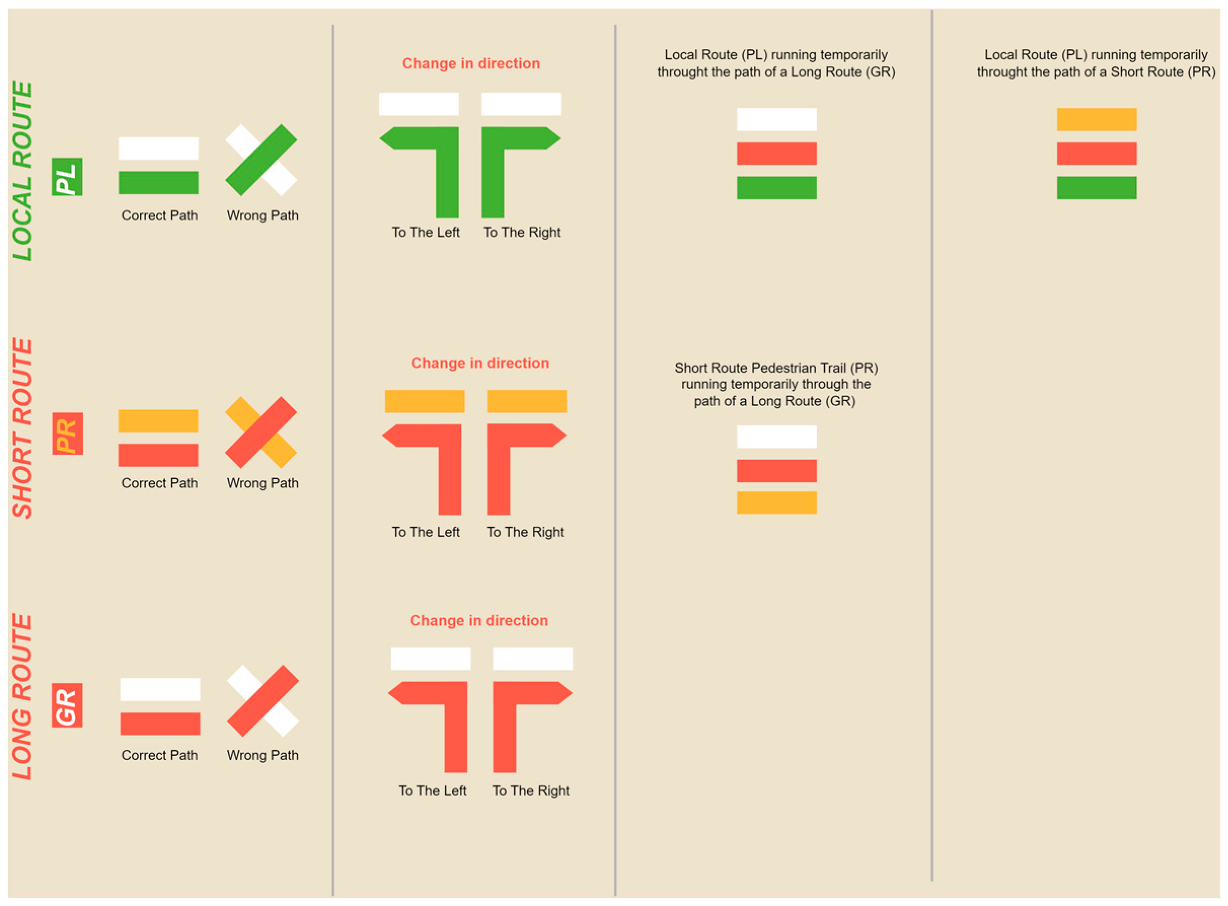
Figure 1. The signage utilized along the trails.
Information 15 00389 g001
Figure 2. Examples of marked places.
Information 15 00389 g002
Figure 3. An illustration of the scenario.
Information 15 00389 g003
Figure 4. Prototype architecture.
Information 15 00389 g004
Figure 5. The IoT device from the prototype’s sensor node.
Information 15 00389 g005
Figure 6. Convolutional neural network structure.
Information 15 00389 g006
Figure 7. Classification of one-stage detection and two-stage detection model types in object detection.
Information 15 00389 g007
Figure 8. One-stage detection model architecture.
Information 15 00389 g008
Figure 9. Two-stage detection model architecture.
Information 15 00389 g009
Figure 10. 3 × 3 grid division.
Information 15 00389 g010
Figure 11. Architecture of YOLOv3-Tiny model.
Information 15 00389 g011
Figure 12. Representation of bounding boxes for each class.
Information 15 00389 g012
Figure 13. (a) Training loss and mAP of first training using YOLOv3-Tiny. (b) Training loss and mAP of new training using YOLOv3-Tiny.
Information 15 00389 g013
Figure 14. A flowchart of the detection and classification algorithm.
Information 15 00389 g014
Figure 15. Sensor node local database.
Information 15 00389 g015
Figure 16. Hybrid cryptosystem.
Information 15 00389 g016
Figure 17. Connection to Bluetooth service and exchange of RSA public keys.
Information 15 00389 g017
Figure 18. Process of preparing to transmit data.
Information 15 00389 g018
Figure 19. An illustration of a scenario in which a user using a bicycle passes within range of the Bluetooth signal from the sensor node.
Information 15 00389 g019
Figure 20. Example of block of 10 records in JSON.
Information 15 00389 g020
Figure 21. Communication between nodes when transmitting data.
Information 15 00389 g021
Figure 22. Mobile application screen.
Information 15 00389 g022
Figure 23. The output on the mobile application with information on the route started and the location of the nodes.
Information 15 00389 g023
Figure 24. Output of data exchange between nodes.
Information 15 00389 g024
Figure 25. Bridge node local database.
Information 15 00389 g025
Figure 26. Output from synchronization service.
Information 15 00389 g026
Figure 27. A flowchart describing how the bridge node application works.
Information 15 00389 g027
Figure 28. Central database.
Information 15 00389 g028
Figure 29. GET method for obtaining information from sensor nodes.
Information 15 00389 g029
Figure 30. POST method for sending and creating records.
Information 15 00389 g030
Figure 31. Login page of web application.
Information 15 00389 g031
Figure 32. Main page of web application.
Information 15 00389 g032
Figure 33. A web application page with a view of the trails and sensor nodes.
Information 15 00389 g033
Figure 34. A web application page with information on the sensor node selected by the user.
Information 15 00389 g034
Figure 35. Filtering by time period in a sensor node.
Information 15 00389 g035
Figure 36. Example of detection with YOLOv3-Tiny model trained with improved dataset.
Information 15 00389 g036
Figure 37. Second example of detection with YOLOv3-Tiny model trained with improved dataset.
Information 15 00389 g037
Figure 38. Positioning the sensor node on the ground.
Information 15 00389 g038
Figure 39. Part of the trail captured by the sensor node.
Information 15 00389 g039
Figure 40. SSH connection to the sensor node via the Terminus application.
Information 15 00389 g040
Figure 41. Classification and detection of motorcycle class.
Information 15 00389 g041
Figure 42. Classification and detection of bicycle class.
Information 15 00389 g042
Figure 43. Simultaneous identification of person and bicycle classes.
Information 15 00389 g043
Figure 44. Simultaneous identification of person class.
Information 15 00389 g044
Figure 45. The records in the sensor node database.
Information 15 00389 g045
Figure 46. Starting the trail and connection establishment.
Information 15 00389 g046
Figure 47. Data exchange between nodes and initialization of synchronization service.
Information 15 00389 g047
Figure 48. Activating Wi-Fi on the Android device.
Information 15 00389 g048
Figure 49. Data synchronized with central database.
Information 15 00389 g049
Figure 50. Records in central database.
Information 15 00389 g050
Figure 51. Class counts in PRN-3, filtered by detection dates.
Information 15 00389 g051
Figure 52. The class counts in PRN-3 on the page showing the map and the sensor nodes distributed on the ground.
Information 15 00389 g052
Figure 53. The class counts in PRN-3 filtered by detection dates on the page showing the map and the sensor nodes distributed on the ground.
Information 15 00389 g053
Table 1. Aspects that could hinder the implementation of the prototype.
ChallengesHypotheses
(A1) When can data be deleted from the sensor node?Create an attribute (i.e., threshold) to control the number of bridge nodes that carry the users count information.
After a period of time.
After the storage capacity is above a certain threshold.
Specific event.
A request from the infrastructure manager.
(A2) How can data be transmitted securely between the sensor node and the bridge node?Data encryption.
Mutual authentication between nodes.
(A3) Are all of the different types of bridge nodes able to receive the data transmitted by the node?Will the speed of the bikes make it impossible to establish a connection and exchange data between the sensor and bridge nodes?
Compatibility of the user’s smartphone (operating system, operating system version, Bluetooth version).
(A4) How can data transmission be ensured transparently, without the user having to interact with the application?Automatic device detection.
Background processes.
(A5) What happens if the sensor and bridge nodes disconnect in the middle of the transmission process?Try reconnecting the devices and sending all of the information again.
Attempt to reconnect the devices and resend the information that was not successfully sent.
Timing a reconnection attempt.
Table 2. Number of images per set and class in updated dataset.
No. of Training ImagesNo. of Validation ImagesNo. of Test Images
Persons 186 54 26
Bicycles 260 78 32
Motorcycles 323 92 45
Total 769 224 103
Disclaimer/Publisher’s Note: The statements, opinions and data contained in all publications are solely those of the individual author(s) and contributor(s) and not of MDPI and/or the editor(s). MDPI and/or the editor(s) disclaim responsibility for any injury to people or property resulting from any ideas, methods, instructions or products referred to in the content.