Article

Milliwatt μ-TEG-Powered Vibration Monitoring System for Industrial Predictive Maintenance Applications

by
Raúl Aragonés
1,2,
Roger Malet
1,2,
Joan Oliver
1,
Alex Prim
2,
Denis Mascarell
2,
Marc Salleras
3,
Luis Fonseca
3,
Alex Rodríguez-Iglesias
3,
Albert Tarancón
4,
Alex Morata
4,
Federico Baiutti
4 and
Carles Ferrer
1,*
1
Department of Microelectronic and Electronic Systems, Universitat Autònoma de Barcelona, 08193 Bellaterra, Barcelona, Spain
2
R&D Department, Alternative Energy Innovations, S.L.—AEInnova, 08224 Terrassa, Barcelona, Spain
3
Micro and Nanosystems, Institute of Microelectronics of Barcelona, IMB-CNM (CSIC), 08193 Bellaterra, Barcelona, Spain
4
Advance Energy Materials, Catalonia Institute for Energy Research (IREC), 08930 Sant Adrià de Besòs, Barcelona, Spain
*
Author to whom correspondence should be addressed.
Information 2024, 15(9), 545; https://doi.org/10.3390/info15090545
Submission received: 25 July 2024 / Revised: 21 August 2024 / Accepted: 28 August 2024 / Published: 6 September 2024
(This article belongs to the Special Issue IoT-Based Systems for Resilient Smart Cities)

Abstract

:
This paper presents a novel waste-heat-powered, wireless, and battery-less Industrial Internet of Things (IIoT) device designed for predictive maintenance in Industry 4.0 environments. With a focus on real-time quality data, this device addresses the limitations of current battery-operated IIoT devices, such as energy consumption, transmission range, data rate, and constant quality of service. It is specifically developed for heat-intensive industries (e.g., iron and steel, cement, petrochemical, etc.), where self-heating nodes, low-power processing platforms, and industrial sensors align with the stringent requirements of industrial monitoring. The presented IIoT device uses thermoelectric generators based on the Seebeck effect to harness waste heat from any hot surface, such as pipes or chimneys, ensuring continuous power without the need for batteries. The energy that is recovered can be used to power devices using mid-range wireless protocols like Bluetooth 5.0, minimizing the need for extensive in-house wireless infrastructure and incorporating light-edge computing. Consequently, up to 98% of cloud computation efforts and associated greenhouse gas emissions are reduced as data is processed within the IoT device. From the environmental perspective, the deployment of such self-powered IIoT devices contributes to reducing the carbon footprint in energy-demanding industries, aiding their digitalization transition towards the industry 5.0 paradigm. This paper presents the results of the most challenging energy harvesting technologies based on an all-silicon micro thermoelectric generator with planar architecture. The effectiveness and self-powering ability of the selected model, coupled with an ultra-low-power processing platform and Bluetooth 5 connectivity, are validated in an equivalent industrial environment to monitor vibrations in an electric machine. This approach aligns with the EU’s strategic objective of achieving net zero manufacturing capacity for renewable energy technologies, enhancing its position as a global leader in renewable energy technology (RET).

1. Introduction

The Internet of Things, also known as the IoT, places the net and cloud connectivity into every physical object to be accessed at anytime/anywhere. In particular, the Industrial Internet of Things (IIoT), that is, IoT involving industrial activity, has essential benefits for Industry 4.0. It facilitates observation of machinery operation and productivity, consumption of energy, maintenance, failures and time off. As a result, the quantity of IoT devices is expected to rise from the current 46 billion to 125 billion in the future years [1].
However, despite the rapid increase in the number of these devices, a major challenge remains: promoting economic growth and consolidating a stable system of energy supply [2]. The power solution which is most used is lithium-based storage systems and they pose environmental issues from energy production for charging to the risk of explosion in hazardous environments.

1.1. Environmental Impact of Lithium and Waste Heat

Energy-intensive industries (EIIs) face significant challenges in improving operational efficiency, maintenance, energy consumption, and sustainability. IoT has been identified as a key enabler for achieving these goals [3]. By 2030, it is expected that 125 billion IIoT wireless sensor devices will be installed, each requiring power [1]. Unfortunately, lithium batteries, the primary energy source for these devices, have significant drawbacks:
  • Raw material processing: Lithium batteries contain graphite (15.2%), copper (12.4%), aluminum (20.3%), and lithium (24.4%). Most lithium (85%) is found in Chile, Bolivia, and Argentina [4]. Extraction harms ecosystems and creates waste [5]. Lithium can form hazardous compounds that are harmful to aquatic life.
  • Production and charging: China produces over 85% of the world’s batteries, relying heavily on coal (70%) for electricity [6]. This links battery production and charging to coal energy.
  • Waste and safety concerns: In total, 25 million lithium batteries are discarded annually, posing safety risks due to lithium’s reactivity and potential fire hazards. Damaged batteries release toxic gases, endangering people and the environment [7].

1.2. Lithium Batteries in Explosive Environments

Industries such as oil and gas, iron and steel, cement, glass, plastics, and mining face significant challenges in adopting battery-powered IoT devices due to the explosive nature of lithium batteries [8,9]:
  • Degradation in heat facilities: Lithium batteries degrade quickly in high-temperature environments.
  • Restrictions in explosive industries (ATEX/IECEX): Lithium batteries are prohibited in explosive atmospheres due to their risk of explosion.
Traditional wired sensors and wireless battery-powered IoT devices also face challenges in heat-intensive manufacturing plants:
  • Wireless devices: These use proprietary protocols (WirelessHART, ISA100) to extend battery life, requiring significant investment in wireless infrastructure (repeaters, gateways) and incurring high maintenance costs (battery replacement, process downtime, personnel costs).
  • Wired devices: These require costly infrastructure (switches, transceivers) and high investment in wiring (EUR 50–70/meter).

1.3. Waste Heat Recovery Devices to Power Sensing Systems

Large industries are responsible for 21% of Europe’s energy loss, contributing significantly to carbon emissions, greenhouse gases, and waste heat [10]. At the United Nations Climate Change Conference (COP28) in Dubai (November 2023), the Intergovernmental Panel on Climate Change (IPCC) reported that a 2 °C increase in water temperature could raise sea levels by 42 cm by 2100, 84 cm with a 3 °C increase. Arctic ice has halved over the past 40 years, with every ton of CO2 emitted corresponding to 30 m2 of Arctic ice melt [11,12]. Given the substantial energy lost as waste heat, we propose utilizing thermoelectric systems to recover this energy and power IIoT devices. This approach offers several advantages over battery-powered devices:
  • No need for power source replacement: Thermoelectric systems eliminate the need for battery replacements.
  • No consumption restrictions for edge computing: These systems support higher consumption needs.
  • Increased data transmission frequency: They allow for more frequent data transmissions using long-range protocols.
For heat conversion, it is common to use thermoelectric elements commonly called Thermoelectric generators (TEG [13]). Unfortunately, commercial TEG modules based on bismuth telluride (Bi2Te3) face significant challenges, such as manufacturing complexity and high costs [14].

1.4. Micro-Thermoelectric Generator as an Alternative to Chalcogenide-Based TEG (Bi2Te3)

Recently, micro-thermoelectric generators (μ-TEGs) based on silicon technology have emerged as a competitive alternative. Silicon-based micro-electro-mechanical system (MEMS) fabrication technologies enable mass production, miniaturization, and easy integration with electronics. MEMS batch fabrication processes offer high reliability and repeatability, reducing unit costs and making them suitable for IoT applications. Silicon wafers can be shaped into miniaturized structures for effective thermal management in μ-TEGs, enhancing efficiency at small scales. In this sense, silicon–germanium (SiGe) TEGs, are a more economical, biocompatible, and environmentally friendly alternative. This technology has been used for years in NASA’s radioisotope thermoelectric generators (RTG) on deep space missions since the mid-1960s [15,16] and is reliable for use in industrial IoT applications.
In this paper, a new ultra-low-power batteryless IoT fully thermoelectric-powered by new silicon μ-TEGs [17] is developed within a large European lighthouse R&D project called Harvestore [18].
μ-TEG applicability has been demonstrated in controlled conditions to monitor vibrations in an electric machine (being applicable in compressors, pumps, motors, ventilators, etc.) for condition monitoring and predictive maintenance and has several benefits in the forms of machinery energy saving and reductions in breakdowns, downtimes, and—in general—maintenance costs.
The paper is organized as follows: Section 2 presents major energy harvesting technologies. Section 3 presents the waste heat distribution in the manufacturing industries that justifies the use of TEG IoT applications. Section 4 presents the ultra-low-power heat-powered IoT platform for predictive maintenance applications. In Section 5, the silicon micro-thermoelectric generators (μ-TEGs) are introduced. The full hardware design of the ultra-low-power IoT device is presented in detail in Section 6. Finally, Section 7 introduces the experimental results. Conclusions in Section 8 summarize this work and discuss the future applications for other use cases.

2. Energy-Harvesting Technologies

Currently, various energy harvesting technologies are employed across different applications. One of the simplest classifications [19] divides these technologies into radiant, mechanical, and thermal categories. Radiant energy harvesting includes solar and RF technologies. Mechanical harvesting encompasses technologies powered by wind and water, as well as piezoelectric systems that utilize movement and sound as energy sources. Lastly, thermal energy harvesting involves generating energy through thermal exposition, which includes the use of thermoelectric generators commonly called Peltier cells. The applications and power generation capacities of these different harvesters are diverse. The most common energy harvesting generators include:
  • Solar PV converts sunlight into electricity with high efficiency. It is arguably the most promising technology assuming direct sunlight exposure to the cell.
  • Thermoelectric converts heat into electricity. These are used to harvest heat from the environment or industrial processes and are considered the most promising green technology due to their dual capability of generating electricity and reducing the human carbon footprint.
  • Piezoelectric converts vibrations into electricity. They harvest vibrational energy from machines or human movement.
  • Electromagnetic converts kinetic energy into electricity. These are often used to harvest kinetic energy from human movement or from wind and water sources.
  • Radio frequency identification (RFID) tags, which harvest radio waves to power electronic circuits.
Each of these energy harvesters has different power output ranges. Several studies [19,20,21,22] analyze this power output depending on the location and intended application.
Solar technologies demonstrate the best energy performance when used outdoors (with direct sunlight exposure), capable of generating up to 100 mW/cm2. However, their efficiency significantly drops in indoor environments, generating less than a few mW/cm2.
Mechanical energy sources, such as those based on wind and water, may not provide high power per cm3, but the large volumes of inexpensive fluid they utilize make them the most cost-efficient. However, they are unsuitable for portable devices such as IoT systems since energy storage is required for such uses.
Piezoelectric technologies have relatively low potential (below mW/cm2) and are also unsuitable to operate in industrial environments.
Concerning thermoelectric energy sources (TEG), the power output varies widely, depending entirely on the application. As mentioned in [23], the energy generated by these devices in textiles or wearables is on the order of 0.1 mW/cm2. In industrial applications, thermoelectric technologies can reach power outputs in the range of tenths of mW/cm2, making them one of the highest-power-density energy-harvesting techniques [19,24]. In [23], a study on the applicability of electrical harvesting technologies in wearables indicates that thermoelectric technologies have potential in both portable and industrial applications. The power capacity per TEG device can reach several tenths of a watt. Peltier cells, which typically contain around 300 thermoelectric devices, can generate approximately 10 mW/cm2 of power, provided there is a sufficient temperature differential between the cell plates [24].

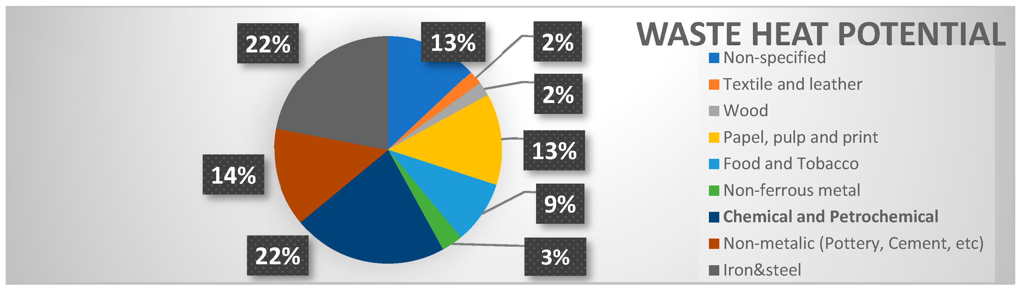
3. Waste Heat Distribution in Manufacturing Industries

Energy-intensive industries (EII) face significant challenges in improving efficiency, maintenance, energy consumption, and sustainability to remain competitive. The industrial Internet of Things (IIoT) has been identified as a key solution for achieving these goals. This large-scale deployment of miniaturized wireless sensor nodes (WSN) will revolutionize the understanding and interaction with complex physical systems.
Each IIoT wireless sensor device requires power between 1.0–100 mW, and batteries are currently the main energy source. A compact, low-cost, and lightweight alternative energy source is needed. A potential solution is energy harvested from industrial waste heat using thermoelectric converters. These EII devices use heat to transform the raw material into products, losing a significant part of its energy. Figure 1 shows waste heat potential in EII [25].
According to waste heat temperature, heat losses are classified into three categories: high (above 400 °C), medium (between 400 °C and 100 °C), and low (below 100 °C). Appropriate waste heat recovery systems are recommended for each temperature range. Based on this classification, an analysis [26] examines the distribution of residual heat by industrial sectors, considering the heat’s origin. In this context, wasted energy is evaluated in terms of Carnot efficiency, where temperature is crucial in determining the residual heat that can be converted into useful work. Table 1 presents the classification of waste heat sources according to their temperature range suitable for our technology.
Combining energy harvesting with IoT technology is ideal for utilizing industrial waste heat to create battery-free, maintenance-free IoT devices. This eliminates the need for lithium batteries, which are explosive and unsuitable for Explosive Atmospheres (ATEX/EX) industries.
Additionally, being heat-powered reduces battery replacement costs and environmental impact. The main challenge in these IoT networks is managing the limited energy stored in super-capacitors and maximizing coverage using mesh networks.

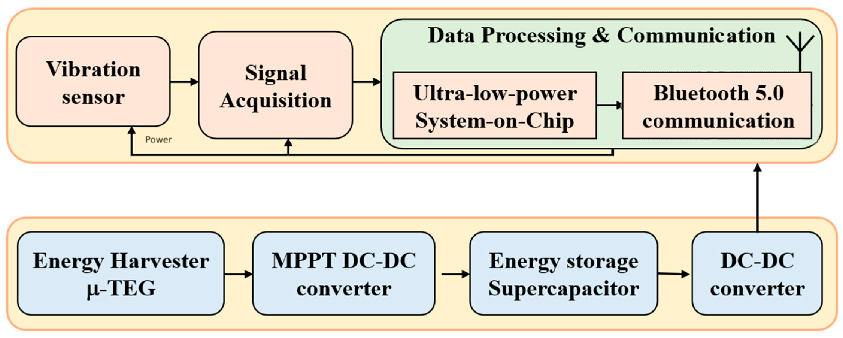
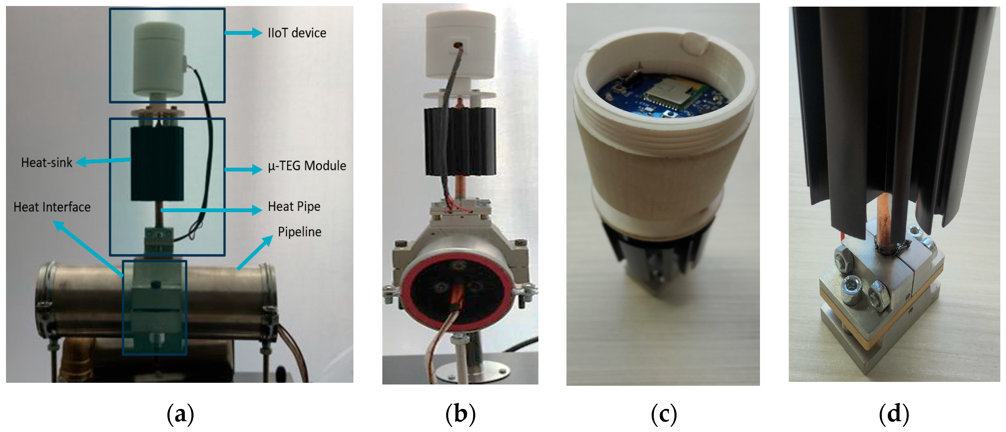
4. Ultra-Low-Power Heat-Powered IoT Platform

Wireless sensor networks require low- to ultra-low power consumption to maximize the energy balance of the power generation/energy storage sub-system. IoT nodes typically operate with low power during processing stages, followed by bursts of high energy use for data transmission [27,28]. This energy profile makes thermoelectric generators (TEG) ideal for powering IoT nodes if there is enough heat in the processes.
Energy can be continuously harvested from facility heat losses and stored. It can then be distributed throughout the IoT node cycle, which includes data acquisition, processing, and transmission stages. Efforts to power IoT nodes are currently being enhanced with algorithms that optimize power consumption in the IoT network and allocate the collected energy to prioritized IoT nodes.
Figure 2 identifies this applicability to industrial facilities. In this case:
  • Energy is harvested using the new TEG thermoelectric generator.
  • The vibration sensor, based on a 3-axis accelerometer with 2 KHz bandwidth, captures accelerations from the electric motor and sends data to the IIoT node using a high-speed wired digital bus (SPI or I2C).
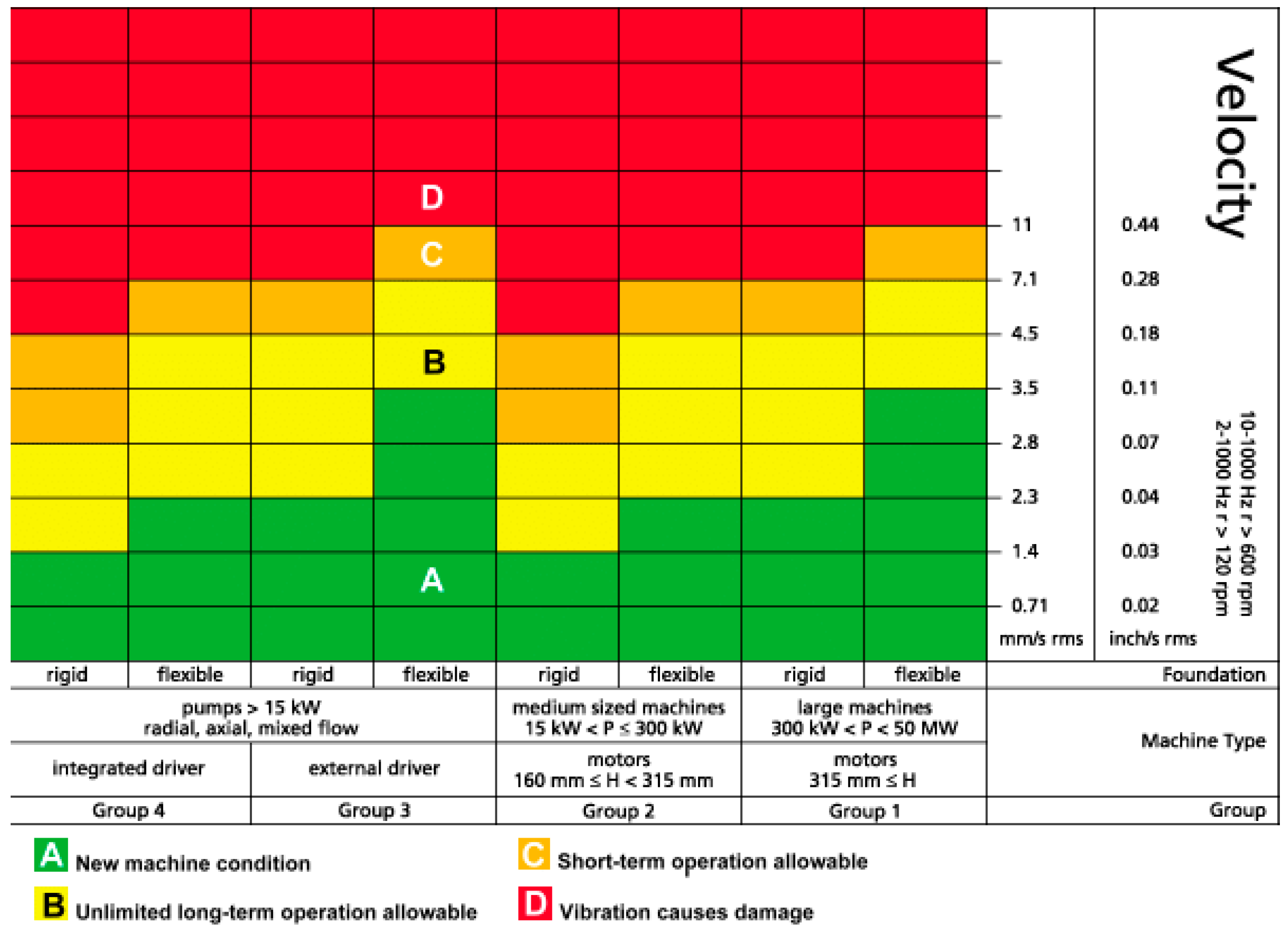
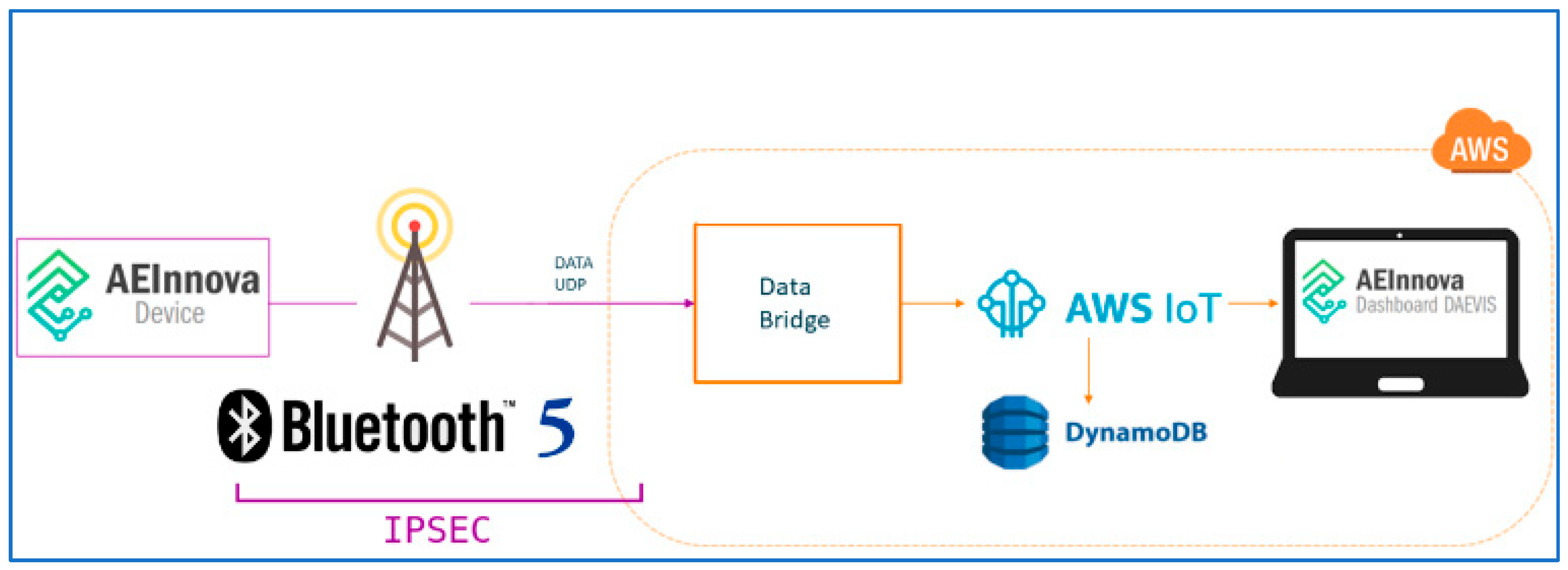
  • The IIoT node detects mechanical vibrations (converting acceleration to velocity) according to ISO 10816 [29] used for predictive maintenance. Data are sent using Bluetooth 5.0, which delivers better performance and immutability concerning previous versions.
  • Data are collected by a Bluetooth gateway and integrated into a cloud dashboard called Daevis (using AWS cloud architecture).
In essence, the all-in-one device that integrates the TEG generator, the vibration sensor and the IoT are shown in Figure 3. The upper section represents the ultra-low power IIOT device that corresponds to the data acquisition channel in a smart sensor. Data, once processed, are sent to the communication channel, either to other nodes that make up the sensor network or to the processor in charge of receiving the data.
The lower channel contains the components used in the energy harvesting module to obtain the supply voltage for the IoT nodes (3.3 V). The energy received by the transducer is rectified, maximized using an MPPT (maximum power point tracker), and regulated to be stored in a supercapacitor. Thus, the IIoT node only is powered when energy is required [30]. The harvesting circuit is responsible for collecting the energy and transforming it to a steady voltage.
The power harvested by a thermoelectric device depends on its ability to keep the cold side at a low temperature while the hot side absorbs high heat. The efficiency of the IoT-WHRS (waste heat recovery system) depends on the ability of the system to collect as much heat as possible while maintaining a significant temperature difference between the two sides. According to thermodynamics, the natural tendency of a TEG is to balance the temperatures of both plates. This occurs through heat dissipation caused by internal thermal resistance, the heat collector, and the heatsink, which plays a crucial role in the system’s overall efficiency. Everything is tightly clamped to minimize gaps in the contact module.

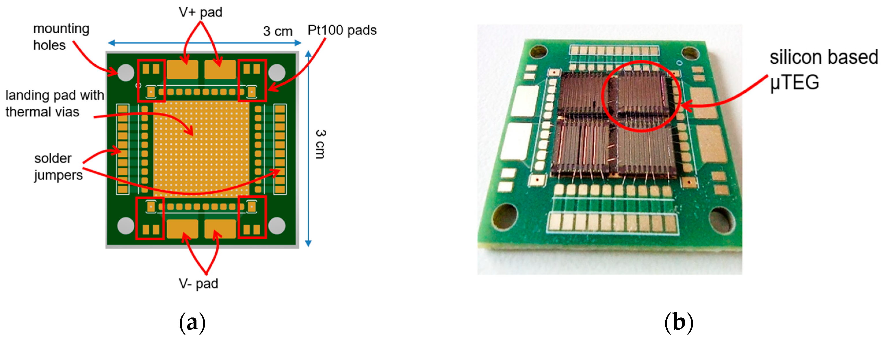
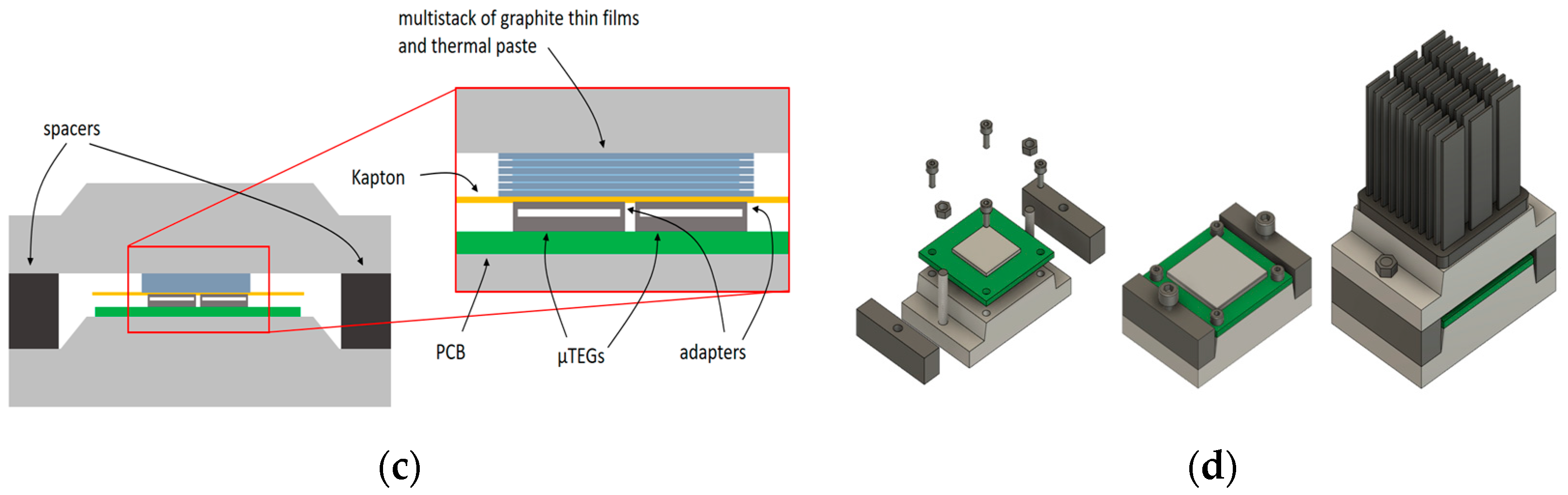
5. Silicon μ-TEG Generator

Thermoelectric energy harvesting technologies and products have been available for decades, but are mostly limited in niche markets, such as space and military applications. The major reasons are:
  • Rare and expensive raw materials. Commercially available TEGs are largely based on Bi2Te3, whereas Te (tellurium) is very rare (rarer than gold) on Earth and is mined in a few countries only.
  • Lack of market standards. Most commercial modules are designed for cooling purposes (Peltier devices in outdoor/mobile coolers connected to 12 V). Vendors and developers often misuse the Peltier module as generation modules (Seebeck effect modules), which leads to unreliable products. The poor quality of those modules made by small producers makes the scenarios for that even worse.
When compared with energy harvesting technologies from other sources, such as vibration (piezoelectric), light (photovoltaics), or electrical-magnetic (radio frequency), the biggest advantage of TEGs is that the energy density is much higher. In near-room-temperature (−20–120 °C) applications, the output of TEGs can be one order of magnitude higher than the other sources. Compared to solar cells, energy harvesting using TEG cells is complementary in usage and application areas.
This paper introduces a new thermoelectric-based material based on one of the most common materials in the earth, silicon. Silicon, in conjunction with germanium, has been used to power deep space missions of the Jet Propulsion Laboratory of Caltech NASA. Space missions launched in 1977 like Voyager I, II, Cassini, New Horizonts or all the Mars’ Robers (Curiosity, Proximity or New Perseverance) are fully Si-Ge-thermoelectrically powered.
In this new approach, a new silicon micro-thermoelectric generator prototype [23] is densely packaged with planar architecture. Optimized boron-doped silicon microbeams with an overall size of 5 × 15 × 15 μm3, thermoelectrically optimized in prior works [30,31], are monolithically integrated into the device.
A PCB housing encapsulates four μ-TEG (Figure 4), with electrical connections to all the available pads via wire bonding. Every device features a total of 10 micro-thermo-couples (μ-TCs) electrically interconnected from each other.
The PCB features a central landing pad for 1.5 × 1.5 cm2 chips covered with thermal vias to improve heat transfer from a hot source below the PCB, several solder jumpers, Pt100 pads and mounting holes (Figure 5).
These improvements boost the overall output powers well within the range of IoT needs (10−100 μW/cm2). Specifically, the μ-TEG on top of a heat source above 200 °C and under still air convection conditions generates more than 14 μW/cm2, quite enough for ultra-low-power IIoT applications.

6. Ultra-Low-Power IoT Device for Predictive Maintenance in Electric Motors

The application selected for verifying the hardware model has been the continuous vibration acquisition of rotative machines (motors, pumps, ventilators, compressors, gearboxes, etc.) for predicting asset maintenance. Applying these techniques, it is possible to improve the level of automation and autonomy of smart facilities reducing the overall maintenance costs of the assets, eliminating breakdowns, downtimes increasing productivity while risks are minimized.
Figure 5 shows the main benefits of Industry 4.0 when they use condition monitoring and predictive maintenance in rotative machine assets. To obtain these benefits, it is important to make a calibrated acquisition of mono- or tri-axial acceleration vibrations of the electric motor and transform this dominium into velocity (mm/s).
For applying these techniques is required to apply the norm ISO 10816 that classifies the severity of a potential machine failure depending on:
  • Type of electric motor (compressor, pump, ventilator).
  • Power of the motor (in KW).
  • Fixation to the ground (rigid or flexible).
In [32] it is possible to deep into this norm that establishes the rules for predictive maintenance. In Figure 6, it is shown an example of pumps. In the figure, the red, yellow, and green regions specify the velocity (mm/s) of the vibration. The higher the velocity of the vibration, the worse for the electric motor.
According to the norm, to monitor industrial processes in quasi-real time, it is important to control all the constraints that guarantee enough energy balance inside the node to attend to data quality demand. In our case, due to the energy generated by a μ-TEG and the overall energy production to monitor the asset being unknown, it is important to consider the following conditions:
  • Subsystem energy storage capacity (mAh).
  • Environmental conditions (temperature and humidity).
  • Power consumption of the electronic components:
    DC/DC converters’ efficiency.
    CPU processors or SoC energy consumption:
    Operation frequency (MHz).
    Energy-saving modes (sleep, ultra-sleep, slow-down, standby).
    Edge computing algorithms.
    Firmware optimization.
    Sensor power consumption.
    Sensing conditioning electronic components (sample and hold, amplifiers, filters, etc.).
    Wireless communication protocols.
    Data rate.
The next subsections present the hardware and firmware systems that minimize the energy balance of the hardware system.

6.1. Power Conversion Module

This module manages the power transformation, and the energy storage subsystem as well as delivering a steady 1.8 V at the output of the module. It uses a highly efficient DC-DC boost converter. The schematic is shown in Figure 7 with the following characteristics:
  • It incorporates a maximum power point tracker (MPPT) from Analog Devices to maximize the V-I μ-TEG production will all the complementary hardware suggested required to operate with TEG devices (left part of the schematic). This device has a cold start voltage of only 15 mV that guarantees to operate with very few ΔT between the μ-TEG sides. This is important due to the low voltage generation of these μ-TEG.
  • It integrates a low-dropout regulator (LDO) to stabilize the output board voltage (right section of the schematic).
  • 6 μ-TEGs are needed to ensure the potential drop required by the system due to its high internal resistivity (associated with 2 series of 3 parallel μ-TEG).
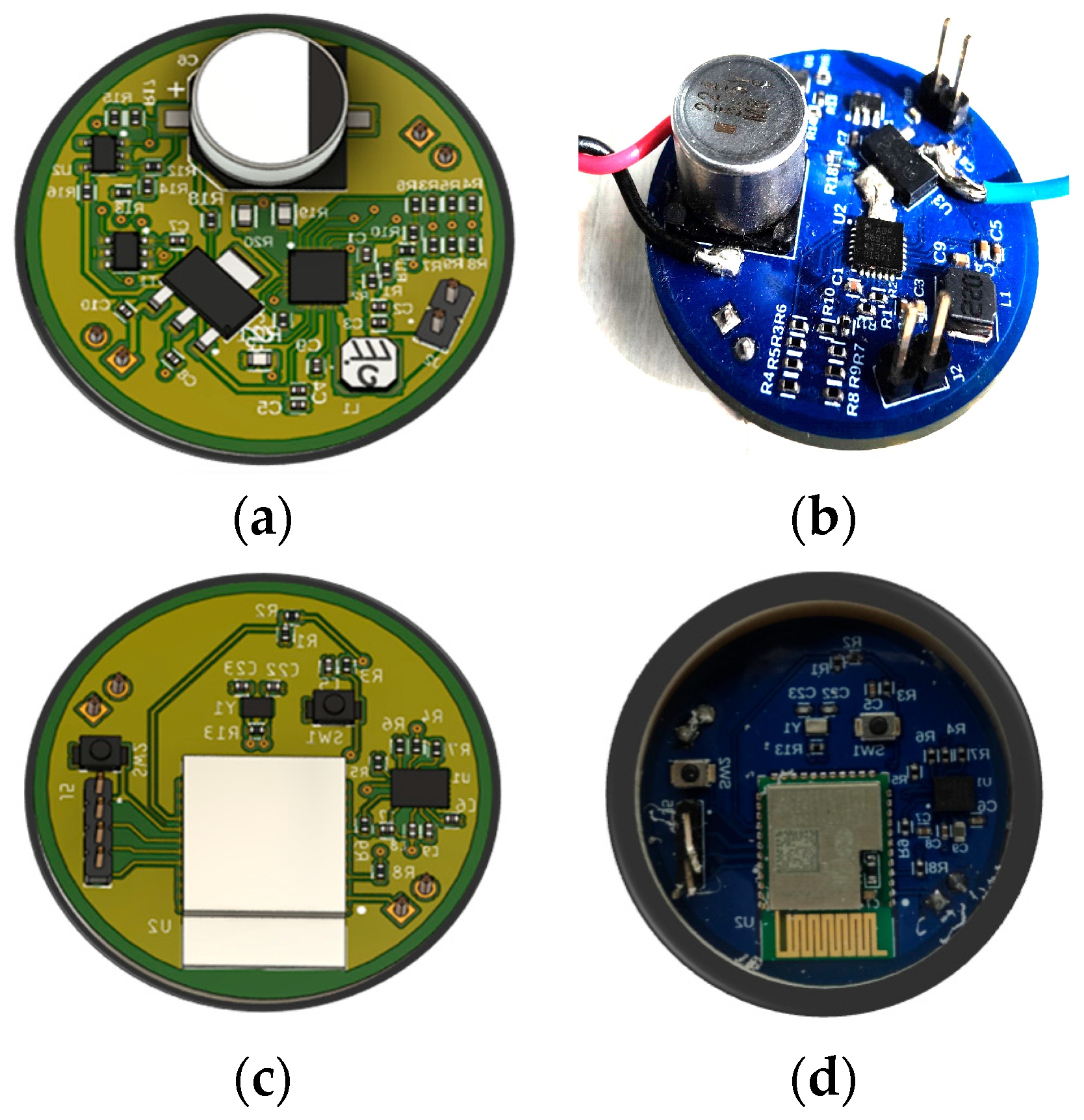
  • The PCB board has an overall diameter of 3.5 cm.

6.2. Processing and Acquisition Platform

This module integrates processing and acquisition circuitry shown in Figure 8. The PCB board is shown in Figure 9c,d with an overall diameter of 3.5 cm. The main subsystems are:
  • A pre-calibrated LSM6DSOX 3D accelerometer/3D gyroscope low-power MEM from ST Microelectronics (Geneva, Switzerland,) with SPI/I2C digital interface. Data are sampled at 2 Ksps. The whole solution (IIOT + thermoelectric device), once built into the all-in-one device, has been calibrated using the Fluke 805 FC vibration meter (Washington, DC, USA).
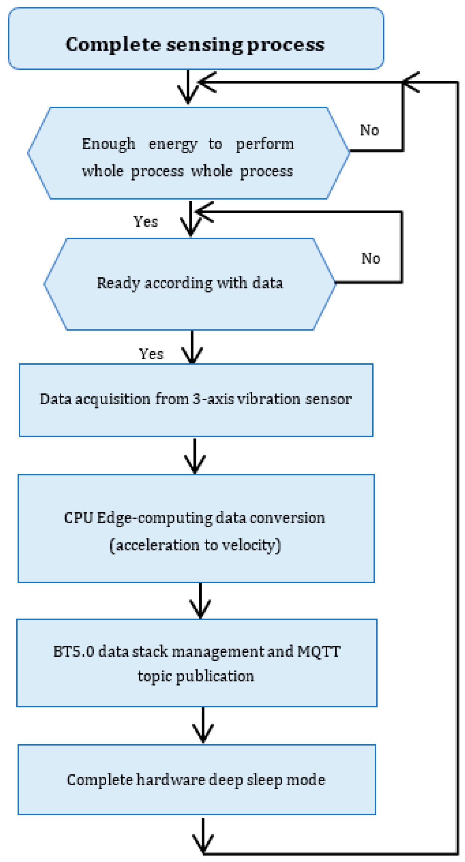
  • Ultra-low-power Infineon (Carinthia, Austria) Cortex M4 BT5.0 processor using. Data are converted from acceleration (g) to velocity (mm/s) which is the magnitude used in the predictive maintenance standard ISO 10816 standard. For this process, we need to integrate the signal in the time domain, but this requires high-level computation for a low-power processor like this M4. An Al alternative process that consumes less energy can be performed in the frequency domain using the following steps:
    • Fourier Transform: First, it is the FFT of the acceleration signal a (t) is taken to obtain A(f), the representation of the signal in the frequency domain. The process involves 1000 frequencies with fast Fourier transformation (FFT) calculus at 2 Ksps (samples per second).
    • Division by j2πf: Integration in the time domain corresponds to dividing by j2πf (where f is frequency) in the frequency domain. This is because differentiating a signal in the time domain corresponds to multiplying by j2πf in the frequency domain, and integration is the inverse operation of differentiation.
      V f = A ( f ) j 2 π f
      Here, V(f) is the Fourier transform of the velocity.
    • Inverse Fourier Transform: Once it has V(f) it is necessary to perform the Inverse Fourier Transform to return to the time domain and obtain the velocity function v (t).
  • Auxiliary components according to the hardware recommendation of both manufacturers.
A state machine is introduced to perform all the acquisition and processing operations. Each state has associated a specific duration and power consumption to control the energy recovery from the device.
Figure 10 shows the algorithm implemented for the whole acquisition and processing process of the control board to perform the measurement and transmission. Data are converted from the acceleration domain to the velocity domain, as requested by ISO 10816 [29].
The system builds a waking-up and deep sleeping-down cycle to meet highly restrictive power generation coming from the µ-TEG. The BT5.0 node modulates signal and publishes all data in the adequate topic of a message-queuing telemetry transport (MQTT) broker deployed inside the IoT core of the Dynamic Aeinnova’s Visualizer (DAEVIS), a complete IoT dashboard fully deployed over Amazon Web Service (AWS in Figure 11). For this process, the MQTT broker has several topics where our device publishes all data, and DAEVIS (the data visualizer) is subscribed to all these topics that are secured using TLS.
Data are easily acquired from the SPI bus. We do not need to incorporate any ADC converter due to the St-Microelectronics IMU having its own ADC, and data can easily be acquired from the I2C or SPI bus depending on the resolution of the data and sps (samples per second) requested from the ADC converter. Potential errors come basically from electromagnetic interferences easily found in these highly noisy industrial environments. For example, it is easy to find more than 100 V/m in heavy industries (iron and steel) where the EMI test standard determines a maximum of only 10 V/m. In this sense, thanks to previous experience in similar projects, it is very difficult to be immune to this noise and the only way to be “partially” immune is to use shielded cables with a lower size of 1.5 m of length.
In the following Figure 11, we show the full process in detail.

7. Experimental Results

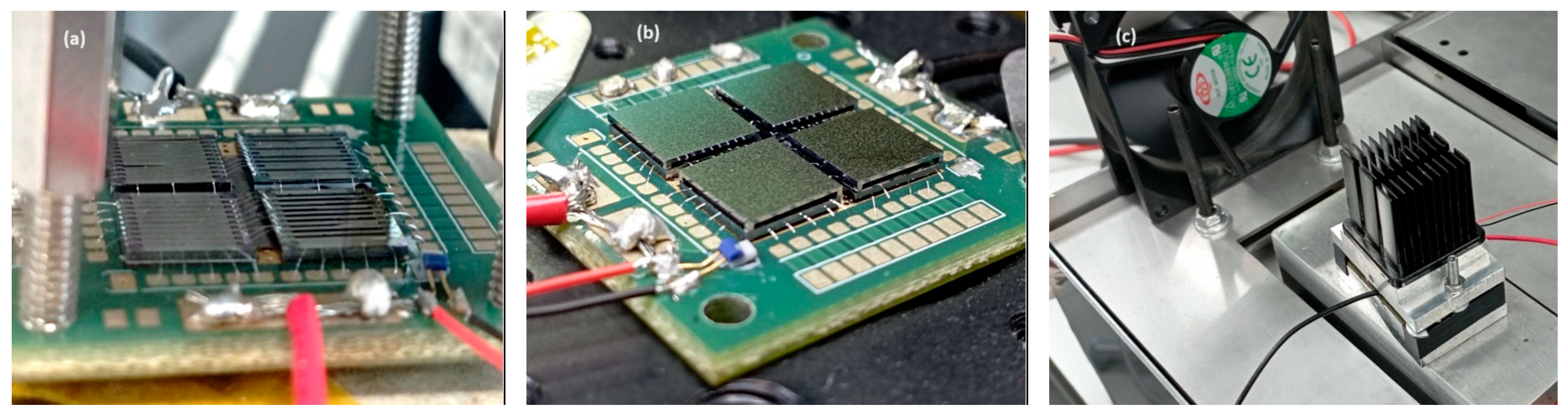
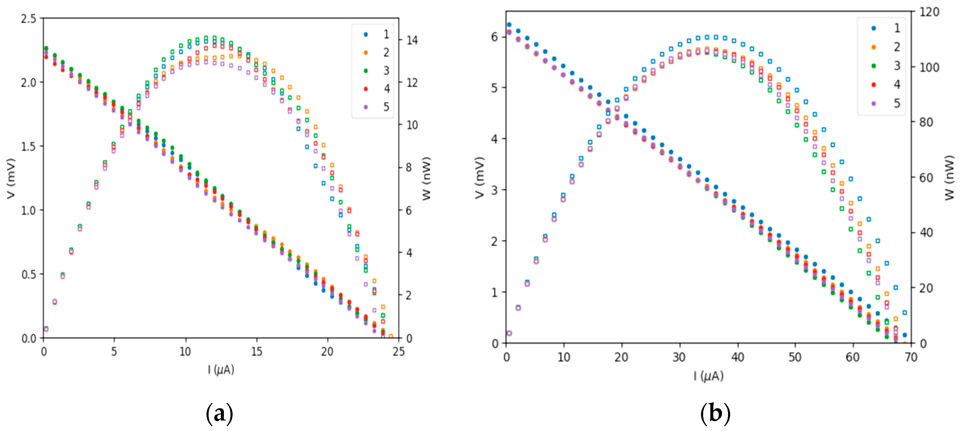
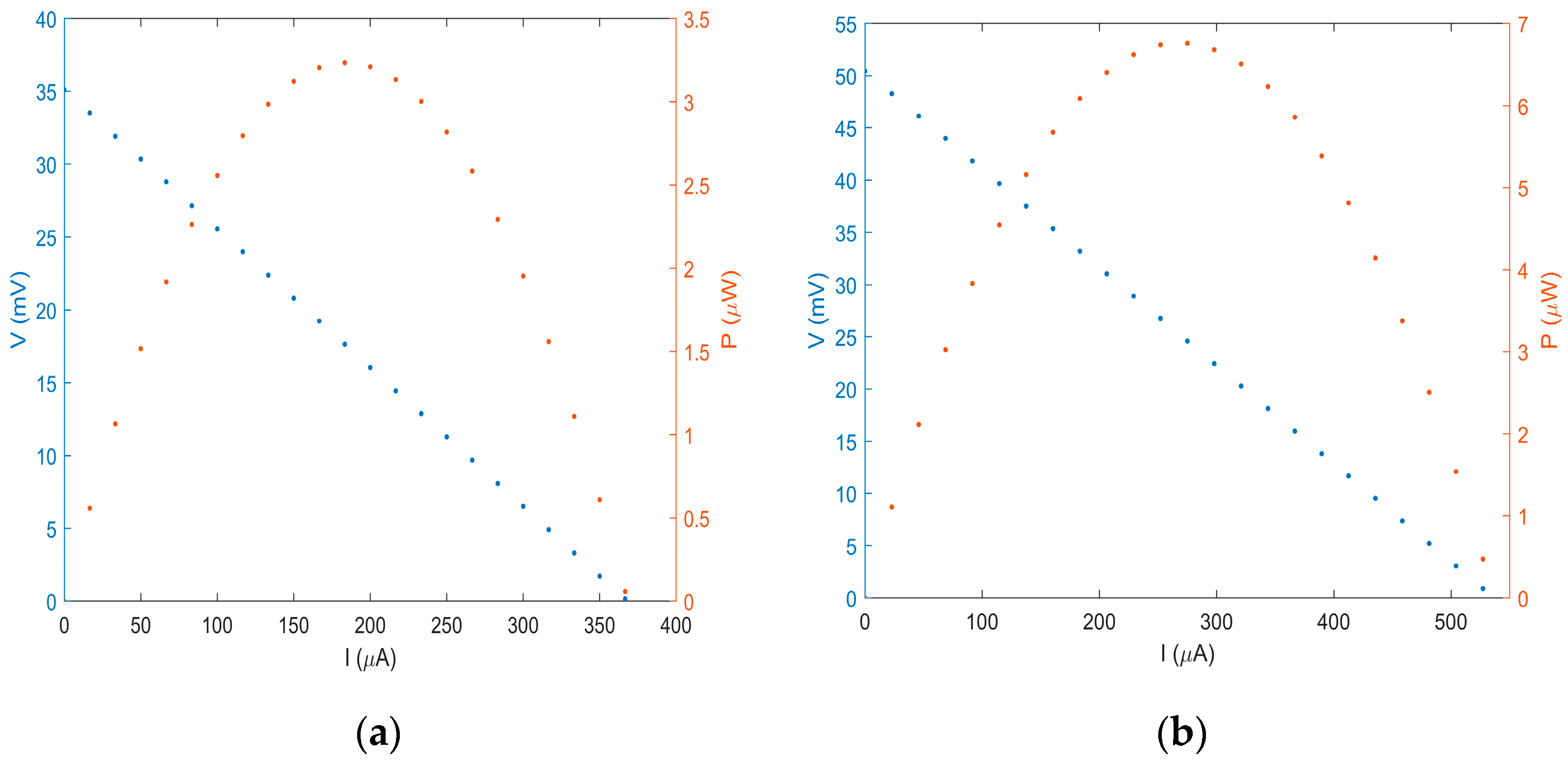
7.1. μ-TEG Module Experiments

The devices have been tested in a controlled environment with a temperature of 25 °C. The system is heated until the collector temperature stabilizes at around four hot ranges—50 °C, 100 °C, 150 °C, and 200 °C—using a controlled PID heater.
During this process, 4 tests have been developed (according to Figure 12). From the bare chip (without any heat exchanger Figure 12a), apply a thermal adapter (Figure 12b), with a heat sink but with forced air cooling (Figure 12c).
A total of five cycles are performed with the bare chip and the bare chip adapter. Results (in Figure 13) with the adapter show significant improvement due to heat transfer to the surroundings.
Figure 14 shows that the incorporation of the heat sink improves the heat transfer and indeed the overall power generation. The best results are achieved with forced air cooling.
As shown in the graphs, there is a significant power generation improvement. The last graph achieves a total power generation of 3.279 μW compared to the left of Figure 12, with only 13.68 nW.
In Table 2, we summarize the power generation with different hot-side temperatures and cooling mechanisms. Values are taken in nW. It is shown in the column (Thot) from 50 °C to 200 °C that the column TP100 is the temperature result obtained from a PT100 sensor integrated into the μ-TEG PCB board.

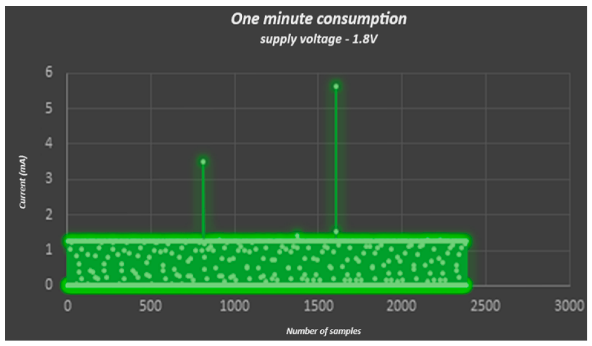
7.2. IIOT Node Experiments

This section analyses the power consumption and the energy management in a complete measurement/processing (in accordance with Figure 10) and using communication of the IIoT node, with a continuous power supply (without the μ-TEG).
The power consumption profile is shown in Figure 15. This is shown in main peaks concerning the data acquisition from the vibration sensor (3.6 mA) and the processing/communication process (5.7 mA).
This device was powered with 1.8 V DC compared to the previous versions that operated at 2.5 V DC, both from AEInnova devices, allowing a significant consumption reduction compared to a previous system operating with LoRaWAN [26] in more than 86%, as shown in Table 3.

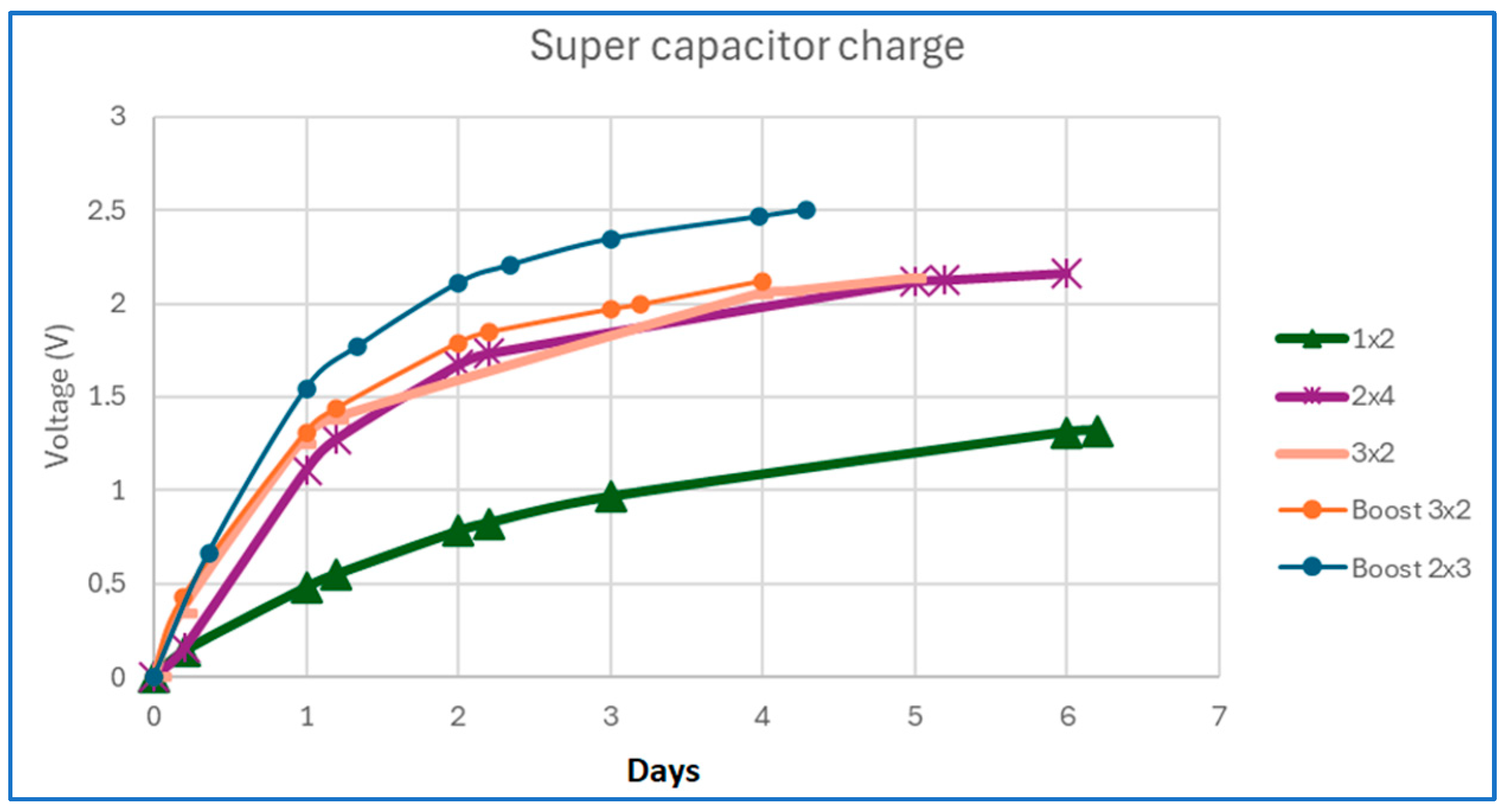
7.3. Whole System Integration

This experiment integrates all the parts (μ-TEG + Bluetooth 5.0 IIoT device) in an all-in-one device as shown in Figure 16. Its sizes are 14 cm in height × 3.8 cm in diameter.
In this new all-in-one device, the μ-TEG thermoelectric module has been redesigned to have adequate thermal coupling to an equivalent industrial pipeline (PID-controlled resistor generating heat). It is composed of the IIoT device module (top), the μ-TEG thermoelectric module (middle), and the clamp to attach the whole device to a heat pipeline.
Due to the geometry of the device, it was not possible to have all subsystems in a single device (TEG–IoT). Therefore, for an equivalent cooling performance to the μ-TEG (Figure 14) and natural performance (Table 2) in locating IIoT devices nearby, a heat pipe was used to transfer the heat to the heat sink (Figure 14b). This redesign installs the IIoT at the top of the whole system without any heat affectation of the power module and processing boards.
Despite the voltage drop due to the high resistance of the μ-TEG (approx. 80 Ω) it has been necessary to change the electric association of μ-TEG modules to achieve the minimum voltage operation of the DC-DC boost converter (15 mV). The best combination has been the association of 6 μ-TEGs, 3 parallels of 2 μ-TEGs in serial, generating enough power to charge the supercapacitor (serial) and reduce the high impedance (parallel).
In this scenario, the supercapacitor requires 10,272 h to have enough voltage to operate. Then, data can be acquired, processed, and transmitted every 28 h thanks to the partial discharging of the supercapacitor being enough to make the low-power processor operate in all subprocesses.
In Figure 17, different associations of μ-TEG have been tested, obtaining the best performance in the combination called (boost 2 × 3). Data is obtained from Table 4.
Possible combinations are:
  • 1 × 2–2 μ-TEG thermogenerator in parallel.
  • 2 × 3–3 parallels of 2 μ-TEG thermogenerators in series each.
  • 2 × 4–4 parallels of 2 μ-TEG thermogenerators in series each.
  • 3 × 2–2 parallel of 3 μ-TEG thermogenerators in series each.
  • Boost: Disabling the internal comparators to generate the hysteresis of activation of the output voltage.

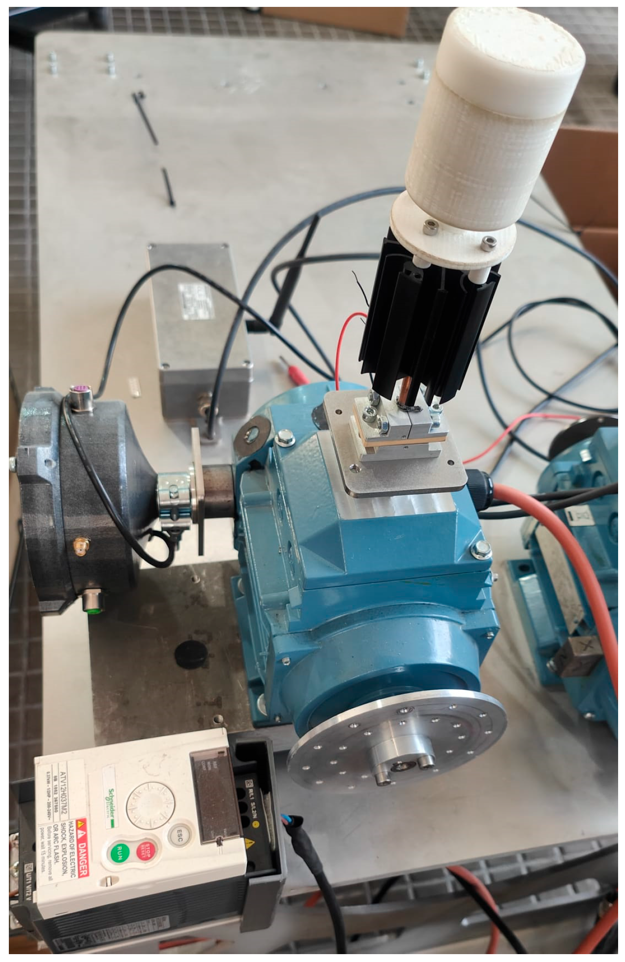
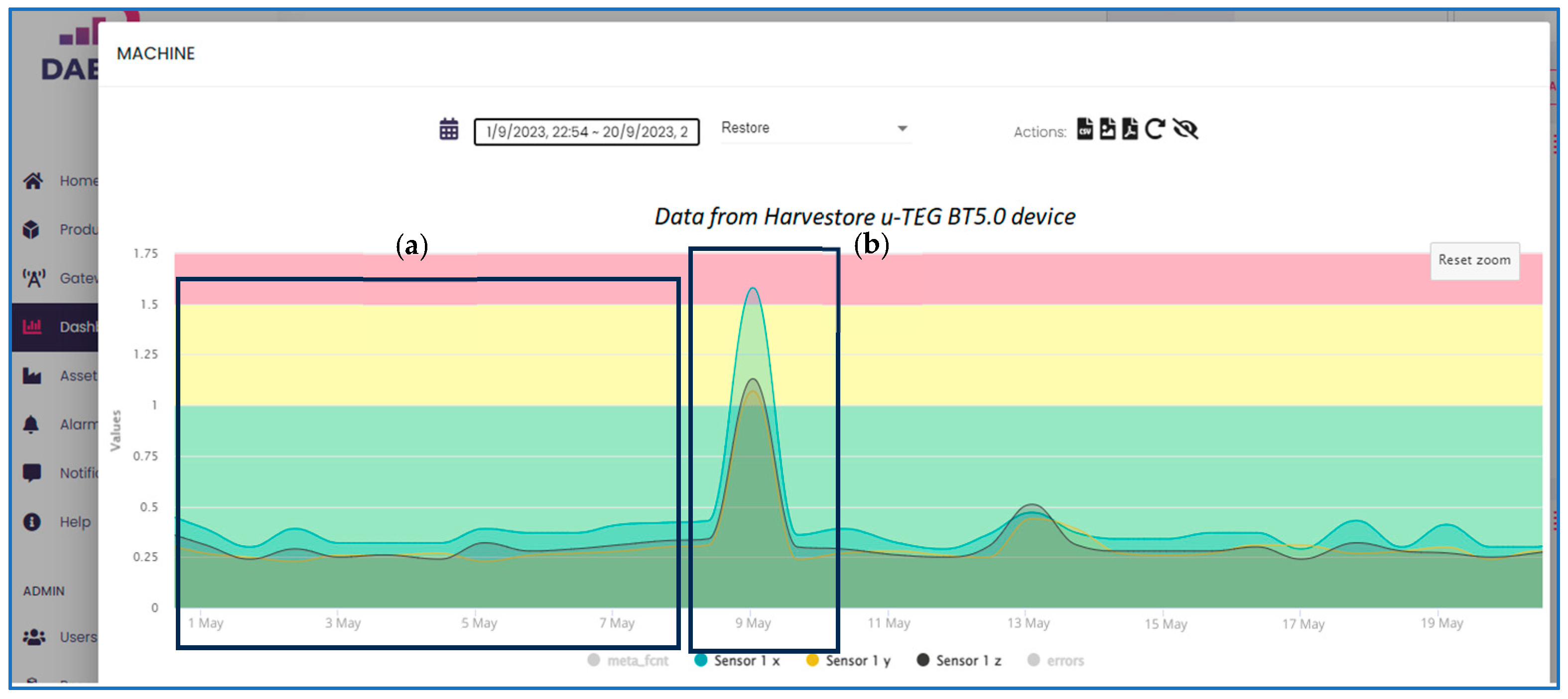
7.4. Monitoring Vibrations in a Laboratory Motor

Figure 18 presents the proof of concept deployed in AEInnova’s laboratory to demonstrate the full application of the system. The system allows us to test the complete edge computing and heat-powered module in a real environment with data in Figure 19.
The system uses the μ-TEG attached to a hot surface of the motor, the IIoT communication device and a 3-axis vibration sensor installed in the same board, capturing vibrations of the rotative machine to monitor (a 350 W conventional motor). Finally, a Bluetooth 5.0 gateway sends data packets to the IoT core located in DAEVIS, a cloud platform developed under Amazon Web Services.
Figure 19 shows the registration of the three-axis vibrations for 20 days, which is from the first tests in our laboratory. Two time slots are considered, according to:
  • No misalignment (window a).
  • Misalignment (window b). Small counterweight in the rotor of 10 g.
According to ISO 10816 this motor is classified as Machine Group 4, with a rigid base on the ground. From the data obtained, the health of the machine can be known according to the ISO Standard, which defines the critical speeds as:
  • Healthy machine: From 0 mm/s to 1 mm/s.
  • Short-term operation allowable: From 1 mm/s to 1.5 mm/s.
  • Vibrations cause machine damage: From 1.5 mm/s to unlimited.
The figure shows that there are several fractions of time in days 2, 3, and 4, which significantly exceed the damaging values of 4.5 mm/s, meaning that this machine requires rapid maintenance to avoid critical damage.

7.5. Economic Model and Competitor’s Comparison

In this subsection, we conducted a comprehensive comparison of key competitors in the industry that offer similar devices for predictive maintenance (Table 5). The main factors considered in the comparison include price, wireless communication technology, energy source, accelerometer bandwidth, the number of accelerometer axes, and overall device size.
To summarize, the most commonly used wireless industrial protocol is WirelessHART, typically powered by a lithium battery (with the exception of the Fluke 3562 by Everactive, AEInnova InduEye Vibro, and this project). Most devices feature a three-axis accelerometer with bandwidths of up to 1 KHz, except for the EMERSON AMS and ACOEM Defender, which offer up to 20 KHz and 6 KHz bandwidth on the Z-axis, respectively

8. Conclusions

The work presents a new ultra-low heat-powered predictive maintenance solution to monitor vibrations in heat-intensity facilities.
A new silicon thermoelectric microgenerator has been integrated into a fully self-powered IIoT solution to monitor 3-axis vibration of rotative motors according to the standard ISO 10816. Additionally, an ultra-low-power IoT device has been completely redesigned to be powered with a low-power generation µ-TEG.
The main benefits offered by this thermal harvester device are clear: IoT devices can be powered by harvested energy without the need to use other energy. These IoT nodes can be installed anywhere without the need to use a power grid or batteries [33], and devices may operate in critical facilities where an electrical power supply is not recommended. Additionally, complies with the new EU regulations (12 July 2023) of battery usage in any device [34].
The methodology followed in this paper is generic and can be standardized for any IoT-WHRS architecture.
The power electronics as well as acquisition and processing circuits developed for this project have reduced consumption by 49.6% during sleep mode, where the node remains most of the time, and achieved a reduction of 86% during transmission.
With these electronics, the IoT device can operate from 150 °C, as justified previously, sending information every 28 h. The first charge of the capacitor will take 4 days.
Additionally, the DC/DC converter efficiency has achieved an accepted value of 50%, the 6 cells will generate about 4 μW, which implies a current of 2 μA.
Although the thermogenerator module was assembled with 4 μTEG, and it will be necessary to use 6 thermogenerators for the system to work, 24 μ-TEG could be integrated, reducing the complexity of the system.
The whole system has been developed to achieve TRL4-5. It has been tested in controlled laboratory conditions but is easily scalable to operate in real industrial conditions. It has been taken into account hardware limitations to operate in ATEX/IECEX explosive environment and for easy passing EMIs. Hardware enclosure design would need to be improved to pass corrosion tests highly required in several industries (chemical, petrochemical, biogas plants, etc.).
Additionally, an in-depth comparison has been conducted, examining the key characteristics of the current products available on the market. Most wireless solutions utilize WirelessHART as their communication protocol and rely on lithium batteries as their primary energy source, with the exception of Fluke’s Everactive, which is also powered by heat.
As the European H2020 FET Proactive project Harvestore concluded in June 2024, it becomes evident that waste-heat-powered devices for energy-intensive industries, though still in their early stages with limited market availability, hold significant promise. Battery-powered devices have seen low adoption in these industries due to their vulnerability to heat, explosion risks, and inability to operate in ATEX environments due to the lack of explosive certifications.
In particular, energy-intensive industries such as iron, steel, aluminium, copper, cement, glass, paper, chemical, petrochemical, and oil and gas have large facilities with low levels of automation for monitoring non-critical assets. This is largely due to the high costs associated with wired sensing solutions or the frequent battery replacements required for alternative wireless solutions, which are often affected by heat. Although μ-TEG generates low power, limiting its potential applications, Bi2Te3-powered IIoT devices, available from companies like AEInnova and Fluke, show strong potential for market growth.

Author Contributions

Conceptualization, R.A., F.B., L.F., A.T. and C.F.; Methodology, R.A., J.O., M.S., L.F., A.T., A.M. and C.F.; Software, R.M.; Validation, R.A., J.O., A.M., F.B. and C.F.; Investigation, R.A., R.M., J.O., A.P., D.M., M.S., A.R.-I., A.M., F.B. and C.F.; Resources, R.A., J.O., A.P., D.M., M.S., A.R.-I., A.M., F.B. and C.F.; Writing—original draft, R.A.; Writing—review & editing, R.A. and J.O.; Supervision, C.F.; Funding acquisition, R.A., L.F., A.T. and C.F. All authors have read and agreed to the published version of the manuscript.

Funding

This investigation was supported by the European Commission H2020 FET Proactive Harvestore Project under grant 824072. This investigation was supported by the European Commission H2020 EIC Pilot Project InduEye 2.0 under grant 946845. This investigation was supported by the Spanish Ministry of Education through the FPU grant FPU18/01494, and by the University and Research Secretary of the Business and Knowledge Department of the Generalitat de Catalunya in the project FEM-IoT (001-P-001662). This work acknowledges the financial support from the Agència de Gestió d’Ajuts Universitaris i de Recerca (AGAUR) of the Generalitat de Catalunya (2021 SGR 00497 & 2021 SGR 10623). This research was also supported by the Spanish National Research Agency (AEI) through the project PID2019-110142RBC21 (AEI/FEDER, EU) THERMOLOGICS. This research used the Spanish ICTS Network MICRONANOFABS, partially funded by FEDER funds through MINATEC-PLUS-2 project FICTS2019-02-40. This research was also supported by the Spanish National Research Agency (AEI) through the project PID2020-116890RB-I00 (AEI/FEDER, EU) WISE. Support through the Maria de Maeztu grant CEX2023- 001397-M, funded by MICIU/AEI/10.13039/501100011033.

Institutional Review Board Statement

Not applicable.

Informed Consent Statement

Not applicable.

Data Availability Statement

The original contributions presented in the study are included in the article, further inquiries can be directed to the corresponding author.

Conflicts of Interest

Authors Raúl Aragonés, Roger Malet, Alex Prim and Denis Mascarell were employed by the company Alternative Energy Innovations, S.L.—AEInnova. The remaining authors declare that the research was conducted in the absence of any commercial or financial relationships that could be construed as a potential conflict of interest.

References

  1. Galov, N. How Many IoT Devices Are There in 2020? [All You Need To Know]. Techjury, 2 June 2022. [Google Scholar]
  2. Pirson, T.; Bol, D. Assessing the embodied carbon footprint of IoT edge devices with a bottom-up life-cycle approach. J. Clean. Prod. 2021, 322, 128966. [Google Scholar] [CrossRef]
  3. Alegret, R.N.; Aragonés, R.; Oliver, J.; Ferrer, C. Exploring IIoT and Energy Harvesting Boundaries. In Proceedings of the IECON 2019-45th Annual Conference of the IEEE Industrial Electronics Society, Lisbon, Portugal, 14–17 October 2019. [Google Scholar]
  4. Ahmad, S. The Lithium Triangle: Where Chile, Argentina, and Bolivia Meet. Harv. Int. Rev. 2020, 41, 51–53. [Google Scholar]
  5. Campbell, M. Los Campos de Litio en Sudamérica Revelan el Lado Oscuro de Nuestro Futuro “Verde”. Euronews, 3 February 2022. [Google Scholar]
  6. Etchegaray, Á. China Se Está Convirtiendo en la Fábrica de Baterías del Mundo. SupChina, 4 April 2021. [Google Scholar]
  7. CirbaSolutions. Recycling Benefits. 2022. Available online: https://www.cirbasolutions.com/learning-center/recycling-benefits/ (accessed on 4 April 2024).
  8. Maddikunta, P.K.R.; Srivastava, G.; Gadekallu, T.R.; Deepa, N.; Boopathy, P. Predictive model for battery life in IoT networks. IET Intell. Transp. Syst. 2020, 14, 1388–1395. [Google Scholar] [CrossRef]
  9. Vermesan, O.; Friess, P. Internet of Things-From Research and Innovation to Market Deployment; River Publishers: Aalborg, Denmark, 2014. [Google Scholar]
  10. Bell, L.E. Cooling, Heating, Generating Power, and Recovering Waste. Heat with Thermoelectric Systems. Science 2008, 321, 1457–1461. [Google Scholar] [CrossRef] [PubMed]
  11. Markiewicz, M.; Dziurdzia, P.; Skotnicki, T. Randomly moving thermoelectric energy harvester for wearables and industrial Internet of Things. Nano Energy 2024, 126, 109565. [Google Scholar] [CrossRef]
  12. EMERSON. Power Module Life Estimator. Available online: https://tools.measurementinstrumentation.com/pervasive-sensing/power-module-life-estimator/products/12/instrument-type/21/result/ (accessed on 17 June 2024).
  13. Beretta, D.; Neophytou, N.; Hodges, J.M.; Kanatzidis, M.G.; Narducci, D.; Martin-Gonzalez, M.; Beekman, M.; Balke, B.; Cerretti, G.; Tremel, W.; et al. Thermoelectrics: From history, a window to the future. Mater. Sci. Eng. R. Rep. 2019, 138, 210–255. [Google Scholar] [CrossRef]
  14. Zhang, Q.; Deng, K.; Wilkens, L.; Reith, H.; Nielsch, K. Microthermoelectric devices. Nat. Electron. 2022, 5, 333–347. [Google Scholar] [CrossRef]
  15. TRECOM Technical Report 63–17. Optimization of Silicon-Germanium Thermoelectric Modules for Transportation Corps Silent Boat Design. 1963. Available online: https://apps.dtic.mil/sti/citations/AD0412341 (accessed on 24 May 2024).
  16. Fortin, R.C. Fabrication of One Silicon-Germanium Thermoelectric Test Unit. Final Report Prepared by the Radio Corporation of America for the Jet Propulsion Laboratory. 31 August 1965. Available online: https://ntrs.nasa.gov/citations/19660004360 (accessed on 21 February 2024).
  17. Gordillo, J.M.S.; Morata, A.; Sierra, C.D.; Salleras, M.; Fonseca, L.; Tarancón, A. Recent advances in silicon-based nanostructures for thermoelectric applications. APL Mater. 2023, 11, 040702. [Google Scholar] [CrossRef]
  18. Harvestore. European Commission H2020 FET Proactive Project. Available online: www.harvestore.eu (accessed on 10 June 2020).
  19. Kumar, A.; Verma, R. Energy Harvesting Techniques for Self-Powered Electronics: State-of-the-Art and Challenges. J. Adv. Res. Electron. Eng. Technol. 2023, 10, 6. [Google Scholar]
  20. Yildiz, F. Potential Ambient Energy-Harvesting Sources and Techniques. J. Technol. Stud. 2009, 35, 40–48. [Google Scholar] [CrossRef]
  21. De Mil, P.; Jooris, B.; Tytgat, L.; Moerman, I. Design and Implementation of a Generic Energy-Harvesting Framework Applied to the Evaluation of a Large-Scale Electronic Shelf-Labeling Wireless Sensor Network. EURASIP J. Wirel. Commun. Netw. 2010, 2010, 343690. [Google Scholar] [CrossRef]
  22. Adu-Manu, K.S.; Adam, N.; Tapparello, C.; Ayatollahi, H.; Heinzelman, W. Energy-Harvesting Wireless Sensor Networks (EH-WSNs): A Review. ACM Trans. Sens. Netw. 2018, 14, 2. [Google Scholar] [CrossRef]
  23. Ali, A.; Shaukat, H.; Bibi, S.; Altabey, W.A.; Noori, M.; Kouritem, S.A. Recent Progress in Energy Harvesting Systems for Wearable Technology. Energy Strategy Rev. 2023, 49, 101124. [Google Scholar] [CrossRef]
  24. White, N.M.; Zaghari, B. Energy Harvesting: An Overview of Techniques for Use within the Transport Industry. IEEE Electr. Insul. Mag. 2022, 28, 24–32. [Google Scholar] [CrossRef]
  25. Oak Ridge National Lab. Waste Heat to Power Market Assessment. Available online: https://info.ornl.gov/sites/publications/Files/Pub52953.pdf (accessed on 10 October 2023).
  26. Bianchi, G.; Panayiotou, G.P.; Aresti, L.; Kalogirou, S.A.; Florides, G.A.; Tsamos, K.; Tassou, S.A.; Christodoulides, P. Estimating the waste heat recovery in the European Union Industry. Energy Ecol. Environ. 2019, 4, 211–221. [Google Scholar] [CrossRef]
  27. Sanislav, T.; Mois, G.D.; Zeadally, S.; Folea, S.C. Energy harvesting techniques for internet of things (IoT). IEEE Access 2021, 9, 39530–39549. [Google Scholar] [CrossRef]
  28. Zeadally, S.; Shaikh, F.K.; Talpur, A.; Sheng, Q.Z. Design architectures for energy harvesting in the Internet of Things. Renew. Sustain. Energy Rev. 2020, 128, 109901. [Google Scholar] [CrossRef]
  29. ISO 10816-8:2014; Mechanical Vibration—Evaluation of Machine Vibration by Measurements on Non-Rotating Parts. International Organization for Standardization: Geneva, Switzerland, 2014.
  30. Sojo-Gordillo, J.M.; Estrada-Wiese, D.; Duque-Sierra, C.; Diez, G.G.; Salleras, M.; Fonseca, L.; Morata, A.; Tarancón, A. Tuning the Thermoelectric properties of boron-doped silicon nanowires integrated into a micro-harvester. Adv. Mater. Technol. 2022, 7, 2101715. [Google Scholar] [CrossRef]
  31. Gordillo, J.M.S.; Diez, G.G.; Pujad, M.P.; Salleras, M.; Dolcet, M.; Fonseca, L.; Morata, A.A. Tarancón, Thermal conductivity of individual Si and SiGe epitaxially integrated NWs by scanning thermal microscopy. Nanoscale 2021, 13, 7252–7265. [Google Scholar] [CrossRef] [PubMed]
  32. Wais, M. ISO 10816 Condition Monitoring And Machinery Protection Systems. 2022. Available online: https://www.researchgate.net/publication/360973708_ISO_10816_CONDITION_MONITORING_AND_MACHINERY_PROTECTION_SYSTEMS (accessed on 7 June 2023).
  33. Aragones Ortiz, R.; Oliver Parera, M.; Malet Munte, R.; Marquez Garda, M.T.; Comellas Vogel, D. Vibration and Steam Leaks Monitoring Using a Batteryless IIoT Powered by Waste Heat Using LoRaWAN Wireless Protocol in Chemical Plants. In Proceedings of the ADIPEC, Abu Dhabi, United Arab Emirates, 31 October–3 November 2022. [Google Scholar] [CrossRef]
  34. European Commission. Ensuring that Batteries Placed on the EU Market Are Sustainable and Circular throughout Their Whole Life Cycle. Available online: https://environment.ec.europa.eu/topics/waste-and-recycling/batteries_en (accessed on 25 June 2024).
Figure 1. Waste heat potential per industrial sector in % (EU) [9].
Information 15 00545 g001
Figure 2. Application of the solution for measuring vibrations in a rotative machine.
Information 15 00545 g002
Figure 3. Energy-harvesting architecture in IoT nodes, from the EH to the sensor and transmitter.
Information 15 00545 g003
Figure 4. (a) μ-TEG PCB housing. (b) μ-TEG correctly bounded. (c,d) Coupling the heat sink to achieve the maximum ΔT.
Information 15 00545 g004aInformation 15 00545 g004b
Figure 5. Predictive maintenance savings in electric machines.
Information 15 00545 g005
Figure 6. ISO-10816 applied for a pump.
Information 15 00545 g006
Figure 7. Power conversion module schematic.
Information 15 00545 g007
Figure 8. Acquisition and control board.
Information 15 00545 g008
Figure 9. (a,b): Power conversion module rendered and real. (c,d): Control board module rendered and real.
Information 15 00545 g009
Figure 10. Complete sensing algorithm from the acquisition to the processing and communication.
Information 15 00545 g010
Figure 11. Complete AWS deployment for data visualization.
Information 15 00545 g011
Figure 12. Testing setup with several levels of cooling. From raw (a), with heat exchanger (b) to forced air cooling (c).
Information 15 00545 g012
Figure 13. Results of the performance test. Bare chip cooling (a). With thermal adapter (b).
Information 15 00545 g013
Figure 14. Results of the performance test. With a heat sink natural convection (a). With forced air cooling (b).
Information 15 00545 g014
Figure 15. Results of the μ-TEG’s performance test for this assay.
Information 15 00545 g015
Figure 16. All-in-one integration with different perspectives. From the whole device (a), front profile (b), top overview (c) to the heat pipe integration (d).
Information 15 00545 g016
Figure 17. Supercapacitor charges depend on the μ-TEG association.
Information 15 00545 g017
Figure 18. PoC monitoring vibrations of a 350 W AC motor with different levels of misalignments.
Information 15 00545 g018
Figure 19. Test with different misalignments (a) without and (b) major.
Information 15 00545 g019
Table 1. Temperature ranges in common industrial processes.
Temperature RangeIndustrial Use CaseTemperature (°C)
230–590 °CSteam boiler exhaust230–480
Gas turbine exhaust370–540
Reciprocating engine exhaust320–590
Heat treating furnace Drying & baking ovens430–650
Cement Kiln230–590
<230 °CExhaust gases exiting recovery devices in gas-fired boilers, ethylene furnaces, etc.70–230
Process steam condensate Cooling water from:50–90
Drying, baking, and curing ovens70–120
Hot processed liquids/solids90–230
Table 2. Power generation in nW with several kinds of cooling mechanisms.
Thot (°C)TPt100 (°C)BareAdapterNaturalForced
5047–430.16413.9650.27149.7
10087–801.94815.42426.41033
150130–1206.64949.4113413064
200172–16013.68106.232336767
Table 3. Power consumption of the Bluetooth 5.0 and LoRa versions.
DescriptionAEInnova’s LoRa ChipsetAEInnova’s Bluetooth 5 Chipset
Voltage supply2.5 V1.8 V
Supply current Sleep mode1 mA0.7 μA
Supply current Idle mode12 mA2.2 μA
Supply current in processing/transmission mode.42 mA5.7 mA
Table 4. Time to charge supercapacitor to operate.
μ-TEG
Configuration
1 × 22 × 43 × 2Boost 3 × 2Boost 2 × 3
Days of ChargingVDaysVDaysVDaysVDaysV
0000000000
0.20.140.20.15770.170.34190.190.42630.360.666
10.4811.1090.951.24611.31211.547
1.20.54991.21.2751.161.3811.21.4381.341.773
20.78121.6723.962.0521.78822.111
2.20.8242.21.7324.162.0642.21.8442.342.206
30.96552.1174.9572.13431.96732.347
61.315.22.126 3.21.9933.982.466
6.21.3262.163 42.1184.292.504
Table 5. The competitor’s comparison—battery-powered and heat-powered.
Brand-ModelPriceWireless TechEnergy SourceBW/AxisSize (mm)
This project600$Bluetooth 5.0Heat1 KHz/3140 × 8 Ø
AEInnova InduEye Vibro (Barcelona, Spain)1200$LoRaWANHeat1 KHz/3Sensor: 48 × 48 × 37
TEG mod: 130 × 75 × 60
Fluke 3562 (Wasington, USA)2 Nodes + GW = 3500$.Proprietary GHz.Heat1 KHz/3Sensor: 53 × 48 × 81
TEG mod: 74 × 58 × 36
Emerson AMS (Missouri, USA)1600$WirelessHARTBatteryX-Y 1 KHz
Z-20 KHz/3
152 × 44 Ø
SKF Vibration (Gothenburg, Sweden)900$WirelessHARTBattery1 KHz/166
Acoem Defender (Paris, France)2500$Wifi 802.11BatteryZ: 15 KHz.
X-Y: 6 KHz/3
100 × 35
Yokogawa Sushi (Tokyo, Japan)700$LoRaWANBattery1 KHz/3166 × 42 Ø
ABB Wimon 100 (Zürich, Switzerland)1400$WirelessHartBattery.1 KHz/311 × 32 Ø
Disclaimer/Publisher’s Note: The statements, opinions and data contained in all publications are solely those of the individual author(s) and contributor(s) and not of MDPI and/or the editor(s). MDPI and/or the editor(s) disclaim responsibility for any injury to people or property resulting from any ideas, methods, instructions or products referred to in the content.

