Abstract
This paper deals with the issues of computation of the nonlinear load harmonic currents in the presence of external distortions based on the real measurements with help of passive harmonic. Such values are necessary when modeling an equivalent nonlinear load as current sources in the presence of external distortions. The passive filter allows to separate external and internal distortions, which is necessary when determining the harmonic currents of a single consumer. The influence of various parameters on the computation of harmonic currents of a nonlinear load, such as the parameters of a passive harmonic filter, the impedance of the power supply transformer, the load parameters of the consumer, taking into account the harmonic generation from the grid side, and from the consumer side, is considered. It is shown that an external source of distortion has practically no effect on the error in estimating the harmonic current magnitudes of a nonlinear load. The obtained simulation results were confirmed experimentally on a laboratory test bench. Recommendations for the selection of passive harmonic filter parameters have been developed to minimize the error in determining the harmonic current magnitudes of a nonlinear load.
1. Introduction
A large number of nonlinear consumers are connected to modern electrical grids [1]. Such installations include semiconductor rectifiers [2], arc furnaces [3], controlled and uncontrolled power converters [4], LED lighting systems [5], etc. The operation of such devices leads to the occurrence of harmonics in current and voltage [6]. Harmonic currents flow through power lines and transformers, causing a non-sinusoidal voltage drop, thereby degrading the power quality [7]. It is necessary to calculate the operating modes of the consumers and grids with degraded power quality indicators in order to determine the parameters of harmonic reduction devices [8], to predict power quality indicators depending on load parameters [9], determine negative impact of distortions on electrical equipment [10], determine power losses [11], etc. The correctness of such operating modes modeling in many respects is determined by the accepted model of nonlinear load [12,13].
There are various models of nonlinear electrical loads, which can generally be classified into simulation models based on models of semiconductor elements being a part of them [14,15,16]; in the form of current sources at harmonic frequencies [17,18,19]; in the form of volt-ampere characteristics obtained by approximation according to various equations [20,21,22]; in the form of nonlinear impedances [23,24,25]; based on time-domain, frequency-domain, or time-frequency modeling approaches [26,27,28,29].
Various approaches are proposed to determine the parameters of a nonlinear load for simulation from real measured data [30,31,32]. In [31], an approach and modeling algorithm were proposed, based on the measured harmonic parameters in the electrical nodes with nonlinear loads, which make it possible to represent nonlinear loads as a set of distribution functions of harmonic currents.
In some works [18,24], when modeling a nonlinear load as current sources, expressions are presented for determining the harmonic current magnitudes depending on the type of load. Among them are three-phase uncontrolled rectifiers, controlled rectifiers, variable frequency drives, thyristor power controllers, etc.
In a number of papers, it is proposed to determine the parameters of inverters and rectifiers based on various methods, such as time-frequency analysis technique [33,34], periodogram technique [35,36], and machine learning algorithm [37,38]. Basically, such an analysis is carried out for the classification and localization of nonlinear loads [39,40].
Traditional nonlinear load models in the form of current sources are suitable for simplified computations in the presence of harmonics. In this case, the magnitude values of current sources for different frequencies are set by simplified expressions, where the harmonic current magnitude at the fundamental frequency is divided by the harmonic order. The obtained magnitude values differ significantly from the real measured data [41,42,43]. In this case, the parameters of the energy system and equipment loading are not taken into account.
The impact of equipment loading on the harmonic current magnitudes of the fifth and seventh harmonic order (h5, h7) can be estimated from the data in Figure 1. Experimental measurements of current waveforms of adjustable-speed induction motor drives were carried out. The power of electric drives at rated load corresponded to the following values: P1 (100%) = 3 kW, P2 (100%) = 15 kW, and P3 (100%) = 75 kW. Measurements were also carried out when the electric drives were loaded at 80% of the rated power. In this case, h5 calc and h7 calc are the harmonic magnitudes calculated from expressions in which the harmonic current magnitude at the fundamental frequency is divided by the harmonic order.
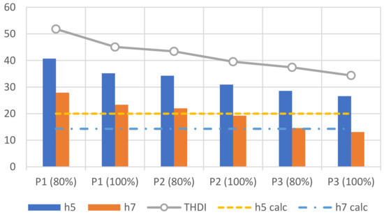
Figure 1.
Harmonic current magnitudes at various equipment loading parameters.
From Figure 1 it follows that only the seventh harmonic current corresponds to the calculated values with a small error at 80% of the equipment loading. The rest of measured values of harmonic magnitudes differ significantly from the calculated values. There is also a tendency to increase total harmonic distortion in current (THDI) with a decrease in the equipment loading.
Thus, there are various approaches to modeling a nonlinear electrical load that are able to accurately describe their operating modes for variable parameters of the supply grid and load. However, to a greater extent this applies to single electrical installations that are connected to a network with a sinusoidal voltage. When modeling an equivalent mixed nonlinear load, some difficulties arise, which especially applies to consumers with a voltage of 0.4 kV:
- -
- a large number of electrical loads with different types, which lead to significant labor costs when modeling each of them;
- -
- discrepancy between the existing power supply scheme and the design scheme of consumers, which leads to significant complexity in the preparation of the electrical equivalent circuit;
- -
- in the design documentation, only generalized load parameters are indicated, which does not allow to accurately identify the parameters of nonlinear electrical load for simulation.
Under such conditions, it is quite difficult to simulate the nonlinear electrical load of the consumer without real measurements at the facility. Direct measurement of the consumer currents makes it possible to determine the currents at harmonic frequencies and use them when modeling a nonlinear load as current sources. However, in the presence of external distortions in the voltage, this approach will be incorrect, since it will not allow separating the external grid distortions from the internal consumer distortions. Therefore, a new approach is needed to evaluate the parameters of a nonlinear electrical load in order to carry out simplified computations of power quality indicators in the presence of external distortions in the supply voltage.
In [41], based on experimental studies of a different types of nonlinear load, it is shown that the parameters of nonlinear load can be determined by connecting a passive harmonic filter to the grid. In this case, the nonlinear load current at harmonic frequency is distributed between the branches of the supply feeder and the passive filter. By measuring these harmonic currents and performing their complex addition, it is possible to determine the parameters of the equivalent nonlinear load of the consumer correctly in the presence of external distortions. This approach can be applied to virtually any enterprise with nonlinear load, provided there is a single-tuned filter. The obtained harmonic current magnitudes of equivalent nonlinear load can be used to increase the accuracy of modeling the nonlinear load and power consumption modes in the presence of harmonics.
This paper further extends the earlier works and aims to assess the impact of the passive filter parameters, the energy system, and load parameters on the determination of nonlinear load harmonic currents. Based on assessment of such factors, it is necessary to develop recommendations for the selection of filter parameters in order to minimize the error in determining harmonic current magnitudes. The remainder of this paper is organized as follows: Section 2 illustrates the proposed method of distortion sources assessment based on application of passive filter and description of the case under study. Section 3 presents the results and discussion. Section 4 concludes this paper.
2. Research Methods
2.1. Method of Distortion Sources Assessment Based on Application of Passive Filter
The method for assessing the parameters of nonlinear electrical load is based on connecting a single-tuned harmonic filter and measuring the currents of the system and the passive filter at harmonic frequencies (Figure 2). In this case, it is assumed that nonlinear load harmonic currents flow through the branches with the energy system impedance and the impedance of the passive harmonic filter. Thus, the summation or subtraction in the complex form of the mentioned currents, depending on their direction, gives the harmonic current of an equivalent nonlinear load of the consumer, which can be further used in modeling and setting the magnitude of nonlinear load in the form of current sources.
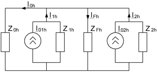
Figure 2.
The scheme for identification nonlinear load current at harmonic frequencies of h order.
From the scheme in Figure 2 it follows that the nonlinear load currents I01h and I02h are divided and flow almost completely through the branches with filter impedance ZFh and system impedance Z0h. Then, we can write the following equation:
where I0h is the energy system harmonic current, IFh is the filter harmonic current. In this case, the system harmonic current and the filter harmonic current can be measured within the consumer. Such measured data make it possible to determine the harmonic magnitude of the equivalent nonlinear load, which in this case consists of two nonlinear consumers.
However, Equation (1) is valid only with a certain error, which can be estimated using the following coefficients:
where Z1h, Z2h is the consumer’s impedance of h order.
According to the superposition method, it is possible to determine the currents I0h and IFh. The energy system harmonic current can be defined as follows:
Filter harmonic current can be defined as follows:
The summation of the currents I0h and IFh gives the following result:
Considering that the coefficients n1h and n2h are much greater than unity at harmonic frequencies, the following expression can be obtained:
Thus, the assumption about the possibility of using a passive filter to determine the parameters of an equivalent nonlinear load is confirmed. An important feature of this method is the determination of the harmonic current magnitudes of nonlinear load, regardless of the external harmonic distortions. This also follows from the superposition method in the presence of external distortions.
When using a passive harmonic filter, the parameters of the filter, system, and load will play an essential role in determining harmonic current of nonlinear load, since with a certain combination of these parameters, resonant phenomena may occur at harmonic frequencies, which may cause an error in determining harmonic current of nonlinear load by the mentioned method.
2.2. Case Study
A simplified equivalent circuit, the parameters of which correspond to an industrial enterprise with small installed capacity, was developed to study the impact of the passive filter, system, and load parameters on the harmonic current estimation of nonlinear load (Figure 3).
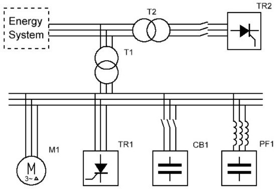
Figure 3.
The scheme under study.
The equivalent circuit parameters are presented in Table 1.

Table 1.
The parameters of the equivalent circuit.
The simulation was carried out in the MATLAB Simulink platform. During the simulation, it was necessary to assess the impact of the passive filter, energy system, and load parameters on the harmonic current computation of nonlinear load. In this case, the values of passive filter resistance varied from 0 to 0.1 Ohm and the values of passive filter capacitance varied within ±30%. The place of nonlinear load connection was also changed, and the capacitor banks were switched on or off. Additionally, the value of the power system impedance was varied from 0 to 0.04 Ohm, which consists of the power system and transformer impedance. The considered simulation options are presented in Table 2.
Table 2.
Simulation parameters.
For example, for the first simulation option, the subject for consideration is a circuit with the initial parameters from Table 1, with the following changes made: TR2 disconnected, the parameters of the filter resistance vary from 0 to 0.01 Ohm for the case of a connected and disconnected capacitor banks.
To determine the harmonic current magnitude of the nonlinear load, a shunt filter, being virtually a short circuit at a tuned harmonic frequency, is connected to the consumer’s buses. In [41], based on experimental studies, it is shown that for a thyristor controlled rectifier, a thyristor power regulator, and a diode uncontrolled rectifier, the relative value of the generated harmonic current to the current at the fundamental frequency remains almost constant before and after connecting the passive filter. It means that the ratio of the current harmonic to the current at the fundamental frequency changes with a small error. Therefore, in this paper, the equivalent nonlinear load is set in the form of a current source at harmonic frequencies during simulation.
In this paper, the task assigned by the authors is to determine the impact of the passive filter, energy system, and load parameters on the accuracy of computation of the harmonic current magnitude of an equivalent nonlinear load for a single consumer. Such parameters are necessary for a more precise setting of nonlinear load parameters when modeling and calculating consumer operating modes in the presence of harmonics. Therefore, the scheme in Figure 3 is considered in view of the first consumer, i.e., only those measured parameters that can be obtained within the first consumer are taken into account. As a result, the dependencies of the nonlinear load harmonic current, the supply system harmonic current of the consumer, the passive filter harmonic current on the parameters of the passive filter, the energy system, and load of the consumer are constructed.
2.3. Experimental Study in Laboratory Test Bench
In the work, experimental measurements were also carried out in the laboratory test bench to confirm the results obtained in the simulation. The single line scheme and test bench view are presented in Figure 4. The laboratory test bench is powered from a three-phase power supply system with a phase voltage of 220 V. In the electrical grid outside the considered consumer, an uncontrolled rectifier UR is connected with a load in the form of heating resistance HR. The consumer load includes a passive harmonic filter PF, a controlled thyristor rectifier TR, an induction motor M with a load in the form of a DC generator, capacitor banks CB. The consumer is connected to the grid through a power line with inductance L.
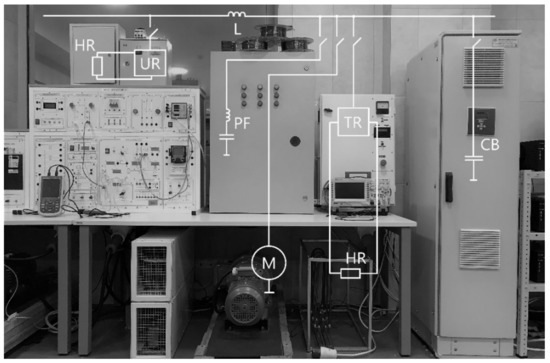
Figure 4.
The single line scheme and test bench view.
The measurements were carried out using an Industrial Scopemeter Fluke 125B. The parameters of the electrical equipment included in the test bench are presented in Table 3.
Table 3.
The equipment parameters of the laboratory bench.
When conducting laboratory studies, the error estimation in determining the fifth harmonic current of the controlled thyristor rectifier was carried out by the current equal to the sum of the passive filter current and the supply system current of the consumer at the harmonic frequency. The measured harmonic current of the nonlinear load before the filter is connected and the nonlinear load current after the filter is connected, which is calculated based on the measured currents of the filter and the supply system, were compared to determine the error. Three modes were considered, in which some parameters were changed: mode 1—equipment parameters correspond to the data from Table 3; mode 2—equipment parameters correspond to the data from Table 3 and there is no power line inductance; mode 3—the equipment parameters correspond to the data from Table 3, there is no line inductance, the capacitance of the passive filter is equal to 60 μF.
3. Results and Discussion
3.1. Simulation without External Distortions
In this block, the scheme in Figure 3 is considered, wherein the non-linear load TR2 is disconnected and the rest of the equipment is connected. The simulation is carried out in accordance with numbers 1–3 from Table 2.
During Simulation 1, the filter resistance was changed. Figure 5 shows the dependencies of the nonlinear load harmonic current ITR1, the supply system harmonic current of the consumer IT1, the harmonic current of the passive filter IPF1, the harmonic current calculated from the summation of the harmonic filter current, and the harmonic system current of the consumer before and after connecting the capacitor banks ISUM1, ISUM2 on the resistance of the filter RF.
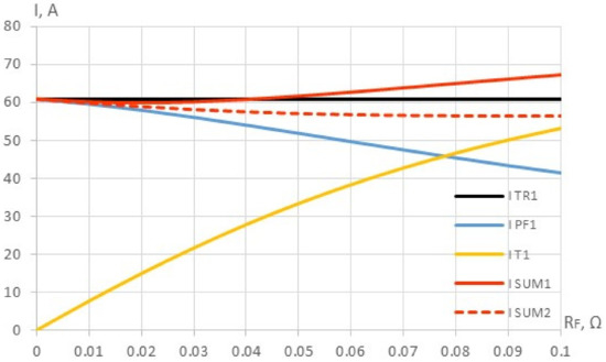
Figure 5.
The dependences of the 5th harmonic currents ITR1, IT1, IPF1, ISUM1, ISUM2 on the passive filter resistance RF.
It is obvious that with an increase in the filter resistance, the harmonic system current of the consumer increases, and the harmonic current of the passive filter decreases. When the filter resistance changes, the harmonic current ISUM1 is substantially equal to the nonlinear load harmonic current ITR1. The error in estimating the harmonic current magnitude of nonlinear load by means of harmonic current ISUM1 increases with an increase in the filter resistance and is about 10% at the maximum value of 0.1 Ohm. This is due to the fact that part of the harmonic current flows through the branch with capacitor banks CB1. Disconnecting CB1 for the time of measurements reduces the estimation error, which at the maximum value of the filter resistance was 7%. It is worth noting that with the rated parameters of the passive filter (Table 2), corresponding to the parameters of the filter at an existing industrial facility, the error in estimating the harmonic current magnitude of nonlinear load current is about 1.6%.
During Simulation 2, the filter capacitance was changed. Figure 6 shows the dependencies of the harmonic currents ITR1, IT1, IPF1, ISUM1, ISUM2 on the capacitance of the filter XCF.
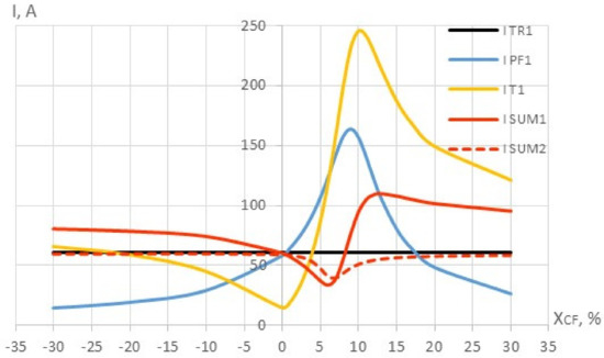
Figure 6.
The dependences of the 5th harmonic currents ITR1, IT1, IPF1, ISUM1, ISUM2 on the passive filter capacitance XCF.
From Figure 6, it follows that with an increase in the filter capacitance, the system harmonic current of the consumer ITR1 and the harmonic current of the passive filter IPF1 increase, which is due to the occurrence of the parallel resonance near the fifth harmonic frequency. In this case, the filter is considered detuned, and its tuning frequency is shifted to higher frequencies. At the fifth harmonic frequency, the passive filter has a capacitive character, which leads to the occurrence of resonant phenomena. It also follows from the graph that the harmonic current ISUM2 with the capacitor banks disconnected is equal to the harmonic current of the nonlinear load ITR1 with any changes in the filter capacitance in the range from −30 to 0%. It appears that in order to accurately estimate the harmonic current of the nonlinear load using a passive filter, its LC circuit should have either active or active-inductive character at the tuned harmonic frequency. It is also necessary to disconnect capacitor banks designed to compensate for reactive power.
During Simulation 3, the transformer impedance was changed. Figure 7 shows the dependencies of the harmonic currents ITR1, IT1, IPF1, ISUM1, ISUM2 on the transformer impedance XT1.
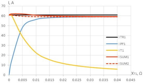
Figure 7.
The dependences of the 5th harmonic currents ITR1, IT1, IPF1, ISUM1, ISUM2 on the energy system impedance XT1.
The calculated harmonic currents ISUM1 and ISUM2 with the CB1 connected and disconnected at the fifth harmonic is substantially equal to the harmonic current of the nonlinear load ITR1. In this case, the change in the transformer impedance virtually does not affect the accuracy of estimating the harmonic current of the nonlinear load according to the proposed method.
3.2. Simulation with External Distortions
In this block, the scheme in Figure 3 is considered, wherein the nonlinear load TR2 and the rest of the equipment are connected. In this case, two consumers are connected to the point of common coupling. One consumer contains mixed load and a passive harmonic filter, and the other consumer contains completely nonlinear load. For visual clarity, the nonlinear load parameters of the first consumer are reduced by ten times (ITR1 = 6.1 A). The simulation is carried out in accordance with numbers 4–6 from Table 2.
During Simulation 4, the filter resistance was changed. Figure 8 shows the dependencies of the nonlinear load harmonic current ITR1, the supply system harmonic current of the consumer IT1, the harmonic current of the passive filter IPF1, the harmonic current calculated from the summation of the harmonic filter current and the harmonic system current of the consumer before and after connecting the capacitor banks ISUM1, ISUM2 on the resistance of the filter RF.
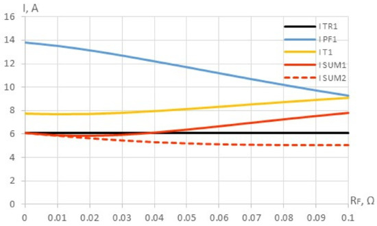
Figure 8.
The dependences of the 5th harmonic currents ITR1, IT1, IPF1, ISUM1, ISUM2 on the passive filter resistance RF (simulation 4).
From the graph it follows that the error in estimating the harmonic current magnitude of nonlinear load by means of harmonic current ISUM1 increases with an increase in the filter resistance and is 28% at its maximum value. When capacitor banks are disconnected, the maximum error is reduced to 16%. At the rated filter parameters (quality factor is 60), the error is about 4%.
During Simulation 5, the filter capacitance was changed. Figure 9 shows the dependencies of the harmonic currents ITR1, IT1, IPF1, ISUM1, ISUM2 on the filter capacitance XCF.
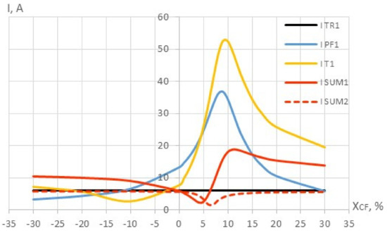
Figure 9.
The dependences of the 5th harmonic currents ITR1, IT1, IPF1, ISUM1, ISUM2 on the passive filter capacitance XCF (simulation 5).
An increase in the filter harmonic current and system harmonic current is due to the occurrence of the parallel resonance near the fifth harmonic. To avoid the occurrence of such a phenomenon, it is necessary to ensure the active-inductive character of the passive filter circuit at the fifth harmonic frequency, i.e., tune it to the frequency of the fifth harmonic and below. With such a tuning, it can be seen from the graph that the harmonic current ISUM2 with the capacitor banks disconnected is equal to the harmonic current of the nonlinear load ITR1, which indicates the efficiency of the method under consideration.
During Simulation 6, the transformer impedance was changed. Figure 10 shows the dependencies of the harmonic currents ITR1, IT1, IPF1, ISUM1, ISUM2 on the transformer impedance XT1.
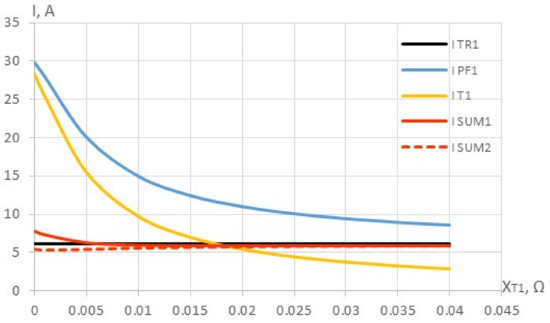
Figure 10.
The dependences of the 5th harmonic currents ITR1, IT1, IPF1, ISUM1, ISUM2 on the transformer impedance XT1 (simulation 6).
From Figure 10, it follows that the harmonic current ISUM2 with the capacitor banks disconnected is substantially equal to the harmonic current of the nonlinear load ITR1. At the rated value of the transformer impedance, the error in estimating harmonic current of nonlinear load is about 5%. The maximum estimation error is equal to 26% with zero transformer impedance and CB1 connected. In this case, the impedance of the first enterprise for the external harmonic current is minimal. As a result, high-ampere harmonic current from the external source flows through the branch with transformer impedance and then gets divided into branches with a passive filter, load, and capacitor banks. The part of the harmonic current that flows through the branch with load and the capacitor banks is not considered when calculating the harmonic current of nonlinear load and increases the computation error. However, in real conditions, in the presence of transformer impedance, the external harmonic currents virtually do not affect the determination of the harmonic current magnitude of nonlinear load at the enterprise under consideration.
3.3. Current Waveforms during Simulation
For a more detailed understanding of the proposed method, current waveforms were obtained (Figure 11), which are necessary to calculate the harmonic current of nonlinear load (h = 5).
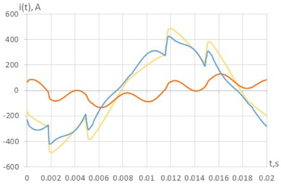
Figure 11.
Current waveforms during simulation: passive filter current iPF (red line), supply system current iT (blue line), calculated current iSUM (yellow line).
The model parameters were close to the test bench parameters in terms of the load ratio and composition: external nonlinear load TR2 and capacitor banks CB1 were connected, the transformer impedance was doubled, the power ratio of the linear load M1 and the nonlinear load TR1 was equal to the ratio of these parameters in laboratory studies, the nonlinear load parameters (TR1, TR2) were set according to Table 1. Calculated current iSUM was defined as the sum of the currents iPF and iT. The fifth harmonic current of the nonlinear load was calculated based on the Fourier transform. As a result, the fifth harmonic current was equal to 62.4 A, and the error relative to the true value was 2.3%.
3.4. Experimental Study in Laboratory Test Bench
This block presents the results of experimental studies on a laboratory bench, described in Section 2.3. The instantaneous current of the nonlinear load was calculated by measuring the instantaneous current of the consumer supply feeder (blue line), the instantaneous current of the passive filter (red line), and their subsequent subtraction (yellow line). The subtraction had to be applied due to the selected current clamp connection during the measurement (source to load). Figure 12 shows current waveforms for one of the studied modes (additional inductance, external nonlinear load, capacitor banks were connected).
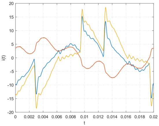
Figure 12.
Current waveforms during experimental study: passive filter current iPF (red line), supply system current iT (blue line), calculated current iSUM (yellow line).
The error in determining the fifth harmonic current of a nonlinear load was calculated relative to the fifth harmonic current of thyristor rectifier, which was measured when it was only connected to the power supply system. Cases were considered in which the parameters of the power supply line and passive harmonic filter were changed, as well as the capacitor banks and the uncontrolled rectifier were connected or disconnected. The error estimation data are presented in Table 4.
Table 4.
The relative error estimation for various modes of test bench load.
It follows from the data in Table 4 that the error in estimating the fifth harmonic current of nonlinear load based on measurements of the supply feeder current and passive filter current does not exceed 5% for the considered modes. In this case, the maximum error is observed when an additional inductance is connected (mode 1), the minimum error corresponds to the case without inductance in the power line (mode 2), and the error increases within small limits when the filter capacitance changes (mode 3). It should also be noted that an external source of distortion does not significantly affect the error for the cases under consideration.
Laboratory studies were carried out when a passive harmonic filter was connected, the parameters of which were selected taking into account the results obtained during the simulation. The quality factor of the passive filter was approximately equal to 60, the filter circuit had an active-inductive character at the fifth harmonic frequency. It should also be noted that when a passive filter was connected in laboratory conditions, the supply feeder current decreased at the fundamental frequency. This leads to an increase in the calculated nonlinear load current at the fundamental frequency and may affect the current computation at the fifth harmonic frequency. However, the influence of such a factor for the selected type of nonlinear load in laboratory conditions was insignificant. To reduce this influence, it is necessary to select the filter parameters based on the minimum compensating ability at the fundamental frequency.
4. Conclusions
Thus, in this work, a method was proposed and tested for determining the harmonic currents of equivalent nonlinear load in the presence of external distortions. The impact of the passive filter parameters, the energy system, and load parameters on the computation of nonlinear load harmonic currents with application of single tuned harmonic filter have been revealed. The factors that most affect the error in calculating the harmonic current of nonlinear load based on the measurements of filter harmonic current and supply system harmonic current have been identified. The main advantage of the proposed method is the separation of external and internal distortions, which makes it possible to correctly estimate the parameters of the nonlinear load of a single consumer. It should also be noted that the proposed method has disadvantages: a filter is required for each tuned harmonic; an additional device is required if the consumer does not have a passive filter; the passive filter is connected temporarily as a measuring device, after its disconnection, the parameters of the nonlinear load may change. The obtained simulation results were confirmed experimentally on a laboratory test bench. Based on the conducted research, the following recommendations for the selection of passive harmonic filter parameters have been developed in order to minimize the error in determining harmonic current of nonlinear load in the presence of external distortions:
- The lower the passive filter resistance, the higher the accuracy of estimating the harmonic current of nonlinear load. In this case, the error does not exceed 5% for filter quality factor values from 20 to 120. In addition, it is necessary to take into account the current overload ratio of the filter, since a decrease in its resistance results in an increase in the current through the filter at harmonic frequencies.
- It is necessary to disconnect the capacitor banks for the reactive power compensation during the measurements of supply system harmonic current and filter harmonic current, since part of the harmonic current that flows through the capacitor banks at harmonic frequencies is not accounted for when performing computations of nonlinear load harmonic current.
- A passive filter should have active or active-inductive character at a tuned frequency in order to avoid the resonance phenomena with the grid impedance. Therefore, filter tuning should be made to the frequency of the generated harmonic by nonlinear load, or to a lower frequency.
- The generated reactive power of the passive filter at the fundamental frequency should not affect the voltage at the consumer’s buses. In this case, voltage deviations can affect the accuracy of calculating the harmonic current magnitudes of a nonlinear load.
Further research opportunities include the development of a mobile measuring device based on the passive filter application and its testing and implementation at industrial plants with a voltage of 0.4 kV.
Author Contributions
Conceptualization, A.S.; Methodology, A.S. and A.B.; Investigation, I.G. and V.D.; Writing—original draft preparation, A.S.; Supervision and project administration, A.S. and A.B.; Writing—review and editing, A.S. and V.D. All authors have read and agreed to the published version of the manuscript.
Funding
This research was financially supported by the Russian Science Foundation grant No. 21-79-10027, https://rscf.ru/en/project/21-79-10027/ (accessed date 20 February 2022).
Institutional Review Board Statement
Not applicable.
Informed Consent Statement
Not applicable.
Conflicts of Interest
The authors declare no conflict of interest.
Nomenclature
| THDI | Total harmonic distortion in current |
| THDU | Total harmonic distortion in voltage |
| h | Harmonic order |
| h5 (h7) calc | Calculated 5th (7th) harmonic magnitude |
| h5 (h7) | Measured 5th (7th) harmonic magnitude |
| I01h, I02h | Nonlinear load currents of the consumers (vector value) |
| I0h | Energy system harmonic current of h order (vector value) |
| IFh | Filter harmonic current of h order (vector value) |
| Z0h | Energy system impedance of h order (vector value) |
| ZFh | Filter impedance of h order (vector value) |
| Z1h, Z2h | Consumer impedance of h order (vector value) |
| T1, T2 | Supply transformer |
| ES | Energy system |
| M1 | Induction motor of the first consumer |
| TR1, TR2 | Thyristor rectifier |
| CB1 | Capacitor banks of the first consumer |
| PF1 | Passive filter of the first consumer |
| UR | Uncontrolled rectifier |
| HR | Heating resistance |
| RF | Filter resistance |
| XCF | Filter capacitance |
| ITR1 | Nonlinear load harmonic current magnitude of consumer |
| IT1 | Supply system harmonic current magnitude of the consumer |
| IPF1 | Passive filter harmonic current magnitude of the consumer |
| ISUM1 | Harmonic current magnitude calculated from the summation of the harmonic filter current and the harmonic system current of the consumer before connecting the capacitor banks |
| ISUM2 | Harmonic current magnitude calculated from the summation of the harmonic filter current and the harmonic system current of the consumer after connecting the capacitor banks |
References
- Bogdanov, I.; Abramovich, B. Improving the Efficiency of Autonomous Electrical Complexes of Oil and Gas Enterprises. J. Min. Inst. 2021, 249, 408–416. [Google Scholar] [CrossRef]
- Almeida, C.F.M.; Kagan, N. Harmonic Coupled Norton Equivalent Model for Modeling Harmonic-Producing Loads. In Proceedings of the 14th International Conference on Harmonics and Quality of Power-ICHQP, Bergamo, Italy, 26–29 September 2010; IEEE: Manhattan, NY, USA, 2010; pp. 1–9. [Google Scholar] [CrossRef]
- Shabalov, M.Y.; Zhukovskiy, Y.L.; Buldysko, A.D.; Gil, B.; Starshaia, V.V. The Influence of Technological Changes in Energy Efficiency on the Infrastructure Deterioration in the Energy Sector. Energy Rep. 2021, 7, 2664–2680. [Google Scholar] [CrossRef]
- Shklyarskiy, Y.; Guerra, D.D.; Iakovleva, E.; Rassõlkin, A. The Influence of Solar Energy on the Development of the Mining Industry in the Republic of Cuba. J. Min. Inst. 2021, 249, 427–440. [Google Scholar] [CrossRef]
- Korolev, N.; Kozyaruk, A.; Morenov, V. Efficiency Increase of Energy Systems in Oil and Gas Industry by Evaluation of Electric Drive Lifecycle. Energies 2021, 14, 6074. [Google Scholar] [CrossRef]
- Beltran-Carbajal, F.; Tapia-Olvera, R.; Valderrabano-Gonzalez, A.; Yanez-Badillo, H. An Asymptotic and Algebraic Estimation Method of Harmonics. Electr. Power Syst. Res. 2022, 206, 107771. [Google Scholar] [CrossRef]
- Jiménez Carrizosa, M.; Stankovic, N.; Vannier, J.-C.; Shklyarskiy, Y.; Bardanov, A. Multi-Terminal DC Grid Overall Control with Modular Multilevel Converters. J. Min. Inst. 2020, 243, 357. [Google Scholar] [CrossRef]
- Senchilo, N.D.; Ustinov, D.A. Method for Determining the Optimal Capacity of Energy Storage Systems with a Long-Term Forecast of Power Consumption. Energies 2021, 14, 7098. [Google Scholar] [CrossRef]
- Zhukovskiy, Y.; Tsvetkov, P.; Buldysko, A.; Malkova, Y.; Stoianova, A.; Koshenkova, A. Scenario Modeling of Sustainable Development of Energy Supply in the Arctic. Resources 2021, 10, 124. [Google Scholar] [CrossRef]
- Mayordomo, J.G.; Beites, L.F.; Yang, X.; Xu, W. A Detailed Procedure for Harmonic Analysis of Three-Phase Diode Rectifiers Under Discontinuous Conduction Mode and Nonideal Conditions. IEEE Trans. Power Deliv. 2018, 33, 741–751. [Google Scholar] [CrossRef]
- Kryltcov, S.B.; Solovev, S.V.; Munoz-Guijosa, J.M. Application of an active rectifier used to mitigate currents distortion in 6–10 kV distribution grids. J. Min. Inst. 2019, 236, 229–238. [Google Scholar] [CrossRef]
- Mayordomo, J.G.; Carbonero, Á.; Beites, L.F.; Asensi, R.; Xu, W. A Contribution Towards a General and Systematic Procedure for Modeling Line Commutated AC/DC Converters in the Harmonic Domain. IEEE Trans. Power Deliv. 2009, 24, 2415–2427. [Google Scholar] [CrossRef]
- Alexandrov, V.I.; Kopteva, A.V.; Serzan, S.L. Effective Parameters of Tail Processing of Gold-Bearing Ore Hydrotransport for Verninskaya Processing Factory. Key Eng. Mater. 2020, 836, 25–35. [Google Scholar] [CrossRef]
- Lian, K.L.; Perkins, B.K.; Lehn, P.W. Harmonic Analysis of a Three-Phase Diode Bridge Rectifier Based on Sampled-Data Model. IEEE Trans. Power Deliv. 2008, 23, 1088–1096. [Google Scholar] [CrossRef]
- Sun, Y.; Zhang, G.; Xu, W.; Mayordomo, J.G. A Harmonically Coupled Admittance Matrix Model for AC/DC Converters. IEEE Trans. Power Syst. 2007, 22, 1574–1582. [Google Scholar] [CrossRef]
- Voronin, V.; Nepsha, F. Simulation of the Electric Drive of the Shearer to Assess the Energy Efficiency Indicators of the Power Supply System. J. Min. Inst. 2021, 246, 633–639. [Google Scholar] [CrossRef]
- Shklyarskiy, Y.E.; Shklyarskiy, A.Y.; Zamyatin, E.O. Analysis of Distortion-Related Electric Power Losses in Aluminum Industry. Tsvetnye Met. 2019, 4, 84–91. [Google Scholar] [CrossRef]
- Grotzbach, M.; Redmann, R. Line Current Harmonics of VSI-Fed Adjustable-Speed Drives. IEEE Trans. Ind. Appl. 2000, 36, 683–690. [Google Scholar] [CrossRef]
- Borisov, S.; Koltunova, E.; Kladiev, S. Traction Asynchronous Electric Drive of Mine Electric Locomotive Simulation Model Structure Improvement. J. Min. Inst. 2021, 247, 1–8. [Google Scholar] [CrossRef]
- Carpinelli, G.; Iacovone, F.; Russo, A.; Varilone, P.; Verde, P. Analytical Modeling for Harmonic Analysis of Line Current of VSI-Fed Drives. IEEE Trans. Power Deliv. 2004, 19, 1212–1224. [Google Scholar] [CrossRef]
- Thakur, S.; Odavic, M.; Allu, A.; Zhu, Z.Q.; Atallah, K. Analytical Modelling and Optimization of Output Voltage Harmonic Spectra of Full-Bridge Modular Multilevel Converters in Boost Mode. IEEE Trans. Power Electron. 2022, 37, 3403–3420. [Google Scholar] [CrossRef]
- Wciślik, M. Analytical Model of Single-Phase AC Circuit with Inductance and Bridge Rectifier. Przegląd Elektrotechniczny 2018, 1, 128–131. [Google Scholar] [CrossRef]
- Zeng, Z.; Xiao, H.; Niu, C.; Chen, J.; Wang, Z.; Wu, X.; Cheng, M. An Improved Impedance Modeling Method of Grid-Tied Inverters with White-Box Property. IEEE Trans. Power Electron. 2022, 37, 3980–3989. [Google Scholar] [CrossRef]
- Hansen, S.; Asiminoaei, L.; Blaabjerg, F. Simple and Advanced Methods for Calculating Six-Pulse Diode Rectifier Line-Side Harmonics. In Proceedings of the 38th IAS Annual Meeting on Conference Record of the Industry Applications Conference, Salt Lake City, UT, USA, 12–16 October 2003; IEEE: Manhattan, NY, USA, 2003; Volume 3, pp. 2056–2062. [Google Scholar] [CrossRef]
- Iakovleva, E.; Belova, M.; Soares, A. Allocation of Potentially Environmentally Hazardous Sections on Pipelines. Geosciences 2020, 11, 3. [Google Scholar] [CrossRef]
- Faifer, M.; Laurano, C.; Ottoboni, R.; Toscani, S.; Zanoni, M. Frequency-Domain Nonlinear Modeling Approaches for Power Systems Components—A Comparison. Energies 2020, 13, 2609. [Google Scholar] [CrossRef]
- Gao, B.; Wang, Y.; Xu, W. Modeling Voltage Source Converters for Harmonic Power Flow Studies. IEEE Trans. Power Deliv. 2021, 36, 3426–3437. [Google Scholar] [CrossRef]
- Guarderas, G.; Frances, A.; Ramirez, D.; Asensi, R.; Uceda, J. Blackbox Large-Signal Modeling of Grid-Connected DC-AC Electronic Power Converters. Energies 2019, 12, 989. [Google Scholar] [CrossRef]
- John, M.; Mertens, A. Frequency-Domain Modeling of Harmonic Interactions in Voltage-Source Inverters with Closed-Loop Control. Energies 2020, 13, 5823. [Google Scholar] [CrossRef]
- Li, F.; Wang, Y.; Wu, F.; Huang, Y.; Liu, Y.; Zhang, X.; Ma, M. Review of Real-Time Simulation of Power Electronics. J. Mod. Power Syst. Clean Energy 2020, 8, 796–808. [Google Scholar] [CrossRef]
- Kovernikova, L.I.; Luong, V.C. New Approach to Modeling the Nonlinear Loads. E3S Web Conf. 2019, 139, 01055. [Google Scholar] [CrossRef]
- Nassif, A.B.; Yong, J.; Xu, W. Measurement-Based Approach for Constructing Harmonic Models of Electronic Home Appliances. IET Gener. Transm. Distrib. 2010, 4, 363. [Google Scholar] [CrossRef]
- Abdullah, A.R.; Abidullah, N.A.; Shamsudin, N.H.; Ahmad, N.H.H.; Jopri, M.H. Power Quality Signals Classification System Using Time-Frequency Distribution. Appl. Mech. Mater. 2014, 494–495, 1889–1894. [Google Scholar] [CrossRef]
- Jopri, M.H.; Abdullah, A.R.; Manap, M.; Sutikno, T.; Ab Ghani, M.R. An Identification of Multiple Harmonic Sources in a Distribution System by Using Spectrogram. Bull. Electr. Eng. Inform. 2018, 7, 244–256. [Google Scholar] [CrossRef]
- Jopri, M.H.; Abdullah, A.R.; Manap, M.; Yusoff, M.R.; Sutikno, T. A Fast Localization of Multiple Harmonic Sources for Rectifier Loads by Utilizing Periodogram. TELKOMNIKA Telecommun. Comput. Electron. Control. 2017, 15, 71. [Google Scholar] [CrossRef][Green Version]
- Manap, M.; Jopri, M.H.; Abdullah, A.R.; Karim, R.; Yusoff, M.R.; Azahar, A. A Verification of Periodogram Technique for Harmonic Source Diagnostic Analytic by Using Logistic Regression. TELKOMNIKA Telecommun. Comput. Electron. Control. 2019, 17, 497. [Google Scholar] [CrossRef][Green Version]
- Jopri, M.H.; Abdullah, A.R.; Sutikno, T.; Manap, M.; Ghani, M.R.A.; Yusoff, M.R. A Critical Review of Time-Frequency Distribution Analysis for Detection and Classification of Harmonic Signal in Power Distribution System. Int. J. Electr. Comput. Eng. 2018, 8, 4603. [Google Scholar] [CrossRef][Green Version]
- Jopri, M.H.; Ab Ghani, M.R.; Abdullah, A.R.; Manap, M.; Sutikno, T.; Too, J. K-Nearest Neighbor and Naïve Bayes Based Diagnostic Analytic of Harmonic Source Identification. Bull. Electr. Eng. Inform. 2021, 9, 2650–2657. [Google Scholar] [CrossRef]
- Jopri, M.H.; Abdullah, A.R.; Manap, M.; Yusoff, M.R.; Sutikno, T.; Habban, M.F. An Improved of Multiple Harmonic Sources Identification in Distribution System with Inverter Loads by Using Spectrogram. Int. J. Power Electron. Drive Syst. 2016, 7, 1355. [Google Scholar] [CrossRef]
- Shawon, M.H.; Barczentewicz, S.; Bień, A.; Hanzelka, Z. Localization of Harmonic Sources in Power System-Simulation and Laboratory Study. Renew. Energy Power Qual. J. 2016, 14, 546–551. [Google Scholar] [CrossRef]
- Skamyin, A.; Shklyarskiy, Y.; Dobush, V.; Dobush, I. Experimental Determination of Parameters of Nonlinear Electrical Load. Energies 2021, 14, 7762. [Google Scholar] [CrossRef]
- Busatto, T.; Ravindran, V.; Larsson, A.; Rönnberg, S.K.; Bollen, M.H.J.; Meyer, J. Deviations between the Commonly-Used Model and Measurements of Harmonic Distortion in Low-Voltage Installations. Electr. Power Syst. Res. 2020, 180, 106166. [Google Scholar] [CrossRef]
- Kryltcov, S.; Makhovikov, A.; Korobitcyna, M. Novel Approach to Collect and Process Power Quality Data in Medium-Voltage Distribution Grids. Symmetry 2021, 13, 460. [Google Scholar] [CrossRef]


Publisher’s Note: MDPI stays neutral with regard to jurisdictional claims in published maps and institutional affiliations. |
© 2022 by the authors. Licensee MDPI, Basel, Switzerland. This article is an open access article distributed under the terms and conditions of the Creative Commons Attribution (CC BY) license (https://creativecommons.org/licenses/by/4.0/).