Abstract
In the contemporary era, dizziness is a prevalent ailment among patients. It can be caused by either vestibular neuritis or a stroke. Given the lack of diagnostic utility of instrumental methods in acute isolated vertigo, the differentiation of vestibular neuritis and stroke is primarily clinical. As a part of the initial differential diagnosis, the physician focuses on the characteristics of nystagmus and the results of the video head impulse test (vHIT). Instruments for accurate vHIT are costly and are often utilized exclusively in healthcare settings. The objective of this paper is to review contemporary methodologies for accurately detecting the position of pupil centers in both eyes of a patient and for precisely extracting their coordinates. Additionally, the paper describes methods for accurately determining the head rotation angle under diverse imaging and lighting conditions. Furthermore, the suitability of these methods for vHIT is being evaluated. We assume the maximum allowable error is 0.005 radians per frame to detect pupils’ coordinates or 0.3 degrees per frame while detecting the head position. We found that for such conditions, the most suitable approaches for head posture detection are deep learning (including LSTM networks), search by template matching, linear regression of EMG sensor data, and optical fiber sensor usage. The most relevant approaches for pupil localization for our medical tasks are deep learning, geometric transformations, decision trees, and RASNAC. This study might assist in the identification of a number of approaches that can be employed in the future to construct a high-accuracy system for vHIT based on a smartphone or a home computer, with subsequent signal processing and initial diagnosis.
1. Introduction
Sudden-onset dizziness is one of the most common reasons patients seek medical attention at an emergency department. While benign conditions like vestibular neuritis can cause acute dizziness, more life-threatening disorders like vertebrobasilar stroke are also possible. Because instrumental diagnostic techniques like CT (computed tomography) or MRI (magnetic resonance imaging) of the brain are not always useful for acute isolated vertigo, the differentiation between vestibular neuritis and stroke often depends on clinical criteria alone. As part of the initial differential diagnosis, the physician is guided by the characteristics of nystagmus and the results of the video head impulse test (vHIT). Unambiguous signs of reduced vestibulo-ocular reflex function on the side opposite to the direction of the fast phase of spontaneous nystagmus confirm the diagnosis of vestibular neuritis [1,2,3].
The technique of classical vHIT involves fixing the patient’s gaze on the nose of the researcher during a sharp, unpredictable, passive rotation of the head in the horizontal plane. This is performed at a low amplitude (no more than 10–15° to the right or left of the median position) (Figure 1) [4].
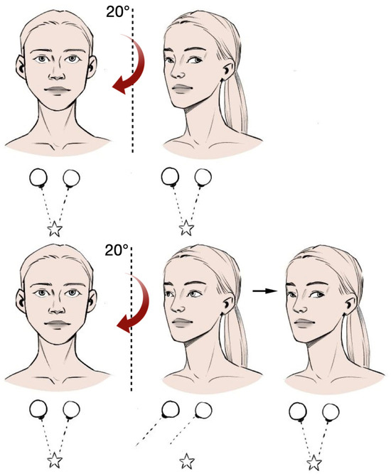
Figure 1.
Evaluation of nystagmus and video head impulse test.
A positive (pathologic) test result is indicated by the appearance of a corrective saccade following head rotation to the affected side, followed by gaze return to the target (the nose of the researcher). This phenomenon is most often observed in cases of peripheral lesions. In vestibular neuronitis, the test is positive on the affected side in 82% of cases [5]. The incorporation of videonystagmography and vHIT into the clinical diagnostic protocol has been demonstrated to enhance the specificity of differential diagnosis between vestibular neuronitis and stroke from 63% to 81% [6]. This evidence reinforces the rationale for the introduction of bedside vHIT assessment into clinical practice within emergency neurology, which can be achieved by developing a special smartphone application.
The vHIT is currently one of the few investigative techniques that can identify the disorder of each semicircular canal of the inner ear. The study does not cause nausea or dizziness and is well tolerated.
Currently, the vHIT examination is conducted in medical institutions in the majority of cases in the following manner. The patient wears special glasses with a camera installed in them. The camera records eye movements during sharp, impulsive movements of the head. The recognized eye and head movements are displayed on the corresponding graphs of coordinates from time, which are analyzed by the doctor. However, the instrument, in the form of glasses with a camera and the software, is quite expensive, which may limit its use as a common tool for vHIT.
Curthoys et al. [7] demonstrated that numerous variables can influence the outcomes of the vHIT. However, when a physician possesses both experience and expertise in administering the test, the substantial value of this rapid and straightforward assessment becomes evident. As this article suggests, meticulous attention to detail (described below) is of paramount importance. In order to enhance the quality and reproducibility of vHIT tests, the article recommends paying close attention to the following aspects:
- The position of the glasses on the patient;
- The instructions given to the patient;
- The reproducibility of the results;
- The speed of the patient’s head during the test;
- The quality of the verification of the results;
- The age of the patient;
- The illumination of the patient’s face.
Medical signal processing methods are continuously improving [8,9,10,11]. The objective of this paper is to examine the existing methods for detecting head and eye positions, as these two aspects represent the fundamental elements of the vHIT test. In addition to a concise literature review, this paper will contrast the techniques for identifying the head position and pupils of a patient. While the article does not present specific algorithms for head pose estimation, it is nevertheless a valuable contribution to the methodology of the vHIT test.
2. Methods of Estimating the Position of the Human Head
The range of methods used to estimate the position of the human head is quite extensive, particularly due to the diverse types of sensors employed as signal sources and the varying applications of specific methods. Additionally, the developer’s requirement for accuracy and speed of execution of this algorithm plays a pivotal role in the selection of a particular algorithm. In this section of the paper, we will demonstrate the multitude of head pose estimation algorithms. In Section 2.1, we provide methods to process impedance sensor data. In Section 2.2, Section 2.3, Section 2.4, Section 2.5, Section 2.6 and Section 2.7, we provide methods to process camera data. In Section 2.8, there are methods to process IMU sensor data. In Section 2.9, there are methods to process EMG (electromyography) sensor data. Finally, in Section 2.10, we provide methods to process optical fiber sensor data.
2.1. Classical Machine Learning
In this section, the signal source is impedance sensor. Classical machine learning methods, due to their computational simplicity, are evidently used in computer vision topics. In their work, Yiwen Jiang et al. [12] presented a head position monitoring and classification system using thin, flexible, strain-sensitive threads placed on the human neck. A concise overview of the algorithm for head pose estimation using such sensors is as follows:
- The data from the sensors is subjected to pre-filtering, normalization, and segmentation in time.
- A set of features is extracted from the segments, which serve as the basis for head orientation classification. The data are partitioned manually.
- Nine classifiers are trained and tested using the available data.
The results are shown in Table 1.

Table 1.
Average test accuracy for different classifiers. In the context of machine learning, the terms “KNN” and “SVM” refer to two distinct classifier algorithms, the k-nearest neighbor and the support vector machine, respectively.
A combination of regression and classification methods can also be effective for head pose estimation. For instance, in the work [13], the so-called WSM (Web-shaped model) approach entails estimating the head pose through the application of two cascaded approaches:
- We feed a face photo as input, and a landmark detector extracts the coordinates of 68 landmarks of the face;
- The WSM draws a virtual web on the face, and a descriptive array of facial poses is extracted based on the position of landmarks.
The regression and classification models are subsequently integrated to ascertain the Euler angles. The minimum mean absolute error (MAE) for the three regression models ranged from 3.05 to 5.99 degrees.
2.2. Deep Learning Methods
A comprehensive category of algorithms for detecting head positions is deep neural networks. In their paper [14], Yuanming Cao et al. propose a head pose estimation algorithm based on deep learning. The authors assert that the developed algorithm is robust to background illumination and other noise. The configuration of the convolutional neural network is illustrated in Figure 2.
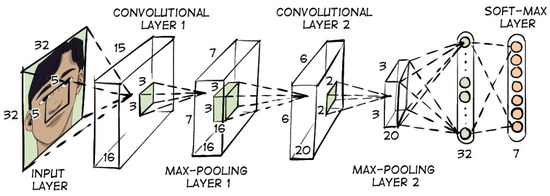
Figure 2.
Convolutional neural network configuration for head position estimation.
The accuracy of head position classification was found to be up to 0.93 with a data size of 12,502 individuals. Yijun Zhou et al. [15] developed an algorithm that is capable of detecting the angles of a person’s head from three planes. The algorithm is capable of detecting angles at all positions of the face relative to the camera. The algorithm is based on a convolutional neural network with separate fully connected layers that classify pitch, roll, and yaw angles (Euler angles) into ranges of 3 degrees each. In [16], Nataniel Ruiz et al. propose a method for estimating head position by using convolutional neural networks. A distinctive feature of this approach is the incorporation of multiple loss functions for the purpose of predicting Euler angles. The MAE prediction error was 5.324 degrees. In [17], Jingrui Yu et al. also use convolutional neural networks to estimate head position (Figure 3), but the training uses data from an omnidirectional camera that is in motion while recording data.
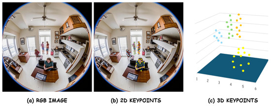
Figure 3.
Example of an image obtained from an omnidirectional camera after image processing. Blue, green, orange, yellow points depict different people.
In their study, Khalil Khan et al. [18] examine the efficacy of a face image segmentation approach in head pose estimation (Figure 4).
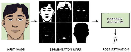
Figure 4.
Example of face image segmentation.
The algorithm comprises two modules: multiclass facial segmentation and head pose estimation. The authors highlight the informativeness of this segmentation in head pose estimation. In their paper [19], Xiang Xu et al. investigate global and localized features obtained by convolutional neural networks. These features are used to learn to estimate both head position and landmark localization. The authors demonstrate that the developed algorithm, named JFA (joint head pose estimation and face alignment algorithm), improves head pose estimation compared to SVR, Random Forest model, and G-Net neural network. In [20], authors Heng Song et al. demonstrate that their multi-task deep learning method, which combines face recognition and pose estimation, is more efficient than classical two-stage methods (face recognition followed by estimating head rotation). The accuracy of the orientation angle estimation of their one-stage algorithm is 1.96 degrees (MAE). In [21], a 3D head pose estimation system was developed based on a deep learning face analysis model. A face-part segmentation system was developed using deep convolutional neural networks (DCNNs). The MAE of head angle detection for different datasets varies from 4.3 to 2.02 degrees. The paper [22] presents a comprehensive system for head and shoulder pose estimation based on depth images alone (Figure 5). The core component of the developed framework is a convolutional neural network, which accepts three types of images as input and generates a 3D object position as output.
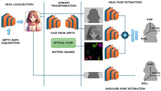
Figure 5.
Overview of the proposed system. Depth sensors (black) acquire the depth images to simply localize head position using CNN (convolutional neural network). The head crop is used to produce the three inputs for the following networks (green), which are then merged to output the head pose (red). The Face-from-Depth architecture reconstructs gray-level face images from the corresponding depth maps, while the Motion Images are obtained by applying the Farnerback algorithm. Finally, the upper-body crop is used for the shoulder pose estimation (orange).
Experimental results demonstrate that this method outperforms several recent developments based on both intensity and depth of input data, operating in real-time at over 30 frames per second. Patrizia Paggio et al. [23] present an automated method for detecting and classifying head movements based on video recordings of face-to-face conversations in Danish involving 12 native speakers. A number of classifiers were trained on different combinations of visual, acoustic, and verbal features and tested by full cross-validation. The classifier that yielded the most optimal results was a multilayer perceptron, which scored an average of 0.68 F1 points for head motion detection and 0.40 for classifying head motion into four different classes.
2.3. Attention Networks
It is worth noting that a novel class of tools, attention networks, has recently emerged. In their work [24], Jin Han et al. propose an approach based on dividing the original image into five streams and then extracting features in each stream. These streams are distinguished by activation features and pooling layers. The outputs of each block of the different streams are combined with each other to produce five feature vectors, which are then combined into a single feature vector. The resulting vector is then fed into the input of the SSR-Net model (Soft Stagewise Regression Network). The MAE of determining Euler angles from several datasets varies from 5.02 to 15.77 degrees.
2.4. Geometric Transformations
Geometric transformation-based methods occupy a significant position in this field. For instance, in their work [25], the authors Marco La Cascia et al. utilize a stream of incoming images to approximate the head shape. The head model is represented as a cylinder. The incoming images are projected onto the cylinder model, and then a texture map is calculated for each frame. The position of the cylinder is calculated using geometry formulas. The authors report that this approach provides robustness to changes in frame illumination. In [26], Sun Wenzhu et al. propose a head pose estimation method for flight training simulation. The authors describe the principle of a computer vision algorithm called POSIT (Pose from Orthography and Scaling with Iterations). In [27], a method (Figure 6) based on geometric calculations is described to accurately estimate head pose from only one 2D face image at very low computational cost. Testing the method on publicly available data revealed that the proposed method can estimate head poses with greater accuracy and a shorter execution time than state-of-the-art methods based on geometric transformations. It has been reported that even when compared to state-of-the-art methods with additional depth information, the proposed method still provides comparable performance.
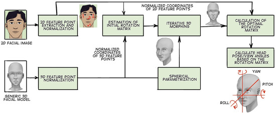
Figure 6.
An illustration of the method based on geometric calculations.
2.5. Decision Trees
Decision trees (e.g., Random Forest) are also popular in big data, in particular with images. Their main advantages are their ability to estimate the importance of each image feature and their high learning rate. In [28], Gabriele Fanelli et al. propose an approach for head pose estimation using additional image depth data. The basis is a random trees ensemble model. The random trees are trained by splitting each image, which simultaneously reduces the entropy of the class label distribution and the variance of head position and orientation. In [29], Hyunduk Kim et al. presented an approach for head pose estimation in gray-level images. A random forest method was used to deal with a large training dataset. To make this system robust to illumination, a run-length matrix was used. Experimental results show that the algorithm is efficient and robust to illumination changes.
2.6. Search by Template Matching
One of the common methods of object recognition in computer vision is template matching (image template matching search). This approach allows us to determine whether a particular object is present in an image and, if so, in which part of the image it is located. In [30], Xinghua Li et al. describe an algorithm for estimating head rotation, which can achieve an accuracy of approximately 92%. The algorithm, based on template matching, can detect the corresponding relation between the peak level of the color histogram of individual image regions and the color of a particular head region. The head region in the image is subdivided into four smaller regions, each of which has its own color and location information. The information from these four regions is used to estimate the head rotation state. In [31], a computer vision approach is proposed that recognizes the head movements of a user sitting at a desk. The authors achieve detection through correlation-based template matching, whereby the sets of templates are matched to each head image captured by a camera located at the top of the monitor. The accuracy of head motion tracking is 1.4°, and the processing speed is 8 images per second. Paper [32] presents an efficient approach for head detection in single-depth images at low computational cost. A descriptor is developed and used to classify pixels as head (pixel belongs to head region) or non-head (pixel does not belong to head region). The experiments yielded high head detection performance, with 90% accuracy for a dataset recorded by the authors containing images with different body positions, head poses, and distances to the Kinect sensor. Over 70% accuracy was achieved for a publicly available dataset consisting of several daily activities, which is higher than that of the head and shoulder pose detection method using HOG (histogram of oriented gradients).
2.7. Viola–Jones Algorithm
A popular algorithm that is primarily used to recognize a person’s face in an image is the Viola–Jones algorithm. The paper [33] by Anwar Saeed et al. proposes to estimate head position using a face detector that is similar to the Viola–Jones method. Additionally, the depth of objects in the image obtained using the Kinect device is used as additional data. A variety of features are extracted, including those based on Gabor filter (GAB), local binary patterns (LBP), histogram of oriented gradients (HOG), head point cloud (HPC) objects, multi-scale comparative depth plots (MCDP), and depth geometry feature functions. The support vector regression method is used as a machine learning model. The developed algorithm is capable of detecting faces in poses covering pitch ±30°, roll ±20°, and yaw ±40°. The authors cite different accuracies of the algorithm for different combinations of features. However, the execution time of the described algorithm is expected to be considerably longer than that of the algorithm described in [30]. In their paper, Euclides N. Arcoverde Neto et al. [34] proposed a method for detecting the position of the human head using a mobile device. The algorithm is composed of several blocks:
- Face recognition using an optimized Viola–Jones algorithm;
- Nose position recognition;
- Eye position recognition;
- The overall head position (roll, yaw, and pitch angle) is calculated from the nose and eye positions.
The results of applying this algorithm to 363 videos recorded from 27 patients demonstrate that the accuracy of real-time head position detection using a smartphone camera is 70%. This result is primarily attributed to the presence of sudden movements that the frame rate is unable to sufficiently detail.
2.8. IMU Sensor Usage for Head Position Estimation
Let us also consider head pose estimation methods that use signals from IMU (inertial measurement unit) sensors as input. For example, Sana Sabah Al-Azzawi et al. [35] propose the HeadUp system based on a low-cost 9-axis IMU to assess the ability to control the head in children with cerebral palsy. The described instrument employs wireless technology to measure cervical range of motion (CROM) in three planes—frontal, sagittal, and transverse—during normal activities of daily living. The measurement process is comprised of a series of discrete steps:
- The initial step is to calibrate the readings of all sensors (accelerometer, gyroscope, and magnetometer) to ensure that all measurements are close to zero when the system is at rest;
- The next step is to apply a Butterworth low-pass filter. The accelerometer reading is utilized to eliminate high-frequency additive noise;
- An additional filter is employed to enhance the response time and ensure the absence of noise in the measurement;
- Using the magnetometer in conjunction with the accelerometer and gyroscope to detect head rotation.
In its conclusion, the paper [35] reports the results of head pose estimation along three planes with high accuracy. Massimiliano Benedetto et al. [36] presented a head motion monitoring system in their paper. This system consists of a 9-axis inertial unit that sends rotation data to an Android application responsible for recording and visualizing the data in real-time. The authors evaluated the orientation errors of the sensor node relative to a benchmark, which was the Polhemus Patriot system. The obtained resolution of the proposed system is about 0.03 mm and 0.01 degree, with a standard deviation (SD) of static accuracy of 1.5 mm for X, Y, and Z positions and an SD of orientation of 0.4 degrees. Additionally, deep learning methods on IMU signals can be applied. For instance, authors Meejin Kim and Sukwon Lee present a Fusion Poser device for human pose detection in their paper [37]. This instrument integrates three key components: a pose estimation method based on deep learning, location tracking using six IMUs, and a head motion tracker (Figure 7). A bidirectional recurrent neural network with a convolutional layer of long short-term memory (LSTM) is proposed for human pose estimation, which offers enhanced accuracy and stability by preserving spatio-temporal properties. To train the model, publicly available motion datasets were collected from synthesized IMU measurement data. Upon evaluation, the method demonstrated enhanced accuracy and more dependable estimation outcomes, particularly in the context of lower user poses such as squatting or bowing.
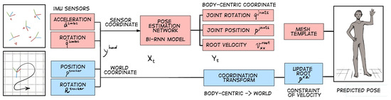
Figure 7.
A brief overview of the instrument for human pose detection. Two types of sensors are used for human pose estimation. IMU sensors are attached to each human limb to measure their inertial data (orientation and acceleration), which are then used as input to the pose estimation network. The method can predict the basic pose of the user’s whole body.
2.9. EMG Sensors Usage for Head Position Estimation
EMG signals can also be utilized to determine the position of the human head. As evidenced by the article [38] authored by Ken-ichi Morishig et al., a model that estimates the continuous motion of the human head from the EMG signals of the neck was created. The model proposed by the authors takes into account not only static but also dynamic effects and predicts well the head-turning movements. To estimate the head direction angle from neck EMG signals, the authors used a linear regression model. It has been demonstrated that the proposed model has the capacity to accurately reconstruct the observed data from neck EMG signals using the TeleHead auditory robot.
Frank L. Brodie et al. [39] developed a compact, cost-effective electronic sensor and alarm system for real-time monitoring of patients’ head position. This instrument is particularly suited to vitreoretinal surgery. The study describes the simulation of gas in the eye following pneumatic retinopexy with pure gaseous sulfur hexafluoride (SF6) initially expanding and then dissipating. The authors created a model of the volume of injected 100% intraocular SF6 gas bubble on days 1, 3, and 5 postoperatively. Of the 36 data points recorded, the sensor functioned properly in 33 (91.7%) of them. The sensor started an alarm every time the bubble went beyond the rupture (n = 15, sensitivity = 100%). Nevertheless, the sensor erroneously sounded an alarm on 3 occasions out of 21, despite the bubble being correctly positioned over the retinal tear (specificity = 86%).
In [40], an evaluation of algorithms for simultaneous estimation of head position and visual focus of attention (VFOA) in a conference room is presented. Head orientation is estimated using the Rao-Blackwell filter to localize the head and estimate its pose. The output of this filter is used in a hidden Markov model (HMM) to estimate people’s VFOA. The detection errors of the Euler angles for two filters, RBPF (Rao-Blackwellized particle filter) and MSPF (multisensor sequential particle filter), are compared.
2.10. Optical Fiber Use for Head Position Estimation
It should be noted that optical fiber based sensors are capable of head position detection. The fields of application of such sensors can be very diverse, including civil engineering, mechanical engineering, aerospace industry, biomedicine, and medicine. However, general approaches using fiber sensors can also be applied to head pose estimation.
The extensive array of fiber optic sensors encompasses devices based on FBGs (fiber Bragg gratings). In the following section, we will cite several literature sources that describe the application of such sensors in various fields and summarize how these types of devices can be applied to head position monitoring.
For example, two types of FBG-based sensing instruments and their applications are presented in [41], which can display a three-dimensional image of the colonoscopy shape on a video screen. The FBG sensors detect the deformation of the wire and reconstruct the shape of the colonoscopy. In [42], Yong-Lae Park et al. describe a biopsy needle equipped with an FBG to measure the bending deflections of the needle as it is inserted into tissues. Two sets of sensors, located at different points along the needle, provide bending profile estimation as well as temperature compensation. A soft manipulator shape monitoring system is presented in [43]. This paper presents a shape detection algorithm based on signals from four optical fibers with induced FBGs inside them. The shape detection algorithm is based on the assumption of piecewise constant curvature and torsion and can convert the curvature and torsion measured by the sensor network into global node positions and orientations. In [44], a numerical and experimental wind tunnel study of aeroelastic wing shape determination using fiber optic sensors is presented. Optical fiber deformation data were used to reconstruct the deformed shape under static conditions, which were then compared with the aeroelastic analysis data. In [45], it is reported that multicore fibers incorporating FBG strain sensors in each core, such as a fiber optic pitch and roll sensor, can be used for pitch and roll angles. The difference in mechanical stress between opposite pairs of gratings depends on the orientation of the fiber in pitch (in the vertical plane) and roll with respect to gravity. In [46], the authors Botsis J. et al. describe the main aspects of using FBG-based sensors as a tool for measuring internal strains. Experimental results of internal elastic strain measurements in different configurations are presented. These data are used to determine three key factors: (a) the coupling forces in a model composite, (b) the strains through the thickness of a layered composite, and (c) the residual stresses in an epoxy resin cylinder. In [47], the authors David Barrera et al. investigate the utilization of long-period gratings (LPGs) to develop a directional curvature sensor. A single LPG was positioned within the outer cores, while an array of three LPGs was situated within the center core. The torsion in multicore fibers can be detected and measured through the maximum attenuation of the LPGs within the outer cores.
In the case of head position monitoring, it is possible to locate optical fibers with single-point FBG on a headgear, for example, on a ski mask. The ski mask does not hide the human face itself, which is important for training pupil detection algorithms while providing the possibility of locating the reference sensors on it. A pair of optical fibers can be located on the sides of the headgear, with another fiber on the back. Thus, the compression/stretching of the fibers with induced FBGs will unambiguously determine the relative change in the head position. By applying the aforementioned algorithms to restore curvature, torsion, or deformation, the patient’s head position can be restored.
In addition to the group of point-wise fiber optic sensors, there is a larger group of distributed fiber optic sensors. The following section will present a review of several works that demonstrate the application of such sensors. This will be followed by a conclusion on how this group of sensors can be applied to the topic of this paper.
In their study [48], authors Roger G. Duncan et al. present the results of a performance test of a monolithic fiber optic array of shape detection sensors. The authors discuss two sensing methods: the first involves the use of FBG, and the second involves the use of intrinsic Rayleigh backscattering of the optical fiber. In [49], three-dimensional distributed shape and position determination were demonstrated using a silica fiber with multiple optical cores. It is reported that the novel helical shape enables the fiber to convert optical frequency domain reflectometry (OFDR) distributed strain measurement data into curvature, torsion, and three-dimensional shape measurements along its entire length.
The methods described in the above references can be applied to head rotation estimation as well. For example, two single-mode fibers can also be positioned on a ski mask. The location of the first is from the edge of the hat on the left side to the edge of the hat on the right side. The location of the second is from the edge of the hat on the back side to the edge of the hat on the top (near the forehead). It is proposed that a non-coherent detection scheme, specifically an amplitude strain sensor, be used. The channels can be read alternately. Prior to commencing the measurement, it is essential to calibrate the sensor by recording the primary back-scattering traces.
Another crucial aspect of vHIT is the detection of pupils’ coordinates. The accuracy of pupil tracking will directly impact the outcomes of the experiment. The following is an overview of sources on pupils’ position detection.
3. Methods of Detecting the Human Pupils’ Position
Pupil detection technologies are conventionally divided into four categories:
- Pupil detection using scleral search coils;
- Infrared oculography;
- Electro-oculography;
- Video oculography.
In this paper, we will cite several articles from the category of infrared oculography but will mainly emphasize video oculography. All the following approaches use camera data as the input.
3.1. Deep Learning Techniques
Let us consider the sources that utilize deep learning. The paper by Braiden Brousseau et al. [50] describes a low-cost remote gaze tracking system that utilizes a smartphone with a built-in infrared illuminator and camera. The developed system employs a three-dimensional gaze estimation model that enables the precise estimation of the point of gaze (PoG) when the head and instruments are unrestricted in their movements. To accurately locate the center of pupil and corneal reflections, the system uses convolutional neural networks along with a new center-of-mass output layer, which increases the system’s robustness to significant changes in the appearance of eye images found in handheld tracking systems. The hybrid approach, which uses artificial illumination, a three-dimensional gaze estimation model, and CNN-based feature extraction, achieved significantly higher accuracy (400%) than existing smartphone eye-tracking systems that employ natural illumination and machine learning techniques for estimation. In the work of Nachiappan Valliappan et al. [51], a three-layer convolutional neural network was used to estimate the position of the patient’s pupils. An RGB (red, green, blue) image from the front camera of a smartphone was fed to the input of the network. It was reported that the average pupil detection error across 26 patients was approximately 0.5 cm, which was comparable to that of the expensive Tobii Pro 2 instrument. The paper also notes that the accuracy of pupil position detection varies depending on the location of the eyes within the frame. Yu Feng et al. [52] present a gaze detection algorithm based on deep neural networks (DNN). The algorithm’s design is illustrated in Figure 8. The authors claim that their model is capable of detecting pupil position with an error of 0.5 degrees and that the frame rate can be maintained at around 30 Hz.
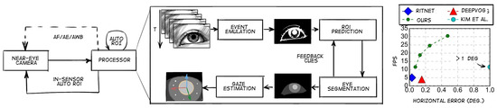
Figure 8.
Left: workflow of the gaze tracking algorithm. The algorithm provides Auto ROI (region of interest) (akin to conventional “3A” in-camera algorithms) by simulating an event camera (an image sensor that responds to local luminance changes) in software and using the events to predict the ROI. Right: the algorithm achieves a gaze accuracy of less than 0.5° (in both horizontal and vertical directions) using only 30 thousand parameters, which is less than other algorithms.
In [53], a real-time gaze tracking system based on active IR illumination is described. This system is used in an interactive graphical display. The system can perform robust and accurate gaze estimation without calibration and with quite significant head movement. The authors introduce a novel gaze calibration method that identifies the mapping of pupil parameters to screen coordinates using generalized regression neural networks (GRNNs). The gaze angle accuracy is approximately 5 degrees horizontally and 10 degrees vertically. In [54], authors Bin Li et al. present a method for estimating eye location from facial images. A set of convolutional neural networks is used to determine the most probable eye region and classify the region as the left or right eye. Initially, the most probable eye location regions are determined, then a first set of convolutional networks detects the correct position of the eyes in the frame and outputs their outline, and a second set of convolutional networks marks the location of the pupils. The presented method is reported to be faster and adaptable to image variations, including changes in ambient lighting, facial occlusions, and changes in image modality. In a study published by Warapon Chinsatit et al. [55], a convolutional neural network-based method for pupil center detection was presented for a wearable gaze estimation system using infrared eye images. The proposed method (Figure 9) employs two CNN models. The first CNN model is used to classify the eye state, while the second is utilized for the detection of pupil center coordinates. The classification model discards images with closed eyes, while the estimation model performs gaze parameter computation only when the input image shows an open eye. The proposed method exhibits high accuracy and has the potential for application in gaze estimation based on wearable devices.
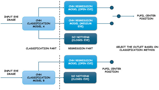
Figure 9.
The proposed two-part CNN model.
The classification models A and B used five convolutional layers and two fully connected layers. For model A, the number of classes is three (open eye, medium eye, closed eye), and for model B, the number of classes is two (closed eye and non-closed eye). Authors reported results with different convolutional kernel sizes (from 11 × 11 to 3 × 3), pooling sizes (from 2 × 2 to 3 × 3), dropout layers, and normalization. For both classification and regression evaluation, authors used leave-one-out cross-validation.
Wolfgang Fuhl et al. propose and evaluate a method based on a dual convolutional neural network architecture [56]. In the initial stage, the model performs a preliminary identification of the pupil position through the use of a convolutional neural network and sub-regions derived from a reduced input image, thereby reducing the computational cost. Subsequently, the second stage employs a second convolutional neural network to refine the initial estimate of the pupil position, utilizing sub-regions obtained from a small window around this estimate. In [57], a region proposal network (RPN) is presented that utilizes convolutional features of the full image in conjunction with a detection network, which enables image processing in 10 milliseconds. RPN is a fully convolutional network that simultaneously predicts object boundaries and estimates the likelihood that an object is located in a given pixel or region. The RPN is trained to predict, with high accuracy, the regions where objects are located in the image. These regions are then fed to the input of the R-CNN (region-based convolutional neural network) to segment the objects in the image. In this case, the RPN is used as an attention mechanism (or so-called attention model). It has been reported that the developed detection system has a frame rate of five frames per second (including all stages) on a GPU (graphics processing unit) while providing state-of-the-art accuracy in detecting objects from public databases. In [58], S. Navaneethan et al. proposed a pupil detection method based on a neural network architecture and many techniques from recently developed popular networks, like CNN. The experimental results demonstrate that the proposed architecture is capable of effectively detecting iris microstructures and provides a stable distinguishing iris representation, with high accuracy. In [59], the authors used the R-CNN (region-based convolutional neural network) algorithm with six layers to estimate the location of the eye. The pupil region was delineated using a Gaussian mixture model. Subsequently, the circular boundary of the pupil region was computed according to five key boundary points. The authors reported that the proposed iris segmentation method achieved an accuracy of 95.49% in the complex CASIA (Chinese Academy of Sciences Institue of Automation) database. In [60], Wang C. et al. propose a highly efficient iris segmentation approach based on deep learning named IrisParseNet. This approach is capable of successfully segmenting the iris even in the presence of high noise in the image. Unlike many previous CNN-based iris segmentation methods that focus solely on predicting accurate iris masks, the authors emphasize that their approach provides a comprehensive solution for iris segmentation. In [61], an algorithm based on an artificial neural network, in conjunction with SVM (support vector machine), is proposed for eye detection. In the proposed algorithm, the neural network is initially trained to discard the non-eye region based on eye feature images and non-eye feature images using a Gabor filter and SVM for dimensionality reduction and efficient classification. Initially, the face is segmented using color space, and then the neural network predicts the eye position. The test results exhibited a 98% probability of accurate detection. In their paper [62], Young-Joo Han et al. proposed a method for eye blink detection or eye tracking on smartphone platforms. Given the limited resources of smartphones, one of the key challenges of eye blink detection is its computational efficiency. Consequently, the authors employed a hybrid approach combining two machine learning methods, SVM and CNN. The authors demonstrate that eye blink detection can be performed efficiently and robustly on smartphones with limited resources. Experimental results on common smartphones indicate that the approach achieves 94.4% accuracy and a processing speed of 22 frames per second.
3.2. SVM Algorithms
It is important to highlight the SVM algorithm, as its implementation is considerably simpler than that of neural networks. As previously mentioned, SVM has been used in conjunction with deep learning models in various sources. SVM has a multitude of applications in detection and classification algorithms, with authors frequently resorting to its use. The combination of the Kalman filter and SVM was explored by the authors in [63], with the algorithm divided into two parts: eye detection and pupil tracking. Eye detection is achieved by concurrently leveraging the bright/dark pupil effect under active IR illumination and the eye appearance structure under ambient illumination through the SVM method. Gaze tracking is divided into two modules. The first module is a conventional tracker with Kalman filtering based on the bright pupil, and the second module is the same SVM designed to verify the detected eyes. In [64], a hybrid eye detection method based on another filter, the gray intensity variance filter (VF) and SVM, is described. VF is used to remove the majority of non-eye regions in the image, thus reducing the number of candidate regions for eyes. Then, the exact regions of the two eyes are easily identified using a trained SVM classifier. Furthermore, the paper evaluates the sensitivity of the obtained parameters in the SVM classifier to the accuracy of eye detection. In [65], an eye detection method is proposed that can detect the location of eyes in face images captured in different head positions. The method consists of two steps: candidate eye detection and candidate eye verification. The extracted candidate regions are then verified using an SVM method based on a feature-level combination of histogram of oriented gradients (HOG) and average pixel intensity features. In [66], a system study is presented that can detect and recognize a person in three-dimensional space automatically and without human-face interaction. This system is based on a learning algorithm (using SVM) for human classification and recognition. This study presents a methodology for automatic three-dimensional face recognition using anthropometric proportions and measurements to detect and select a region of interest that is not affected by facial expression.
3.3. Color Histograms, Template Matching
We will highlight methods based on color histograms and template matching. In [67], a novel application of an optical sensor for a computer mouse is presented. The optical mouse is utilized as the primary low-cost IR vision system in a proposed novel device mounted on the human head, which is designed to control a computer by means of eye movement. A series of performance tests were conducted, during which the average pupil detection error was 0.34 pixels, with successful detection in 82.6% of all mouse events. In [68], Ankur Raj et al. present an open-source embedded system for wearable non-invasive real-time pupil detection on a wearable device. In addition to the hardware, a pupil detection algorithm was developed that operates using edge analysis, with a rate of 30 frames per second and a runtime of 54 ms at 480 × 640 resolution and 23 ms at 240 × 320 resolution. The algorithm exhibited an average cumulative error of 5.3368 pixels when tested. In [69], a rapid and precise method, designated as SET (Sinusoidal Eye Tracker), has been developed, rendering it suitable for use in natural environments with dynamically changing and even exceedingly high illuminance levels. The SET offers a cost-effective eye-tracking solution that is capable of delivering high performance even in challenging environments. In [70], Gunjan Gautam et al. present an adaptive pupil localization method based on circularity criteria. The method begins with gray-level inversion, which is applied to suppress reflections. This is followed by contrast estimation based on a gray-level co-occurrence matrix (GLCM). Correction, contrast adjustment, adaptive threshold filtering, and some morphological operations are then performed to obtain a binary image with a small number of regions. Finally, for each of these regions, a circularity index is computed, and the region with the largest circularity index, which also exceeds a given threshold, is identified as the pupil. The work of [71] contains a method that includes the localization of pupillary and limbic iris boundaries. The proposed algorithm takes into account the noise region that is detected in different parts of the eye image, such as light reflection. A comparison of the proposed algorithm with state-of-the-art iris localization algorithms revealed a notable enhancement in segmentation accuracy, accompanied by a reduction in computational complexity. In [72], an iris and pupil segmentation scheme is proposed, which includes the following steps: first, a set of initial pixels in a preprocessed eye image are adaptively labeled. Then, a dual scheme based on the circu-differential accumulator (CDA) and gray statistics is applied to localize the coarse region of the iris and pupil accordingly. Next, a refined estimate of the limbic boundary is extracted. Subsequently, the iris boundaries are regularized using the Fourier series. Finally, eyelids are localized using PDA (para-differential accumulator) and eyelashes and reflections are also adaptively localized in polar iris coordinates. In [73], a peak detection algorithm is proposed for accurate pupil location. The proposed peak detection algorithm determines the optimal peak, which helps to localize the pupil. The amplitude value of the optimal peak is used as an auxiliary value to calculate the threshold value. The threshold value is used to partition the image into distinct gray levels or, in the most basic instance, to binarize the pixel values of the image. Ultimately, the Canny edge detector is applied to the binary image with the objective of localizing the pupil within the image. A novel approach to estimating the pupil and its glare for a gaze-tracking system utilizing a wearable camera sensor and a near-infrared LED matrix is proposed in [74]. An enhanced least squares method is proposed for detecting the pupil boundary. Furthermore, the developed enhanced least squares method is employed to address the deformation issue of the Gaussian function, thereby enabling the calculation of the glare center of the eye. In [75], a novel methodology for automatic pupil and iris localization is presented. The proposed algorithm employs an eccentricity-based halving method to localize the pupil. This method searches for the region with the highest probability of containing a pupil. The iris is localized in two steps. In the first step, the iris image is segmented along the direction of interest, and the region of interest is extracted. In the second step, angular lines in the region of interest are extracted. These lines are used to determine the edge points of the outer boundary of the iris, which is performed by calculating the gradient of the lines. In their study, Saransh Shah et al. [76] present a new iris segmentation scheme that employs geodesic active contours (GAC) to extract the iris from surrounding structures. The proposed scheme detects iris texture in an iterative manner, guided by both local and global image properties. The authors observe an improvement in the matching accuracy of the iris detection system when the proposed segmentation algorithm is applied. In [77], an iris localization method based on intensity value analysis is described. In the proposed scheme, the inner boundary of the iris is computed by identifying the center and radius of the pupil through the application of two methods. In the first method, the selected region is subjected to adaptive binarization, with the center of gravity of the region subsequently employed to derive the pupil parameters. In the second method, the edges are processed in order to identify the radius and center of the pupil. For the outer iris boundary, the area within which the outer iris boundary is located is computed. The excess points near the estimated iris boundary are filtered using the Mahalanobis distance, and the remaining points are used to obtain the outer circumference of the iris. Similarly, the points for the upper and lower eyelids are determined in a manner analogous to that utilized for the outer iris boundary. Subsequently, the selected points are statistically approximated to obtain parabolas, and the eyelashes are removed from the image in order to completely localize the iris. Mu-Chun Su et al. [78] presented a set of methods integrated into a low-loss eye-tracking system. The authors report on their use of the eye tracking system to implement an “eye mouse” to provide computer access for individuals with disabilities. The proposed eye mouse allows individuals with disabilities to use their eye movements to control computers. A five-step algorithm is developed to estimate the directions of eye movements and then use the direction information to control the computer. The authors conducted a series of experiments to validate the performance of the eye-tracking system. In [79], a robust algorithm for eye recognition in gray images is presented. The primary objective of the method is to integrate the respective advantages of two methods, the feature-based method and the template-based method, while overcoming their respective disadvantages. After identifying the face region, the feature-based method is employed to detect two uneven regions of both eyes. Subsequently, the center of the iris is detected within these two uneven regions via the template matching-based method. The experimental outcomes obtained with individuals who do not wear glasses demonstrate that the proposed approach is not only robust but also highly effective. In [80], the authors propose an approach for accurate and robust eye center localization using image gradients. They introduce a simple target function that consists only of point products. The maximum of this function corresponds to the location where most of the gradient vectors intersect and, hence, to the eye center. The method is invariant to changes in scale, pose, contrast, and illumination. In [81], a new approach to detecting landmarks in faces is proposed. The authors present an inner product detector (IPD) based on correlation filters. In [82], an approach for detecting and tracking eye movements in videos (Figure 10) using Haar-like features is proposed. The contributions of this work can be divided into two parts. The first contribution is that filters have been trained that can efficiently and accurately detect eye locations without background and skin color constraints. The second contribution is the creation of frameworks (named tracker and LK optictracker by the authors) that can track eyes without state constraints. Experimental results demonstrate the accuracy aspects and real-time applicability of the proposed approach.
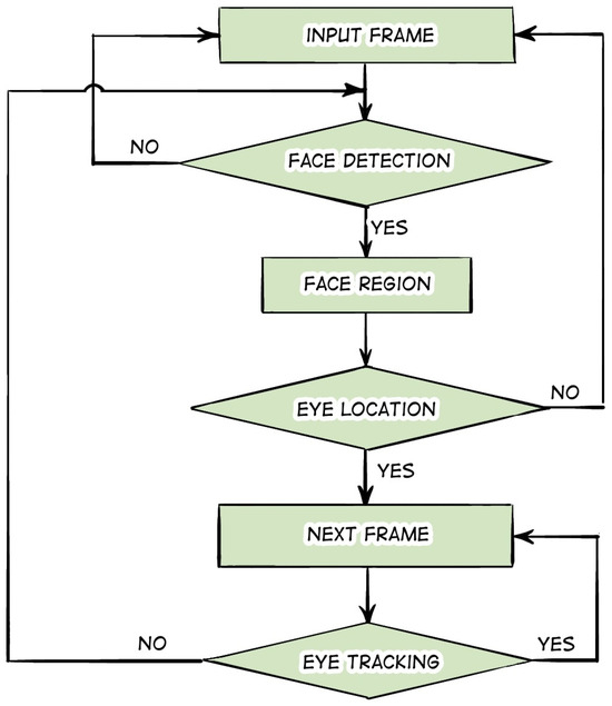
Figure 10.
Scheme for detection and tracking of eye movements using Haar-like features.
In [83], a method for automatically locating pupils in images (even with low resolution) with human faces positioned nearly frontally is presented. In particular, pupils are localized using a two-step procedure: first, self-similarity information (in the regions where the pupils are located) is extracted by taking into account the variability in the appearance of local regions, and then the information is combined with circular shape estimation based on a modified version of the circle Hough transform. In [84], a device for tracking and registering pupils in a video displayed on a smartphone screen is proposed. The device consists of a case for fixing the smartphone in the eye region, a Bluetooth joystick for launching the application and initial calibration, and the smartphone itself. Given the camera location, the coordinates of the frame area where the eye image is located are calculated. The eye area is copied to a buffer for further processing. Pupil center estimation is performed exclusively within the buffer and not the entire received frame. This is performed to enhance the efficacy of the algorithm. The Fabian Timm and Erhard Barth method is employed to determine the pupil center in real-time, for instance, within the video stream.
3.4. Geometric Transformations
Geometric transformation-based methods are also employed in human eye tracking. For instance, [85] presents an accurate algorithm for calculating pupil position and iris size in natural light. This algorithm is based on sets of positive and negative oblique projections. The intersection of a pair of these projections in the estimated eye region defined using image binarization yields the pupil position. Experimental results demonstrate that the algorithm is robust to changes in illumination and the presence of glasses in humans. Moreover, the authors report that compared to a system based on a monocular camera, the error in the distance between the label points and the gaze location is reduced by 5 pixels, and the variance is reduced by 3 pixels. With a user-screen distance of 60 to 80 cm, the accuracy can reach 1.5 to 2.2 degrees. In [86], the authors propose a real-time user gaze estimation system that does not require human-dependent calibration. It can also account for changes in illumination and head position and can handle a wide range of camera-to-person distances. The solution is based on a data processing method that processes images from a laptop’s built-in camera. Real-time performance is achieved by combining head position information with eye geometric features to train a machine learning algorithm. The method has been validated on a dataset of user images. Seokhoon Kang et al. [87] describe an optimal interpretation of screen resolution for gaze estimation according to the position in three-dimensional space between the user and the camera. The screen resolution is directly related to the pupil movement distance in pixels from edge to edge of the display. In addition, the ratio of the three-dimensional position between the user and the camera determines the resolution of the resulting image. In the aforementioned paper [87], a gaze estimation technique utilizing a single camera is employed to demonstrate the maximum image resolution as a function of 3D position. The average accuracy of gaze estimation using the maximum image resolution is 68.39%. In [88], an eye-tracking procedure is presented that provides a non-invasive method to detect the pupils of an object in real-time in a sequence of frames captured by inexpensive equipment. It is reported that the procedure can be readily adapted to any eye-tracking application. The identification of eye pupils is performed using a hierarchical optimal segmentation procedure, context zoning of the image, which determines the position of the eyes, and further binarization, which extracts the pupil coordinates. In the described paper, the necessity for an eye movement model to predict future eye position is negated by the rapidity of the initial step in the procedure, which enables the updating of eye position from frame to frame.
3.5. Decision Trees
Furthermore, there are examples of the use of decision trees in pupil detection, in particular, the paper by Amine Kacete et al. [89]. The authors propose an approach based on Hough regression, which is demonstrated to be highly robust to illumination, scale, eye movements, and large changes in head position. This approach also yields significant improvement over a wide range of state-of-the-art methods. In [90], a method for quantifying decision-making in the diagnosis of strabismus disease is presented. An infrared camera with IR illumination is used to capture the patient’s eyes. The three main processing steps in the proposed algorithm are as follows: (i) eye recognition using Haar-like features combined with AdaBoost classifier; (ii) the authors have developed a new method to determine the pupil ellipse in an image frame. This method uses a linear integral to determine the pupil ellipse in real-time; (iii) estimation of pupil normal vector based on segmented pupil ellipse parameters. All three methods were evaluated on real human eye data and on an eye model. In [91], Nenad Markuš et al. describe an eye pupil localization method based on an ensemble of random regression tree models and use several publicly available datasets for its quantitative and qualitative evaluation. This method corresponds well to the claimed prior art and is capable of functioning in real-time on computationally limited hardware such as mobile devices. In [92], the authors describe a method for simultaneous eye detection and eye state estimation. The method described in the paper employs a cascade regression framework to iteratively estimate the location of an eye and the probability that the eye is covered by an eyelid. At each iteration of the cascade regression, image elements from the center of the eye, as well as contextual image elements from the eyelids and corners of the eyes, are jointly used to estimate the eye location and the probability of the eye being open. The probability of whether an eye is open is used by the authors to estimate the most likely eye state. The combination of real and artificial images for training further improves performance by using this method of learning by synthesis.
3.6. Viola–Jones Algorithm
In both the case of head pose estimation and pupil detection, the Viola–Jones algorithm is a relevant approach. In her paper [93] on detecting pupil coordinates using the Viola–Jones algorithm and artificial neural networks, Farah Nadia Ibrahim emphasizes the importance of calibration points set on the user’s screen for the eye-tracking process. The calibration process is initiated by tracking the user’s attention to four points on the screen, which are subsequently replaced by nine points in different regions of the screen. These points are placed in front of the user. The iris circle is then detected to determine the coordinates of the center of the eye. The coordinates of the eye center are extracted using the Viola–Jones algorithm. These coordinates are then used as a dataset to train the gaze location using a neural network algorithm. The results demonstrate that a combination of both algorithms is an effective approach for detecting the center of the eye. In [94], the focus is on eye detection, calculating a person’s blink rate, and then determining their level of attentiveness. Using an algorithm based on the Viola–Jones approach, the authors determined the blink rate, which, if deviating from an average threshold level, indicated that the person was tired or lacked attention. The accuracy of eye blink detection was 87%, while simple pupil position detection achieved an accuracy of 97%.
3.7. Classical Machine Learning Methods
Let us consider the application of classical machine learning tools. Methods such as k-nearest neighbors, naive Bayesian method, and PCA (principle component analysis) are also used in pupil tracking. In their paper on emotion recognition and human intention prediction, authors Junfeng Yao, Qingqi Hong, and Jun Li [95] capture and analyze the behavior patterns of human gaze and head movement and classify them into different categories. Furthermore, the paper develops an eye object movement attention model and an eye object feature preference model based on the gaze behavior of different individuals using machine learning algorithms. These models are employed to predict the object of people’s attention. Additionally, gaze behavior and head movement models can be utilized as information in computing human emotional states based on the PAD (Pleasure, Arousal, Dominance) affective computing model. The methodology presented in this paper employs gaze behavior and head movement analysis to assess human emotions and cognitive status. It elucidates the cognitive information conveyed by human eyes and enhances the efficiency of human–computer interaction in diverse contexts. The paper employs a naive Bayesian algorithm as a concrete machine learning tool. Lech Świrski et al., in their paper [96], present a novel algorithm for real-time tracking of dark pupils. The approach described uses a Haar-like feature detector to approximate the location of the pupil, performs k-means segmentation in the surrounding region to refine the pupil center, and fits an ellipse to the pupil using an ellipse fitting algorithm subject to random sampling. In [97], a new technology designed to assist people with disabilities is presented. A discrete eye tracking system recognizes the user’s command from a random controlled eye movement. The user wears a device on his head in the form of glasses with a video camera attached to them. The recognition principle is based on the extraction of eigenvectors from the image. The system was tested with three online applications. The first is controlling a mobile robot in a maze; the second application is a text writing program, “EyeWriter”; and the third is a computer game. More than 25 commands per second can be generated with the presented eye-tracking system.
3.8. CHT Algorithm
The authors Alexandru Pasarica et al. [98] compare two eye-tracking algorithms: Circular Hough Transform (CHT) and Starburst. Both of them consist of the following steps:
- Obtaining an image of the eye;
- Image filtering;
- Calibration of the system by nine reference points;
- Detecting the coordinates of the pupil center in each frame provided by the IR video camera;
- Matching the detected pupil center of the eye image with the cursor movement on the user’s screen;
- Optimization of the algorithm in order to stabilize the cursor movement on the user’s screen using different techniques: real-time filtering and burst removal.
The optimal frame rate for the algorithms was 10–15 Hz. The resolution of the video camera used for data recording was 640 × 480 pixels. The authors noted that both algorithms demonstrated satisfactory performance, with the Starburst algorithm producing more accurate values of pupil movement coordinates.
3.9. RASNAC Algorithm
Tossy Tomas et al. describe a system [99] that presents a method called RANSAC (Random Sample Consensus) for fitting an ellipse around non-circular iris boundaries. This method allows for a more accurate definition of iris boundaries than methods based on the Hough transform. The Daugman rubber-sheet model was also employed to normalize the iris and elliptical unfolding, as well as a correlation filter-based matching technique to estimate intra-class and inter-class distances. PSR (Peak SideLobe Ratio) is a similarity measure utilized for template matching. This enhances the recognition process in comparison to Daugman’s method.
4. Conclusions and Perspectives
Based on the above review, it can be concluded that the set of architectures and algorithms employed in both head pose estimation and pupil position detection methods is extensive. Therefore, in order to achieve optimal results, it is necessary to select those models that will yield the most satisfactory outcomes in relation to the specific technical task at hand. The following two tables present a comparative analysis of the various detection methods employed for the estimation of head position and pupil location.
As we have presented a range of methods for estimating head posture and detecting pupils, we provide Table 2 and Table 3 for comparing them. In fact, it is difficult to evaluate each approach for head posture estimation by a common metric. So, it is for a pupil detection approach comparison. Due to the completely different mathematics and real application scenarios of each reviewed method, different authors provide different metrics to evaluate their methods. Thus, we provide two common metrics, the best accuracy and the best time performance, which are suitable for our scenario of human pre-stroke condition detection. The suitability of each method is evaluated based on rough calculations. The maximum angular velocities of head and eye movements are assumed to be five radians per second, based on [100]. Furthermore, it is assumed that the error of velocity measurement should be smaller, with a maximum permissible error of 0.5 rad/s or 30 °/s. Let us assume that the camera discredit rate is 100 frames per second. Therefore, the maximum allowable error is 0.005 radians per frame or 0.3 degrees per frame. As a result of a rough calculation, we have obtained a criterion that will enable us to categorize all methods into those that are suitable and those that are unsuitable.
Table 2.
Comparison of head pose estimation technologies by 2 metrics.
Table 3.
Comparison of pupil position detection technologies by 2 metrics.
Table 3 presents a comparison of pupil detection techniques. It should be noted that the SVM algorithm is also considered a classical machine learning method. However, it was considered separately with several types of filtering, and it was decided to place the SVM algorithm in a separate row in Table 3.
The aforementioned tables draw the conclusion as to which methods can be used in our future research and be compared with each other in human pre-stroke condition detection scenarios. In further works, we will also study the practical feasibility of the methods that have been outlined, as it is necessary to execute each of these methods using the same instrument.
It is our contention that the advancement of technology will be contingent upon the enhancement of algorithms of the hybrid type. This may entail the incorporation of neural network approaches and methods of analytical data processing. For instance, our experience indicates that processing optical data with correlation algorithms [101,102] and nonlinear filters [103,104] can significantly enhance the signal-to-noise ratio. Furthermore, the combined use of these approaches with machine learning methods can yield more accurate results than if these methods were applied separately [105,106]. As technology is integrated into gadgets and mobile devices, issues related to varying, mostly low-light conditions will make algorithms for handling data with low signal-to-noise ratios particularly relevant. These algorithms will have to be utilized before neural network approaches can be applied.
As for the process of training neural networks designed to detect pupils and estimate the position of the head, it is necessary to use quite impressive amounts of data for this task. It is unlikely that game controllers, helmets, handheld gyroscopes, and other similar devices will be suitable for achieving this goal, as their presence on the head or face of a person significantly alters the image. The key to success in the future will be sensor optical fibers, which can contain several light-guiding cores and have an outer diameter of less than 250 µm [107,108,109]. In the absence of special coloring, these fibers can be made to appear practically invisible on a person’s face or head. In order to circumvent the issue of accurately locating a fiber sensor, for instance, a fiber Bragg grating, we propose utilizing the method of optical frequency domain reflectometry (OFDR). This approach enables the registration of microdeformations along the entire length of the fiber with a spatial resolution that is significantly less than 1 mm [110,111,112]. A substantial quantity of data on deformations at each fiber point will permit the accurate reconstruction of the head rotation angle, excluding movements along other axes from the calculation. The approach of optical frequency domain reflectometry is actively employed for the shape detection of objects of various types, thus enabling the methods of data interpretation to be developed at a relatively rapid pace on the basis of an impressive theoretical and practical background outlined in state-of-the-art studies [113,114]. Despite all these advantages of the optical frequency domain reflectometry, when using this approach, researchers run the risk of facing two problems: the sensing speed may be insufficient for the acquisition of the training data, as well as some difficulties in interpreting the signals. However, these two problems can be solved by modifying the reflectometer’s circuit and by collecting and studying statistics accordingly.
Regarding our future setup for vHIT data collection, we list some challenges which we expect to meet while performing the experiment (Figure 11).
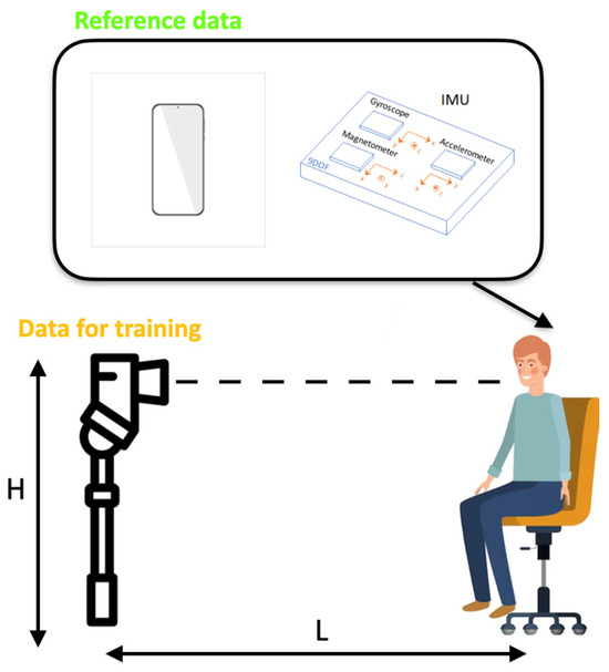
Figure 11.
Our brief scheme for future data collection.
We plan to use the IMU sensor signals as a reference to obtain the head position and create a stable target vector. Simultaneously, we will record the real vHIT tests on a conventional camera. For reference IMU data, the challenge is to enable the most stable instrument for raw IMU data processing into quaternions states at each epoch (time). For the training data recorded by a camera, there should be some strict rules, which will set L—the distance between the patient and the camera, and H—the height of the camera. Moreover, we should find the threshold parameters of such cameras as FPS, resolution, and bit rate, below which the system performance will decrease. Finally, our general aim is to develop a fast and effective method to track the pupils’ movements so that we will have a stable target vector for training.
It is our hope that this review will help other researchers and engineers in identifying the most significant contributions and determining the optimal approach for developing effective diagnostic methods that can be readily accessed by all patients, given the pervasiveness of smartphones and laptops.
Author Contributions
G.D.M.: writing, paper design (All sections); A.A.K.: writing (Section 1 and Section 4); F.L.B.: writing (Section 1 and Section 4), proofreading; Y.A.K.: writing, (Section 1, Section 2.10 and Section 4), paper design, proofreading; D.P.S.: visualization, paper design, proofreading; V.P.: scientific supervision. All authors have read and agreed to the published version of the manuscript.
Funding
This research was performed as a part of State Assignment No. 124020600009-2.
Data Availability Statement
Not applicable.
Conflicts of Interest
The authors declare no conflicts of interest.
References
- Strupp, M.; Bisdorff, A.; Furman, J.; Hornibrook, J.; Jahn, K.; Maire, R.; Newman-Toker, D.; Magnusson, M. Acute unilateral vestibulopathy/vestibular neuritis: Diagnostic criteria. J. Vestib. Res. 2022, 32, 389–406. [Google Scholar] [CrossRef] [PubMed]
- Kim, J.S.; Newman-Toker, D.E.; Kerber, K.A.; Jahn, K.; Bertholon, P.; Waterston, J.; Lee, H.; Bisdorff, A.; Strupp, M. Vascular vertigo and dizziness: Diagnostic criteria. J. Vestib. Res. 2022, 32, 205–222. [Google Scholar] [CrossRef]
- Parfenov, V.A.; Kulesh, A.A.; Demin, D.A.; Guseva, A.L.; Vinogradov, O.I. Vestibular vertigo in stroke and vestibular neuronitis. S.S. Korsakov J. Neurol. Psychiatry 2021, 121, 41–49. [Google Scholar] [CrossRef]
- Kulesh, A.A.; Dyomin, D.A.; Guseva, A.L.; Vinogradov, O.I.; Parfyonov, V.A. Vestibular vertigo in emergency neurology. Russ. Neurol. J. 2021, 26, 50–59. [Google Scholar] [CrossRef]
- Newman-Toker, D.E.; Curthoys, I.S.; Halmagyi, G.M. Diagnosing Stroke in Acute Vertigo: The HINTS Family of Eye Movement Tests and the Future of the “Eye ECG”. In Semin Neurology; Thieme Medical Publishers: New York, NY, USA, 2015; Volume 35, pp. 506–521. [Google Scholar] [CrossRef]
- Nham, B.; Wang, C.; Reid, N.; Calic, Z.; Kwok, B.Y.C.; Black, D.A.; Bradshaw, A.; Halmagyi, G.; Welgampola, M.S. Modern vestibular tests can accurately separate stroke and vestibular neuritis. J. Neurol. 2023, 270, 2031–2041. [Google Scholar] [CrossRef]
- Ulmer, E.; Chays, A. «Head impulse test de curthoys & halmagyi»: Un dispositif d’analyse. In Annales d’Otolaryngologie et de Chirurgie Cervico-Faciale; Elsevier Masson: Paris, Fance, 2005; Volume 122, pp. 84–90. [Google Scholar]
- Rasheed, Z.; Ma, Y.-K.; Ullah, I.; Al-Khasawneh, M.; Almutairi, S.S.; Abohashrh, M. Integrating Convolutional Neural Networks with Attention Mechanisms for Magnetic Resonance Imaging-Based Classification of Brain Tumors. Bioengineering 2024, 11, 701. [Google Scholar] [CrossRef] [PubMed]
- Ahmad, I.; Yao, C.; Ullah, I.; Li, L.; Chen, Y.; Liu, Z.; Chen, S. An efficient feature selection and explainable classification method for EEG-based epileptic seizure detection. J. Inf. Secur. Appl. 2024, 80, 103654. [Google Scholar] [CrossRef]
- Ghaderzadeh, M.; Asadi, F.; Ghorbani, N.R.; Almasi, S.; Taami, T. Toward artificial intelligence (AI) applications in the determination of COVID-19 infection severity: Considering AI as a disease control strategy in future pandemics. Iran. J. Blood Cancer 2023, 15, 93–111. [Google Scholar] [CrossRef]
- Fasihfar, Z.; Rokhsati, H.; Sadeghsalehi, H.; Ghaderzadeh, M.; Gheisari, M. AI-driven malaria diagnosis: Developing a robust model for accurate detection and classification of malaria parasites. Iran. J. Blood Cancer 2023, 15, 112–124. [Google Scholar] [CrossRef]
- Jiang, Y.; Sadeqi, A.; Miller, E.L.; Sonkusale, S. Head motion classification using thread-based sensor and machine learning algorithm. Sci Rep. 2021, 11, 2646. [Google Scholar] [CrossRef]
- Abate, A.F.; Barra, P.; Pero, C.; Tucci, M. Head pose estimation by regression algorithm. Pattern Recognit. Lett. 2020, 140, 179–185. [Google Scholar] [CrossRef]
- Cao, Y.; Liu, Y. Head pose estimation algorithm based on deep learning. In Proceedings of the AIP Conference Proceedings, Hangzhou, China, 8 May 2017; Volume 1839, p. 020144. [Google Scholar] [CrossRef]
- Zhou, Y.; Gregson, J. WHENet: Real-time Fine-Grained Estimation for Wide Range Head Pose. arXiv 2020, arXiv:2005.10353. [Google Scholar]
- Ruiz, N.; Chong, E.; Rehg, J.M. Fine-Grained Head Pose Estimation Without Keypoints. In Proceedings of the IEEE conference on Computer Vision and Pattern Recognition Workshops, Salt Lake City, UT, USA, 18–22 June 2018; Georgia Institute of Technology: Atlanta, GA, USA, 2018. [Google Scholar]
- Yu, J.; Scheck, T.; Seidel, R.; Adya, Y.; Nandi, D.; Hirtz, G. Human Pose Estimation in Monocular Omnidirectional Top-View Images. In Proceedings of the IEEE/CVF Conference on Computer Vision and Pattern Recognition, Vancouver, BC, Canada, 17–24 June 2023; Chemnitz University of Technology: Chemnitz, Germany. [Google Scholar]
- Khan, K.; Mauro, M.; Migliorati, P.; Leonardi, R. Head pose estimation through multi-class face segmentation. In Proceedings of the IEEE International Conference on Multimedia and Expo (ICME), Hong Kong, China, 10–14 July 2017. [Google Scholar] [CrossRef]
- Xu, X.; Kakadiaris, I.A. Joint Head Pose Estimation and Face Alignment Framework Using Global and Local CNN Features. In Proceedings of the 12th IEEE Conference on Automatic Face and Gesture Recognition, Washington, DC, USA, 30 May–3 June 2017. [Google Scholar] [CrossRef]
- Song, H.; Geng, T.; Xie, M. An multi-task head pose estimation algorithm. In Proceedings of the 5th Asian Conference on Artificial Intelligence Technology (ACAIT), Haikou, China, 29–31 October 2021. [Google Scholar] [CrossRef]
- Khan, K.; Ali, J.; Ahmad, K.; Gul, A.; Sarwar, G.; Khan, S.; Ta, Q.T.H.; Chung, T.-S.; Attique, M. 3D Head Pose Estimation through Facial Features and Deep Convolutional Neural Networks. Comput. Mater. Contin. 2021, 66, 1745–1755. [Google Scholar] [CrossRef]
- Borghi, G.; Fabbri, M.; Vezzani, R.; Calderara, S.; Cucchiara, R. Face-from-Depth for Head Pose Estimation on Depth Images. IEEE Trans. Pattern Anal. Mach. Intell. 2018, 42, 596–609. [Google Scholar] [CrossRef]
- Paggio, P.; Gatt, A.; Klinge, R. Automatic Detection and Classification of Head Movements in Face-to-Face Conversations. In Proceedings of the Workshop on People in Language, Vision and the Mind, Marseille, France, 11–16 May 2020; pp. 15–21. [Google Scholar]
- Han, J.; Liu, Y. Head posture detection with embedded attention model. IOP Conf. Ser. Mater. Sci. Eng. 2020, 782, 032003. [Google Scholar] [CrossRef]
- La Cascia, M.; Sclaroff, S.; Athitsos, V. Head posture detection with embedded attention model. IEEE Trans. Pattern Anal. Mach. Intell. 2000, 22, 322–336. [Google Scholar] [CrossRef]
- Wenzhu, S.; Jianping, C.; Zhongyun, S.; Guotao, Z.; Shisheng, Y. Head Posture Recognition Method Based on POSIT Algorithm. J. Phys. Conf. Ser. 2020, 1642, 012017. [Google Scholar] [CrossRef]
- Yuan, H.; Li, M.; Hou, J.; Xiao, J. Single Image based Head Pose Estimation with Spherical Parameterization and 3D Morphing. Pattern Recognit. 2020, 103, 107316. [Google Scholar] [CrossRef]
- Fanelli, G.; Weise, T.; Gall, J.; Van Gool, L. Real Time Head Pose Estimation from Consumer Depth Cameras. In Pattern Recognition; Springer: Berlin/Heidelberg, Germany, 2011; pp. 101–110. [Google Scholar]
- Kim, H.; Lee, S.-H.; Sohn, M.-K.; Kim, D.-J. Illumination invariant head pose estimation using random forests classifier and binary pattern run length matrix. Hum.-Centric Comput. Inf. Sci. 2014, 4, 9. [Google Scholar] [CrossRef]
- Li, X.; Chen, H.; Chen, Q. A head pose detection algorithm based on template match. In Proceedings of the 2012 IEEE Fifth International Conference on Advanced Computational Intelligence (ICACI), Nanjing, China, 18–20 October 2012. [Google Scholar] [CrossRef]
- Lavergne, A. Computer Vision System for Head Movement Detection and Tracking. Master’s Thesis, University of British Columbia, Kelowna, BC, Canada, 1999. [Google Scholar]
- Chen, S.; Bremond, F.; Nguyen, H.; Thomas, H. Exploring Depth Information for Head Detection with Depth Images. In Proceedings of the AVSS 2016-13th International Conference on Advanced Video and Signal-Based Surveillance, Colorado Springs, CO, USA, 23–26 August 2016; ffhal-01414757. [Google Scholar]
- Saeed, A.; Al-Hamadi, A.; Handrich, S. Advancement in the head pose estimation via depth-based face spotting. In Proceedings of the 2016 IEEE Symposium Series on Computational Intelligence (SSCI), Athens, Greece, 6–9 December 2016. [Google Scholar]
- Neto, E.N.A.; Barreto, R.M.; Duarte, R.M.; Magalhaes, J.P.; Bastos, C.A.; Ren, T.I.; Cavalcanti, G.D. Real-Time Head. Pose Estimation for Mobile Devices. In Intelligent Data Engineering and Automated Learning-IDEAL 2012; Springer: Berlin/Heidelberg, Germany, 2012; pp. 467–474. [Google Scholar]
- Al-Azzawi, S.S.; Khaksar, S.; Hadi, E.K.; Agrawal, H.; Murray, I. HeadUp: A Low-Cost Solution for Tracking Head Movement of Children with Cerebral Palsy Using IMU. Sensors 2021, 21, 8148. [Google Scholar] [CrossRef] [PubMed]
- Benedetto, M.; Gagliardi, A.; Buonocunto, P.; Buttazzo, G. A Real-Time Head-Tracking Android Application Using Inertial Sensors. In Proceedings of the MOBILITY 2016-6th International Conference on Mobile Services, Resources, and Users, Valencia, Spain, 22–26 May 2016. [Google Scholar]
- Kim, M.; Lee, S. Fusion Poser: 3D Human Pose Estimation Using Sparse IMUs and Head Trackers in Real Time. Sensors 2022, 22, 4846. [Google Scholar] [CrossRef] [PubMed]
- Morishige, K.-I.; Kurokawa, T.; Kinoshita, M.; Takano, H.; Hirahara, T. Prediction of head-rotation movements using neck EMG signals for auditory tele-existence robot “TeleHead”. In Proceedings of the RO-MAN 2009-The 18th IEEE International Symposium on Robot and Human Interactive Communication, Toyama, Japan, 27 September–2 October 2009. [Google Scholar]
- Brodie, F.L.; Woo, K.Y.; Balakrishna, A.; Choo, H.; Grubbs, R.H. Validation of sensor for postoperative positioning with intraocular gas. Clin. Ophthalmol. 2016, 10, 955–960. [Google Scholar] [CrossRef] [PubMed]
- Ba, S.O.; Odobez, J.M. Head Pose Tracking and Focus of Attention Recognition Algorithms in Meeting Rooms. In Proceedings of the Multimodal Technologies for Perception of Humans, First International Evaluation Workshop on Classification of Events, Activities and Relationships, CLEAR 2006, Southampton, UK, 6–7 April 2006. [Google Scholar]
- Lunwei, Z.; Jinwu, Q.; Linyong, S.; Yanan, Z. FBG sensor devices for spatial shape detection of intelligent colonoscope. In Proceedings of the IEEE International Conference on Robotics and Automation, New Orleans, LA, USA, 26 April–1 May 2004. [Google Scholar] [CrossRef]
- Park, Y.L.; Elayaperumal, S.; Daniel, B.; Ryu, S.C.; Shin, M.; Savall, J.; Black, R.J.; Moslehi, B.; Cutkosky, M.R. Real-Time Estimation of Three-Dimensional Needle Shape and Deflection for MRI-Guided Interventions. IEEE ASME Trans. Mechatron. 2010, 15, 906–915. [Google Scholar] [PubMed]
- Wang, H.; Zhang, R.; Chen, W.; Liang, X.; Pfeifer, R. Shape Detection Algorithm for Soft Manipulator Based on Fiber Bragg Gratings. IEEE/ASME Trans. Mechatron. 2016, 21, 2977–2982. [Google Scholar] [CrossRef]
- Freydin, M.; Rattner, M.K.; Raveh, D.E.; Kressel, I.; Davidi, R.; Tur, M. Fiber-Optics-Based Aeroelastic Shape Sensing. AIAA J. 2019, 57, 5094–5103. [Google Scholar] [CrossRef]
- MacPherson, W.N.; Flockhart, G.M.H.; Maier, R.R.J.; Barton, J.S.; Jones, J.D.C.; Zhao, D.; Zhang, L.; Bennion, I. Pitch and roll sensing using fibre Bragg gratings in multicore fibre. Meas. Sci. Technol. 2004, 15, 1642–1646. [Google Scholar] [CrossRef]
- Botsis, J.; Humbert, L.; Colpo, F.; Giaccari, P. Embedded fiber Bragg grating sensor for internal strain measurements in polymeric materials. Opt. Lasers Eng. 2005, 43, 491–510. [Google Scholar] [CrossRef]
- Barrera, D.; Madrigal, J.; Sales, S. Long Period Gratings in Multicore Optical Fibers for Directional Curvature Sensor Implementation. J. Light. Technol. 2017, 36, 1063–1068. [Google Scholar] [CrossRef]
- Duncan, R.G.; Froggatt, M.E.; Kreger, S.T.; Seeley, R.J.; Gifford, D.K.; Sang, A.K.; Wolfe, M.S. High-accuracy fiber-optic shape sensing. In Proceedings of the Sensor Systems and Networks: Phenomena, Technology, and Applications for NDE and Health Monitoring 2007, San Diego, CA, USA, 19–21 March 2007. [Google Scholar]
- Lally, E.M.; Reaves, M.; Horrell, E.; Klute, S.; Froggatt, M.E. Fiber optic shape sensing for monitoring of flexible structures. In Proceedings of the SPIE, San Diego, CA, USA, 6 April 2012; Volume 8345. [Google Scholar]
- Brousseau, B.; Rose, J.; Eizenman, M. Hybrid Eye-Tracking on a Smartphone with CNN Feature Extraction and an Infrared 3D Model. Sensors 2020, 20, 543. [Google Scholar] [CrossRef]
- Valliappan, N.; Dai, N.; Steinberg, E.; He, J.; Rogers, K.; Ramachandran, V.; Xu, P.; Shojaeizadeh, M.; Guo, L.; Kohlhoff, K.; et al. Accelerating eye movement research via accurateand affordable smartphone eye tracking. Sensors 2020, 20, 543. [Google Scholar]
- Feng, Y.; Goulding-Hotta, N.; Khan, A.; Reyserhove, H.; Zhu, Y. Real-Time Gaze Tracking with Event-Driven Eye Segmentation. In Proceedings of the 2022 IEEE Conference on Virtual Reality and 3D User Interfaces (VR), Christchurch, New Zealand, 12–16 March 2022; University of Rochester: Rochester, NY, USA, 2022. [Google Scholar]
- Ji, Q.; Zhu, Z. Eye and gaze tracking for interactive graphic display. Machine vision and applications. In Proceedings of the 2nd International Symposium on Smart Graphics, New York, NY, USA, 8 June 2004; Volume 15, pp. 139–148. [Google Scholar]
- Li, B.; Fu, H. Real Time Eye Detector with Cascaded Convolutional Neural Networks. Appl. Comput. Intell. Soft Comput. 2018, 2018, 1439312. [Google Scholar] [CrossRef]
- Chinsatit, W.; Saitoh, T. CNN-Based Pupil Center Detection for Wearable Gaze Estimation System. Appl. Comput. Intell. Soft Comput. 2017, 2017, 8718956. [Google Scholar] [CrossRef]
- Fuhl, W.; Santini, T.; Kasneci, G.; Kasneci, E. Convolutional Neural Networks for Robust Pupil Detection. Computer Vision and Pattern Recognition. arXiv 2016, arXiv:1601.04902. [Google Scholar]
- Ren, S.; He, K.; Girshick, R.; Sun, J. Faster R-CNN: Towards Real-Time Object Detection with Region Proposal Networks. Comput. Vis. Pattern Recognit. 2016, 39, 1137–1149. [Google Scholar] [CrossRef] [PubMed]
- Navaneethan, S.; Sreedhar, P.S.S.; Padmakala, S.; Senthilkumar, C. The Human. Eye Pupil Detection System Using. BAT Optimized Deep Learning Architecture. Comput. Syst. Sci. Eng. 2023, 46, 125–135. [Google Scholar]
- Li, Y.-H.; Huang, P.-J.; Juan, Y. An Efficient and Robust Iris Segmentation Algorithm UsingDeep Learning. Mobile Inf. Syst. 2019, 2019, 4568929. [Google Scholar]
- Wang, C.; Muhammad, J.; Wang, Y.; He, Z.; Sun, Z. Towards Complete and Accurate Iris SegmentationUsing Deep Multi-task Attention Network forNon-Cooperative Iris Recognition. IEEE Trans. Inf. Forensics Secur. 2020, 15, 2944–2959. [Google Scholar] [CrossRef]
- Biradar, V. Neural Network Approach for Eye Detection. Comput. Sci. Inf. Technol. 2012, 2, 269–281. [Google Scholar] [CrossRef]
- Han, Y.J.; Kim, W.; Park, J.S. Efficient eye-blinking detection on smartphones: A hybrid approach based on deep learning. Mob. Inf. Syst. 2018, 2018, 6929762. [Google Scholar] [CrossRef]
- Zhu, Z.; Ji, Q.; Fujimura, K.; Lee, K. Combining Kalman Filtering and Mean Shift for Real Time Eye Tracking Under Active IR Illumination. In Proceedings of the International Conference on Pattern Recognition, Quebec City, QC, Canada, 1–15 August 2002; Department of CS, UIUC: Urbana, IL, USA, 2002. [Google Scholar]
- Yu, M.; Lin, Y.; Wang, X. An efficient hybrid eye detection method. Turk. J. Electr. Eng. Comput. Sci. 2016, 24, 1586–1603. [Google Scholar] [CrossRef]
- Kim, H.; Jo, J.; Toh, K.-A.; Kim, J. Eye detection in a facial image under pose variation based on multi-scale iris shape feature. Image Vis. Comput. 2017, 57, 147–164. [Google Scholar] [CrossRef]
- Sghaier, S.; Farhat, W.; Souani, C. Novel Technique for 3D Face Recognition Using Anthropometric Methodology. Int. J. Ambient. Comput. Intell. 2018, 9, 60–77. [Google Scholar] [CrossRef]
- Tresanchez, M.; Pallejà, T.; Palacín, J. Optical Mouse Sensor for Eye Blink Detection and Pupil Tracking:Application in a Low-Cost Eye-Controlled Pointing Device. J. Sensors 2019, 2019, 3931713. [Google Scholar] [CrossRef]
- Raj, A.; Bhattarai, D.; Van Laerhoven, K. An Embedded and Real-Time Pupil Detection Pipeline. arXiv 2023, arXiv:2302.14098. [Google Scholar]
- Javadi, A.-H.; Hakimi, Z.; Barati, M.; Walsh, V.; Tcheang, L. SET: A pupil detection method using sinusoidal approximation. Front. Neuroeng. 2015, 8, 4. [Google Scholar] [CrossRef]
- Gautam, G.; Mukhopadhyay, S. An adaptive localization of pupil degraded by eyelash occlusion and poor contrast. Multimed. Tools Appl. 2019, 78, 6655–6677. [Google Scholar] [CrossRef]
- Hashim, A.T.; Saleh, Z.A. Fast Iris Localization Based on Image Algebra and Morphological Operations. J. Univ. Babylon Pure Appl. Sci. 2019, 27, 143–154. [Google Scholar] [CrossRef]
- Jan, F.; Usman, I. Iris segmentation for visible wavelength and near infrared eye images. Optik 2014, 125, 4274–4282. [Google Scholar] [CrossRef]
- Perumal, R.S.; Mouli, P.C. Pupil Segmentation from IRIS Images using Modified Peak Detection Algorithm. Int. J. Comput. Appl. 2011, 37, 975–8887. [Google Scholar]
- Wang, J.; Zhang, G.; Shi, J. Pupil and Glint Detection Using Wearable CameraSensor and Near-Infrared LED Array. Sensors 2015, 15, 30126–30141. [Google Scholar] [CrossRef]
- Khan, T.M.; Khan, M.A.; Malik, S.A.; Khan, S.A.; Bashir, T.; Dar, A.H. Automatic localization of pupil using eccentricity and iris using gradient based method. Opt. Lasers Eng. 2011, 49, 177–187. [Google Scholar] [CrossRef]
- Shah, S.; Ross, A. Iris Segmentation Using Geodesic Active Contours. IEEE Trans. Inf. Forensics Secur. 2009, 4, 824–836. [Google Scholar] [CrossRef]
- Basit, A.; Javed, M. Localization of iris in gray scale images using intensity gradient. Opt. Lasers Eng. 2007, 45, 1107–1114. [Google Scholar] [CrossRef]
- Su, M.-C.; Wang, K.-C.; Chen, G.-D. An eye tracking system and its application in aids for people with severe disabilities. Biomed. Eng. Appl. Basis Commun. 2006, 18, 319–327. [Google Scholar] [CrossRef]
- Peng, K.; Chen, L.; Ruan, S.; Kukharev, G. A Robust Algorithm for Eye Detection on Gray Intensity Face without Spectacles. J. Comput. Sci. Technol. 2005, 5, 127–132. [Google Scholar]
- Timm, F.; Barth, E. Accurate Eye Centre Localisation By Means Of Gradients. In Proceedings of the VISAPP 2011-Sixth International Conference on Computer Vision Theory and Applications, Vilamoura, Algarve, Portugal, 5–7 March 2011. [Google Scholar]
- Araujo, G.M.; Ribeiro, F.M.L.; Silva, E.A.B.; Goldenstein, S.K. Fast eye localization without a face model using inner product detectors. In Proceedings of the 2014 IEEE International Conference on Image Processing (ICIP), Paris, France, 27–30 October 2014. [Google Scholar] [CrossRef]
- Ghazali, K.H.; Jadin, M.S.; Jie, M.; Xiao, R. Novel automatic eye detection and tracking algorithm. Opt. Lasers Eng. 2015, 67, 49–56. [Google Scholar] [CrossRef]
- Leo, M.; Cazzato, D.; De Marco, T.; Distante, C. Unsupervised approach for the accurate localizationof the pupils in near-frontal facial images. J. Electron. Imaging 2013, 22, 033033. [Google Scholar] [CrossRef]
- Fisunov, A.V.; Beloyvanov, M.S.; Korovin, I.S. Head-mounted eye tracker based on android smartphone. Proc. E3S Web Conf. 2019, 104, 02008. [Google Scholar] [CrossRef]
- Zhang, J.; Sun, G.; Zheng, K.; Mazhar, S. Pupil Detection Based on Oblique Projection Using a Binocular Camera. IEEE Access 2020, 8, 105754–105765. [Google Scholar] [CrossRef]
- Cazzato, D.; Dominio, F.; Manduchi, R.; Castro, S.M. Real-time gaze estimation via pupil center tracking. J. Behav. Robot. 2018, 9, 6–18. [Google Scholar] [CrossRef]
- Kang, S.; Kim, S.; Lee, Y.-S.; Jeon, G. Analysis of Screen Resolution According to Gaze Estimation in the 3D Space. In Proceedings of the Convergence and Hybrid Information Technology: 6th International Conference, ICHIT 2012, Daejeon, Republic of Korea, 23–25 August 2012; pp. 271–277. [Google Scholar]
- De Santis, A.; Iacoviello, D. A Robust Eye Tracking Procedure for Medical and Industrial Applications. In Advances in Computational Vision and Medical Image Processing; Springer Netherlands: Dordrecht, The Netherlands, 2009; pp. 173–185. [Google Scholar]
- Kacete, A.; Seguier, R.; Royan, J.; Collobert, M.; Soladie, C. Real-time eye pupil localization using Hough regression forest. In Proceedings of the 2016 IEEE Winter Conference on Applications of Computer Vision (WACV), Lake Placid, NY, USA, 7–10 March 2016. [Google Scholar] [CrossRef]
- Mosa, A.H.; Ali, M.; Kyamakya, K. A Computerized Method to Diagnose Strabismus Based on a Novel Method for Pupil Segmentation. In Proceedings of the ISTET 2013: International Symposiumon Theoretical Electrical Engineering, Pilsen, Czech Republic, 24–26 June 2013. [Google Scholar]
- Markuš, N.; Frljak, M.; Igor; Pandžić, S.; Ahlberg, J.; Forchheimer, R. A Computerized Method to Diagnose Strabismus Based on a Novel Method for Pupil Segmentation. Pattern Recognit. 2014, 47, 578–587. [Google Scholar] [CrossRef]
- Goua, C.; Wub, Y.; Wang, K.; Wanga, K.; Wanga, F.-Y.; Ji, Q. A joint cascaded framework for simultaneous eye detection and eye state estimation. Pattern Recognit. 2017, 67, 23–31. [Google Scholar] [CrossRef]
- Ibrahim, F.N.; Zin, Z.M.; Ibrahim, N. Eye Feature Extraction with Calibration Model using Viola-Jones and Neural Network Algorithms. Adv. Sci. Technol. Eng. Syst. J. 2018, 4, 208–215. [Google Scholar] [CrossRef]
- Haq, Z.A.; Hasan, Z. Eye-Blink rate detection for fatigue determination. In Proceedings of the 2016 1st India International Conference on Information Processing (IICIP), Delhi, India, 12–14 August 2016. [Google Scholar] [CrossRef]
- He, H.; She, Y.; Xiahou, J.; Yao, J.; Li, J.; Hong, Q.; Ji, Y. Real-Time Eye-Gaze Based Interaction for Human Intention Prediction and Emotion Analysis. In Proceedings of the CGI 2018: Proceedings of Computer Graphics International 2018, New York, NY, USA, 11–14 June 2018. [Google Scholar] [CrossRef]
- Swirski, L.; Bulling, A.; Dodgson, N. Robust real-time pupil tracking in highly off-axis images. In Proceedings of the ETRA ‘12: Proceedings of the Symposium on Eye Tracking Research and Applications, Santa Barbara CA, USA, 28–30 March 2012. [Google Scholar] [CrossRef]
- Raudonis, V.; Simutis, R.; Narvydas, G. Discrete eye tracking for medical applications. In Proceedings of the 2009 2nd International Symposium on Applied Sciences in Biomedical and Communication Technologies, Bratislava, Slovakia, 24–27 November 2009. [Google Scholar] [CrossRef]
- Bozomitu, R.G.; Păsărică, A.; Cehan, V.; Lupu, R.G.; Rotariu, C.; Coca, E. Implementation of Eye-tracking System Based on Circular Hough Transform Algorithm. In Proceedings of the 2015 E-Health and Bioengineering Conference, EHB 2015, Iasi, Romania, 19–21 November 2015. [Google Scholar] [CrossRef]
- Thomas, T.; George, A.; Devi, K.P.I. Effective Iris Recognition System. Procedia Technol. 2016, 25, 464–472. [Google Scholar] [CrossRef][Green Version]
- Halmagyi, G.M.; Chen, L.; MacDougall, H.G.; Weber, K.P.; McGarvie, L.A.; Curthoys, I.S. The Video Head Impulse Test. Front. Neurol. 2017, 8, 258. [Google Scholar] [CrossRef] [PubMed]
- Krivosheev, A.I.; Konstantinov, Y.A.; Barkov, F.L. Comparative Analysis of the Brillouin Frequency Shift Determining Accuracy in Extremely Noised Spectra by Various Correlation Methods. Gen. Exp. Tech. 2021, 64, 715–719. [Google Scholar] [CrossRef]
- Konstantinov, Y.A.; Kryukov, I.I.; Pervadchuk, V.P.; Toroshin, A.Y. Polarisation reflectometry of anisotropic optical fibres. Quantum Electron. 2009, 39, 1068. [Google Scholar] [CrossRef]
- Turov, A.T.; Barkov, F.L.; Konstantinov, Y.A.; Korobko, D.A.; Lopez-Mercado, C.A.; Fotiadi, A.A. Activation Function Dynamic Averaging as a Technique for Nonlinear 2D Data Denoising in Distributed Acoustic Sensors. Algorithms 2023, 16, 440. [Google Scholar] [CrossRef]
- Turov, A.T.; Konstantinov, Y.A.; Barkov, F.L.; Korobko, D.A.; Zolotovskii, I.O.; Lopez-Mercado, C.A.; Fotiadi, A.A. Enhancing the Distributed Acoustic Sensors’ (DAS) Performance by the Simple Noise Reduction Algorithms Sequential Application. Algorithms 2023, 16, 217. [Google Scholar] [CrossRef]
- Nordin, N.D.; Abdullah, F.; Zan, M.S.D.; Bakar, A.A.A.; Krivosheev, A.I.; Barkov, F.L.; Konstantinov, Y.A. Improving Prediction Accuracy and Extraction Precision of Frequency Shift from Low-SNR Brillouin Gain Spectra in Distributed Structural Health Monitoring. Sensors 2022, 22, 2677. [Google Scholar] [CrossRef]
- Azad, A.K.; Wang, L.; Guo, N.; Tam, H.-Y.; Lu, C. Signal processing using artificial neural network for BOTDA sensor system. Opt. Express 2016, 24, 6769–6782. [Google Scholar] [CrossRef]
- Yao, Y.; Zhao, Z.; Tang, M. Advances in Multicore Fiber Interferometric Sensors. Sensors 2023, 23, 3436. [Google Scholar] [CrossRef] [PubMed]
- Cuando-Espitia, N.; Fuentes-Fuentes, M.A.; Velázquez-Benítez, A.; Amezcua, R.; Hernández-Cordero, J.; May-Arrioja, D.A. Vernier effect using in-line highly coupled multicore fibers. Sci. Rep. 2021, 11, 18383. [Google Scholar] [CrossRef] [PubMed]
- Guo, D.; Wu, L.; Yu, H.; Zhou, A.; Li, Q.; Mumtaz, F.; Du, C.; Hu, W. Tapered multicore fiber interferometer for refractive index sensing with graphene enhancement. Appl. Opt. 2020, 59, 3927–3932. [Google Scholar] [CrossRef] [PubMed]
- Liang, C.; Bai, Q.; Yan, M.; Wang, Y.; Zhang, H.; Jin, B. A Comprehensive Study of Optical Frequency Domain Reflectometry. IEEE Access 2021, 9, 41647–41668. [Google Scholar] [CrossRef]
- Belokrylov, M.E.; Kambur, D.A.; Konstantinov, Y.A.; Claude, D.; Barkov, F.L. An Optical Frequency Domain Reflectometer’s (OFDR) Performance Improvement via Empirical Mode Decomposition (EMD) and Frequency Filtration for Smart Sensing. Sensors 2024, 24, 1253. [Google Scholar] [CrossRef] [PubMed]
- Belokrylov, M.E.; Claude, D.; Konstantinov, Y.A.; Karnaushkin, P.V.; Ovchinnikov, K.A.; Krishtop, V.V.; Gilev, D.G.; Barkov, F.L.; Ponomarev, R.S. Method for Increasing the Signal-to-Noise Ratio of Rayleigh Back-Scattered Radiation Registered by a Frequency Domain Optical Reflectometer Using Two-Stage Erbium Amplification. Instrum. Exp. Tech. 2023, 66, 761–768. [Google Scholar] [CrossRef]
- Fu, C.; Xiao, S.; Meng, Y.; Shan, R.; Liang, W.; Zhong, H.; Liao, C.; Yin, X.; Wang, Y. OFDR shape sensor based on a femtosecond-laser-inscribed weak fiber Bragg grating array in a multicore fiber. Opt. Lett. 2024, 49, 1273–1276. [Google Scholar] [CrossRef]
- Monet, F.; Sefati, S.; Lorre, P.; Poiffaut, A.; Kadoury, S.; Armand, M.; Iordachita, I.; Kashyap, R. High-Resolution Optical Fiber Shape Sensing of Continuum Robots: A Comparative Study. In Proceedings of the 2020 IEEE International Conference on Robotics and Automation (ICRA), Paris, France, 31 May–31 August 2020. [Google Scholar] [CrossRef]


Disclaimer/Publisher’s Note: The statements, opinions and data contained in all publications are solely those of the individual author(s) and contributor(s) and not of MDPI and/or the editor(s). MDPI and/or the editor(s) disclaim responsibility for any injury to people or property resulting from any ideas, methods, instructions or products referred to in the content. |
© 2024 by the authors. Licensee MDPI, Basel, Switzerland. This article is an open access article distributed under the terms and conditions of the Creative Commons Attribution (CC BY) license (https://creativecommons.org/licenses/by/4.0/).