
The Effect of an Er, Cr: YSGG Laser Combined with Implantoplasty Treatment on Implant Surface Roughness and Morphologic Analysis: A Pilot In Vitro Study

 ,
,
Abstract
:1. Introduction
2. Materials and Methods
2.1. Samples
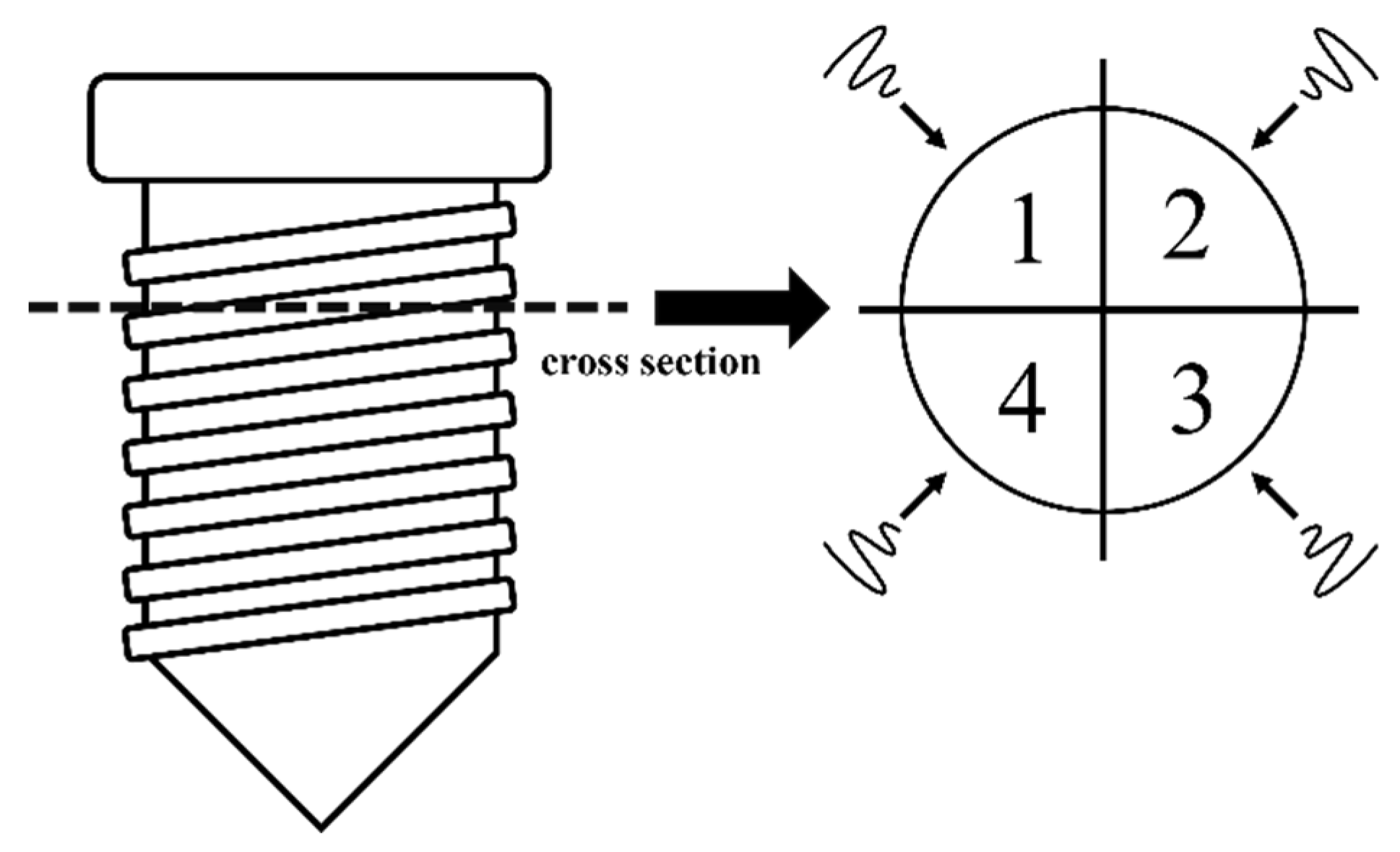
2.2. Laser System
2.3. Experiment 1: Morphologic Changes of the Microstructured Fixture Surface of Titanium Implants Following Irradiation (Non-IP Group)
2.4. Experiment 2: Morphologic Changes of the Microstructure Fixture Surface of Titanium Implants Following Implantoplasty Plus Irradiation (IP Group)
2.5. Morphologic Analysis
2.6. Compositional Analysis
2.7. Surface Roughness Analysis
2.8. Statistical Analysis
3. Results
3.1. Morphologic Analysis of Stereomicroscopy and SEM
3.2. Compositional Analysis of EDS
3.3. Surface Roughness
4. Discussion
5. Conclusions
Author Contributions
Funding
Institutional Review Board Statement
Informed Consent Statement
Data Availability Statement
Acknowledgments
Conflicts of Interest
References
- Moraschini, V.; Poubel, L.A.; Ferreira, V.F.; Barboza Edos, S. Evaluation of survival and success rates of dental implants reported in longitudinal studies with a follow-up period of at least 10 years: A systematic review. Int. J. Oral Maxillofac. Surg. 2015, 44, 377–388. [Google Scholar] [CrossRef] [PubMed]
- Adell, R.; Lekholm, U.; Rockler, B.; Branemark, P.I. A 15-year study of osseointegrated implants in the treatment of the edentulous jaw. Int. J. Oral Surg. 1981, 10, 387–416. [Google Scholar] [CrossRef] [PubMed]
- Berglundh, T.; Armitage, G.; Araujo, M.G.; Avila-Ortiz, G.; Blanco, J.; Camargo, P.M.; Chen, S.; Cochran, D.; Derks, J.; Figuero, E.; et al. Peri-implant diseases and conditions: Consensus report of workgroup 4 of the 2017 World Workshop on the Classification of Periodontal and Peri-Implant Diseases and Conditions. J. Clin. Periodontol. 2018, 45, S286–S291. [Google Scholar] [CrossRef] [PubMed]
- Sakka, S.; Baroudi, K.; Nassani, M.Z. Factors associated with early and late failure of dental implants. J. Investig. Clin. Dent. 2012, 3, 258–261. [Google Scholar] [CrossRef]
- Schwarz, F.; Derks, J.; Monje, A.; Wang, H.L. Peri-implantitis. J. Periodontol. 2018, 89 (Suppl. 1), S267–S290. [Google Scholar] [CrossRef]
- Lindhe, J.; Meyle, J.; Group D of European Workshop on Periodontology. Peri-implant diseases: Consensus report of the sixth European workshop on periodontology. J. Clin. Periodontol. 2008, 35, 282–285. [Google Scholar]
- Rosen, P.; Clem, D.; Cochran, D.; Froum, S.; McAllister, B.; Renvert, S.; Wang, H.L. Peri-implant mucositis and peri-implantitis: A current understanding of their diagnoses and clinical implications. J. Periodontol. 2013, 84, 436–443. [Google Scholar]
- Derks, J.; Tomasi, C. Peri-implant health and disease. A systematic review of current epidemiology. J. Clin. Periodontol. 2015, 42 (Suppl. 16), S158–S171. [Google Scholar] [CrossRef]
- Klinge, B.; Meyle, J.; Working Group 2. Peri-implant tissue destruction. The third EAO consensus conference 2012. Clin. Oral Implant. Res. 2012, 23, 108–110. [Google Scholar]
- Patel, A. Non-surgical management of peri-implant diseases. Prim. Dent. J. 2014, 3, 62–65. [Google Scholar] [CrossRef]
- Matsuyama, T.; Aoki, A.; Oda, S.; Yoneyama, T.; Ishikawa, I. Effects of the Er:YAG laser irradiation on titanium implant materials and contaminated implant abutment surfaces. J. Clin. Laser Med. Surg. 2003, 21, 7–17. [Google Scholar] [CrossRef] [PubMed]
- Taniguchi, Y.; Aoki, A.; Mizutani, K.; Takeuchi, Y.; Ichinose, S.; Takasaki, A.A.; Schwarz, F.; Izumi, Y. Optimal Er:YAG laser irradiation parameters for debridement of microstructured fixture surfaces of titanium dental implants. Lasers Med. Sci. 2013, 28, 1057–1068. [Google Scholar] [CrossRef] [PubMed]
- Kreisler, M.; Kohnen, W.; Marinello, C.; Gotz, H.; Duschner, H.; Jansen, B.; d’Hoedt, B. Bactericidal effect of the Er:YAG laser on dental implant surfaces: An in vitro study. J. Periodontol. 2002, 73, 1292–1298. [Google Scholar] [CrossRef] [PubMed]
- Alagl, A.S.; Madi, M.; Bedi, S.; Al Onaizan, F.; Al-Aql, Z.S. The Effect of Er,Cr:YSGG and Diode Laser Applications on Dental Implant Surfaces Contaminated with Acinetobacter Baumannii and Pseudomonas Aeruginosa. Materials 2019, 12, 2073. [Google Scholar] [CrossRef]
- Aoki, A.; Ando, Y.; Watanabe, H.; Ishikawa, I. In vitro studies on laser scaling of subgingival calculus with an erbium:YAG laser. J. Periodontol. 1994, 65, 1097–1106. [Google Scholar] [CrossRef]
- Scarano, A.; Lorusso, F.; Inchingolo, F.; Postiglione, F.; Petrini, M. The Effects of Erbium-Doped Yttrium Aluminum Garnet Laser (Er: YAG) Irradiation on Sandblasted and Acid-Etched (SLA) Titanium, an In Vitro Study. Materials 2020, 13, 4174. [Google Scholar] [CrossRef]
- Schwarz, F.; Aoki, A.; Becker, J.; Sculean, A. Laser application in non-surgical periodontal therapy: A systematic review. J. Clin. Periodontol. 2008, 35, 29–44. [Google Scholar] [CrossRef]
- Aoki, A.; Mizutani, K.; Schwarz, F.; Sculean, A.; Yukna, R.A.; Takasaki, A.A.; Romanos, G.E.; Taniguchi, Y.; Sasaki, K.M.; Zeredo, J.L.; et al. Periodontal and peri-implant wound healing following laser therapy. Periodontology 2000 2015, 68, 217–269. [Google Scholar] [CrossRef]
- Takagi, T.; Aoki, A.; Ichinose, S.; Taniguchi, Y.; Tachikawa, N.; Shinoki, T.; Meinzer, W.; Sculean, A.; Izumi, Y. Effective removal of calcified deposits on microstructured titanium fixture surfaces of dental implants with erbium lasers. J. Periodontol. 2018, 89, 680–690. [Google Scholar] [CrossRef]
- Miller, R.J. Treatment of the contaminated implant surface using the Er,Cr:YSGG laser. Implant Dent. 2004, 13, 165–170. [Google Scholar] [CrossRef]
- Chegeni, E.; Espana-Tost, A.; Figueiredo, R.; Valmaseda-Castellon, E.; Arnabat-Dominguez, J. Effect of an Er,Cr:YSGG Laser on the Surface of Implants: A Descriptive Comparative Study of 3 Different Tips and Pulse Energies. Dent. J. 2020, 8, 109. [Google Scholar] [CrossRef] [PubMed]
- Schwarz, F.; Sahm, N.; Iglhaut, G.; Becker, J. Impact of the method of surface debridement and decontamination on the clinical outcome following combined surgical therapy of peri-implantitis: A randomized controlled clinical study. J. Clin. Periodontol. 2011, 38, 276–284. [Google Scholar] [CrossRef] [PubMed]
- Schwarz, F.; Sahm, N.; Schwarz, K.; Becker, J. Impact of defect configuration on the clinical outcome following surgical regenerative therapy of peri-implantitis. J. Clin. Periodontol. 2010, 37, 449–455. [Google Scholar] [CrossRef] [PubMed]
- Romeo, E.; Ghisolfi, M.; Murgolo, N.; Chiapasco, M.; Lops, D.; Vogel, G. Therapy of peri-implantitis with resective surgery. A 3-year clinical trial on rough screw-shaped oral implants. Part I: Clinical outcome. Clin. Oral Implants Res. 2005, 16, 9–18. [Google Scholar] [CrossRef] [PubMed]
- Schwarz, F.; John, G.; Becker, J. The influence of implantoplasty on the diameter, chemical surface composition, and biocompatibility of titanium implants. Clin. Oral Investig. 2017, 21, 2355–2361. [Google Scholar] [CrossRef] [PubMed]
- Esposito, M.; Lausmaa, J.; Hirsch, J.M.; Thomsen, P. Surface analysis of failed oral titanium implants. J. Biomed. Mater. Res. 1999, 48, 559–568. [Google Scholar] [CrossRef]
- Strever, J.M.; Lee, J.; Ealick, W.; Peacock, M.; Shelby, D.; Susin, C.; Mettenberg, D.; El-Awady, A.; Rueggeberg, F.; Cutler, C.W. Erbium, Chromium:Yttrium-Scandium-Gallium-Garnet Laser Effectively Ablates Single-Species Biofilms on Titanium Disks Without Detectable Surface Damage. J. Periodontol. 2017, 88, 484–492. [Google Scholar] [CrossRef]
- Eldeniz, A.U.; Ozer, F.; Hadimli, H.H.; Erganis, O. Bactericidal efficacy of Er,Cr:YSGG laser irradiation against Enterococcus faecalis compared with NaOCl irrigation: An ex vivo pilot study. Int. Endod. J. 2007, 40, 112–119. [Google Scholar] [CrossRef]
- Rimondini, L.; Cicognani Simoncini, F.; Carrassi, A. Micro-morphometric assessment of titanium plasma-sprayed coating removal using burs for the treatment of peri-implant disease. Clin. Oral Implants Res. 2000, 11, 129–138. [Google Scholar] [CrossRef]
- Ramel, C.F.; Lussi, A.; Ozcan, M.; Jung, R.E.; Hammerle, C.H.; Thoma, D.S. Surface roughness of dental implants and treatment time using six different implantoplasty procedures. Clin. Oral Implants Res. 2016, 27, 776–781. [Google Scholar] [CrossRef]
- de Souza Junior, J.M.; Oliveira de Souza, J.G.; Pereira Neto, A.L.; Iaculli, F.; Piattelli, A.; Bianchini, M.A. Analysis of Effectiveness of Different Rotational Instruments in Implantoplasty: An In Vitro Study. Implant Dent. 2016, 25, 341–347. [Google Scholar] [CrossRef] [PubMed]
- Bollen, C.M.; Papaioanno, W.; Van Eldere, J.; Schepers, E.; Quirynen, M.; van Steenberghe, D. The influence of abutment surface roughness on plaque accumulation and peri-implant mucositis. Clin. Oral Implants Res. 1996, 7, 201–211. [Google Scholar] [CrossRef] [PubMed]
- Quirynen, M.; Bollen, C.M.; Papaioannou, W.; Van Eldere, J.; van Steenberghe, D. The influence of titanium abutment surface roughness on plaque accumulation and gingivitis: Short-term observations. Int. J. Oral Maxillofac. Implants 1996, 11, 169–178. [Google Scholar] [PubMed]
- Meier, R.M.; Pfammatter, C.; Zitzmann, N.U.; Filippi, A.; Kuhl, S. Surface quality after implantoplasty. Schweiz. Monatsschr. Zahnmed. 2012, 122, 714–724. [Google Scholar]
- Tawse-Smith, A.; Kota, A.; Jayaweera, Y.; Vuuren, W.J.; Ma, S. The effect of standardised implantoplasty protocol on titanium surface roughness: An in-vitro study. Braz. Oral Res. 2016, 30, e137. [Google Scholar] [CrossRef]
- Costa-Berenguer, X.; Garcia-Garcia, M.; Sanchez-Torres, A.; Sanz-Alonso, M.; Figueiredo, R.; Valmaseda-Castellon, E. Effect of implantoplasty on fracture resistance and surface roughness of standard diameter dental implants. Clin. Oral Implants Res. 2018, 29, 46–54. [Google Scholar] [CrossRef]
- Stavropoulos, A.; Bertl, K.; Eren, S.; Gotfredsen, K. Mechanical and biological complications after implantoplasty-A systematic review. Clin. Oral Implants Res. 2019, 30, 833–848. [Google Scholar] [CrossRef]
- Camps-Font, O.; Gonzalez-Barnadas, A.; Mir-Mari, J.; Figueiredo, R.; Gay-Escoda, C.; Valmaseda-Castellon, E. Fracture resistance after implantoplasty in three implant-abutment connection designs. Med. Oral Patol. Oral Cir. Bucal. 2020, 25, e691–e699. [Google Scholar] [CrossRef]


| C | O | P | Ti | |
|---|---|---|---|---|
| Control | 2.94 | 35.32 | 7.82 | 53.92 |
| 0.5 W | 2.40 | 33.21 | 7.15 | 57.25 * |
| 1 W | 2.96 | 29.49 * | 5.63 * | 61.93 * |
| 1.5 W | 2.54 | 30.05 * | 5.37 * | 62.04 * |
| 2 W | 3.05 | 22.74 * | 2.13 * | 72.08 * |
| C | O | P | Ti | |
|---|---|---|---|---|
| IP Control | 3.63 | 3.63 | 0.10 | 92.64 |
| IP + 0.5 W | 3.39 | 1.09 | 0.00 | 95.53 |
| IP + 1 W | 2.87 | 1.61 | 0.00 | 95.52 |
| IP + 1.5 W | 2.66 | 3.42 | 0.00 | 93.92 |
| IP + 2 W | 2.34 | 2.62 | 0.00 | 95.04 |
| Ra Value (Mean ± SD) | 95% CI | ||
|---|---|---|---|
| Control | 1.194 ± 0.06 | 1.165 | 1.165 |
| 0.5 W | 1.244 ± 0.091 | 1.181 | 1.181 |
| 1 W | 1.617 ± 0.237 | 1.453 | 1.453 |
| 1.5 W | 1.652 ± 0.383 | 1.386 | 1.386 |
| 2 W | 2.277 ± 0.309 * | 2.063 | 2.063 |
| Ra Value (Mean ± SD) | 95% CI | ||
|---|---|---|---|
| IP Control | 0.621 ± 0.06 | 0.579 | 0.663 |
| IP + 0.5 W | 0.709 ± 0.091 | 0.646 | 0.772 |
| IP + 1 W | 0.674 ± 0.157 | 0.565 | 0.783 |
| IP + 1.5 W | 0.728 ± 0.267 | 0.544 | 0.913 |
| IP + 2 W | 0.771 ± 0.134 | 0.679 | 0.864 |
Publisher’s Note: MDPI stays neutral with regard to jurisdictional claims in published maps and institutional affiliations. |
© 2022 by the authors. Licensee MDPI, Basel, Switzerland. This article is an open access article distributed under the terms and conditions of the Creative Commons Attribution (CC BY) license (https://creativecommons.org/licenses/by/4.0/).
Share and Cite
Lin, C.-J.; Tsai, M.-H.; Wu, Y.-L.; Lung, H.; Chen, H.-S.; Wu, A.Y.-J. The Effect of an Er, Cr: YSGG Laser Combined with Implantoplasty Treatment on Implant Surface Roughness and Morphologic Analysis: A Pilot In Vitro Study. J. Funct. Biomater. 2022, 13, 133. https://doi.org/10.3390/jfb13030133
Lin C-J, Tsai M-H, Wu Y-L, Lung H, Chen H-S, Wu AY-J. The Effect of an Er, Cr: YSGG Laser Combined with Implantoplasty Treatment on Implant Surface Roughness and Morphologic Analysis: A Pilot In Vitro Study. Journal of Functional Biomaterials. 2022; 13(3):133. https://doi.org/10.3390/jfb13030133
Chicago/Turabian StyleLin, Chih-Jen, Ming-Hsu Tsai, Yu-Ling Wu, Hsuan Lung, Hung-Shyong Chen, and Aaron Yu-Jen Wu. 2022. "The Effect of an Er, Cr: YSGG Laser Combined with Implantoplasty Treatment on Implant Surface Roughness and Morphologic Analysis: A Pilot In Vitro Study" Journal of Functional Biomaterials 13, no. 3: 133. https://doi.org/10.3390/jfb13030133