

Porous Biocoatings Based on Diatomite with Incorporated ZrO2 Particles for Biodegradable Magnesium Implants

 , and
, and
Abstract
:1. Introduction
2. Materials and Methods
- Anodic potentiostatic mode;
- 50 Hz pulse frequency;
- 100 µs pulse duration;
- 350–500 V voltage range (50 V step);
- 5 min deposition duration.
3. Results
3.1. Coating Thickness and Roughness
3.2. SEM
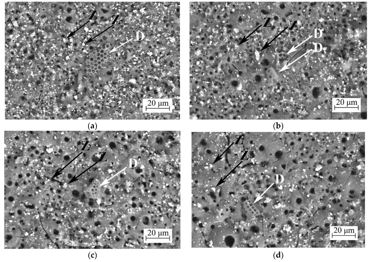
3.2.1. Coating Surface Morphology
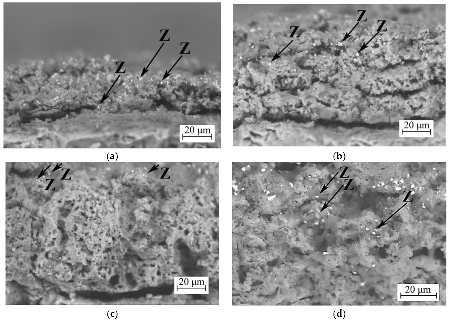
3.2.2. Coatings Cross-Sections
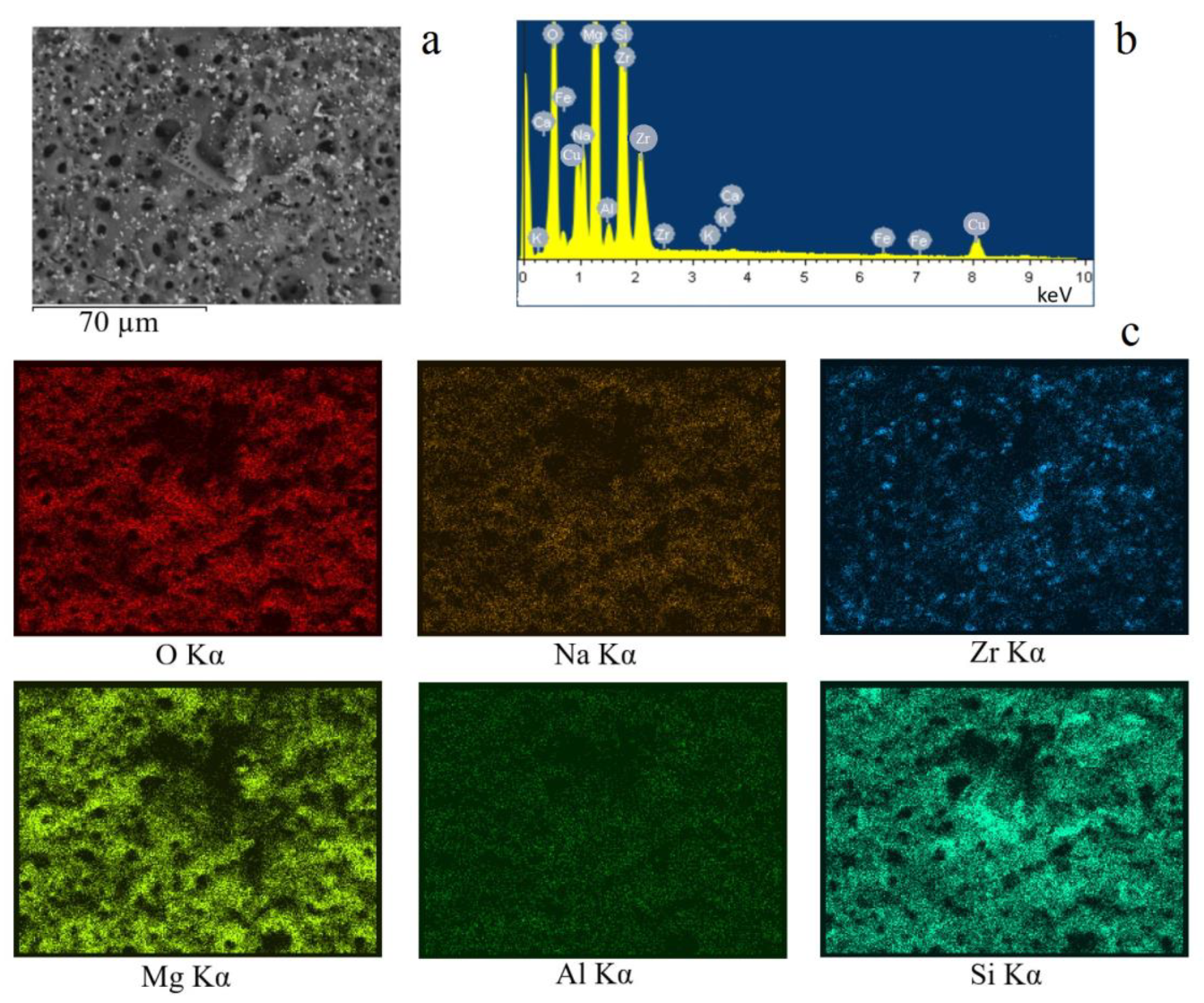
3.3. EDX Results
3.3.1. Coatings Surface
3.3.2. Coatings Cross-Sections
3.4. X-ray Results
3.5. Mechanical Properties
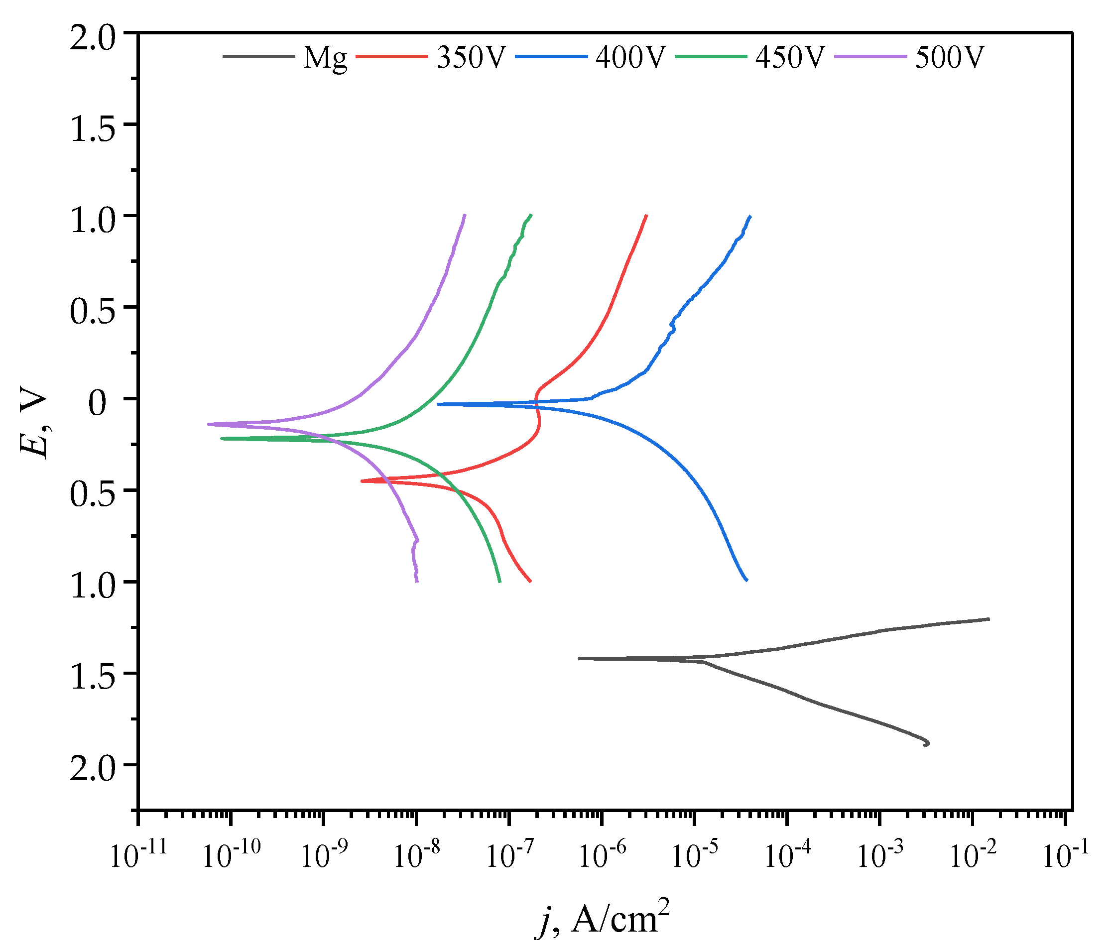
3.6. Electrochemical Properties
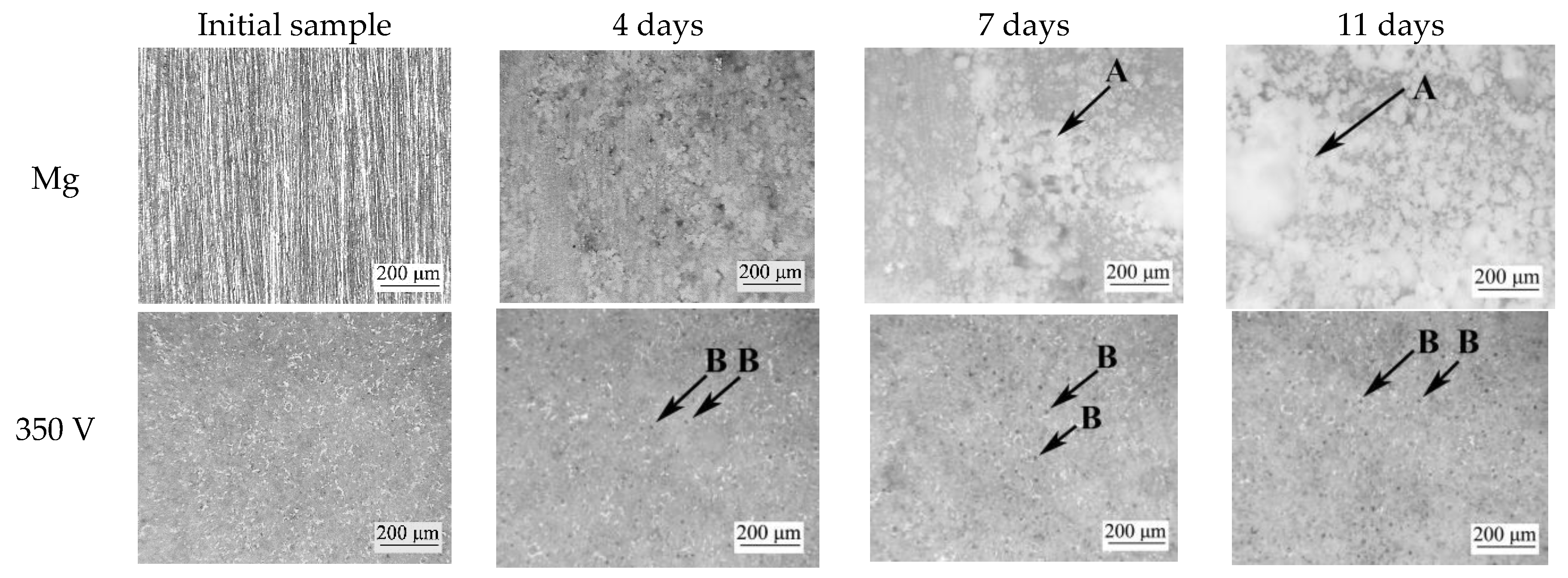
3.7. Bioresorption Process
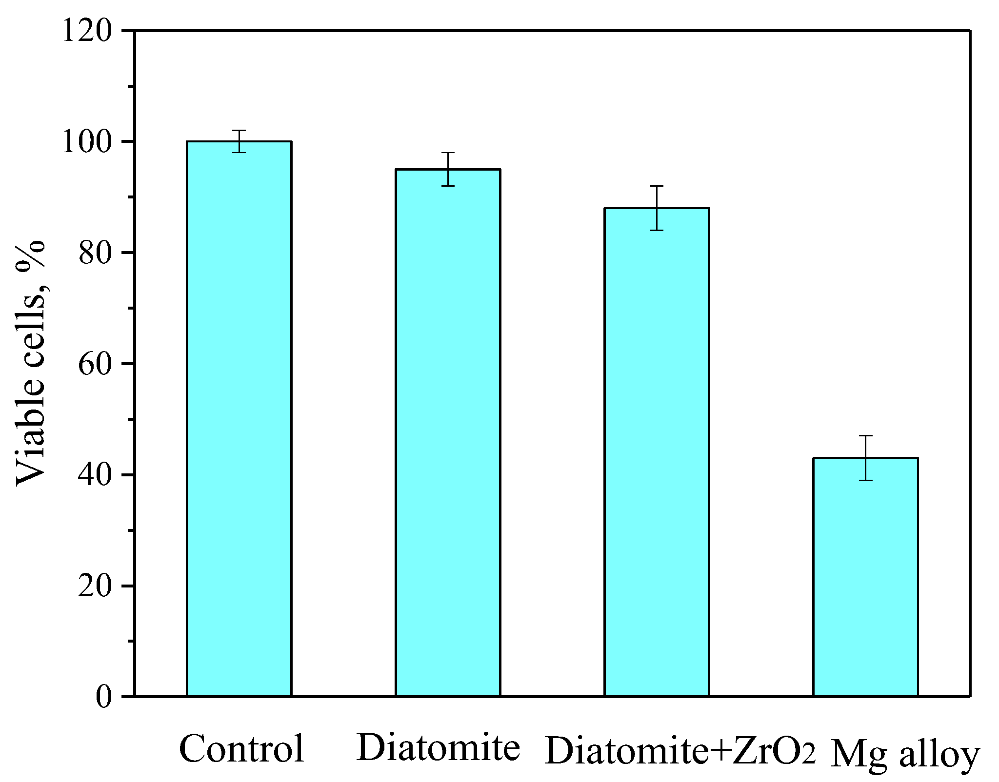
3.8. In Vitro Cytotoxic Assay
4. Discussion
5. Conclusions
Author Contributions
Funding
Data Availability Statement
Acknowledgments
Conflicts of Interest
References
- Schmidt, A.H. Autologous bone graft: Is it still the gold standard? Injury 2021, 52, 18–22. [Google Scholar] [CrossRef]
- Wang, J.; Yin, Q.; Gu, S.; Wu, Y.; Rui, Y. Induced membrane technique in the treatment of infectious bone defect: A clinical analysis. Orthop. Traumatol. Surg. Res. 2019, 105, 535–539. [Google Scholar] [CrossRef]
- Li, Y.; Pan, Q.; Xu, J.; He, X.; Li, H.A.; Oldridge, D.A.; Li, G.; Qin, L. Overview of methods for enhancing bone regeneration in distraction osteogenesis: Potential roles of biometals. J. Orthop. Transl. 2021, 27, 110–118. [Google Scholar] [CrossRef]
- Roddy, E.; DeBaun, M.R.; Daoud-Gray, A.; Yang, Y.P.; Gardner, M.J. Treatment of critical-sized bone defects: Clinical and tissue engineering perspectives. Eur. J. Orthop. Surg. Traumatol. 2018, 28, 351–362. [Google Scholar] [CrossRef]
- Verboket, R.; Leiblein, M.; Seebach, C.; Nau, C.; Janko, M.; Bellen, M.; Bönig, H.; Henrich, D.; Marzi, I. Autologous cell-based therapy for treatment of large bone defects: From bench to bedside. Eur. J. Trauma Emerg. Surg. 2018, 44, 649–665. [Google Scholar] [CrossRef]
- Xiong, Y.; Xiong, Y. Applications of bone regeneration hydrogels in the treatment of bone defects: A review. J. Mater. Sci. 2022, 57, 887–913. [Google Scholar] [CrossRef]
- Yanagihara, K.; Uchida, S.; Ohba, S.; Kataoka, K.; Itaka, K. Treatment of Bone Defects by Transplantation of Genetically Modified Mesenchymal Stem Cell Spheroids. Mol. Ther. Methods Clin. Dev. 2018, 9, 358–366. [Google Scholar] [CrossRef] [PubMed]
- Perez, J.R.; Kouroupis, D.; Li, D.J.; Best, T.M.; Kaplan, L.; Correa, D. Tissue Engineering and Cell-Based Therapies for Fractures and Bone Defects. Front. Bioeng. Biotechnol. 2018, 6, 105. [Google Scholar] [CrossRef] [PubMed]
- Pandey, A.; Awasthi, A.; Saxena, K.K. Metallic implants with properties and latest production techniques: A review. Adv. Mater. Process. Technol. 2020, 6, 405–440. [Google Scholar] [CrossRef]
- Morsada, Z.; Hossain, M.M.; Islam, M.T.; Mobin, M.A.; Saha, S. Recent progress in biodegradable and bioresorbable materials: From passive implants to active electronics. Appl. Mater. Today 2021, 25, 101257. [Google Scholar] [CrossRef]
- Shuai, C.; Li, S.; Peng, S.; Feng, P.; Lai, Y.; Gao, C. Biodegradable metallic bone implants. Mater. Chem. Front. 2019, 3, 544–562. [Google Scholar] [CrossRef]
- Prasad, K.; Bazaka, O.; Chua, M.; Rochford, M.; Fedrick, L.; Spoor, J.; Symes, R.; Tieppo, M.; Collins, C.; Cao, A.; et al. Metallic Biomaterials: Current Challenges and Opportunities. Materials 2017, 10, 884. [Google Scholar] [CrossRef] [PubMed]
- Ibrahim, M.Z.; Sarhan, A.A.D.; Yusuf, F.; Hamdi, M. Biomedical materials and techniques to improve the tribological, mechanical and biomedical properties of orthopedic implants—A review article. J. Alloy. Compd. 2017, 714, 636–667. [Google Scholar] [CrossRef]
- Kaur, M.; Singh, K. Review on titanium and titanium based alloys as biomaterials for orthopaedic applications. Mater. Sci. Eng. C 2019, 102, 844–862. [Google Scholar] [CrossRef]
- Sedelnikova, M.B.; Sharkeev, Y.P.; Tolkacheva, T.V.; Uvarkin, P.V.; Chebodaeva, V.V.; Prosolov, K.A.; Bakina, O.V.; Kashin, A.D.; Shcheglova, N.A.; Panchenko, A.A.; et al. Additively manufactured porous titanium 3D–scaffolds with antibacterial Zn-, Ag- calcium phosphate biocoatings. Mater. Charact. 2022, 186, 111782. [Google Scholar] [CrossRef]
- Li, J.; Cui, X.; Hooper, G.J.; Lim, K.S.; Woodfield, T.B.F. Rational design, bio-functionalization and biological performance of hybrid additive manufactured titanium implants for orthopaedic applications: A review. J. Mech. Behav. Biomed. Mater. 2020, 105, 103671. [Google Scholar] [CrossRef]
- Zhang, E.; Zhao, X.; Hu, J.; Wang, R.; Fu, S.; Qin, G. Antibacterial metals and alloys for potential biomedical implants. Bioact. Mater. 2021, 6, 2569–2612. [Google Scholar] [CrossRef]
- Chacón, J.M.; Núñez, P.J.; Caminero, M.A.; García-Plaza, E.; Vallejo, J.; Blanco, M. 3D printing of patient-specific 316L–stainless–steel medical implants using fused filament fabrication technology: Two veterinary case studies. Bio-Des. Manuf. 2022, 5, 808–815. [Google Scholar] [CrossRef]
- Savvidis, M.; Papavasiliou, K.; Taitzoglou, I.; Giannakopoulou, A.; Kitridis, D.; Galanis, N.; Vrabas, I.; Tsiridis, E. Postoperative Administration of Alpha-tocopherol Enhances Osseointegration of Stainless Steel Implants: An In Vivo Rat Model. Clin. Orthop. Relat. Res. 2020, 478, 406–419. [Google Scholar] [CrossRef]
- Rodriguez-Contreras, A.; Punset, M.; Calero, J.A.; Gil, F.J.; Ruperez, E.; Manero, J.M. Powder metallurgy with space holder for porous titanium implants: A review. J. Mater. Sci. Technol. 2021, 76, 129–149. [Google Scholar] [CrossRef]
- Kusano, T.; Seki, T.; Higuchi, Y.; Takegami, Y.; Osawa, Y.; Ishiguro, N. Preoperative Canal Bone Ratio is Related to High-Degree Stress Shielding: A Minimum 5-Year Follow-Up Study of a Proximally Hydroxyapatite-Coated Straight Tapered Titanium Femoral Component. J. Arthroplast. 2018, 33, 1764–1769. [Google Scholar] [CrossRef] [PubMed]
- Prakasam, M.; Locs, J.; Salma-Ancane, K.; Loca, D.; Largeteau, A.; Berzina-Cimdina, L. Biodegradable Materials and Metallic Implants—A Review. J. Funct. Biomater. 2017, 8, 44. [Google Scholar] [CrossRef] [PubMed]
- Han, H.-S.; Loffredo, S.; Jun, I.; Edwards, J.; Kim, Y.-C.; Seok, H.-K.; Witte, F.; Mantovani, D.; Glyn-Jones, S. Current status and outlook on the clinical translation of biodegradable metals. Mater. Today 2019, 23, 57–71. [Google Scholar] [CrossRef]
- Li, C.; Guo, C.; Fitzpatrick, V.; Ibrahim, A.; Zwierstra, M.J.; Hanna, P.; Lechtig, A.; Nazarian, A.; Lin, S.J.; Kaplan, D.L. Design of biodegradable, implantable devices towards clinical translation. Nat. Rev. Mater. 2020, 5, 61–81. [Google Scholar] [CrossRef]
- Hussain, M.; Khan, S.M.; Al-Khaled, K.; Ayadi, M.; Abbas, N.; Chammam, W. Performance analysis of biodegradable materials for orthopedic applications. Mater. Today Commun. 2022, 31, 103167. [Google Scholar] [CrossRef]
- Song, R.; Murphy, M.; Li, C.; Ting, K.; Soo, C.; Zheng, Z. Current development of biodegradable polymeric materials for biomedical applications. Drug Des. Dev. Ther. 2018, 12, 3117–3145. [Google Scholar] [CrossRef]
- Alizadeh-Osgouei, M.; Li, Y.; Wen, C. A comprehensive review of biodegradable synthetic polymer-ceramic composites and their manufacture for biomedical applications. Bioact. Mater. 2019, 4, 22–36. [Google Scholar] [CrossRef]
- Chakraborty Banerjee, P.; Al-Saadi, S.; Choudhary, L.; Harandi, S.E.; Singh, R. Magnesium Implants: Prospects and Challenges. Materials 2019, 12, 136. [Google Scholar] [CrossRef]
- Zhao, D.; Brown, A.; Wang, T.; Yoshizawa, S.; Sfeir, C.; Heineman, W.R. In vivo quantification of hydrogen gas concentration in bone marrow surrounding magnesium fracture fixation hardware using an electrochemical hydrogen gas sensor. Acta Biomater. 2018, 73, 559–566. [Google Scholar] [CrossRef]
- Zhao, D.; Wu, J.; Chou, D.-T.; Hoagland, W.; Benson, D.; Dong, Z.; Kumta, P.N.; Heineman, W.R. Visual Hydrogen Mapping Sensor for Noninvasive Monitoring of Bioresorbable Magnesium Implants In Vivo. JOM 2020, 72, 1851–1858. [Google Scholar] [CrossRef]
- Chen, J.; Tan, L.; Yu, X.; Etim, I.P.; Ibrahim, M.; Yang, K. Mechanical properties of magnesium alloys for medical application: A review. J. Mech. Behav. Biomed. Mater. 2018, 87, 68–79. [Google Scholar] [CrossRef] [PubMed]
- Kashin, A.D.; Sedelnikova, M.B.; Chebodaeva, V.V.; Uvarkin, P.V.; Luginin, N.A.; Dvilis, E.S.; Kazmina, O.V.; Sharkeev, Y.P.; Khlusov, I.A.; Miller, A.A.; et al. Diatomite-based ceramic biocoating for magnesium implants. Ceram. Int. 2022, 48, 28059–28071. [Google Scholar] [CrossRef]
- Sedelnikova, M.B.; Ugodchikova, A.V.; Tolkacheva, T.V.; Chebodaeva, V.V.; Cluklhov, I.A.; Khimich, M.A.; Bakina, O.V.; Lerner, M.I.; Egorkin, V.S.; Schmidt, J.; et al. Surface Modification of Mg0.8Ca Alloy via Wollastonite Micro-Arc Coatings: Significant Improvement in Corrosion Resistance. Metals 2021, 11, 754. [Google Scholar] [CrossRef]
- Simchen, F.; Sieber, M.; Kopp, A.; Lampke, T. Introduction to Plasma Electrolytic Oxidation—An Overview of the Process and Applications. Coatings 2020, 10, 628. [Google Scholar] [CrossRef]
- Clyne, T.W.; Troughton, S.C. A review of recent work on discharge characteristics during plasma electrolytic oxidation of various metals. Int. Mater. Rev. 2019, 64, 127–162. [Google Scholar] [CrossRef]
- Chaharmahali, R.; Fattah-alhosseini, A.; Babaei, K. Surface characterization and corrosion behavior of calcium phosphate (Ca-P) base composite layer on Mg and its alloys using plasma electrolytic oxidation (PEO): A review. J. Magnes. Alloy. 2021, 9, 21–40. [Google Scholar] [CrossRef]
- Han, J.; Tang, S.; San, H.; Sun, X.; Hu, J.; Yu, Y. Formation mechanism of calcium phosphate coating on a plasma electrolytic oxidized magnesium and its corrosion behavior in simulated body fluids. J. Alloy. Compd. 2020, 818, 152834. [Google Scholar] [CrossRef]
- Molaei, M.; Fattah-alhosseini, A.; Nouri, M.; Nourian, A. Systematic optimization of corrosion, bioactivity, and biocompatibility behaviors of calcium-phosphate plasma electrolytic oxidation (PEO) coatings on titanium substrates. Ceram. Int. 2022, 48, 6322–6337. [Google Scholar] [CrossRef]
- Sedelnikova, M.; Bakina, O.; Ugodchikova, A.; Tolkacheva, T.; Khimich, M.; Uvarkin, P.; Kashin, A.; Miller, A.; Egorkin, V.; Schmidt, J.; et al. The Role of Microparticles of β-TCP and Wollastonite in the Creation of Biocoatings on Mg0.8Ca Alloy. Metals 2022, 12, 1647. [Google Scholar] [CrossRef]
- Kazek-Kęsik, A.; Leśniak, K.; Zhidkov, I.S.; Korotin, D.M.; Kukharenko, A.I.; Cholakh, S.O.; Kalemba-Rec, I.; Suchanek, K.; Kurmaev, E.Z.; Simka, W. Influence of Alkali Treatment on Anodized Titanium Alloys in Wollastonite Suspension. Metals 2017, 7, 322. [Google Scholar] [CrossRef]
- Adeleke, S.A.; Ramesh, S.; Bushroa, A.R.; Ching, Y.C.; Sopyan, I.; Maleque, M.A.; Krishnasamy, S.; Chandran, H.; Misran, H.; Sutharsini, U. The properties of hydroxyapatite ceramic coatings produced by plasma electrolytic oxidation. Ceram. Int. 2018, 44, 1802–1811. [Google Scholar] [CrossRef]
- Chaharmahali, R.; Fattah-Alhosseini, A.; Esfahani, H. Increasing the in-vitro corrosion resistance of AZ31B-Mg alloy via coating with hydroxyapatite using plasma electrolytic oxidation. J. Asian Ceram. Soc. 2020, 8, 39–49. [Google Scholar] [CrossRef]
- Zhang, X.; Wu, Y.; Lv, Y.; Yu, Y.; Dong, Z. Formation mechanism, corrosion behaviour and biological property of hydroxyapatite/TiO2 coatings fabricated by plasma electrolytic oxidation. Surf. Coat. Technol. 2020, 386, 125483. [Google Scholar] [CrossRef]
- Kostelac, L.; Pezzato, L.; Settimi, A.G.; Franceschi, M.; Gennari, C.; Brunelli, K.; Rampazzo, C.; Dabalà, M. Investigation of hydroxyapatite (HAP) containing coating on grade 2 titanium alloy prepared by plasma electrolytic oxidation (PEO) at low voltage. Surf. Interfaces 2022, 30, 101888. [Google Scholar] [CrossRef]
- Molaei, M.; Nouri, M.; Babaei, K.; Fattah-Alhosseini, A. Improving surface features of PEO coatings on titanium and titanium alloys with zirconia particles: A review. Surf. Interfaces 2021, 22, 100888. [Google Scholar] [CrossRef]
- Muhaffel, F.; Kaba, M.; Cempura, G.; Derin, B.; Kruk, A.; Atar, E.; Cimenoglu, H. Influence of alumina and zirconia incorporations on the structure and wear resistance of titania-based MAO coatings. Surf. Coat. Technol. 2019, 377, 124900. [Google Scholar] [CrossRef]
- Muhaffel, F.; Baydogan, M.; Cimenoglu, H. A study to enhance the mechanical durability of the MAO coating fabricated on the 7075 Al alloy for wear-related high temperature applications. Surf. Coat. Technol. 2021, 409, 126843. [Google Scholar] [CrossRef]
- Lu, X.; Chen, Y.; Blawert, C.; Li, Y.; Zhang, T.; Wang, F.; Kainer, K.U.; Zheludkevich, M. Influence of SiO2 Particles on the Corrosion and Wear Resistance of Plasma Electrolytic Oxidation-Coated AM50 Mg Alloy. Coatings 2018, 8, 306. [Google Scholar] [CrossRef]
- Nadimi, M.; Dehghanian, C.; Etemadmoghadam, A. Influence of SiO2 nanoparticles incorporating into ceramic coatings generated by PEO on Aluminium alloy: Morphology, adhesion, corrosion, and wear resistance. Mater. Today Commun. 2022, 31, 103587. [Google Scholar] [CrossRef]
- Krishtal, M.M.; Ivashin, P.V.; Polunin, A.V.; Borgardt, E.D. The effect of dispersity of silicon dioxide nanoparticles added to electrolyte on the composition and properties of oxide layers formed by plasma electrolytic oxidation on magnesium 9995A. Mater. Lett. 2019, 241, 119–122. [Google Scholar] [CrossRef]
- Mashtalyar, D.V.; Imshinetskiy, I.M.; Nadaraia, K.V.; Gnedenkov, A.S.; Sinebryukhov, S.L.; Ustinov, A.Y.; Samokhin, A.V.; Gnedenkov, S.V. Influence of ZrO2/SiO2 nanomaterial incorporation on the properties of PEO layers on Mg-Mn-Ce alloy. J. Magnes. Alloy. 2022, 10, 513–526. [Google Scholar] [CrossRef]
- Chaharmahali, R.; Fattah-alhosseini, A.; Nouri, M.; Babaei, K. Improving surface characteristics of PEO coatings of Mg and its alloys with zirconia nanoparticles: A review. Appl. Surf. Sci. Adv. 2021, 6, 100131. [Google Scholar] [CrossRef]
- Yao, W.; Wu, L.; Wang, J.; Jiang, B.; Zhang, D.; Serdechnova, M.; Shulha, T.; Blawert, C.; Zheludkevich, M.L.; Pan, F. Micro-arc oxidation of magnesium alloys: A review. J. Mater. Sci. Technol. 2022, 118, 158–180. [Google Scholar] [CrossRef]
- Wang, Z.; Cheng, Z.; Zhang, Y.; Shi, X.; Rao, M.; Wu, S. Effect of Voltage on the Microstructure and High-Temperature Oxidation Resistance of Micro-Arc Oxidation Coatings on AlTiCrVZr Refractory High-Entropy Alloy. Coatings 2023, 13, 14. [Google Scholar] [CrossRef]
- Wang, D.; Liu, X.; Wang, Y.; Zhang, Q.; Li, D.; Liu, X.; Su, H.; Zhang, Y.; Yu, S.; Shen, D. Role of the electrolyte composition in establishing plasma discharges and coating growth process during a micro-arc oxidation. Surf. Coat. Technol. 2020, 402, 126349. [Google Scholar] [CrossRef]
- Song, K.; Fan, J.; Li, W.; Jiang, J.; Xu, Z.; Zhang, C. Effect of ZrO2 types on ZrSiO4 formation. Ceram. Int. 2019, 45, 23444–23450. [Google Scholar] [CrossRef]
- Sedelnikova, M.B.; Ivanov, K.V.; Ugodchikova, A.V.; Kashin, A.D.; Uvarkin, P.V.; Sharkeev, Y.P.; Tolkacheva, T.V.; Tolmachev, A.I.; Schmidt, J.; Egorkin, V.S.; et al. The effect of pulsed electron irradiation on the structure, phase composition, adhesion and corrosion properties of calcium phosphate coating on Mg0.8Ca alloy. Mater. Chem. Phys. 2023, 294, 126996. [Google Scholar] [CrossRef]
- Mortazavi, G.; Jiang, J.; Meletis, E.I. Investigation of the plasma electrolytic oxidation mechanism of titanium. Appl. Surf. Sci. 2019, 488, 370–382. [Google Scholar] [CrossRef]
- Polunin, A.V.; Cheretaeva, A.O.; Borgardt, E.D.; Rastegaev, I.A.; Krishtal, M.M.; Katsman, A.V.; Yasnikov, I.S. Improvement of oxide layers formed by plasma electrolytic oxidation on cast Al–Si alloy by incorporating TiC nanoparticles. Surf. Coat. Technol. 2021, 423, 127603. [Google Scholar] [CrossRef]
- Zhuang, J.J.; Guo, Y.Q.; Xiang, N.; Xiong, Y.; Hu, Q.; Song, R.G. A study on microstructure and corrosion resistance of ZrO2-containingPEO coatings formed on AZ31 Mg alloy in phosphate-based electrolyte. Appl. Surf. Sci. 2015, 357, 1463–1471. [Google Scholar] [CrossRef]
- Lee, K.M.; Lee, B.U.; Yoon, S.I.; Lee, E.S.; Yoo, B.; Shin, D.H. Evaluation of plasma temperature during plasma oxidation processing of AZ91 Mg alloy through analysis of the melting behavior of incorporated particles. Electrochim. Acta 2012, 67, 6–11. [Google Scholar] [CrossRef]
- Lu, X.; Sah, S.P.; Scharnagl, N.; Störmer, M.; Starykevich, M.; Mohedano, M.; Blawert, C.; Zheludkevich, M.L.; Kainer, K.U. Degradation behavior of PEO coating on AM50 magnesium alloy produced from electrolytes with clay particle addition. Surf. Coat. Technol. 2015, 269, 155–169. [Google Scholar] [CrossRef]
- Chen, Y.-W.; Moussi, J.; Drury, J.L.; Wataha, J.C. Zirconia in biomedical applications. Expert Rev. Med. Devices 2016, 13, 945–963. [Google Scholar] [CrossRef] [PubMed]
- Magnani, G.; Fabbri, P.; Leoni, E.; Salernitano, E.; Mazzanti, F. New Perspectives on Zirconia Composites as Biomaterials. J. Compos. Sci. 2021, 5, 244. [Google Scholar] [CrossRef]


| Element | 350 V | 400 V | 450 V | 500 V |
|---|---|---|---|---|
| O Kα | 65.2 ± 0.9 | 63.9 ± 0.8 | 63.4 ± 1.3 | 63.8 ± 1.1 |
| Na Kα | 2.0 ± 0.3 | 2.5 ± 0.4 | 2.5 ± 0.5 | 2.8 ± 0.8 |
| Mg Kα | 15.3 ± 0.8 | 15.6 ± 0.7 | 16.7 ± 0.5 | 16.2 ± 0.9 |
| Al Kα | 0.7 ± 0.1 | 0.8 ± 0.2 | 0.8 ± 0.2 | 0.8 ± 0.4 |
| Si Kα | 12.3 ± 0.5 | 13.9 ± 0.9 | 13.5 ± 0.9 | 13.4 ± 0.5 |
| Ca Kα | 0.2 ± 0.1 | 0.1 ± 0.09 | 0.0 | 0.1 ± 0.08 |
| Fe Kα | 0.1 ± 0.03 | 0.2 ± 0.07 | 0.2 ± 0.1 | 0.2 ± 0.08 |
| Zr Kα | 4.2 ± 0.2 | 3.0 ± 0.1 | 2.9 ± 0.3 | 2.7 ± 0.2 |
| Element | 350 V | 400 V | 450 V | 500 V |
|---|---|---|---|---|
| O Kα | 64.0 ± 0.8 | 56.5 ± 1.1 | 56.2 ± 0.9 | 58.9 ± 1.1 |
| Na Kα | 1.8 ± 0.3 | 4.6 ± 0.6 | 4.1 ± 0.8 | 2.1 ± 0.3 |
| Mg Kα | 23.3 ± 0.3 | 32.5 ± 0.5 | 33.2 ± 0.5 | 32.0 ± 0.8 |
| Al Kα | 1.2 ± 0.2 | 1.2 ± 0.3 | 1.3 ± 0.5 | 1.5 ± 0.5 |
| Si Kα | 7.2 ± 0.3 | 4.5 ± 0.3 | 4.7 ± 0.3 | 4.6 ± 0.2 |
| Ca Kα | 0.2 ± 0.1 | 0.2 ± 0.1 | 0.1 ± 0.02 | 0.2 ± 0.1 |
| Zr Kα | 2.3 ± 0.2 | 0.5 ± 0.1 | 0.4 ± 0.1 | 0.7 ± 0.1 |
| Deposition Voltage, V | Critical Load, N | Optical Microphotography |
|---|---|---|
| 350 | 8.6 ± 0.5 | 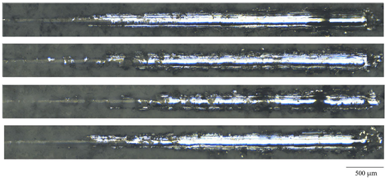 |
| 400 | 11.0 ± 0.6 | |
| 450 | 14.8 ± 0.8 | |
| 500 | 8.4 ± 0.7 |
| Sample | Ec, V | Jc, A cm−2 | Rp, Ω cm2 |
|---|---|---|---|
| Mg | −1.42 | 1.05 × 10⁻⁵ | 1.7 × 10³ |
| 350 V | −0.45 | 1.21 × 10⁻⁸ | 1.43 × 10⁶ |
| 400 V | −0.03 | 7.48 × 10⁻⁷ | 0.9 × 10⁴ |
| 450 V | −0.22 | 1.28 × 10⁻⁹ | 1.1 × 10⁷ |
| 500 V | −0.14 | 2.35 × 10⁻¹⁰ | 6.34 × 10⁷ |
Disclaimer/Publisher’s Note: The statements, opinions and data contained in all publications are solely those of the individual author(s) and contributor(s) and not of MDPI and/or the editor(s). MDPI and/or the editor(s) disclaim responsibility for any injury to people or property resulting from any ideas, methods, instructions or products referred to in the content. |
© 2023 by the authors. Licensee MDPI, Basel, Switzerland. This article is an open access article distributed under the terms and conditions of the Creative Commons Attribution (CC BY) license (https://creativecommons.org/licenses/by/4.0/).
Share and Cite
Sedelnikova, M.B.; Kashin, A.D.; Uvarkin, P.V.; Tolmachev, A.I.; Sharkeev, Y.P.; Ugodchikova, A.V.; Luginin, N.A.; Bakina, O.V. Porous Biocoatings Based on Diatomite with Incorporated ZrO2 Particles for Biodegradable Magnesium Implants. J. Funct. Biomater. 2023, 14, 241. https://doi.org/10.3390/jfb14050241
Sedelnikova MB, Kashin AD, Uvarkin PV, Tolmachev AI, Sharkeev YP, Ugodchikova AV, Luginin NA, Bakina OV. Porous Biocoatings Based on Diatomite with Incorporated ZrO2 Particles for Biodegradable Magnesium Implants. Journal of Functional Biomaterials. 2023; 14(5):241. https://doi.org/10.3390/jfb14050241
Chicago/Turabian StyleSedelnikova, Mariya B., Alexander D. Kashin, Pavel V. Uvarkin, Alexey I. Tolmachev, Yurii P. Sharkeev, Anna V. Ugodchikova, Nikita A. Luginin, and Olga V. Bakina. 2023. "Porous Biocoatings Based on Diatomite with Incorporated ZrO2 Particles for Biodegradable Magnesium Implants" Journal of Functional Biomaterials 14, no. 5: 241. https://doi.org/10.3390/jfb14050241