
Fabrication of a Triple-Layer Bionic Vascular Scaffold via Hybrid Electrospinning


Abstract
1. Introduction
2. Materials and Methods
2.1. Materials
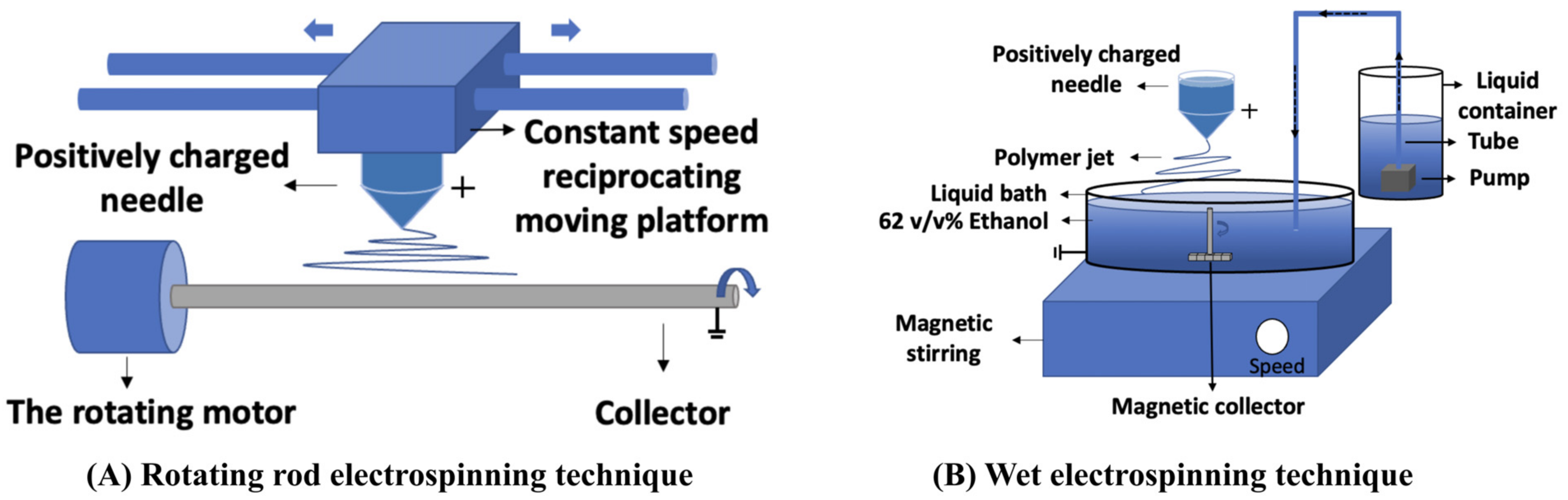
2.2. Set-Up
2.2.1. Wet Vertical Magnetic Rod Electrospinning (WVMRE)
2.2.2. Scaffold Fabrication
2.2.3. Morphology
2.2.4. FTIR
2.2.5. Water Contact Angle
2.2.6. Tensile Test
2.2.7. Material Degradation
2.3. In Vitro Evaluation
2.3.1. Cell Culture and Seeding
2.3.2. Cell Morphology and Viability Tests
2.4. Statistical Analysis
3. Results
3.1. Technical Optimization
3.2. Characterization of Scaffold
3.2.1. Morphology
3.2.2. Scaffold Composition
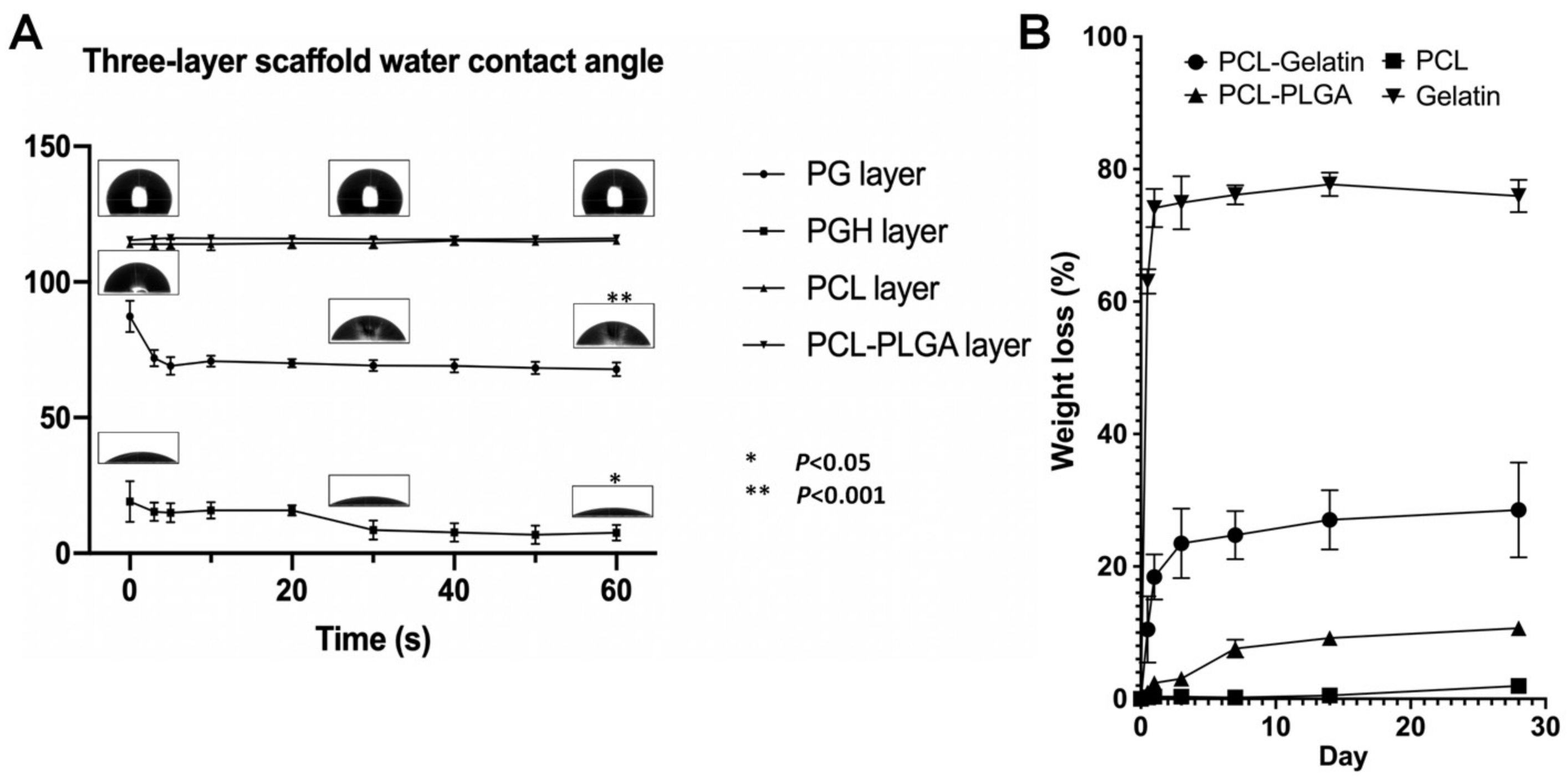
3.2.3. Water Contact Angle
3.2.4. Material Degradation
3.2.5. Mechanical Property Test
3.3. In Vitro Evaluation
Cell Morphology and Viability Tests
4. Discussion
5. Conclusions
Author Contributions
Funding
Institutional Review Board Statement
Informed Consent Statement
Data Availability Statement
Conflicts of Interest
References
- Frostegård, J. Immunity, atherosclerosis and cardiovascular disease. BMC Med. 2013, 11, 117. [Google Scholar] [CrossRef] [PubMed]
- Wang, J.-N.; Kan, C.-D.; Lin, S.-H.; Chang, K.-C.; Tsao, S.; Wong, T.-W. Potential of Autologous Progenitor Cells and Decellularized Porcine Artery Matrix in Construction of Tissue-engineered Vascular Grafts. Organogenesis 2021, 17, 72–84. [Google Scholar] [CrossRef]
- Lawall, H.; Huppert, P.; Espinola-Klein, C.; Rümenapf, G. The diagnosis and treatment of peripheral arterial vascular disease. Dtsch. Arztebl. Int. 2016, 113, 729. [Google Scholar] [CrossRef] [PubMed]
- Simsa, R.; Vila, X.M.; Salzer, E.; Teuschl, A.; Jenndahl, L.; Bergh, N.; Fogelstrand, P. Effect of fluid dynamics on decellularization efficacy and mechanical properties of blood vessels. PLoS ONE 2019, 14, e0220743. [Google Scholar] [CrossRef] [PubMed]
- Hu, K.; Li, Y.; Ke, Z.; Yang, H.; Lu, C.; Li, Y.; Guo, Y.; Wang, W. History, progress and future challenges of artificial blood vessels: A narrative review. Biomater. Transl. 2022, 3, 81–98. [Google Scholar] [CrossRef]
- Mallis, P.; Kostakis, A.; Stavropoulos-Giokas, C.; Michalopoulos, E. Future perspectives in small-diameter vascular graft engineering. Bioengineering 2020, 7, 160. [Google Scholar] [CrossRef]
- Wang, Y. Research and Progress of implantable cardiovascular materials and devices. Engineering 2021, 7, 1707–1709. [Google Scholar] [CrossRef]
- Albrektsson, T.; Jemt, T.; Mölne, J.; Tengvall, P.; Wennerberg, A. On inflammation-immunological balance theory—A critical apprehension of disease concepts around implants: Mucositis and marginal bone loss may represent normal conditions and not necessarily a state of disease. Clin. Implant Dent. Relat. Res. 2019, 21, 183–189. [Google Scholar] [CrossRef]
- Vashaghian, M.; Zaat, S.J.; Smit, T.H.; Roovers, J.P. Biomimetic implants for pelvic floor repair. Neurourol. Urodyn. 2018, 37, 566–580. [Google Scholar] [CrossRef]
- Nilawar, S.; Uddin, M.; Chatterjee, K. Surface engineering of biodegradable implants: Emerging trends in bioactive ceramic coatings and mechanical treatments. Mater. Adv. 2021, 2, 7820–7841. [Google Scholar] [CrossRef]
- Hiob, M.A.; She, S.; Muiznieks, L.D.; Weiss, A.S. Biomaterials and modifications in the development of small-diameter vascular grafts. ACS Biomater. Sci. Eng. 2017, 3, 712–723. [Google Scholar] [CrossRef] [PubMed]
- Leal, B.B.; Wakabayashi, N.; Oyama, K.; Kamiya, H.; Braghirolli, D.I.; Pranke, P. Vascular tissue engineering: Polymers and methodologies for small caliber vascular grafts. Front. Cardiovasc. Med. 2021, 7, 592361. [Google Scholar] [CrossRef] [PubMed]
- Seifu, D.G.; Purnama, A.; Mequanint, K.; Mantovani, D. Small-diameter vascular tissue engineering. Nat. Rev. Cardiol. 2013, 10, 410–421. [Google Scholar] [CrossRef]
- Zhang, X.; Zhang, Y. Tissue engineering applications of three-dimensional bioprinting. Cell Biochem. Biophys. 2015, 72, 777–782. [Google Scholar] [CrossRef] [PubMed]
- Helms, F.; Aper, T.; Lau, S.; Haverich, A.; Wilhelmi, M.; Böer, U. Generation of a Physiological Three-Layered Bioartificial Blood Vessel by Mechanical Stimulation. Thorac. Cardiovasc. Surg. 2021, 69, S1–S85. [Google Scholar] [CrossRef]
- Yalcin Enis, I.; Gok Sadikoglu, T. Design parameters for electrospun biodegradable vascular grafts. J. Ind. Text. 2016, 47, 2205–2227. [Google Scholar] [CrossRef]
- Ercolani, E.; Del Gaudio, C.; Bianco, A. Vascular tissue engineering of small-diameter blood vessels: Reviewing the electrospinning approach. J. Tissue Eng. Regen. Med. 2015, 9, 861–888. [Google Scholar] [CrossRef]
- Li, M.-X.; Li, L.; Zhou, S.-Y.; Cao, J.-H.; Liang, W.-H.; Tian, Y.; Shi, X.-T.; Yang, X.-B.; Wu, D.-Y. A biomimetic orthogonal-bilayer tubular scaffold for the co-culture of endothelial cells and smooth muscle cells. RSC Adv. 2021, 11, 31783–31790. [Google Scholar] [CrossRef]
- Tinajero, M.G.; Gotlieb, A.I. Recent developments in vascular adventitial pathobiology: The dynamic adventitia as a complex regulator of vascular disease. Am. J. Pathol. 2020, 190, 520–534. [Google Scholar] [CrossRef]
- Keirouz, A.; Wang, Z.; Reddy, V.S.; Nagy, Z.K.; Vass, P.; Buzgo, M.; Ramakrishna, S.; Radacsi, N. The History of Electrospinning: Past, Present, and Future Developments. Adv. Mater. Technol. 2023, 8, 2201723. [Google Scholar] [CrossRef]
- Chen, J.; Yu, Z.; Li, C.; Lv, Y.; Hong, S.; Hu, P.; Liu, Y. Review of the principles, devices, parameters, and applications for centrifugal electrospinning. Macromol. Mater. Eng. 2022, 307, 2200057. [Google Scholar] [CrossRef]
- Zhuang, Y.; Fu, Y.; Huang, S.; Gong, S. The application of intelligent sensors in medical research: A review. Biomed. Eng. Commun. 2023, 2, 17. [Google Scholar] [CrossRef]
- Mi, H.-Y.; Jing, X.; Yu, E.; Wang, X.; Li, Q.; Turng, L.-S. Manipulating the structure and mechanical properties of thermoplastic polyurethane/polycaprolactone hybrid small diameter vascular scaffolds fabricated via electrospinning using an assembled rotating collector. J. Mech. Behav. Biomed. Mater. 2018, 78, 433–441. [Google Scholar] [CrossRef] [PubMed]
- Zhou, Q.; Wang, Y.; Chen, P.; Lv, J.; Wang, W. Effect of pole piece structure on magnetic lens electrospinning system: Experimental and simulation study. Colloids Surf. A Physicochem. Eng. Asp. 2023, 677, 132402. [Google Scholar] [CrossRef]
- Zheng, Y.; Miao, J.; Maeda, N.; Frey, D.; Linhardt, R.J.; Simmons, T.J. Uniform nanoparticle coating of cellulose fibers during wet electrospinning. J. Mater. Chem. A 2014, 2, 15029–15034. [Google Scholar] [CrossRef]
- Wang, H.; Kong, L.; Ziegler, G.R. Aligned wet-electrospun starch fiber mats. Food Hydrocoll. 2019, 90, 113–117. [Google Scholar] [CrossRef]
- Bölgen, N.; Menceloğlu, Y.Z.; Acatay, K.; Vargel, İ.; Pişkin, E. In vitro and in vivo degradation of non-woven materials made of poly (ε-caprolactone) nanofibers prepared by electrospinning under different conditions. J. Biomater. Sci. Polym. Ed. 2005, 16, 1537–1555. [Google Scholar] [CrossRef] [PubMed]
- Gaspar-Pintiliescu, A.; Stanciuc, A.-M.; Craciunescu, O. Natural composite dressings based on collagen, gelatin and plant bioactive compounds for wound healing: A review. Int. J. Biol. Macromol. 2019, 138, 854–865. [Google Scholar] [CrossRef] [PubMed]
- Su, K.; Wang, C. Recent advances in the use of gelatin in biomedical research. Biotechnol. Lett. 2015, 37, 2139–2145. [Google Scholar] [CrossRef]
- Wang, Z.; Sun, B.; Zhang, M.; Ou, L.; Che, Y.; Zhang, J.; Kong, D. Functionalization of electrospun poly(ε-caprolactone) scaffold with heparin and vascular endothelial growth factors for potential application as vascular grafts. J. Bioact. Compat. Polym. 2012, 28, 154–166. [Google Scholar] [CrossRef]
- Guo, W.; Yang, K.; Qin, X.; Luo, R.; Wang, H.; Huang, R. Polyhydroxyalkanoates in tissue repair and regeneration. Eng. Regen. 2022, 3, 24–40. [Google Scholar] [CrossRef]
- Aghdam, R.M.; Najarian, S.; Shakhesi, S.; Khanlari, S.; Shaabani, K.; Sharifi, S. Investigating the effect of PGA on physical and mechanical properties of electrospun PCL/PGA blend nanofibers. J. Appl. Polym. Sci. 2012, 124, 123–131. [Google Scholar] [CrossRef]
- Hanzly, L.E.; Kristofferson, K.A.; Chauhan, N.; Barone, J.R. Biologically controlled gelatin actuators. Green Mater. 2021, 9, 157–166. [Google Scholar] [CrossRef]
- Kemme, M.; Heinzel-Wieland, R. Quantitative assessment of antimicrobial activity of PLGA films loaded with 4-hexylresorcinol. J. Funct. Biomater. 2018, 9, 4. [Google Scholar] [CrossRef] [PubMed]
- Gautam, S.; Dinda, A.K.; Mishra, N.C. Fabrication and characterization of PCL/gelatin composite nanofibrous scaffold for tissue engineering applications by electrospinning method. Mater. Sci. Eng. C 2013, 33, 1228–1235. [Google Scholar] [CrossRef] [PubMed]
- De Wael, K.; Verstraete, A.; Van Vlierberghe, S.; Dejonghe, W.; Dubruel, P.; Adriaens, M. The electrochemistry of a gelatin modified gold electrode. Int. J. Electrochem. Sci. 2011, 6, 1810–1819. [Google Scholar] [CrossRef]
- Hiep, N.T.; Lee, B.-T. Electro-spinning of PLGA/PCL blends for tissue engineering and their biocompatibility. J. Mater. Sci. Mater. Med. 2010, 21, 1969–1978. [Google Scholar] [CrossRef] [PubMed]
- Singh, G.; Tanurajvir, K.; Ravinder, K.; Kaur, A. Recent biomedical applications and patents on biodegradable polymer-PLGA. Int. J. Pharmacol. Pharm. Sci. 2014, 1, 30–42. [Google Scholar]
- Yu, L.; Feng, Y.; Li, Q.; Hao, X.; Liu, W.; Zhou, W.; Shi, C.; Ren, X.; Zhang, W. PLGA/SF blend scaffolds modified with plasmid complexes for enhancing proliferation of endothelial cells. React. Funct. Polym. 2015, 91, 19–27. [Google Scholar] [CrossRef]
- Breuer, T.; Jimenez, M.; Humphrey, J.D.; Shinoka, T.; Breuer, C.K. Tissue engineering of vascular grafts: A case report from bench to bedside and back. Arterioscler. Thromb. Vasc. Biol. 2023, 43, 399–409. [Google Scholar] [CrossRef]
- Goins, A.; Webb, A.R.; Allen, J.B. Multi-layer approaches to scaffold-based small diameter vessel engineering: A review. Mater. Sci. Eng. C 2019, 97, 896–912. [Google Scholar] [CrossRef]
- Lopera Higuita, M.; Griffiths, L.G. Small diameter xenogeneic extracellular matrix scaffolds for vascular applications. Tissue Eng. Part B Rev. 2020, 26, 26–45. [Google Scholar] [CrossRef]
- Mejía Suaza, M.L.; Hurtado Henao, Y.; Moncada Acevedo, M.E. Wet Electrospinning and its Applications: A Review. TecnoLógicas 2022, 25, e2223. [Google Scholar] [CrossRef]
- Tong, H.-W.; Wang, M.; Lu, W.W. Electrospun Poly(Hydroxybutyrate-co-Hydroxyvalerate) Fibrous Membranes Consisting of Parallel-Aligned Fibers or Cross-Aligned Fibers: Characterization and Biological Evaluation. J. Biomater. Sci. Polym. Ed. 2011, 22, 2475–2497. [Google Scholar] [CrossRef] [PubMed]
- Lu, W.; Ma, M.; Xu, H.; Zhang, B.; Cao, X.; Guo, Y. Gelatin nanofibers prepared by spiral-electrospinning and cross-linked by vapor and liquid-phase glutaraldehyde. Mater. Lett. 2015, 140, 1–4. [Google Scholar] [CrossRef]
- Chen, H.; Wang, C.; Ali, I.; Li, H.; Chen, X.; Yang, W.; Han, W.; Liu, H.; Jiao, D.; Yin, F. Uniform Distribution and Densification of Jets in Needleless Electrospinning Using Annular Tip Nozzle. Polymers 2019, 11, 1301. [Google Scholar] [CrossRef] [PubMed]
- Norzain, N.A.; Yu, Z.-W.; Lin, W.-C.; Su, H.-H. Micropatterned fibrous scaffold produced by using template-assisted electrospinning technique for wound healing application. Polymers 2021, 13, 2821. [Google Scholar] [CrossRef]
- Li, Z.; Guo, J.; Guan, F.; Yin, J.; Yang, Q.; Zhang, S.; Tian, J.; Zhang, Y.; Ding, M.; Wang, W. Oxidized sodium alginate cross-linked calcium alginate/antarctic krill protein composite fiber for improving strength and water resistance. Colloids Surf. A Physicochem. Eng. Asp. 2023, 656, 130317. [Google Scholar] [CrossRef]
- Yang, Y.; Wang, C.; Wiener, C.G.; Hao, J.; Shatas, S.; Weiss, R.A.; Vogt, B.D. Tough Stretchable Physically-Cross-linked Electrospun Hydrogel Fiber Mats. ACS Appl. Mater. Interfaces 2016, 8, 22774–22779. [Google Scholar] [CrossRef]
- Okutan, N.; Terzi, P.; Altay, F. Affecting parameters on electrospinning process and characterization of electrospun gelatin nanofibers. Food Hydrocoll. 2014, 39, 19–26. [Google Scholar] [CrossRef]
- Hirsh, J.; Anand, S.S.; Halperin, J.L.; Fuster, V. Guide to anticoagulant therapy: Heparin: A statement for healthcare professionals from the American Heart Association. Circulation 2001, 103, 2994–3018. [Google Scholar] [CrossRef] [PubMed]
- Vlodavsky, I.; Ilan, N.; Nadir, Y.; Brenner, B.; Katz, B.-Z.; Naggi, A.; Torri, G.; Casu, B.; Sasisekharan, R. Heparanase, heparin and the coagulation system in cancer progression. Thromb. Res. 2007, 120, S112–S120. [Google Scholar] [CrossRef] [PubMed]


| Layers | Materials | Polymer Solution | Electrospinning Parameters | |||
|---|---|---|---|---|---|---|
| Polymer Solvent | Polymer Concentration (wt%) | Flow Rate (mL/h) | Distance (cm) | Voltage (kV) | ||
| Inner layer | PCL/Gelatin | HFIP | 24 (PCL:Gelatin = 1:1) | 0.4 | 15 | 13 |
| Middle layer | PCL | DMF/chloroform (2/8 v/v) | 13 | 1.5 | 12 | 13 |
| Outer layer | PCL-PLGA | DMF/chloroform (2/8 v/v) | 26 (PCL:PLGA = 75:25) | 0.4 | 15 | 13 |
| Porosity (%) | The Thickness of Each Layer (μm) | |
|---|---|---|
| PCL-Gelatin | 71.51 ±2.68 | 49.50 ± 13.66 |
| PCL | 78.44 ±1.25 | 158.67 ± 21.32 |
| PCL-PLGA | 76.14 ±1.45 | 63.50 ± 14.28 |
| Layer | Axial Young’s Modulus (MPa) | Radial Young’s Modulus (MPa) | Axial Maximum Tensile Strength (MPa) | Radial Maximum Tensile Strength (MPa) | Axial Elongation at Break (%) | Radial Elongation at Break (%) |
|---|---|---|---|---|---|---|
| PCL- Gelatin-Heparin | 26.76 ± 79.36 | 32.13 ± 143.02 | 4.08 ± 1.51 | 6.08 ± 1.96 * | 341.61 ± 92.01 | 383.70 ± 42.94 |
| PCL | 5.13 ± 10.02 | 62.09 ± 550.40 *** | 0.4 ± 0.02 | 4.26 ± 2.85 ** | 198.29 ± 106.80 | 156.28 ± 77.00 |
| PCL- PLGA | 16.28 ± 5.04 | 12.35 ± 5.75 * | 1.47 ± 0.008 | 0.95 ± 0.03 *** | 185.50 ± 23.70 | 49.16 ± 7.52 *** |
| Three- layer | 13.89 ± 13.01 | 10.67 ± 19.35 | 1.59 ± 0.14 | 2.97 ± 0.30 ** | 378.50 ± 122.20 | 454.20 ± 133.10 |
Disclaimer/Publisher’s Note: The statements, opinions and data contained in all publications are solely those of the individual author(s) and contributor(s) and not of MDPI and/or the editor(s). MDPI and/or the editor(s) disclaim responsibility for any injury to people or property resulting from any ideas, methods, instructions or products referred to in the content. |
© 2024 by the authors. Licensee MDPI, Basel, Switzerland. This article is an open access article distributed under the terms and conditions of the Creative Commons Attribution (CC BY) license (https://creativecommons.org/licenses/by/4.0/).
Share and Cite
Ma, F.; Huang, X.; Wang, Y. Fabrication of a Triple-Layer Bionic Vascular Scaffold via Hybrid Electrospinning. J. Funct. Biomater. 2024, 15, 140. https://doi.org/10.3390/jfb15060140
Ma F, Huang X, Wang Y. Fabrication of a Triple-Layer Bionic Vascular Scaffold via Hybrid Electrospinning. Journal of Functional Biomaterials. 2024; 15(6):140. https://doi.org/10.3390/jfb15060140
Chicago/Turabian StyleMa, Feier, Xiaojing Huang, and Yan Wang. 2024. "Fabrication of a Triple-Layer Bionic Vascular Scaffold via Hybrid Electrospinning" Journal of Functional Biomaterials 15, no. 6: 140. https://doi.org/10.3390/jfb15060140
APA StyleMa, F., Huang, X., & Wang, Y. (2024). Fabrication of a Triple-Layer Bionic Vascular Scaffold via Hybrid Electrospinning. Journal of Functional Biomaterials, 15(6), 140. https://doi.org/10.3390/jfb15060140