
Experimental Analysis of Stress Shielding Effects in Screw Spacers Placed in Porcine Spinal Tissue
 ,
,
Abstract
:1. Introduction
2. Materials and Methods
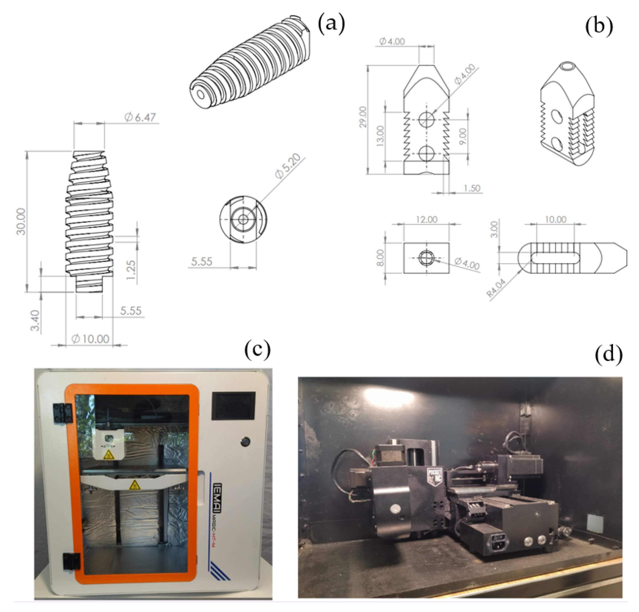
2.1. Device Description
2.2. Sample and Testing
2.3. Stress Shielding
3. Results
4. Discussion
5. Conclusions
Supplementary Materials
Author Contributions
Funding
Institutional Review Board Statement
Informed Consent Statement
Data Availability Statement
Acknowledgments
Conflicts of Interest
References
- Hernández-Ortega, M.F.; Torres-SanMiguel, C.R.; Alcántara-Arreola, E.A.; Paredes-Rojas, J.C.; Cabrera-Rodríguez, O.; Urriolagoitia-Calderón, G.M. Numerical Assessment of Interspinous Spacers for Lumbar Spine. Prosthesis 2023, 5, 939–951. [Google Scholar] [CrossRef]
- Meena, V.K.; Kalra, P.; Sinha, R.K. Finite element study on the influence of pore size and structure on stress shielding effect of additive manufactured spinal Cage. Comput. Methods Biomech. Biomed. Eng. 2022, 25, 566–577. [Google Scholar] [CrossRef]
- James, S.L.; Abate, D.; Abate, K.H.; Abay, S.M.; Abbafati, C.; Abbasi, N.; Abbastabar, H.; Abd-Allah, F.; Abdela, J.; Abdelalim, A.; et al. Global, regional, and national incidence, prevalence, and years lived with disability for 354 diseases and injuries for 195 countries and territories, 1990–2017: A systematic analysis for the Global Burden of Disease Study 2017. Lancet 2018, 392, 1789–1858. [Google Scholar] [CrossRef] [PubMed]
- Behennah, J.; Conway, R.; Fisher, J.; Osborne, N.; Steele, J. The relationship between balance performance, lumbar extension strength, trunk extension endurance, and pain in participants with chronic low back pain, and those without. Clin. Biomech. 2018, 53, 22–30. [Google Scholar] [CrossRef]
- Allegri, M.; Montella, S.; Salici, F.; Valente, A.; Marchesini, M.; Compagnone, C.; Baciarello, M.; Manferdini, M.E.; Fanelli, G. Mechanisms of low back pain: A guide for diagnosis and therapy. F1000Research 2016, 5, 1530. [Google Scholar] [CrossRef]
- Hernandez-Lucas, P.; Leirós-Rodríguez, R.; Lopez-Barreiro, J.; García-Soidán, J.L. Is the combination of exercise therapy and health education more effective than usual medical care in the prevention of non-specific back pain? A systematic review with meta-analysis. Ann. Med. 2022, 54, 3106–3115. [Google Scholar] [CrossRef] [PubMed]
- Jecko, V.; Loit, M.-P.; Houston, D.; Champeaux-Depond, C. Functional Outcome after Spinal Meningioma Surgery. Asian Spine J. 2022, 16, 692–701. [Google Scholar] [CrossRef]
- Shao, X.; Liu, H.; Wu, J.; Qian, Z.; Qu, R.; Liu, T. A retrospective comparative study of postoperative sagittal balance in isthmic L5–S1 spondylolisthesis using single segment or two-segment pedicle screw fixation. BMC Musculoskelet. Disord. 2022, 23, 145. [Google Scholar] [CrossRef]
- Ko, S.; Jun, C.; Nam, J. Comparison of Fusion Rate and Functional Outcome Between Local Cancellous Bone Plus Demineralized Bone Matrix and Local Bone in 1-Level Posterior Lumbar Interbody Fusion. Clin. Spine Surg. 2022, 35, E621–E626. [Google Scholar] [CrossRef]
- Tartara, F.; Bongetta, D.; Pilloni, G.; Colombo, E.V.; Giombelli, E. Custom-made trabecular titanium implants for the treatment of lumbar degenerative discopathy via ALIF/XLIF techniques: Rationale for use and preliminary results. Eur. Spine J. 2020, 29, 314–320. [Google Scholar] [CrossRef]
- Chan, A.Y.; Lien, B.V.; Choi, E.H.; Chan, A.K.; Hanna, G.; Lopez, A.M.; Brown, N.J.; Gattas, S.; Kirillova, L.; Horton, D.; et al. Back pain outcomes after minimally invasive anterior lumbar interbody fusion: A systematic review. Neurosurg. Focus 2020, 49, E3. [Google Scholar] [CrossRef]
- Huang, H.; Liu, J.; Wang, L.; Fan, Y. A critical review on the biomechanical study of cervical interbody fusion cage. Med. Nov. Technol. Devices 2021, 11, 100070. [Google Scholar] [CrossRef]
- Gorissen, B.M.C.; Wolschrijn, C.F.; van Vilsteren, A.A.M.; van Rietbergen, B.; van Weeren, P.R. Trabecular bone of precocials at birth; Are they prepared to run for the wolf(f)? J. Morphol. 2016, 277, 948–956. [Google Scholar] [CrossRef] [PubMed]
- Holmes, P.B.; Wolf, B.J.; Zhou, J. A CBCT atlas of buccal cortical bone thickness in interradicular spaces. Angle Orthod. 2015, 85, 911–919. [Google Scholar] [CrossRef]
- Shahzamanian, M.M.; Banerjee, R.; Dahotre, N.B.; Srinivasa, A.R.; Reddy, J.N. Analysis of stress shielding reduction in bone fracture fixation implant using functionally graded materials. Compos. Struct. 2023, 321, 117262. [Google Scholar] [CrossRef]
- Lee, H.-J.; Kim, B.-K.; Jung, S.-H.; Lee, Y.; Dan, J. Does stress shielding after radial head arthroplasty affect functional outcomes? Eur. J. Orthop. Surg. Traumatol. 2022, 33, 1591–1598. [Google Scholar] [CrossRef] [PubMed]
- Yan, Y.; Yu, J.; Wang, Y.; Dong, H.; Zhang, K.; Wang, Y.; Xue, Y.; Wu, X.; He, L.; Feng, H.; et al. A newly designed personalized interbody fusion cage and its biomechanical analysis. Acta Mech. Sin. 2023, 39, 623047. [Google Scholar] [CrossRef]
- Zhang, Q.-H.; Cossey, A.; Tong, J. Stress shielding in periprosthetic bone following a total knee replacement: Effects of implant material, design and alignment. Med. Eng. Phys. 2016, 38, 1481–1488. [Google Scholar] [CrossRef]
- Wang, L.; Chen, Q.; Yarlagadda, P.K.D.V.; Zhu, F.; Li, Q.; Li, Z. Single-parameter mechanical design of a 3D-printed octet truss topological scaffold to match natural cancellous bones. Mater. Des. 2021, 209, 109986. [Google Scholar] [CrossRef]
- Mirulla, A.I.; Muccioli, G.M.M.; Fratini, S.; Zaffagnini, S.; Ingrassia, T.; Bragonzoni, L.; Innocenti, B. Analysis of different geometrical features to achieve close-to-bone stiffness material properties in medical device: A feasibility numerical study. Comput. Methods Programs Biomed. 2022, 221, 106875. [Google Scholar] [CrossRef]
- Zhang, X.-Y.; Fang, G.; Xing, L.-L.; Liu, W.; Zhou, J. Effect of porosity variation strategy on the performance of functionally graded Ti-6Al-4V scaffolds for bone tissue engineering. Mater. Des. 2018, 157, 523–538. [Google Scholar] [CrossRef]
- Zhang, L.; Song, B.; Choi, S.-K.; Shi, Y. A topology strategy to reduce stress shielding of additively manufactured porous metallic biomaterials. Int. J. Mech. Sci. 2021, 197, 106331. [Google Scholar] [CrossRef]
- Martinez-Marquez, D.; Delmar, Y.; Sun, S.; Stewart, R.A. Exploring Macroporosity of Additively Manufactured Titanium Metamaterials for Bone Regeneration with Quality by Design: A Systematic Literature Review. Materials 2020, 13, 4794. [Google Scholar] [CrossRef]
- Tsuang, F.-Y.; Li, M.-J.; Chu, P.-H.; Tsou, N.-T.; Sun, J.-S. Mechanical performance of porous biomimetic intervertebral body fusion devices: An in vitro biomechanical study. J. Orthop. Surg. Res. 2023, 18, 71. [Google Scholar] [CrossRef]
- Makaram, H.; Swaminathan, R. Influence of pedicle screw thread width and recovery time after surgery on fixation strength. Curr. Dir. Biomed. Eng. 2021, 7, 751–754. [Google Scholar] [CrossRef]
- Safavi, S.; Yu, Y.; Robinson, D.L.; Gray, H.A.; Ackland, D.C.; Lee, P.V.S. Additively manufactured controlled porous orthopedic joint replacement designs to reduce bone stress shielding: A systematic review. J. Orthop. Surg. Res. 2023, 18, 42. [Google Scholar] [CrossRef]
- Ramirez, O.; Torres-San-Miguel, C.h.R.; Ceccarelli, M.; Urriolagoitia-Calderon, G. Experimental characterization of an osteosynthesis implant. In Advances in Mechanism and Machine Science, Proceedings of the 15th IFToMM World Congress on Mechanism and Machine Science, Krakow, Poland, 30 June–4 July 2019; Springer: Cham, Switzerland, 2019; pp. 53–62. [Google Scholar] [CrossRef]
- Magalhaes, K.; Barreira, L.M.S.; Fonseca, E.M.M.; Pereira, A.I. Cortical bone thickness and bone mass density in L2 vertebra, a comparison study with L3 and L4 measurements. Int. J. Med. Eng. Inf. 2015, 7, 156. [Google Scholar] [CrossRef]
- Lunney, J.K.; Van Goor, A.; Walker, K.E.; Hailstock, T.; Franklin, J.; Dai, C. Importance of the pig as a human biomedical model. Sci. Transl. Med. 2021, 13, eabd5758. [Google Scholar] [CrossRef]
- Cone, S.G.; Warren, P.B.; Fisher, M.B. Rise of the Pigs: Utilization of the Porcine Model to Study Musculoskeletal Biomechanics and Tissue Engineering During Skeletal Growth. Tissue Eng. Part C Methods 2017, 23, 763–780. [Google Scholar] [CrossRef]
- ASTM E9-19; Standard Test Methods of Compression Testing of Metallic Materials at Room Temperature. American Society for Testing and Materials: West Conshohocken, PA, USA, 2019.
- Hernández-Salazar, C.A.; Chamorro, C.E.; González-Estrada, O.A. Characterization of Pig Vertebrae under Axial Compression Integrating Radiomic Techniques and Finite Element Analysis. Inventions 2024, 9, 36. [Google Scholar] [CrossRef]
- Özkaya, N.; Leger, D.; Goldsheyder, D.; Nordin, M. Fundamentals of Biomechanics; Springer International Publishing: Cham, Switzerland, 2017. [Google Scholar] [CrossRef]
- Hamill, J.; Knutzen, K.M.; Derrick, T.R. Biomechanical Basis of Human Movement, 4th ed.; Wolters Kluwer: Alphen aan den Rijn, The Netherlands, 2015. [Google Scholar]
- Boresi, A.P.; Schmidt, R.J. Advanced Mechanics of Materials, 6th ed.; John Wiley & Sons: Hoboken, NJ, USA, 2003. [Google Scholar]
- Xu, D.S.; Walker, C.T.; Godzik, J.; Turner, J.D.; Smith, W.; Uribe, J.S. Minimally invasive anterior, lateral, and oblique lumbar interbody fusion: A literature review. Ann. Transl. Med. 2018, 6, 104. [Google Scholar] [CrossRef]
- Akbary, K.; Quillo-Olvera, J.; Lin, G.-X.; Jo, H.-J.; Kim, J.-S. Outcomes of Minimally Invasive Oblique Lumbar Interbody Fusion in Patients with Lumbar Degenerative Disease with Rheumatoid Arthritis. J. Neurol. Surg. A Cent. Eur. Neurosurg. 2019, 80, 162–168. [Google Scholar] [CrossRef] [PubMed]
- Huang, S.; Min, S.; Wang, S.; Jin, A. Biomechanical effects of an oblique lumbar interbody fusion combined with posterior augmentation: A finite element analysis. BMC Musculoskelet. Disord. 2022, 23, 611. [Google Scholar] [CrossRef]
- Wu, Y.; Ma, J.; Dai, J.; Wang, Y.; Bai, H.; Lu, B.; Chen, J.; Fan, X.; Ma, X. Design and Biomechanical Evaluation of a Bidirectional Expandable Cage for Oblique Lateral Interbody Fusion. World Neurosurg. 2023, 180, e644–e652. [Google Scholar] [CrossRef]
- Shen, H.; Fogel, G.R.; Zhu, J.; Liao, Z.; Liu, W. Biomechanical Analysis of Different Lumbar Interspinous Process Devices: A Finite Element Study. World Neurosurg. 2019, 127, e1112–e1119. [Google Scholar] [CrossRef]
- Al Zoubi, N.F.; Tarlochan, F.; Mehboob, H.; Jarrar, F. Design of Titanium Alloy Femoral Stem Cellular Structure for Stress Shielding and Stem Stability: Computational Analysis. Appl. Sci. 2022, 12, 1548. [Google Scholar] [CrossRef]
- Singh, S.K.; Tandon, P. Heterogeneous modeling based prosthesis design with porosity and material variation. J. Mech. Behav. Biomed. Mater. 2018, 87, 124–131. [Google Scholar] [CrossRef]
- Ou, K.; Liu, Q.; Liu, X.; Fu, Q.; Fan, J.; Sun, Y. Self-exothermic esterification-crosslinking of bio-polymer/graphene composite for application in interbody fusion cage. MRS Commun. 2022, 13, 8–15. [Google Scholar] [CrossRef]
- Chen, C.-S.; Shih, S.-L. Biomechanical analysis of a new lumbar interspinous device with optimized topology. Med. Biol. Eng. Comput. 2018, 56, 1333–1341. [Google Scholar] [CrossRef]
- Guo, L.-X.; Liu, J. Topology optimization and dynamic characteristic evaluation of W-shaped interspinous process device. Comput. Methods Biomech. Biomed. Eng. 2023, 26, 1610–1619. [Google Scholar] [CrossRef]
- Xiao, Z.; Wu, L.; Wu, W.; Tang, R.; Dai, J.; Zhu, D. Multi-Scale Topology Optimization of Femoral Stem Structure Subject to Stress Shielding Reduce. Materials 2023, 16, 3151. [Google Scholar] [CrossRef]
- Burchard, R.; Graw, J.A.; Soost, C.; Schmitt, J. Stress shielding effect after total hip arthroplasty varies between combinations of stem design and stiffness—A comparing biomechanical finite element analysis. Int. Orthop. 2023, 47, 1981–1987. [Google Scholar] [CrossRef]
- Ceddia, M.; Trentadue, B.; De Giosa, G.; Solarino, G. Topology Optimization of a Femoral Stem in Titanium and Carbon to Reduce Stress Shielding with the FEM Method. J. Compos. Sci. 2023, 7, 298. [Google Scholar] [CrossRef]


| Study Case | Velocity Displacement (mm/min) | Prosthesis | Stop Criterion |
|---|---|---|---|
| 1 | 2 | Metal intersomatic screw. | Until material fail |
| 2 | 2 | Metal intersomatic screw. | Load of 500 N |
| 3 | 2 | Metal intersomatic screw. | Load of 500 N |
| 4 | 1 | Metal cage. | Load of 500 N |
| 5 | 2 | None | Until material fail |
| 6 | 2 | Metal cage. | Load of 3000 N |
| 7 | 2 | Metal intersomatic screw. | Load of 3000 N |
| 8 | 2 | PEEK cage. | Until material fail |
| 9 | 2 | PEEK intersomatic screw. | Until material fail |
| 10 | 2 | PEEK intersomatic screw. | Until material fail |
| 11 | 2 | PEEK intersomatic screw. | Load of 3000 N |
| 12 | 2 | PEEK intersomatic screw. | Load of 500 N |
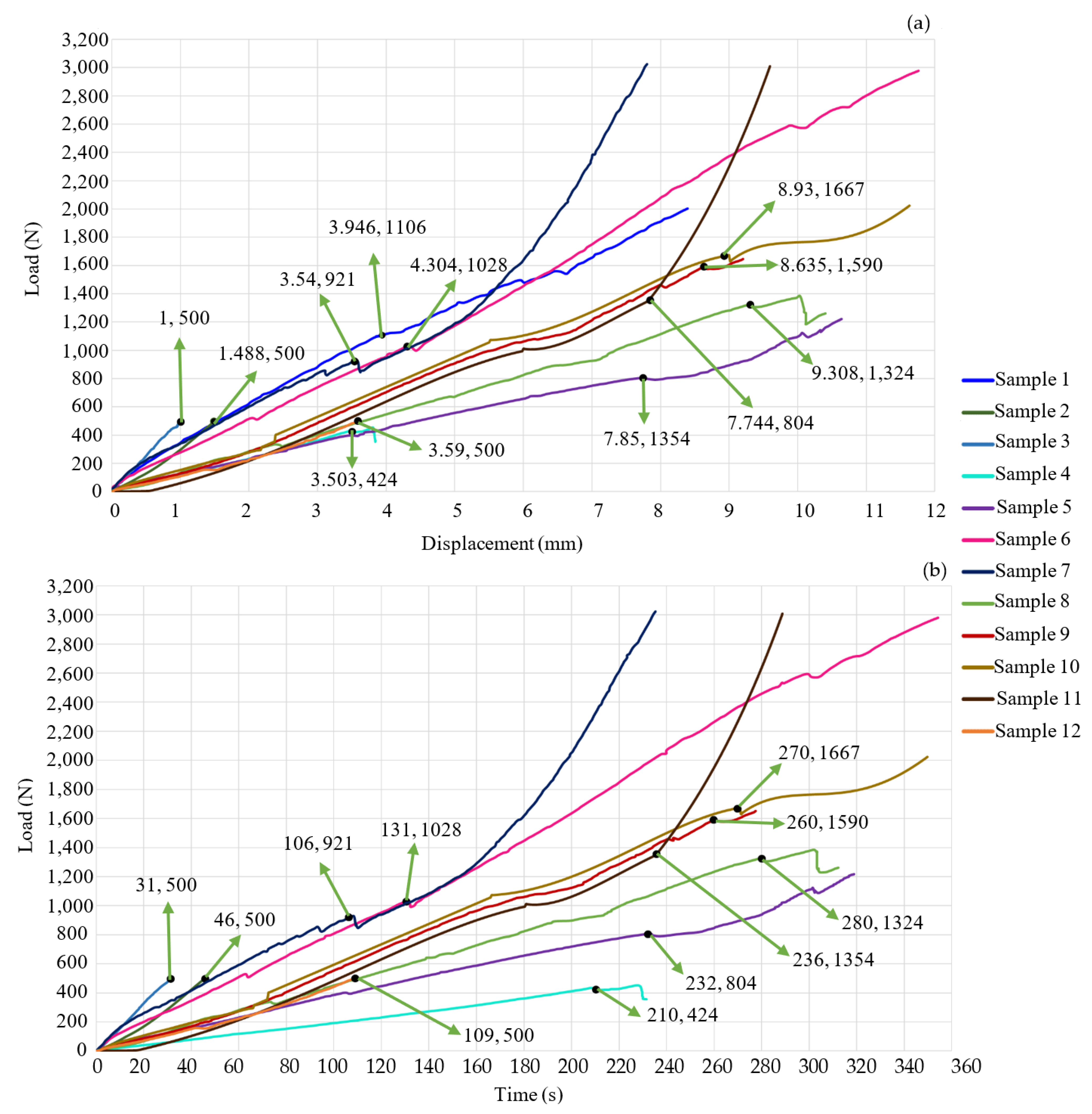
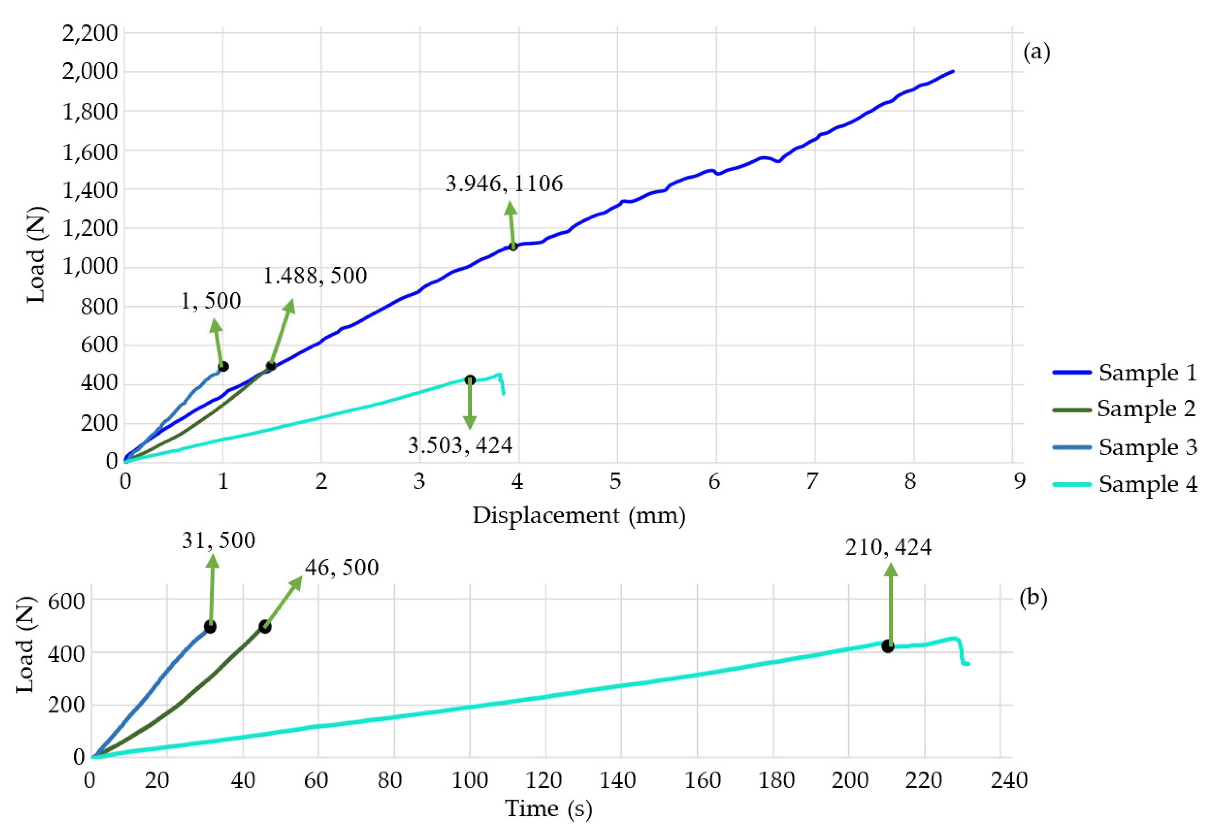
| Study Case | Critical Load (N) | Critical Displacement (mm) | Test’s Time (s) |
|---|---|---|---|
| 1 | 1106 | 3.946 | 252 |
| 2 | 500 | 1.488 | 46 |
| 3 | 500 | 2.488 | 31 |
| 4 | 424 | 3.503 | 231 |
| 5 | 804 | 7.744 | 234 |
| 6 | 1028 | 4.304 | 354 |
| 7 | 921 | 3.54 | 235 |
| 8 | 1324 | 9.308 | 312 |
| 9 | 1590 | 8.635 | 260 |
| 10 | 1667 | 8.93 | 349 |
| 11 | 1354 | 7.85 | 289 |
| 12 | 500 | 3.59 | 109 |
| Study Case | Critical Load (N) | SS (MPa) |
|---|---|---|
| 1 | 1106 | 80.2 |
| 2 | 500 | 53.92 |
| 3 | 500 | 76.26 |
| 4 | 424 | 71 |
| 6 | 1028 | 89.14 |
| 7 | 921 | 73.2 |
| 8 | 1324 | 36.93 |
| 9 | 1590 | 35.1 |
| 10 | 1667 | 35.93 |
| 11 | 1354 | 32.38 |
| 12 | 500 | 19.68 |
Disclaimer/Publisher’s Note: The statements, opinions and data contained in all publications are solely those of the individual author(s) and contributor(s) and not of MDPI and/or the editor(s). MDPI and/or the editor(s) disclaim responsibility for any injury to people or property resulting from any ideas, methods, instructions or products referred to in the content. |
© 2024 by the authors. Licensee MDPI, Basel, Switzerland. This article is an open access article distributed under the terms and conditions of the Creative Commons Attribution (CC BY) license (https://creativecommons.org/licenses/by/4.0/).
Share and Cite
Alcántara-Arreola, E.A.; Silva-Garcés, K.N.; Mendoza-Martínez, J.; Cardoso-Palomares, M.A.; Torres-SanMiguel, C.R. Experimental Analysis of Stress Shielding Effects in Screw Spacers Placed in Porcine Spinal Tissue. J. Funct. Biomater. 2024, 15, 238. https://doi.org/10.3390/jfb15080238
Alcántara-Arreola EA, Silva-Garcés KN, Mendoza-Martínez J, Cardoso-Palomares MA, Torres-SanMiguel CR. Experimental Analysis of Stress Shielding Effects in Screw Spacers Placed in Porcine Spinal Tissue. Journal of Functional Biomaterials. 2024; 15(8):238. https://doi.org/10.3390/jfb15080238
Chicago/Turabian StyleAlcántara-Arreola, Elliot Alonso, Karla Nayeli Silva-Garcés, Jocabed Mendoza-Martínez, Miguel Antonio Cardoso-Palomares, and Christopher René Torres-SanMiguel. 2024. "Experimental Analysis of Stress Shielding Effects in Screw Spacers Placed in Porcine Spinal Tissue" Journal of Functional Biomaterials 15, no. 8: 238. https://doi.org/10.3390/jfb15080238