
Boosting Performance of Self-Polarized Fully Printed Piezoelectric Nanogenerators via Modulated Strength of Hydrogen Bonding Interactions


Abstract
:
1. Introduction
2. Experimental Section
2.1. Materials
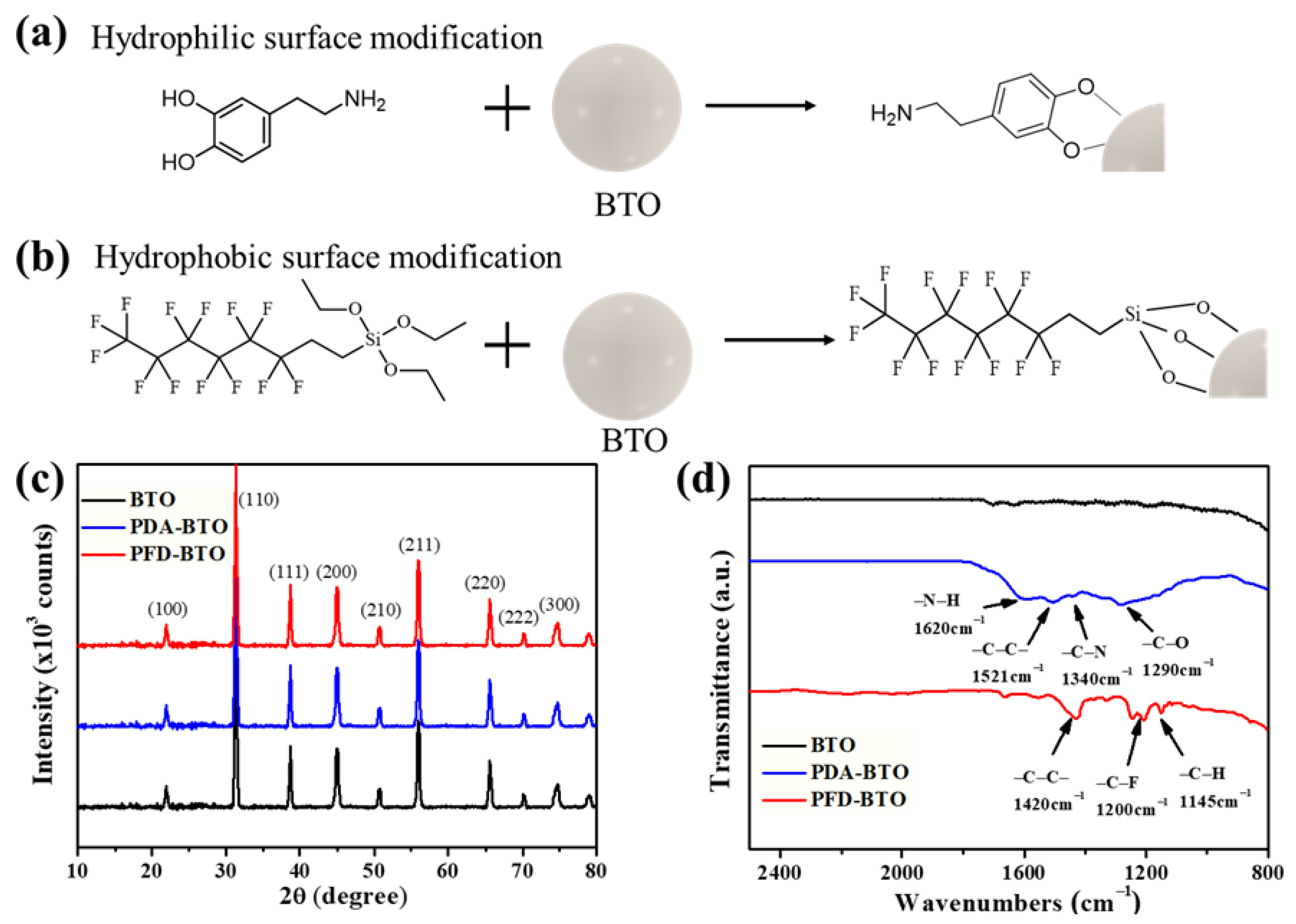
2.2. Preparation of PDA-BTO Nanoparticles
2.3. Preparation of PFD-BTO Nanoparticles
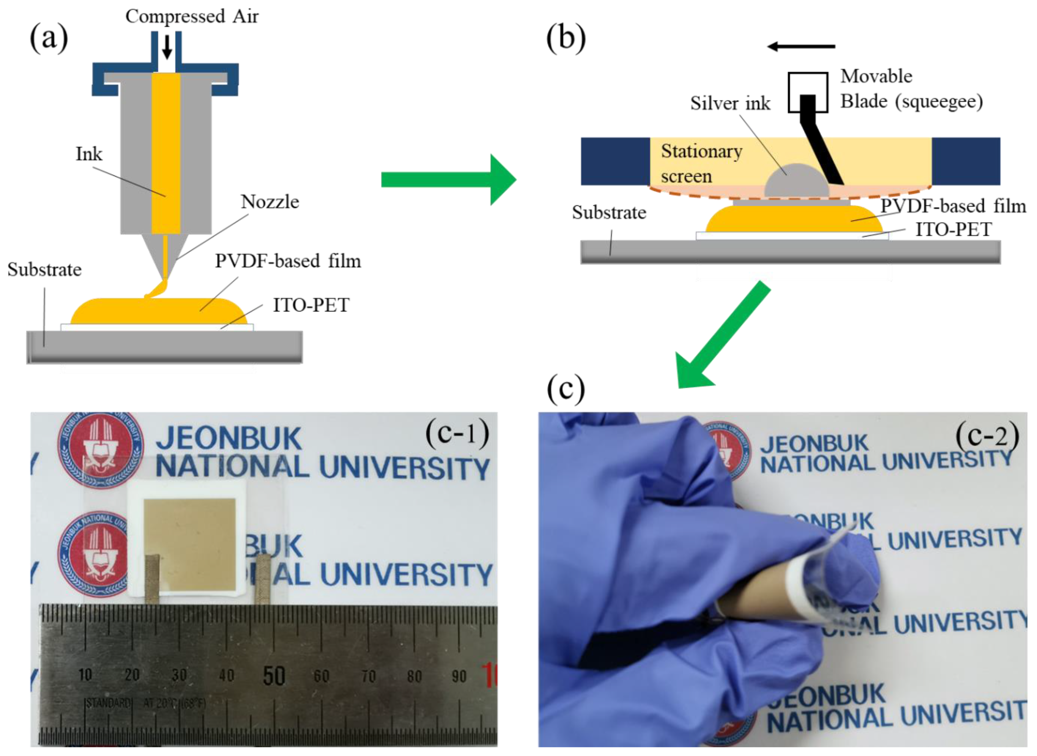
2.4. Preparation of PENGs
2.5. Measurement and Characterization
3. Results and Discussion
4. Conclusions
Supplementary Materials
Author Contributions
Funding
Institutional Review Board Statement
Informed Consent Statement
Data Availability Statement
Conflicts of Interest
References
- Javed, M.S.; Zhong, D.; Ma, T.; Song, A.; Ahmed, S. Hybrid pumped hydro and battery storage for renewable energy based power supply system. Appl. Energy 2020, 257, 114026. [Google Scholar] [CrossRef]
- Chow, P.C.Y.; Someya, T. Organic Photodetectors for Next-Generation Wearable Electronics. Adv. Mater. 2019, 32, e1902045. [Google Scholar] [CrossRef]
- Wang, C.; Xia, K.; Wang, H.; Liang, X.; Yin, Z.; Zhang, Y. Advanced carbon for flexible and wearable electronics. Adv. Mater. 2019, 31, e1801072. [Google Scholar] [CrossRef] [PubMed]
- Wang, X.; Song, J.; Liu, J.; Wang, Z.L. Direct-Current Nanogenerator Driven by Ultrasonic Waves. Science 2007, 316, 102–105. [Google Scholar] [CrossRef] [Green Version]
- Nabat, M.H.; Zeynalian, M.; Razmi, A.R.; Arabkoohsar, A.; Soltani, M. Energy, exergy, and economic analyses of an innovative energy storage system; liquid air energy storage (LAES) combined with high-temperature thermal energy storage (HTES). Energy Convers. Manag. 2020, 226, 113486. [Google Scholar] [CrossRef]
- Waibel, C.; Evins, R.; Carmeliet, J. Co-simulation and optimization of building geometry and multi-energy systems: Interdependencies in energy supply, energy demand and solar potentials. Appl. Energy 2019, 242, 1661–1682. [Google Scholar] [CrossRef]
- Ferrie, S.; Darwish, N.; Gooding, J.J.; Ciampi, S. Harnessing silicon facet-dependent conductivity to enhance the direct-current produced by a sliding Schottky diode triboelectric nanogenerator. Nano Energy 2020, 78, 105210. [Google Scholar] [CrossRef]
- Pi, Z.; Zhang, J.; Wen, C.; Zhang, Z.-B.; Wu, D. Flexible piezoelectric nanogenerator made of poly(vinylidenefluoride-co-trifluoroethylene) (PVDF-TrFE) thin film. Nano Energy 2014, 7, 33–41. [Google Scholar] [CrossRef]
- Zhao, H.; Xiao, X.; Xu, P.; Zhao, T.; Song, L.; Pan, X.; Mi, J.; Xu, M.; Wang, Z.L. Dual-Tube Helmholtz Resonator-Based Triboelectric Nanogenerator for Highly Efficient Harvesting of Acoustic Energy. Adv. Energy Mater. 2019, 9. [Google Scholar] [CrossRef]
- Li, J.; Liu, K.; Ding, T.; Yang, P.; Duan, J.; Zhou, J. Surface functional modification boosts the output of an evaporation-driven water flow nanogenerator. Nano Energy 2019, 58, 797–802. [Google Scholar] [CrossRef]
- Xia, K.; Zhu, Z.; Zhang, H.; Du, C.; Fu, J.; Xu, Z. Milk-based triboelectric nanogenerator on paper for harvesting energy from human body motion. Nano Energy 2019, 56, 400–410. [Google Scholar] [CrossRef]
- Nie, J.; Ren, Z.; Shao, J.; Deng, C.; Xu, L.; Chen, X.; Li, M.; Wang, Z.L. Self-Powered Microfluidic Transport System Based on Triboelectric Nanogenerator and Electrowetting Technique. ACS Nano 2018, 12, 1491–1499. [Google Scholar] [CrossRef] [PubMed]
- Aliqué, M.; Simão, C.D.; Murillo, G.; Moya, A. Fully-Printed Piezoelectric Devices for Flexible Electronics Applications. Adv. Mater. Technol. 2021, 6. [Google Scholar] [CrossRef]
- Yildirim, A.; Grant, J.C.; Es-Haghi, S.S.; Lee, W.; Maruthamuthu, M.K.; Verma, M.; Sutherland, J.W.; Cakmak, M. Roll-to-Roll (R2R) Production of Large-Area High-Performance Piezoelectric Films Based on Vertically Aligned Nanocolumn Forests. Adv. Mater. Technol. 2020, 5. [Google Scholar] [CrossRef]
- Zhang, J.; Ye, S.; Liu, H.; Chen, X.; Chen, X.; Li, B.; Tang, W.; Meng, Q.; Ding, P.; Tian, H.; et al. 3D printed piezoelectric BNNTs nanocomposites with tunable interface and microarchitectures for self-powered conformal sensors. Nano Energy 2020, 77, 105300. [Google Scholar] [CrossRef]
- Verma, K.; Bharti, D.K.; Badatya, S.; Srivastava, A.K.; Gupta, M.K. A high performance flexible two dimensional vertically aligned ZnO nanodisc based piezoelectric nanogenerator via surface passivation. Nanoscale Adv. 2020, 2, 2044–2051. [Google Scholar] [CrossRef] [Green Version]
- Abubakar, S.; Khalid, N.; Rahman, S.F.A.; Tee, T.S.; Hamidon, M.N.; Talib, Z.A.; Sagadevan, S.; Paiman, S. Fabrication and characterization of nanostructured zinc oxide on printed microcontact electrode for piezoelectric applications. J. Mater. Res. Technol. 2020, 9, 15952–15961. [Google Scholar] [CrossRef]
- Rana, M.; Khan, A.A.; Huang, G.; Mei, N.; Saritas, R.; Wen, B.; Zhang, S.; Voss, P.; Abdel-Rahman, E.; Leonenko, Z.; et al. Porosity Modulated High-Performance Piezoelectric Nanogenerator Based on Organic/Inorganic Nanomaterials for Self-Powered Structural Health Monitoring. ACS Appl. Mater. Interfaces 2020, 12, 47503–47512. [Google Scholar] [CrossRef] [PubMed]
- Lu, L.; Ding, W.; Liu, J.; Yang, B. Flexible PVDF based piezoelectric nanogenerators. Nano Energy 2020, 78, 105251. [Google Scholar] [CrossRef]
- Lovinger, A.J. Ferroelectric Polymers. Science 1983, 220, 1115–1121. [Google Scholar] [CrossRef] [PubMed]
- Ueberschlag, P.; Ueberschlag, P. PVDF piezoelectric polymer. Sens. Rev. 2001, 21, 118–126. [Google Scholar] [CrossRef]
- Chen, S.; Li, X.; Yao, K.; Tay, F.E.H.; Kumar, A.; Zeng, K. Self-polarized ferroelectric PVDF homopolymer ultra-thin films derived from Langmuir–Blodgett deposition. Polymer 2012, 53, 1404–1408. [Google Scholar] [CrossRef]
- Zabek, D.; Seunarine, K.; Spacie, C.; Bowen, C. Graphene Ink Laminate Structures on Poly(vinylidene difluoride) (PVDF) for Pyroelectric Thermal Energy Harvesting and Waste Heat Recovery. ACS Appl. Mater. Interfaces 2017, 9, 9161–9167. [Google Scholar] [CrossRef] [PubMed] [Green Version]
- Martins, P.; Lopes, A.C.; Lanceros-Mendez, S. Electroactive phases of poly(vinylidene fluoride): Determination, processing and applications. Prog. Polym. Sci. 2014, 39, 683–706. [Google Scholar] [CrossRef]
- Ribeiro, C.; Correia, D.M.; Ribeiro, S.; Sencadas, V.; Botelho, G.; Lanceros-Méndez, S. Piezoelectric poly(vinylidene fluoride) microstructure and poling state in active tissue engineering. Eng. Life Sci. 2015, 15, 351–356. [Google Scholar] [CrossRef] [Green Version]
- Jeong, C.K.; Hyeon, D.Y.; Hwang, G.-T.; Lee, G.-J.; Lee, M.-K.; Park, J.-J.; Park, K.-I. Nanowire-percolated piezoelectric copolymer-based highly transparent and flexible self-powered sensors. J. Mater. Chem. A 2019, 7, 25481–25489. [Google Scholar] [CrossRef]
- Azimi, B.; Milazzo, M.; Lazzeri, A.; Berrettini, S.; Uddin, M.J.; Qin, Z.; Buehler, M.J.; Danti, S. Electrospinning Piezoelectric Fibers for Biocompatible Devices. Adv. Health. Mater. 2019, 9, e1901287. [Google Scholar] [CrossRef] [PubMed]
- Kim, H.; Torres, F.; Wu, Y.; Villagran, D.; Lin, Y.; Tseng, T.-L. Integrated 3D printing and corona poling process of PVDF piezoelectric films for pressure sensor application. Smart Mater. Struct. 2017, 26, 085027. [Google Scholar] [CrossRef]
- Mishra, S.; Sahoo, R.; Unnikrishnan, L.; Ramadoss, A.; Mohanty, S.; Nayak, S.K. Investigation of the electroactive phase content and dielectric behaviour of mechanically stretched PVDF-GO and PVDF-rGO composites. Mater. Res. Bull. 2020, 124, 110732. [Google Scholar] [CrossRef]
- Yin, Z.; Tian, B.; Zhu, Q.; Duan, C. Characterization and Application of PVDF and Its Copolymer Films Prepared by Spin-Coating and Langmuir–Blodgett Method. Polymers 2019, 11, 2033. [Google Scholar] [CrossRef] [Green Version]
- Kim, H.; Torres, F.; Villagran, D.; Stewart, C.; Lin, Y.; Tseng, T.B. 3D Printing of BaTiO3/PVDF Composites with Electric In Situ Poling for Pressure Sensor Applications. Macromol. Mater. Eng. 2017, 302. [Google Scholar] [CrossRef]
- Soin, N.; Boyer, D.; Prashanthi, K.; Sharma, S.; Narasimulu, A.A.; Luo, J.; Shah, T.H.; Siores, E.; Thundat, T. Exclusive self-aligned β-phase PVDF films with abnormal piezoelectric coefficient prepared via phase inversion. Chem. Commun. 2015, 51, 8257–8260. [Google Scholar] [CrossRef]
- Singh, D.; Choudhary, A.; Garg, A. Flexible and Robust Piezoelectric Polymer Nanocomposites Based Energy Harvesters. ACS Appl. Mater. Interfaces 2018, 10, 2793–2800. [Google Scholar] [CrossRef] [PubMed]
- Shepelin, N.A.; Sherrell, P.C.; Goudeli, E.; Skountzos, E.N.; Lussini, V.C.; Dicinoski, G.W.; Shapter, J.G.; Ellis, A.V. Printed recyclable and self-poled polymer piezoelectric generators through single-walled carbon nanotube templating. Energy Environ. Sci. 2019, 13, 868–883. [Google Scholar] [CrossRef]
- Jella, V.; Ippili, S.; Eom, J.-H.; Choi, J.; Yoon, S.-G. Enhanced output performance of a flexible piezoelectric energy harvester based on stable MAPbI3-PVDF composite films. Nano Energy 2018, 53, 46–56. [Google Scholar] [CrossRef]
- Thakur, P.; Kool, A.; Bagchi, B.; Das, S.; Nandy, P. Effect of in situ synthesized Fe2O3and Co3O4nanoparticles on electroactive β phase crystallization and dielectric properties of poly(vinylidene fluoride) thin films. Phys. Chem. Chem. Phys. 2014, 17, 1368–1378. [Google Scholar] [CrossRef] [PubMed]
- Ribeiro, S.; Meira, R.; Correia, D.M.; Tubio, C.R.; Ribeiro, C.; Baleizao, C.; Lanceros-Méndez, S. Silica nanoparticles surface charge modulation of the electroactive phase content and physical-chemical properties of poly(vinylidene fluoride) nanocomposites. Compos. Part B Eng. 2020, 185, 107786. [Google Scholar] [CrossRef]
- Jia, N.; Xing, Q.; Liu, X.; Sun, J.; Xia, G.; Huang, W.; Song, R. Enhanced electroactive and mechanical properties of poly(vinylidene fluoride) by controlling crystallization and interfacial interactions with low loading polydopamine coated BaTiO3. J. Colloid Interface Sci. 2015, 453, 169–176. [Google Scholar] [CrossRef] [PubMed]
- Zhou, T.; Zha, J.-W.; Cui, R.-Y.; Fan, B.-H.; Yuan, J.; Dang, Z.-M. Improving Dielectric Properties of BaTiO3/Ferroelectric Polymer Composites by Employing Surface Hydroxylated BaTiO3 Nanoparticles. ACS Appl. Mater. Interfaces 2011, 3, 2184–2188. [Google Scholar] [CrossRef]
- Li, H.; Song, H.; Long, M.; Saeed, G.; Lim, S. Mortise–tenon joint structured hydrophobic surface-functionalized barium titanate/polyvinylidene fluoride nanocomposites for printed self-powered wearable sensors. Nanoscale 2021, 13, 2542–2555. [Google Scholar] [CrossRef]
- Fu, J.; Hou, Y.; Zheng, M.; Wei, Q.; Zhu, M.; Yan, H. Improving Dielectric Properties of PVDF Composites by Employing Surface Modified Strong Polarized BaTiO3 Particles Derived by Molten Salt Method. ACS Appl. Mater. Interfaces 2015, 7, 24480–24491. [Google Scholar] [CrossRef]
- Yousry, Y.M.; Yao, K.; Mohamed, A.M.; Liew, W.H.; Chen, S.; Ramakrishna, S. Theoretical Model and Outstanding Performance from Constructive Piezoelectric and Triboelectric Mechanism in Electrospun PVDF Fiber Film. Adv. Funct. Mater. 2020, 30. [Google Scholar] [CrossRef]
- Lu, L.; Yang, B.; Zhai, Y.; Liu, J. Electrospinning core-sheath piezoelectric microfibers for self-powered stitchable sensor. Nano Energy 2020, 76, 104966. [Google Scholar] [CrossRef]
- Pan, X.; Wang, Z.; Cao, Z.; Zhang, S.; He, Y.; Zhang, Y.; Chen, K.; Hu, Y.; Gu, H. A self-powered vibration sensor based on electrospun poly(vinylidene fluoride) nanofibres with enhanced piezoelectric response. Smart Mater. Struct. 2016, 25, 105010. [Google Scholar] [CrossRef]
- Liu, J.; Yang, B.; Lu, L.; Wang, X.; Li, X.; Chen, X.; Liu, J. Flexible and lead-free piezoelectric nanogenerator as self-powered sensor based on electrospinning BZT-BCT/P(VDF-TrFE) nanofibers. Sensors Actuators A Phys. 2020, 303, 111796. [Google Scholar] [CrossRef]
- Sasmal, A.; Medda, S.K.; Devi, P.S.; Sen, S. Nano-ZnO decorated ZnSnO3 as efficient fillers in PVDF matrixes: Toward simultaneous enhancement of energy storage density and efficiency and improved energy harvesting activity. Nanoscale 2020, 12, 20908–20921. [Google Scholar] [CrossRef] [PubMed]
- Thakur, P.; Kool, A.; Hoque, N.A.; Bagchi, B.; Khatun, F.; Biswas, P.; Brahma, D.; Roy, S.; Banerjee, S.; Das, S. Superior performances of in situ synthesized ZnO/PVDF thin film based self-poled piezoelectric nanogenerator and self-charged photo-power bank with high durability. Nano Energy 2018, 44, 456–467. [Google Scholar] [CrossRef]
- Li, Q.; Ke, W.; Chang, T.; Hu, Z. A molecular ferroelectrics induced electroactive β-phase in solution processed PVDF films for flexible piezoelectric sensors. J. Mater. Chem. C 2019, 7, 1532–1543. [Google Scholar] [CrossRef]
- Pickford, T.; Gu, X.; Heeley, E.L.; Wan, C. Effects of an ionic liquid and processing conditions on the β-polymorph crystal formation in poly(vinylidene fluoride). CrystEngComm 2019, 21, 5418–5428. [Google Scholar] [CrossRef] [Green Version]
- Li, X.; Wang, Y.; Lu, X.; Xiao, C. Morphology changes of polyvinylidene fluoride membrane under different phase separation mechanisms. J. Membr. Sci. 2008, 320, 477–482. [Google Scholar] [CrossRef]
- Maciel, M.; Ribeiro, S.; Francesko, A.; Maceiras, A.; Vilas, J.; Lanceros-Mendez, S. Relation between fiber orientation and mechanical properties of nano-engineered poly(vinylidene fluoride) electrospun composite fiber mats. Compos. Part B Eng. 2018, 139, 146–154. [Google Scholar] [CrossRef]
- Benz, M.; Euler, W.; Gregory, O.J. The Role of Solution Phase Water on the Deposition of Thin Films of Poly(vinylidene fluoride). Macromolecules 2002, 35, 2682–2688. [Google Scholar] [CrossRef]
- Salimi, A.; Yousefi, A.A. Conformational changes and phase transformation mechanisms in PVDF solution-cast films. J. Polym. Sci. Part B Polym. Phys. 2004, 42, 3487–3495. [Google Scholar] [CrossRef]
- Guan, X.; Xu, B.; Gong, J. Hierarchically architected polydopamine modified BaTiO3@P(VDF-TrFE) nanocomposite fiber mats for flexible piezoelectric nanogenerators and self-powered sensors. Nano Energy 2020, 70, 104516. [Google Scholar] [CrossRef]
- Shi, K.; Sun, B.; Huang, X.; Jiang, P. Synergistic effect of graphene nanosheet and BaTiO3 nanoparticles on performance enhancement of electrospun PVDF nanofiber mat for flexible piezoelectric nanogenerators. Nano Energy 2018, 52, 153–162. [Google Scholar] [CrossRef]


| PVDF | BTO/PVDF | PDA-BTO/PVDF | PFD-BTO/PVDF | |
|---|---|---|---|---|
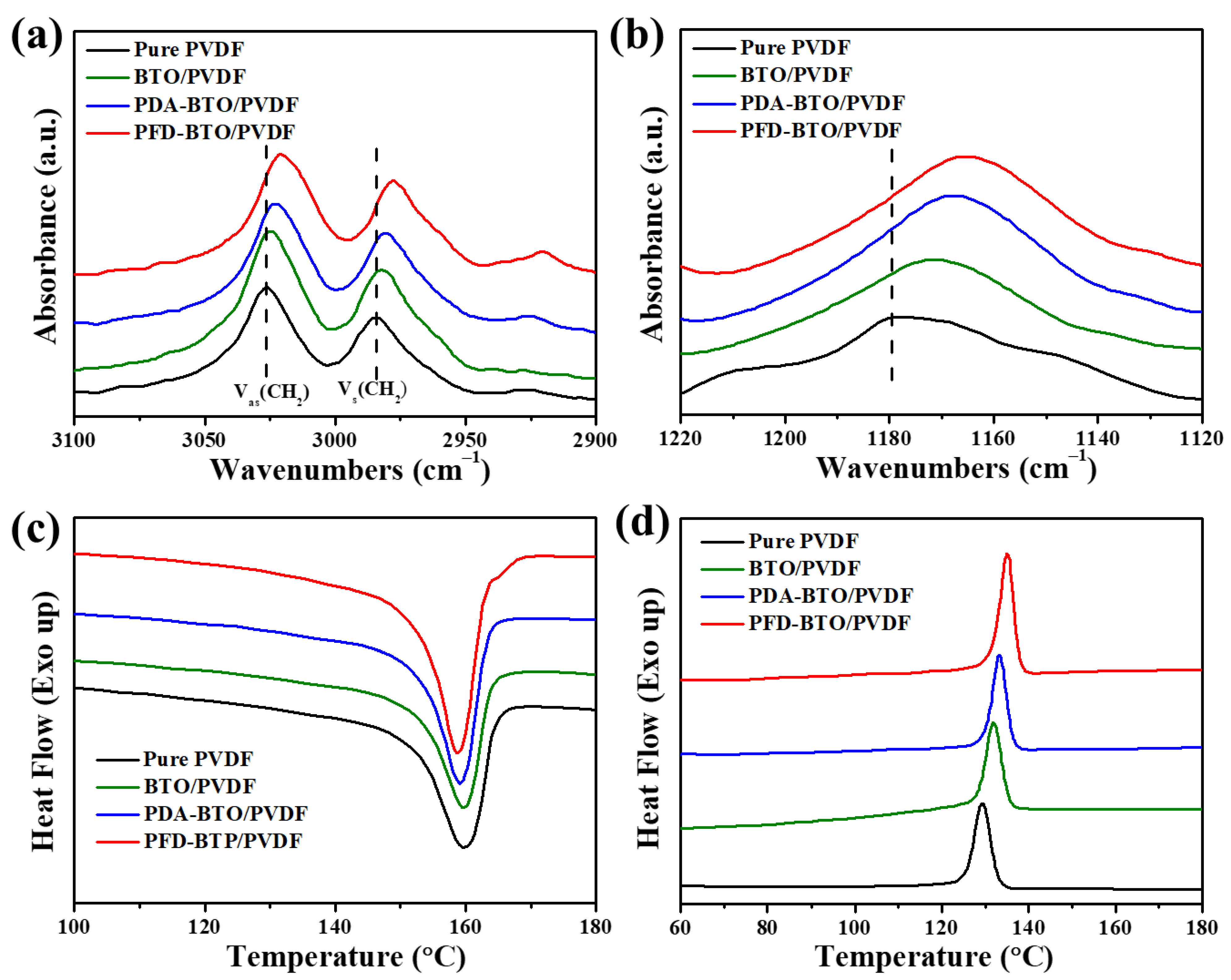
| ΔHm (J g−1) | 40.72 | 38.63 | 41.12 | 42.42 |
| Tm (°C) | 163.13 | 162.34 | 161.37 | 160.92 |
| Tc (°C) | 129.38 | 131.76 | 133.19 | 135.11 |
| ΔXc (%) | 38.89 | 40.11 | 42.69 | 44.04 |
| PVDF | BTO/PVDF | PDA-BTO/PVDF | PFD-BTO/PVDF | |
|---|---|---|---|---|
| E (MPa) | 878.54 ± 48 | 1048 ± 70 | 1257.04 ± 51 | 1442.28 ± 64 |
| σbreak (MPa) | 33.46 ± 1.34 | 34.54 ± 2.65 | 38.89 ± 3.48 | 45.83 ± 2.89 |
| εbreak (%) | 11.39 ± 1.32 | 11.90 ± 2.19 | 12.88 ± 1.95 | 15.33 ± 2.43 |
Publisher’s Note: MDPI stays neutral with regard to jurisdictional claims in published maps and institutional affiliations. |
© 2021 by the authors. Licensee MDPI, Basel, Switzerland. This article is an open access article distributed under the terms and conditions of the Creative Commons Attribution (CC BY) license (https://creativecommons.org/licenses/by/4.0/).
Share and Cite
Li, H.; Lim, S. Boosting Performance of Self-Polarized Fully Printed Piezoelectric Nanogenerators via Modulated Strength of Hydrogen Bonding Interactions. Nanomaterials 2021, 11, 1908. https://doi.org/10.3390/nano11081908
Li H, Lim S. Boosting Performance of Self-Polarized Fully Printed Piezoelectric Nanogenerators via Modulated Strength of Hydrogen Bonding Interactions. Nanomaterials. 2021; 11(8):1908. https://doi.org/10.3390/nano11081908
Chicago/Turabian StyleLi, Hai, and Sooman Lim. 2021. "Boosting Performance of Self-Polarized Fully Printed Piezoelectric Nanogenerators via Modulated Strength of Hydrogen Bonding Interactions" Nanomaterials 11, no. 8: 1908. https://doi.org/10.3390/nano11081908