Article

Exploring the Effect of Selenidation Time on the Ni-Doped Cu2ZnSn(S,Se)4 Solar Cell

1
Key Laboratory of Functional Materials Physics and Chemistry of Ministry of Education, Jilin Normal University, Changchun 130103, China
2
State Key Laboratory of Superhard Materials and College of Physics, Jilin University, Changchun 130012, China
*
Authors to whom correspondence should be addressed.
Nanomaterials 2022, 12(23), 4311; https://doi.org/10.3390/nano12234311
Submission received: 10 November 2022 / Revised: 28 November 2022 / Accepted: 1 December 2022 / Published: 5 December 2022
(This article belongs to the Special Issue Nanomaterials for Light Energy Harvesting and Photovoltaic Devices)

Abstract

:
The Cu2Ni0.05Zn0.95Sn(S,Se)4 (CNZTSSe) films were synthesized by sol-gel combined with selenidation treatment. To further enhance the crystal quality of the film, the selenidation conditions were optimized, and the effects of selenidation time on the properties of the CNZTSSe films and devices were systematically studied. The results show that the crystallinity of the films increased remarkably with the increase of selenidation time. Under the optimum selenidation time of 15 min, smooth and dense films were obtained. Through the analysis of EDS results, it is found that Se occupies more S positions with the increase of selenidation time, which decreases the band gap of the film from 1.14 eV to 1.0 eV. In addition, the formation of Zn-related defects is effectively suppressed by Ni doping to enhance the open circuit voltage (Voc) of the CNZTSSe solar cells. When the selenidation time is 15 min, the CNZTSSe film has the highest carrier concentration of 1.68 × 1016 cm−3, and the best efficiency of the device prepared based on the film as the absorption layer is 5.0%, and the Voc is 337 mV.

1. Introduction

Due to the high cost of silicon solar cells and the high requirements for the preparation process, photovoltaic cells based on thin film materials have emerged as the times require. There are mainly III or V groups of compound cells, such as gallium arsenide (GaAs), cadmium telluride (CdTe), copper indium selenium (CIS), copper indium gallium selenium (CIGS). CIGS thin film solar cells are the best of the second generation solar cells [1]. At the end of 2015, the German Renewable Energy Laboratory (ZSW) announced the preparation of CIGS thin film solar cells with an efficiency of 21.7% [2]. However, it contains rare elements such as indium (In) and gallium (Ga). Because of its low reserves and rising prices year by year, the cost of CIGS solar cells has greatly increased, severely limiting their large-scale application in practice. Therefore, the third-generation Cu2ZnSn(S,Se)4 (CZTSSe) thin-film photovoltaic material with kesterite structure has become the best substitute for CIGS thin film due to its non-toxic, low preparation cost, good stability, and high absorption coefficient [3,4,5]. At the same time, the structure of CZTSSe thin film solar cells has borrowed from the commercial CIGS thin film solar cells [6]. To verify the photovoltaic effect of CZTSSe thin films, Nitsche and other researchers first studied the crystal growth of Cu2ZnSnS4 (CZTS) compounds using vapor diffusion [7]. Later, Kentaro and other researchers studied the electrical and optical properties of CZTS with stannite structure for the first time, thus experimentally confirming that this kind of film has a photovoltaic effect [8]. IBM Company of the United States used the hydrazine solution method to deposit CZTSSe film, which made the efficiency of the device reach 12.6% [9]. However, the toxicity and explosiveness of hydrazine may limit its commercialization. The recent exciting method is that Xin et al. made a breakthrough by using a simple solution method to make the efficiency of CZTSSe thin film solar cells reach 13% [10]. However, its efficiency is still far lower than commercial CIGS thin film solar cells [11]. According to relevant literature reports, it is found that low Voc is the main bottleneck restricting the development of these solar cells [12].
The low Voc is usually caused by poor crystal quality, many inherent defects in the crystal, and poor energy band matching. Many experiments and theoretical calculations indicate that the main inherent defect in CZTSSe crystal is CuZn inversion [13,14]. Since the similar cation size of the two metal elements, high concentration CuZn corrosion resistance defects (CuZn disorder) will be formed, resulting in the emergence of band tail states, thus reducing the Voc [15]. One way to alleviate CuZn disorder is to make the absorber undergo disorder order transition by low-temperature annealing. However, the relevant literature shows that this method needs to be combined with high-temperature post-annealing, and the promotion effect on Voc is not obvious [16,17,18]. Another strategy to reduce CuZn defects is to partially replace Cu or Zn with isoelectronic elements with different ion sizes to effectively improve the Voc of the device, such as replacing copper with silver and zinc with cadmium [19,20,21]. However, the disadvantages of silver and cadmium substitution are high cost and toxicity. To avoid this problem, in our previous work, Ni atoms with non-toxic, abundant reserves, low cost, and close to the radius of zinc ions were introduced into the CZTSSe lattice, and CNZTSSe thin films were obtained [22]. CNZTSSe thin films were used as an absorption layer to prepare CNZTSSe solar cells. The results indicate that the device properties and efficiency are significantly improved at the appropriate concentration of Ni doping. It is well known that selenidation conditions are very important for the grain growth of thin films [23,24,25]. To further obtain high-quality CNZTSSe devices, it is no doubt to optimize the selenidation conditions. Up to now, the effect of the selenidation time on the structural and photoelectric characteristics of CNZTSSe films, as well as the performance of devices, has not been reported.
This work is the first time selenizing CNZTS precursor films synthesized a series of CNZTSSe films at different selenidation times. The impacts of selenidation time on the crystallization, optical and electrical performances of CNZTSSe films were systematically studied. Meanwhile, the influence of selenidation time on the photovoltaic property of CNZTSSe devices was also studied by adjusting the selenidation time. Finally, CNZTSSe solar cells with a photoelectric conversion efficiency of 5% were obtained by optimizing the selenidation time.

2. Experimental Section

2.1. Materials

The Cu2Ni0.05Zn0.95SnS4 (CNZTS) film was deposited on Mo deposited glass substrate (Mo-SLG) by sol-gel means. Firstly, the precursor solution of CZTS was obtained by dissolving 1.1979 g Cu(CH3COO)2·H2O (99.9%), 0.5693 g ZnCl2, 0.8462 g SnCl2·2H2O (99.9%), 0.0639g NiNO3·6H2O (99.9%) and 2.2836 g thiourea (99.9%) in 10 mL dimethyl sulfoxide. Ethanolamine (MEA) was selected as the stabilizer of the precursor solution. The doping concentration of Ni in the precursor solution is 0.05. The clear, light green solution was obtained by heating and stirring. CNZTS precursor solution was coated on Mo-SLG substrate at 3000 rpm for 30 s, then annealed at low temperature in a nitrogen atmosphere for 3 min to prepare CNZTS thin films. To meet the experimental requirements for the optimal thickness of 900 nm, it is necessary to repeat rotary coating and dry it ten times. Finally, the thin films were annealed in the graphite box using 0.02 mg Se powder (Figure 1). Figure 1 shows various components of a rapid thermal annealing furnace, including the halogen lamp, graphite box, and quartz tube. The selenization annealing treatment was divided into two steps. First, the temperature was raised to 200 °C after 80 s at room temperature, and then the temperature was raised to 540 °C after 135 s. The CZTSSe film was formed at this temperature for 900 s. The best CNZTSSe film can be obtained by adjusting the selenidation time under a selenidation temperature of 540 °C.

2.2. Fabrication

A 60 nm CdS buffer layer was synthesized on the surface of the CNZTSSe thin film absorption layer using the chemical bath deposition method. The 50 nm ZnO and 250 nm ITO window layers were synthesized on the CdS buffer layer by magnetron sputtering. The Ag top electrode was deposited on the ITO layer by evaporation technique. Thus, CNZTSSe devices with SLG/Mo/CNZTSSe (x = 0.05)/CdS/i-ZnO/ITO/Ag traditional structure were obtained.

2.3. Characterization

The crystal structure of CNZTSSe films was studied by X-ray diffraction (XRD) and Raman spectroscopy. The types and contents of elements in films were determined by X-ray photoelectron spectroscopy (XPS) and energy dispersive spectroscopy (EDS) systems. Using scanning electron microscopy (SEM) to characterize the morphology of CNZTSSe films. The optical and electrical performances of the films were characterized via ultraviolet-visible near infrared spectrophotometer (UV-3101pc, Tokyo, Japan) and Hall test. The photovoltaic performance of the device was characterized by the current density voltage (J-V) curve and external quantum efficiency (EQE) curve (zolix solar cell scoan100) test.

3. Results and Discussion

3.1. Effect of Selenidation Time on the Structure and Morphology of Thin Films

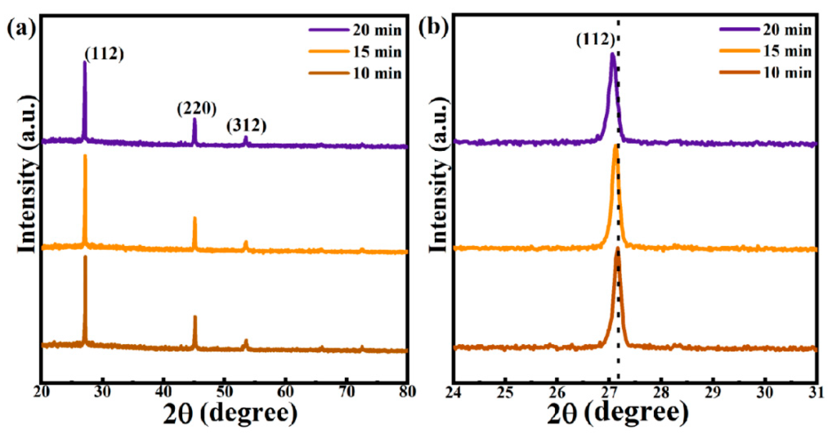
The precursor film was deposited on Mo-SLG substrate using CNZTS solution and annealed at low temperature. Then, the CNZTS film was selenized to form the CNZTSSe absorption layer film. The selenidation procedure is the same as preparing the CZTSSe films [26]. The selenidation temperature of CNZTS is 540 °C instead of a higher temperature to avoid decomposition [27]. Figure 2a exhibits the XRD patterns of CNZTSSe films prepared under different selenidation times. In the whole spectrum, the diffraction peaks at 27.06°, 45.04°, and 53.48° belong to the crystal plane diffraction peaks of the CZTSSe phase, and the corresponding crystal planes are (112), (220), and (312), respectively. No characteristic peaks of other impurity phases are observed [28]. It means that the pure phase CNZTSSe film was obtained. In addition, the peak intensity reached the maximum value when the selenidation time was 15 min. This confirmed that the crystallinity of the CNZTSSe phase was improved by adjusting the selenidation time. Figure 2b shows an enlarged image of the (112) peaks. It can be more clearly observed that the (112) peak position shifts to a small angle with the extension of selenidation time, indicating that the larger Se atom replaces the smaller S atom in CNZTSSe film. The half peak width (FWHM), peak position (2θ), and peak intensity of the (112) main peak are integrated into Figure 3.
According to the changing trend of the curve in Figure 3, it is intuitively observed that FWHM, 2θ, and peak intensity changed significantly. As the selenidation time increases from 10 min to 15 min, the corresponding FWHM decreases gradually, and the corresponding peak intensity gradually increases, which strongly demonstrates that the crystallinity of the film was improved. As the selenidation time reached 15 min, the peak intensity reached the maximum, and the FWHM was the narrowest. However, as the selenidation time was raised to 20 min, the peak intensity decreased significantly, and FWHM widened. This may be due to the increase in selenidation time and large holes on the film surface. In addition, the 2θ value gradually shifts to a smaller angle with the extension of selenidation time, which can be more intuitively observed in Figure 1. This can be attributed to the fact that the degree of substitution of Se increases with the selenidation time because the radius of the Se ion is greater than that of the S ion.
To explore the impact of selenidation time on the structure of the film, the lattice constants a, c, and lattice volume (V) of the thin film were obtained by analyzing and calculating the XRD test results. The lattice parameters of the tetragonal structure can be calculated by this formula
1 d hkl 2 = h 2 + k 2 a 2 + l 2 c 2
where dhkl is the distance between (hkl) crystal planes. Figure 4a shows the lattice structure of CNZTSSe. It can be seen that Ni replaces the Zn position, and Se replaces the S position. Figure 4b,c shows that the lattice constants a and c gradually increased with the selenidation time, and the V of the corresponding films expanded. This further confirms that the larger Se replaces the smaller S. In addition, the corresponding η value of the film is obtained by calculating the c/2a. It can be found from Figure 4c that the values of η are less than 1. The structure study of Quaternary chalcogenide semiconductors displays that the η > 1 and η < 1 represent stannite and kesterite structures separately [29]. Therefore, it was proved that the CNZTSSe films prepared at different selenidation times have a kesterite structure.
Although the XRD patterns confirmed the formation of the kesterite CZTSSe phase, the peaks could not be distinguished between CZTSSe and secondary phases like CuxS, cubic ZnS, and tetragonal Cu2SnS3 because of their similar lattice parameters [30]. To further analyze the purity of the film phase, the Raman test was carried out to distinguish between these secondary phases and kesterite CZTSSe. The Raman spectra of the films prepared at the selenidation time of 10, 15, and 20 min are shown in Figure 5a. The Raman spectra have three vibration peaks at 165, 189, and 235 cm−1, respectively, corresponding to A (2), A (1), and E vibration modes. The three vibration peaks originate from the CZTSSe phase with a kesterite structure [31]. No peaks of other impurity phases were detected in the spectrum, which confirmed that all CNZTSSe films have kesterite structures. In addition, the film with a selenidation time of 15 min showed a strong characteristic peak at 189 cm−1. Therefore, it was concluded that 15 min was the optimal selenidation time for forming pure phase CNZTSSe. Figure 5b shows the changes in peak positions of three vibration modes with selenidation time. Among three vibration peaks, the peak position of A (1) vibration mode changes significantly, which has a redshift with increased selenidation time (Figure 5c). This phenomenon is interpreted as that with the increase of selenidation time, the amount of Se atoms increases in the film, which may cause new interactions. So, the chemical bond vibration is weakened to make the Raman peak red shift [32].
Figure 6 indicates the XPS spectra of all elements in the CNZTSSe films at the optimum selenidation time (15 min). Figure 6a displays the XPS spectrum of Cu 2p core energy level. The Cu 2p 3/2 and Cu 2p 1/2 peaks were obtained at 931.5 and 951.4 eV, and the peak position difference was 19.9 eV. This difference value is consistent with the binding energy of Cu2+, indicating that the Cu is + 2 valence in the film [33]. Figure 6b displays the XPS spectrum of Sn 3d core energy level. The two peaks of Sn 3d are located at 486.4 eV and 494.8 eV, with a binding energy difference of 8.4 eV. Therefore, the above two peaks are tetravalent Sn 3d 5/2 and Sn 3d 3/2 (Sn+4), separately [34]. Figure 6c displays the peaks of Zn 2p 3/2 and Zn 2p 1/2 at 1021.7 eV and 1044.8 eV. The peak level difference is 23.1 eV, which conforms to the binding energy of Zn2+, indicating that Zn exists at + 2 valence in the film [35]. The XPS spectrum of S 2p (Figure 6d) indicates the four peaks of S 2p 3/2, S 2p 1/2, Se 3p 3/2, and Se 3p 1/2, located at 160.3 eV, 161.2 eV, 159.7eV and 166.0eV, separately. The two peaks at 160.3 eV and 161.2 eV have a binding energy difference of 0.9 eV [36]. This agrees with the 160–164 eV range of S2−, revealing that the valence state of S is + 2 [36]. The Se 3d 3/2 and Se 3d 1/2 peaks are respectively located at 54.04 and 54.7 in Figure 6e. The split value is consistent with the binding energy value of Se2− [37]. In Figure 6f, Ni 2p 3/2 and Ni 2p 1/2 core levels with a peak separation of 17.5 eV were observed at 852.9 and 870.4 eV, respectively, indicating that Ni atoms with a valence state of + 2 have been successfully doped into CZTSSe films [38]. In addition, there are two satellite vibration peaks in the XPS spectrum of the Ni 2p core level, which does not affect the results of Ni valence analysis [39]. XPS test displays that the constituent elements CNZTSSe film exist in the forms of Cu+, Zn2+, Sn4+, S2−, Se2−, and Ni2+.
The element contents in the films with different selenidation times were determined by EDS measurement. The test results are shown in Table 1. After selenidation treatment, the Cu/(Zn + Ni + Sn) and Zn + Ni/Sn ratio in the films are unchanged. The value of Ni/(Ni + Zn) in all films has little change, which reveals that the effect of selenidation time on Ni doping content is weak. The most obvious change is the negative correlation between S and Se elements in the film. It means that Se replaces more S in the lattice as the increase of selenidation time, which leads to a significant increase in the content of Se. The increase of Se content helps to reduce the band gap of the film, which will be proved later. In addition, it can be found from Table 1 that the Se + S content reaches 50%. It means that the film is in a selenium-rich environment at this time.
Figure 7a–c displays the surface SEM images of CNZTSSe films prepared separately at selenidation times of 10, 15, and 20 min. It can be observed that the grain size of the film reaches the micron level from the nano level with the increase of selenidation time. When the selenidation time is 10 min, the surface grain of the film is small, the surface is rough, and there are many holes (Figure 7a). Figure 7b displays that the film is composed of large particles. It has a smooth and dense surface and almost no holes when the selenidation time reaches 15 min. However, when the selenidation time is further increased to 20 min, although the grain size of the film is large, some holes can be seen on its surface (Figure 7c), which is not conducive to carrier transport. The results show that the increase in the selenidation time can promote grain growth, and the optimal selenidation time is 15 min. A longer selenidation time may lead to the decomposition of the CNZTSSe phase and increase the pores on the surface of the film [40].

3.2. Effect of Selenidation Time on Optical and Electrical Properties of Thin Films

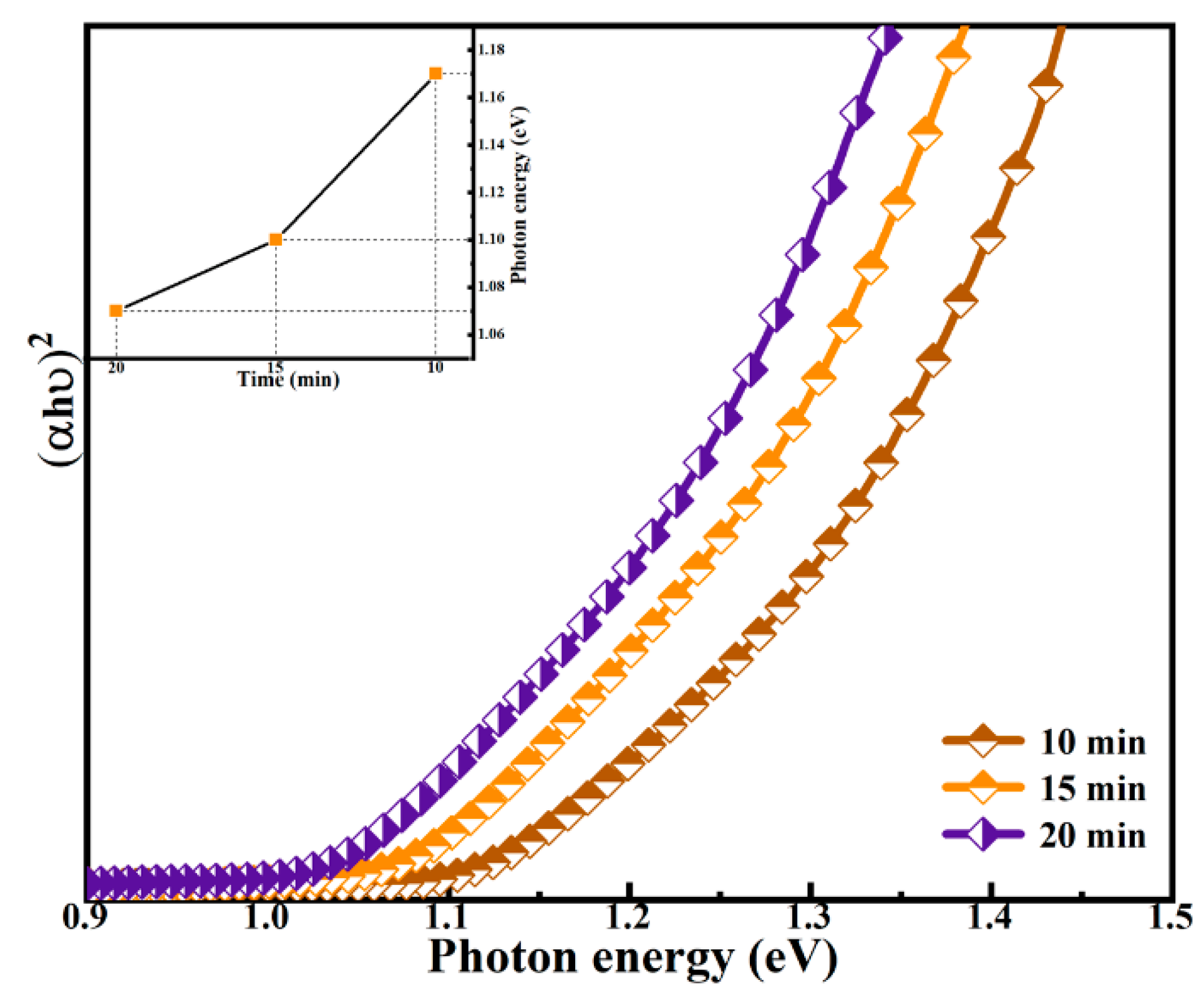
The curves of (αhυ)2 versus the photon energy (hυ) for the selenided films at the selenidation time of 10, 15, and 20 min were drawn in Figure 8. The absorption spectrum of the films was processed by using the Tuac’s relation (1), and the optical band gaps of the films were obtained.
(αhυ) = B(Eg)1/2
The α is the optical absorption coefficient, B is the Planck constant, and is the photon energy. The intercept between the tangent of the curve and the x-axis is the Eg value in Figure 8. The Eg values of all films are summarized in the illustration of Figure 8. The Eg values are estimated to be 1.17, 1.10, and 1.07 eV for the CNZTSSe films at the selenidation time of 10, 15, and 20 min, separately. As the increase of selenidation time, the substitution of Se for S in the film increases, resulting in a decrease in S content. As the decrease of S content, the scattering of electrons in the forbidden band at the grain boundary weakens, which will promote the transition of electrons in the forbidden band, thus reducing the Eg value [41]. On the other hand, according to the first principle calculation, the valence band maximum (VBM) of CZTS (CZTSe) is mainly related to S 3p (Se 4p) and Cu 3d orbital hybridization. The conduction band minimum (CBM) is mainly related to S 3p (Se 4p) and Sn 3d orbital hybridization [42]. However, when S is replaced by Se and Se content increases, the orbital interaction between CBM and VBM decreases, thereby reducing the Eg [43]. The results mean that adjusting selenidation time is an effective means to adjust the Eg of CNZTSSe films.
The electrical performances of CNZTSSe films were studied by Hall measurement, and the test results were recorded in Table 2. The Hall results demonstrated that irrespective of the dwell time during the selenidation process, all films exhibited p-type conductivity. As the increase of selenidation time from 10 to 15 min, the carrier concentration increased from 1.21 × 10¹⁶ to 1.68 × 1016 cm–3. Meanwhile, the mobility increased from 3.39 to 3.78 cm2V−1s−1, and the resistivity reduced from 9.98 × 10² Ω·cm to 1.51 × 10² Ω·cm. Then, when the selenidation time extended to 20 min, the carrier concentration decreased slightly to 1.66 × 1016 cm–3, the mobility decreased to 2.12 cm2V−1s−1, and the resistivity increased to 1.75 × 10² Ω·cm (see Table 2). Owing to the increase of the crystallinity and the decrease of grain boundary in the film with the increase of selenidation time to 15 min, increasing carrier concentration and mobility and decreasing resistivity. As the selenidation time increased to 20 min, the quality of the film became worse, which was characterized by large holes, rough surfaces, and increased grain boundaries. This worsens the overall electrical performance of the film. Hence, based on the above analysis, the electrical performance of the film is the best at the selenidation time of 15 min, which meets the requirements of the ideal absorption layer of CNZTSSe solar cells.

3.3. Effect of Selenidation Time on Device Performance

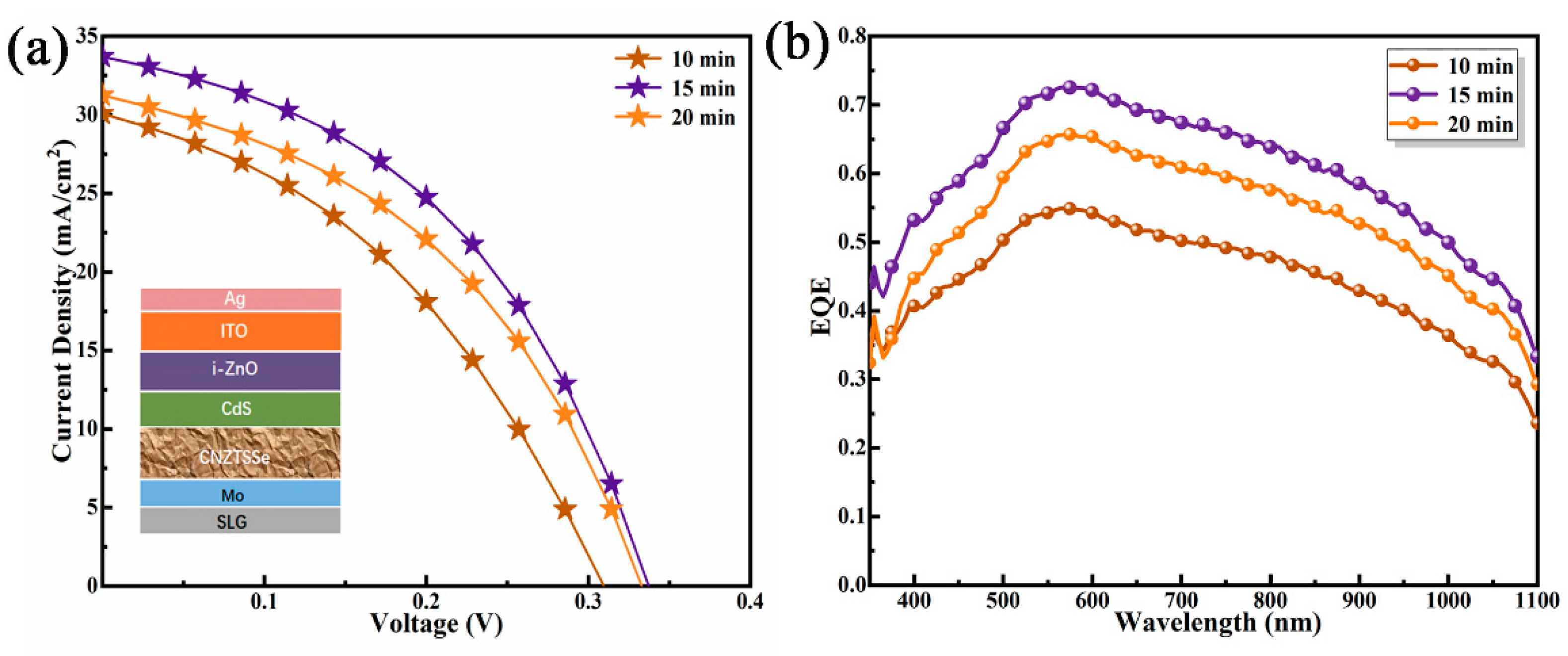
CNZTSSe solar cells with a conventional structure were illustrated in Figure 9a inset. Figure 9a displays the J-V curves of the CNZTSSe solar cells. The main photovoltaic parameters were recorded in Table 3. It displays that the photoelectric conversion efficiency (PCE) increases from 3.6% to 5.0% as the increase of selenidation time from 10 to 15 min. As the selenidation time was raised to 20 min, PCE decreased to 4.4%. Moreover, it can be found that other device parameters of the three devices, such as Voc, filling factor (FF), short-circuit current density (Jsc), and shunt resistance (RSh), which have similar variation laws with PCE. They all increased sharply as the increase of selenidation time from 10 to 15 min and then decreased from 15 to 20 min. The change law of series resistance (RS) with selenidation time shows an opposite trend. The device has the best performance parameters when the selenidation time is 15 min. The Voc, Jsc, and FF are 337 mV, 33.61 mA/cm2, and 44.15%. The corresponding Rs and Rsh are 1.86 Ωcm2 and 253.05 Ωcm2, respectively. The curve of the relevant device performance parameters of the devices is shown in Figure 10. When the selenidation time is in the range of 10–15 min, there is a decrease in RS and an increase in RSh. This is due to the enhancement of the electrical properties and quality of the device and the reduction of SnZn and CuZn defects by replacing Zn with Ni in the absorption layer [44]. The decrease in RS and the increase in RSh will enhance FF and Jsc [45]. When the selenidation is 15 min, the CNZTSSe has the best crystal quality. The RSh reached a maximum, and RS had a minimum. Meanwhile, the CNZTSSe device obtained the highest PCE. Therefore, it is concluded that the change of the PCE with selenidation time is mainly decided by the variation of RS and RSh, which is relevant to the defect density and crystal quality of CNZTSSe films.
Figure 9b displays the external quantum efficiency (EQE) of CNZTSSe solar cells at selenidation times of 10, 15, and 20 min, respectively. Comparing the EQE spectra of the three devices at short wavelengths (less than 500 nm), it can be found that the optical response is significantly enhanced for the device with a selenidation time of 15 min. This indicates that the absorption from the CdS/i-ZnO/ITO top layer may be improved [45]. When the EQE spectrum extends to a longer wavelength region, the optical response of the device increases as the increase of selenidation time from 10 to 15 min. For the device with a selenidation time of 15 min, the overall enhancement of the EQE spectrum can be attributed to the ideal crystal quality of the CNZTSSe film and less carrier recombination [46]. When the selenidation time further increases to 20 min, the optical response of the device decreases, which can be explained by the poor crystal quality of the absorption layer and the reduction of carrier transmission efficiency. The above analysis of EQE spectrums demonstrates that the CNZTSSe device with a selenidation time of 15 min performs best in collecting photogenerated carriers.

4. Conclusions

To summarize, we have synthesized a series of CNZTSSe thin films for the first time by selenizing CNZTS precursor films at different times, and successfully prepared CNZTSSe solar cells. Optimizing the selenidation time improved the performance of CNZTSSe films and devices. The results show that CNZTSSe film has high crystallinity, large grain size, and good electrical properties when the selenidation time is 15 min. In addition, the Eg of the CNZTSSe film is continuously adjustable with the change of selenidation time. As the selenidation time is 15 min, the PCE of the CNZTSSe device reaches the optimal value of 5%. The improvement of PCE is primarily due to the enhancement of crystal quality, the reduction of carrier recombination at grain boundaries, and good carrier collection ability. Based on the above research, optimizing the selenidation time of the absorption layer films provides a new idea for obtaining high-quality CNZTSSe solar cells.

Author Contributions

Conceptualization, Y.S. and J.W.; Writing-Original Draft Preparation, F.Z.; Software, M.M., N.Z. and T.W.; Formal analysis, Y.S. and G.C.; Investigation, J.W. and F.Z.; Writing-Review & Editing, M.M., N.Z. and B.Y. All authors have read and agreed to the published version of the manuscript.

Funding

This research was funded by the Program for the development of Science and Technology of Jilin province Grant Nos. 20210101410JC, 20210509050RQ.

Data Availability Statement

Not applicable.

Conflicts of Interest

There are no conflicts to declare.

References

  1. Wang, W.; Su, Y.W.; Chang, C.H. Inkjet printed chalcopyrite CuInxGa1-xSe2 thin film solar cells. Sol. Energy Mater. Sol. Cells 2011, 95, 2616–2620. [Google Scholar] [CrossRef]
  2. Jackson, P.; Hariskos, D.; Wuerz, R.; Kiowski, O.; Bauer, A.; Friedlmeier, T.M.; Powalla, M. Properties of Cu(In,Ga)Se2 solar cells with new record efficiencies up to 21.7%. Phys. Status Solidi (RRL) 2015, 9, 28–31. [Google Scholar] [CrossRef]
  3. Shockley, W.; Queisser, H.J. Defect Engineering in Multinary Earth-Abundant Chalcogenide Photovoltaic Materials. J. Appl. Phys. 1961, 32, 510. [Google Scholar] [CrossRef]
  4. Shin, D.; Saparov, B.; Mitzi, D.B. Detailed Balance Limit of Efficiency of p-n Junction Solar Cells. Adv. Energy Mater. 2017, 7, 29. [Google Scholar]
  5. Fan, P.; He, Y.; Liang, G.; Xie, Z.; Yu, Z.; Lin, J.; Chen, S.; Zheng, Z.; Luo, J.; Su, Z. Enhancing Ag-alloyed Cu2ZnSnS4 solar cell performance by interfacial modification via In and Al. J. Mater. Chem. A 2021, 9, 25196–25207. [Google Scholar] [CrossRef]
  6. Bag, S.; Gunawan, O.; Gokmen, T.; Zhu, Y.; Todorov, T.K.; Mitzi, D.B. Low band gap liquid-processed CZTSe solar cell with 10.1% efficiency. Energy Environ. Sci. 2012, 5, 5. [Google Scholar] [CrossRef]
  7. Nitsche, R.; Sargent, D.F.; Wild, P. Crystal growth of quaternary 122464 chalcogenides by iodine vapor transport. J. Cryst. Growth 1967, 1, 52–53. [Google Scholar] [CrossRef]
  8. Ito, K.; Nakazawa, T. Electrical and Optical Properties of Stannite-Type Quaternary Semiconductor Thin Films. Jpn. J. Appl. Phys. 1988, 27, 2094–2097. [Google Scholar] [CrossRef]
  9. Son, D.H.; Kim, S.H.; Kim, S.Y.; Kim, Y.I.; Sim, J.H.; Park, S.N.; Kim, D.H. Effect of solid-H2S gas reactions on CZTSSe thin film growth and photovoltaic properties of a 12.62% efficiency device. J. Mater. Chem. A 2019, 7, 25279–25289. [Google Scholar] [CrossRef] [Green Version]
  10. Gong, Y.C.; Qiu, R.C.; Niu, C.Y.; Fu, J.J.; Jedlicka, E.; Giridharagopal, R.; Zhu, Q.; Zhou, Y.G.; Yan, W.B.; Yu, S.T.; et al. Ag Incorporation with Controlled Grain Growth Enables 12.5% Efficient Kesterite Solar Cell with Open Circuit Voltage Reached 64.2% Shockley-Queisser Limit. Adv. Funct. Mater. 2021, 31, 11. [Google Scholar] [CrossRef]
  11. Nakamura, M.; Yamaguchi, K.; Kimoto, Y.; Yasaki, Y.; Kato, T.; Sugimoto, H. Cd-Free Cu(In,Ga)(Se,S)2 Thin-Film Solar Cell With Record Efficiency of 23.35 %. IEEE J. Photovolt. 2019, 9, 1863–1867. [Google Scholar] [CrossRef]
  12. Green, M.; Dunlop, E.; Hohl-Ebinger, J.; Yoshita, M.; Kopidakis, N.; Hao, X.J. Solar cell efficiency tables (version 57). Prog. Photovolt. 2021, 29, 3–15. [Google Scholar] [CrossRef]
  13. Chen, S.Y.; Walsh, A.; Gong, X.G.; Wei, S.H. Classification of Lattice Defects in the Kesterite Cu2ZnSnS4 and Cu2ZnSnSe4 Earth-Abundant Solar Cell Absorbers. Adv. Mater. 2013, 25, 1522–1539. [Google Scholar] [CrossRef]
  14. Han, D.; Sun, Y.Y.; Bang, J.; Zhang, Y.Y.; Sun, H.B.; Li, X.B.; Zhang, S.B. Deep electron traps and origin of p-type conductivity in the earth-abundant solar-cell material Cu2ZnSnS4. Phys. Rev. B 2013, 87, 155206. [Google Scholar] [CrossRef] [Green Version]
  15. Zhou, J.Z.; Xu, X.; Duan, B.W.; Wu, H.J.; Shi, J.J.; Luo, Y.H.; Li, D.M.; Meng, Q.B. Regulating crystal growth via organic lithium salt additive for efficient Kesterite solar cells. Nano Energy 2021, 89, 12. [Google Scholar] [CrossRef]
  16. Rey, G.; Redinger, A.; Ler, J.S.; Weiss, T.P.; Thevenin, M.; Guennou, M.; El Adib, B.; Siebentritt, S. The band gap of Cu2ZnSnSe4: Effect of order-disorder. Appl. Phys. Lett. 2014, 105, 4. [Google Scholar] [CrossRef]
  17. Scragg, J.J.S.; Choubrac, L.; Lafond, A.; Ericson, T.; Platzer-Bjorkman, C. A low-temperature order-disorder transition in Cu2ZnSnS4 thin films. Appl. Phys. Lett. 2014, 104, 4. [Google Scholar] [CrossRef] [Green Version]
  18. Lang, M.; Renz, T.; Opolka, A.; Zimmermann, C.; Krammer, C.; Neuwirth, M.; Kalt, H.; Hetterich, M. Impact of the degree of Cu-Zn order in Cu2ZnSn(S,Se)4 solar cell absorbers on defect states and band tails. Appl. Phys. Lett. 2018, 113, 5. [Google Scholar] [CrossRef]
  19. Cabas-Vidani, A.; Haass, S.G.; Andres, C.; Caballero, R.; Figurei, R.; Schreiner, C.; Marquez, J.A.; Hages, C.; Unold, T.; Bleiner, D.; et al. High-Efficiency (LixCu1-x)2ZnSn(S,Se)4 Kesterite Solar Cells with Lithium Alloying. Adv. Energy Mater. 2018, 8, 8. [Google Scholar] [CrossRef]
  20. Yuan, Z.K.; Chen, S.Y.; Xiang, H.J.; Gong, X.G.; Walsh, A.; Park, J.S.; Repins, I.; Wei, S.H. Engineering Solar Cell Absorbers by Exploring the Band Alignment and Defect Disparity: The Case of Cu- and Ag-Based Kesterite Compounds. Adv. Funct. Mater. 2015, 25, 6733–6743. [Google Scholar] [CrossRef]
  21. Su, Z.H.; Tan, J.M.R.; Li, X.L.; Zeng, X.; Batabyal, S.K.; Wong, L.H. Cation Substitution of Solution-Processed Cu2ZnSnS4 Thin Film Solar Cell with over 9% Efficiency. Adv. Energy Mater. 2015, 5, 7. [Google Scholar] [CrossRef]
  22. Zeng, F.; Sui, Y.; Ma, M.; Zhao, N.; Wang, T.; Yang, L.; Wang, Z.W.; Wang, F.; Yao, B. Strengthening the Properties of Earth-Abundant Cu2ZnSn(S,Se)4 Photovoltaic Materials via Cation Incorporation with Ni. ACS Appl. Energ. Mater. 2022, 5, 1271–1281. [Google Scholar] [CrossRef]
  23. Marquez-Prieto, J.; Yakushev, M.V.; Forbes, I.; Krustok, J.; Edwards, P.R.; Zhivulko, V.D.; Borodavchenko, O.M.; Mudryi, A.V.; Dimitrievska, M.; Izquerdo-Roca, V.; et al. Impact of the selenisation temperature on the structural and optical properties of CZTSe absorbers. Sol. Energy Mater. Sol. Cells 2016, 152, 42–50. [Google Scholar] [CrossRef] [Green Version]
  24. Son, D.H.; Kim, Y.I.; Kim, S.H.; Nam, D.; Cheong, H.; Kang, J.K.; Yang, K.J.; Kim, D.H. Effects of S and Se contents on the physical and photovoltaic properties of Cu2ZnSn(Sx, Se1-x)4 thin films: Achieving a PCE of 9.47 %. J. Mater. Chem. A 2019, 7, 22986–22995. [Google Scholar] [CrossRef]
  25. Chen, G.; Li, J.; Wu, M.; Liu, J.; Lai, F.; Zhu, C. Effect of post sulfurization temperature on the microstructure of Cu2ZnSn(S,Se)4 thin film. Mater. Lett. 2015, 159, 32–34. [Google Scholar] [CrossRef]
  26. Xiao, Z.Y.; Yao, B.; Li, Y.F.; Ding, Z.H.; Gao, Z.M.; Zhao, H.F.; Zhang, L.G.; Zhang, Z.Z.; Sui, Y.R.; Wang, G. Influencing Mechanism of the Selenization Temperature and Time on the Power Conversion Efficiency of Cu2ZnSn(S,Se)4-Based Solar Cells. ACS Appl. Mater. Interfaces 2016, 8, 17334–17342. [Google Scholar] [CrossRef]
  27. Huang, W.C.; Wei, S.Y.; Cai, C.H.; Ho, W.H.; Lai, C.H. The role of Ag in aqueous solution processed (Ag,Cu)2ZnSn(S,Se)4 kesterite solar cells: Antisite defect elimination and importance of Na passivation. J. Mater. Chem. A 2018, 6, 15170–15181. [Google Scholar] [CrossRef]
  28. Qin, H.M.; Li, L.S.; Guo, F.Q.; Su, S.J.; Peng, J.B.; Cao, Y.; Peng, X.B. Solution-processed bulk heterojunction solar cells based on a porphyrin small molecule with 7 % power conversion efficiency. Energy Environ. Sci. 2014, 7, 1397–1401. [Google Scholar] [CrossRef]
  29. Zhang, Y.B.; Sun, X.D.; Zhang, P.H.; Yuan, X.; Huang, F.Q.; Zhang, W.Q. Structural properties and quasiparticle band structures of Cu-based quaternary semiconductors for photovoltaic applications. J. Appl. Phys. 2012, 111, 6. [Google Scholar] [CrossRef] [Green Version]
  30. Chaudhari, S.; Kannan, P.K.; Dey, S.R. Investigation of optimum annealing parameters for formation of dip coated Cu2ZnSnS4 thin film. Thin Solid Film. 2016, 612, 456–462. [Google Scholar] [CrossRef]
  31. Du, Y.C.; Wang, S.S.; Tian, Q.W.; Zhao, Y.C.; Chang, X.H.; Xiao, H.Q.; Deng, Y.Q.; Chen, S.Y.; Wu, S.X.; Liu, S.Z. Defect Engineering in Earth-Abundant Cu2ZnSn(S,Se)4 Photovoltaic Materials via Ga3+-Doping for over 12% Efficient Solar Cells. Adv. Funct. Mater. 2021, 31, 11. [Google Scholar] [CrossRef]
  32. Su, R.; Quan, Y.; Yang, S.; Hu, M.; Yang, J.; Gao, M. Destroying the symmetric structure to promote phase transition: Improving the SERS performance and catalytic activity of MoS2 nanoflowers. J. Alloys Compd. 2021, 886, 161268. [Google Scholar] [CrossRef]
  33. Llanos, J.; Buljan, A.; Mujica, C.; Ramirez, R. Electron transfer and electronic structure of KCuFeS2. J. Alloys Compd. 1996, 234, 40–42. [Google Scholar] [CrossRef]
  34. Vanalakar, S.A.; Shin, S.W.; Agawane, G.L.; Suryawanshi, M.P.; Gurav, K.V.; Patil, P.S.; Kim, J.H. Effect of post-annealing atmosphere on the grain-size and surface morphological properties of pulsed laser deposited CZTS thin films. Ceram. Int. 2014, 40, 15097–15103. [Google Scholar] [CrossRef]
  35. Qi, Y.F.; Liu, Y.; Kou, D.X.; Zhou, W.H.; Zhou, Z.J.; Tian, Q.W.; Yuan, S.J.; Meng, Y.N.; Wu, S.X. Enhancing Grain Growth for Efficient Solution-Processed (Cu,Ag)2ZnSn(S,Se)4 Solar Cells Based on Acetate Precursor. ACS Appl. Mater. Interfaces 2020, 12, 14213–14223. [Google Scholar] [CrossRef] [PubMed]
  36. Li, M.; Zhou, W.H.; Guo, J.; Zhou, Y.L.; Hou, Z.L.; Jiao, J.; Zhou, Z.J.; Du, Z.L.; Wu, S.X. Synthesis of Pure Metastable Wurtzite CZTS Nanocrystals by Facile One-Pot Method. J. Phys. Chem. C 2012, 116, 26507–26516. [Google Scholar] [CrossRef]
  37. Guo, H.L.; Wang, G.; Meng, R.T.; Sun, Y.L.; Wang, S.Y.; Zhang, S.L.; Wu, J.Y.; Wu, L.; Liang, G.X.; Li, H.; et al. An efficient Li+-doping strategy to optimize the band alignment of a Cu2ZnSn(S,Se)4/CdS interface by a Se & LiF co-selenization process. J. Mater. Chem. A 2020, 8, 22065–22074. [Google Scholar]
  38. Thompson, M.J.; Blakeney, K.J.; Cady, S.D.; Reichert, M.D.; Del Pilar-Albaladejo, J.; White, S.T.; Vela, J. Cu2ZnSnS4 Nanorods Doped with Tetrahedral, High Spin Transition Metal Ions: Mn2+, Co2+, and Ni2+. Chem. Mater. 2016, 28, 1668–1677. [Google Scholar] [CrossRef] [Green Version]
  39. Rondiya, S.; Wadnerkar, N.; Jadhav, Y.; Jadkar, S.; Haram, S.; Kabir, M. Structural, Electronic, and Optical Properties of Cu2NiSnS4: A Combined Experimental and Theoretical Study toward Photovoltaic Applications. Chem. Mater. 2017, 29, 3133–3142. [Google Scholar] [CrossRef]
  40. Gershon, T.; Lee, Y.S.; Antunez, P.; Mankad, R.; Singh, S.; Bishop, D.; Gunawan, O.; Hopstaken, M.; Haight, R. Photovoltaic Materials and Devices Based on the Alloyed Kesterite Absorber (AgxCu1-x)2ZnSnSe4. Adv. Energy Mater. 2016, 6, 1502468. [Google Scholar] [CrossRef]
  41. Khalate, S.A.; Kate, R.S.; Kim, J.H.; Pawar, S.M.; Deokate, R.J. Effect of deposition temperature on the properties of Cu2ZnSnS4 (CZTS) thin films. Superlattices Microstruct. 2017, 103, 335–342. [Google Scholar] [CrossRef]
  42. Walsh, A.; Chen, S.Y.; Wei, S.H.; Gong, X.G. Kesterite Thin-Film Solar Cells: Advances in Materials Modelling of Cu2ZnSnS4. Adv. Energy Mater. 2012, 2, 400–409. [Google Scholar] [CrossRef]
  43. Emrani, A.; Vasekar, P.; Westgate, C.R. Effects of sulfurization temperature on CZTS thin film solar cell performances. Sol. Energy 2013, 98, 335–340. [Google Scholar] [CrossRef]
  44. Katagiri, H.; Saitoh, K.; Washio, T.; Shinohara, H.; Kurumadani, T.; Miyajima, S. Development of thin film solar cell based on Cu2ZnSnS4 thin films. Sol. Energy Mater. Sol. Cells 2001, 65, 141–148. [Google Scholar] [CrossRef]
  45. Scragg, J.J.; Dale, P.J.; Peter, L.M.; Zoppi, G.; Forbes, I. New routes to sustainable photovoltaics: Evaluation of Cu2ZnSnS4 as an alternative absorber material. Phys. Status Solidi B-Basic Solid State Phys. 2008, 245, 1772–1778. [Google Scholar] [CrossRef]
  46. Chen, G.L.; Wang, W.H.; Zhang, B.Y.; Chen, S.Y.; Huang, Z.G.; Zhuang, B. Influence of selenization atmosphere on the Cu2ZnSn(S,Se)4 thin films and its correlation to the performance of solar cells. Mater. Res. Bull. 2017, 94, 164–169. [Google Scholar] [CrossRef]
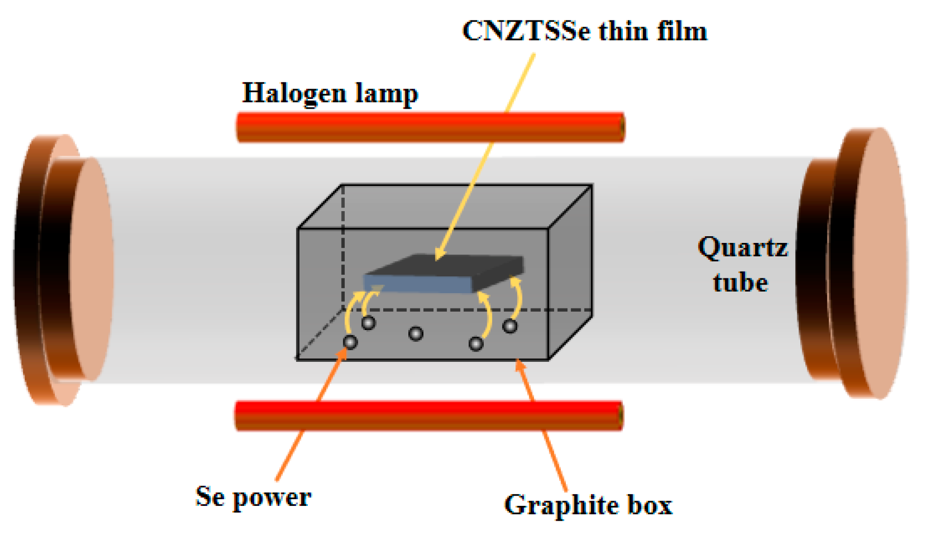
Figure 1. Schematics of graphite box used for selenization annealing.
Nanomaterials 12 04311 g001
Figure 2. (a) XRD patterns of CNZTSSe films selenized at various selenidation times; (b) Enlarged images of (112) peaks of CNZTSSe films selenized at various selenidation times.
Nanomaterials 12 04311 g002
Figure 3. Curves of the 2θ, peak intensity, and FWHM of (112) peaks for the CNZTSSe films with the selenization time.
Nanomaterials 12 04311 g003
Figure 4. (a) Cell structure diagram of CNZTSSe film; (b) Lattice parameters a and c of CNZTSSe films obtained at the selenization time of 10, 15, and 20 min; (c) Unit cell volume (V) and η = c/2a of CNZTSSe thin films obtained at the selenization time of 10, 15 and 20 min.
Nanomaterials 12 04311 g004
Figure 5. (a) Raman spectra of CNZTSSe films obtained at various selenization times; (b) Variation curve of various vibration mode peaks with selenization time; (c) Variation curve of main Raman vibration mode A (1) with selenization time.
Nanomaterials 12 04311 g005
Figure 6. XPS spectra of CNZTSSe films selenized at 15 min: (a) Cu 2p, (b) Sn 3d, (c) Zn 2p, (d) S 2p, (e) Se 3d and (f) Ni 2p.
Nanomaterials 12 04311 g006
Figure 7. Surface morphology of the CNZTSSe thin films selenized at 10 min (a), 15 min (b), and 20 min (c).
Nanomaterials 12 04311 g007
Figure 8. The curve of (αhυ)2 vs hυ for CNZTSSe films selenized at 10 min, 15 min, and 20 min; The insert shows the variation curve of Eg with selenidation time.
Nanomaterials 12 04311 g008
Figure 9. (a) J-V characteristic curves of CNZTSSe solar cells at the selenidation time of 10, 15, and 20 min. (b) Corresponding EQE curves of CNZTSSe solar cells.
Nanomaterials 12 04311 g009
Figure 10. Variation curve of main device parameters as selenidation time.
Nanomaterials 12 04311 g010
Table 1. EDS results of the CNZTSSe films at selenidation times of 10 min, 15 min, and 20 min.
SampleCu(% at)Ni(% at)Zn(% at)Sn(% at)S(% at)Se(% at)Cu/(Zn + Ni + Sn)(Ni + Zn)/Sn
10 min23.650.4117.2810.411.7846.470.841.69
15 min23.580.4017.1010.241.7446.950.851.70
20 min22.670.4217.3210.601.7147.290.801.67
Table 2. The resistivity (Ω·cm), carrier concentration (cm−3), and mobility (cm2v−1s−1) of CNZTSSe films were obtained as the selenidation time of 10 min, 15 min, and 20 min.
SamplesResistivity (Ω·cm)Carrier Concentration (cm−3)Mobility (cm2V−1s−1)Type
10 min1.51 × 1021.21 × 10163.39p
15 min9.98 × 1011.68 × 10163.78p
20 min1.75 × 1021.66 × 10162.12p
Table 3. The main photovoltaic parameters of CNZTSSe solar cells were prepared at the selenidation time of 10, 15, and 20 min.
DeviceActive AreaVOC (mV)JSC (mA/cm2)FF (%)PCE (%)Rs (Ω cm2)Rsh (Ω cm2)
CNZTSSe (T = 10 min)0.19 cm230929.9439.463.62.58186.01
CNZTSSe (T = 15 min)0.19 cm233733.6144.155.01.86253.05
CNZTSSe (T = 20 min)0.19 cm233331.1542.864.42.01212.96
Publisher’s Note: MDPI stays neutral with regard to jurisdictional claims in published maps and institutional affiliations.