
Microstructure and Superior Corrosion Resistance of an In-Situ Synthesized NiTi-Based Intermetallic Coating via Laser Melting Deposition

 , ,
, ,
Abstract
:1. Introduction
2. Materials and Methods
2.1. Materials
2.2. LMD Coating Process
3. Results and Discussion
3.1. Microstructure of the NiTi-Based Intermetallic Coating
3.2. Microhardness of NiTi-Based Intermetallic Coating
3.3. Electrochemical Corrosion of the NiTi-Based Intermetallic Coating
4. Conclusions
- (1)
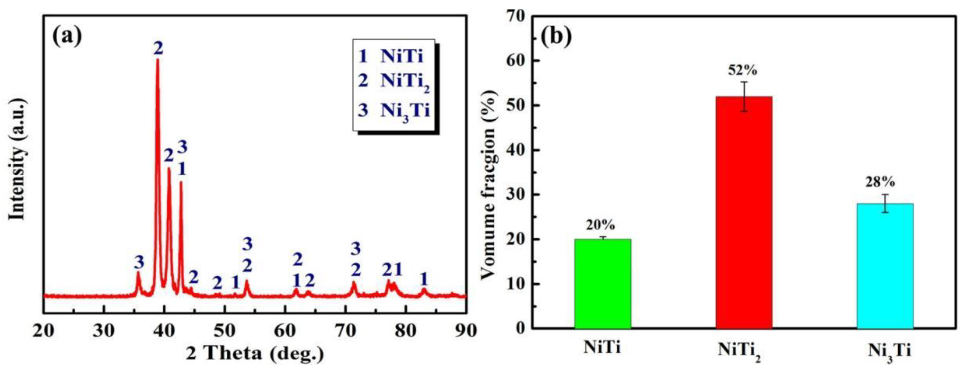
- The NiTi-based intermetallic coating was in-situ synthesized on the TC4 substrate by LMD using a mixed powder of Ni-20Cr and TC4. The phases of the coating are composed of the intermetallic compounds of NiTi2, NiTi, and Ni3Ti, and their volume fractions are ~52%, ~20% and ~28%, respectively.
- (2)
- The microhardness of the intermetallic coating is ~850 HV0.2, which is ~2.5 times larger than that of the TC4 alloy. The high microhardness can be attributed to the solid solution strengthening of Al and Cr, dispersion strengthening of the intermetallic compounds, and grain refinement strengthening from the rapid solidification.
- (3)
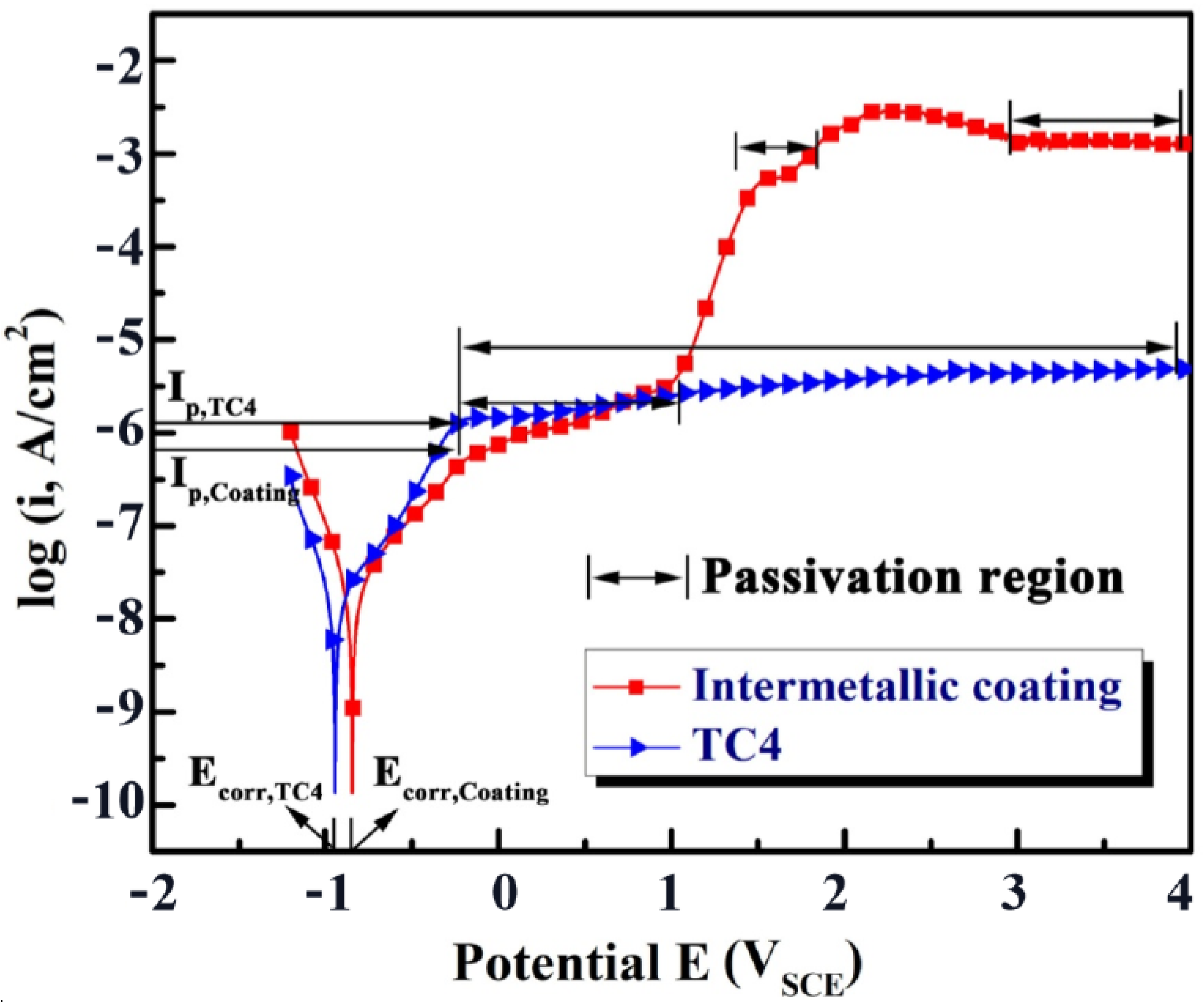
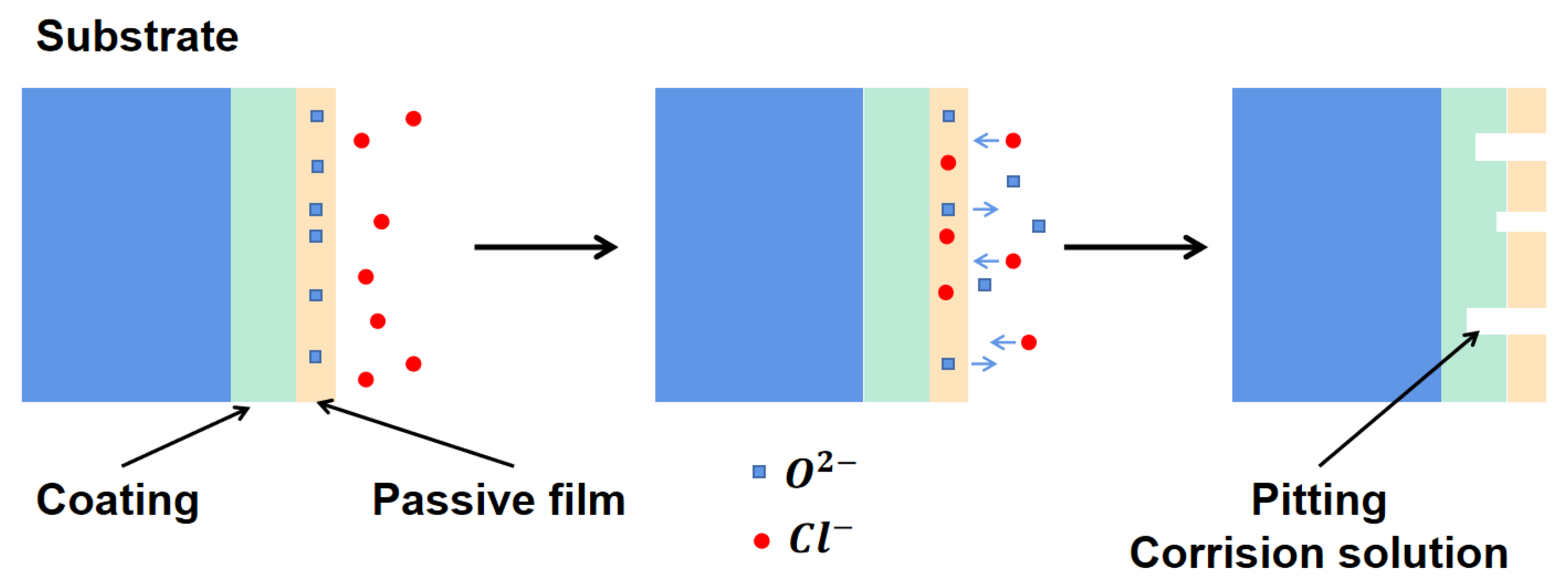
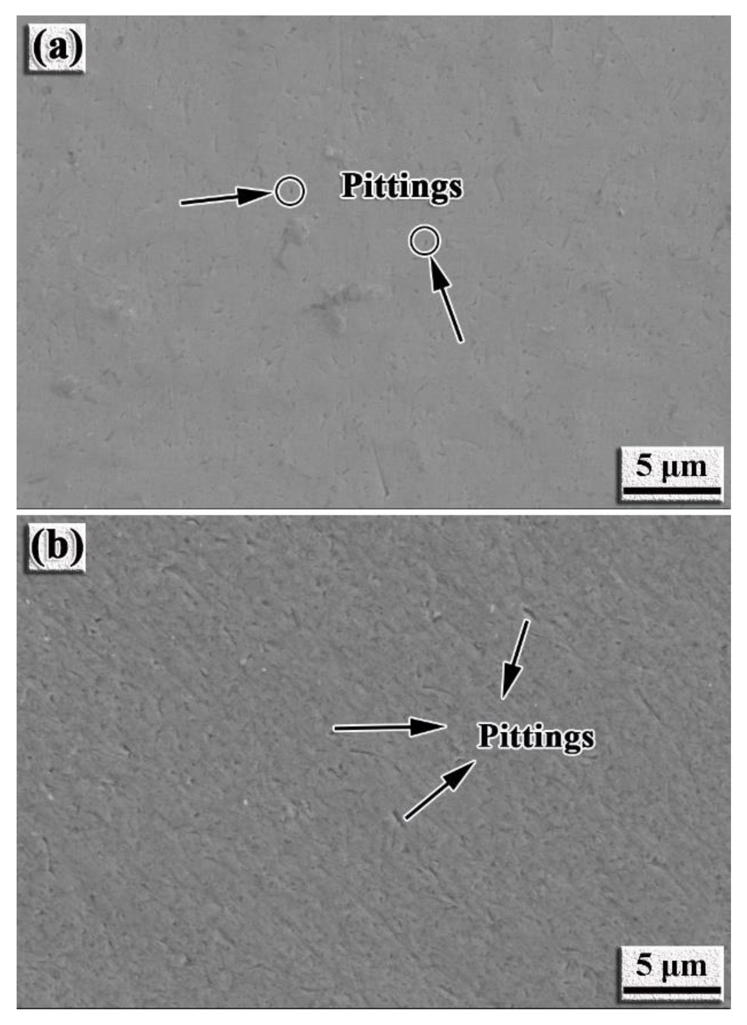
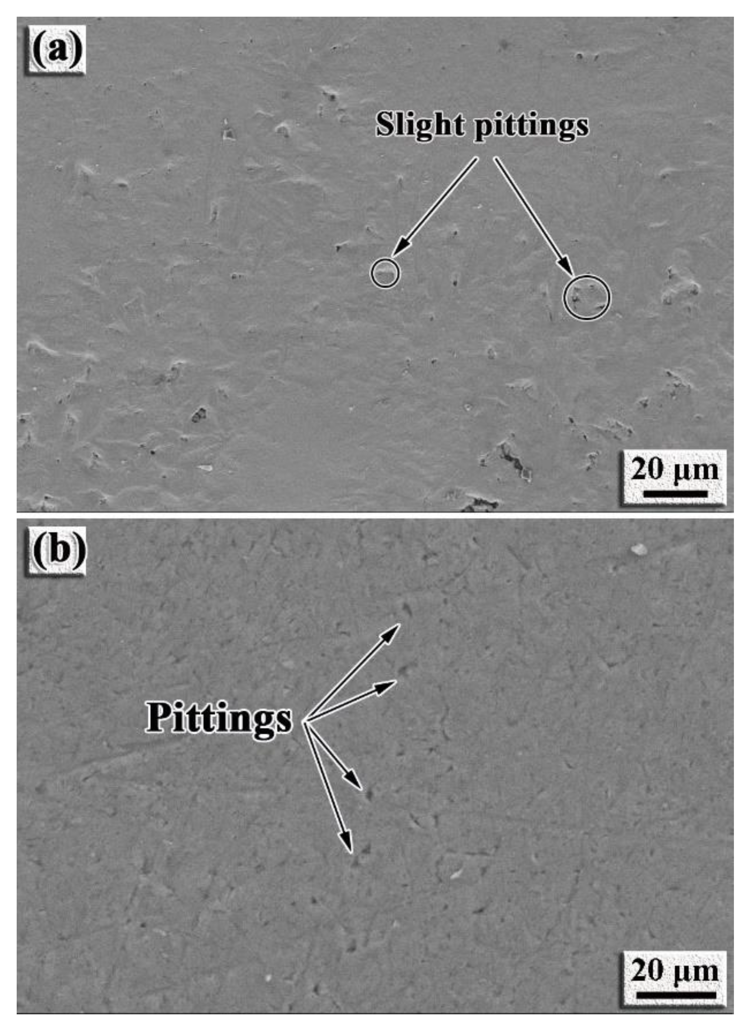
- The intermetallic coating exhibits better corrosion resistance than the TC4 alloy. With the increase in the corrosion voltage, a large amount of Ti ions react with the Cl− ions to form [TiCl6]2− in the solution. When [TiCl6]2− reaches a certain critical value, TiO2 is formed by hydrolysis reaction to protect the intermetallic coating from further corrosion. Slight pitting appears on the coating surface, while large pits can be observed on the TC4 surface.
Author Contributions
Funding
Data Availability Statement
Conflicts of Interest
References
- Gao, F.; Wang, H.M. Effect of TiNi in dry sliding wear of laser melt deposited Ti2Ni/TiNi alloys. Mater. Charact. 2008, 59, 1349–1354. [Google Scholar] [CrossRef]
- Wang, L.; Xie, L.; Zhang, L.C.; Chen, L.; Ding, Z.; Lv, Y.; Zhang, W.; Lu, W.; Zhang, D. Microstructure evolution and superelasticity of layer-like NiTiNb porous metal prepared by eutectic reaction. Acta Mater. 2018, 143, 214–226. [Google Scholar] [CrossRef]
- Wang, D.; Liu, L.Q.; Deng, G.W.; Deng, C.; Bai, Y.C.; Yang, Y.Q.; Wu, W.H.; Chen, J.; Liu, Y.; Wang, Y.G.; et al. Recent progress on additive manufacturing of multi-material structures with laser powder bed fusion. Virtual Phys. Prototyp. 2022. [Google Scholar] [CrossRef]
- Li, D.Y. Development of novel wear-resistant materials: TiNi-based pseudoelastic tribomaterials. Mater. Des. 2000, 21, 551–555. [Google Scholar] [CrossRef]
- Alves, V.A.; Reis, R.Q.; Santos, I.C.B.; Souza, D.G.; Goncalves, T.d.; Pereira-da-Silva, M.A.; Rossi, A.; da Silva, L.A. In situ impedance spectroscopy study of the electrochemical corrosion of Ti and Ti–6Al–4V in simulated body fluid at 25 °C and 37 °C. Corros. Sci. 2009, 51, 2473–2482. [Google Scholar] [CrossRef]
- Lu, H.Z.; Ma, H.W.; Cai, W.S.; Luo, X.; Wang, Z.; Song, C.H.; Yin, S.; Yang, C. Stable tensile recovery strain induced by a Ni4Ti3 nanoprecipitate in a Ni50.4Ti49.6 shape memory alloy fabricated via selective laser melting. Acta Mater. 2021, 219, 117261. [Google Scholar] [CrossRef]
- Xue, L.; Atli, K.C.; Picak, S.; Zhang, C.; Zhang, B.; Elwany, A.; Arroyave, R.; Karaman, I. Controlling martensitic transformation characteristics in defect-free NiTi shape memory alloys fabricated using laser powder bed fusion and a process optimization framework. Acta Mater. 2021, 215, 117017. [Google Scholar] [CrossRef]
- Zhou, Y.L.; Niinomi, M.; Akahori, T.; Fukui, H.; Toda, H. Corrosion resistance and biocompatibility of Ti–Ta alloys for biomedical applications. Mater. Sci. Eng. A 2005, 398, 28–36. [Google Scholar] [CrossRef]
- Yu, F.; Addison, O.; Baker, S.J.; Davenport, A.J. Lipopolysaccharide inhibits or accelerates biomedical titanium corrosion depending on environmental acidity. Int. J. Oral Sci. 2015, 7, 179–186. [Google Scholar] [CrossRef]
- Hu, L.F.; Li, J.; Tao, Y.F.; Lv, Y.H. Corrosion behaviors of TiNi/NiTi2 matrix coatings in the environment rich in Cl ions. Surf. Coat. Technol. 2017, 311, 295–306. [Google Scholar] [CrossRef]
- Man, H.C.; Cui, Z.D.; Yue, T.M. Corrosion properties of laser surface melted NiTi shape memory alloy. Scr. Mater. 2001, 45, 1447–1453. [Google Scholar] [CrossRef]
- Zhou, K.S.; Wang, D.Z.; Liu, M. A study of the cavitation erosion behavior of a Ti-Ni alloy coating. Surf. Coat. Technol. 1987, 34, 79–87. [Google Scholar] [CrossRef]
- Bitzer, M.; Rauhut, N.; Mauer, G.; Bram, M.; Vaben, R.; Buchkremer, H.P.; Stover, D.; Pohl, M. Cavitation-resistant NiTi coatings produced by low-pressure plasma spraying (LPPS). Wear 2015, 328–329, 369–377. [Google Scholar] [CrossRef]
- Hiraga, H.; Inoue, T.; Shimura, H.; Matsunawa, A. Cavitation erosion mechanism of NiTi coatings made by laser plasma hybrid spraying. Wear 1999, 231, 272–278. [Google Scholar] [CrossRef]
- Hiraga, H.; Inoue, T.; Kamado, S.; Kojima, Y.; Matsunawa, A.; Shimura, H. Fabrication of NiTi intermetallic compound coating made by laser plasma hybrid spraying of mechanically alloyed powders. Surf. Coat. Technol. 2001, 139, 93–100. [Google Scholar] [CrossRef]
- Cui, Z.D.; Man, H.C.; Cheng, F.T.; Yue, T.M. Cavitation erosion–corrosion characteristics of laser surface modified NiTi shape memory alloy. Surf. Coat. Technol. 2003, 162, 147–153. [Google Scholar] [CrossRef]
- Zhang, H.; Zhang, C.H.; Wang, Q.; Wu, C.L.; Zhang, S.; Chen, J.; Abdullah, A.O. Effect of Ni content on stainless steel fabricated by laser melting deposition. Opt. Lasers Technol. 2018, 101, 363–371. [Google Scholar] [CrossRef]
- Li, B.; Han, C.; Lim, C.; Zhou, K. Interface formation and deformation behaviors of an additively manufactured nickel-aluminum-bronze/15-5 PH multimaterial via laser-powder directed energy deposition. Mater. Sci. Eng. A 2022, 829, 142101–142115. [Google Scholar] [CrossRef]
- Mostafa, A.M.; Menazea, A.A. Laser-assisted for preparation ZnO/CdO thin film prepared by pulsed laser deposition for catalytic degradation. Radiat. Phys. Chem. 2020, 176, 109020. [Google Scholar] [CrossRef]
- Gao, F.; Wang, H. Abrasion wear property of laser melting/deposition Ti2Ni/TiNi intermetallic alloy. Trans. Nonferrous Met. Soc. China 2007, 17, 1358–1362. [Google Scholar] [CrossRef]
- Suryanarayana, C. Mechanical alloying and milling. Prog. Mater. Sci. 2001, 46, 1–184. [Google Scholar] [CrossRef]
- Ehtemam-Haghighi, S.; Liu, Y.; Cao, G.; Zhang, L.C. Phase transition, microstructure evolution and mechanical properties of Ti-Nb-Fe alloys induced by Fe addition. Mater. Des. 2016, 97, 279–286. [Google Scholar] [CrossRef]
- Zhang, L.C.; Shen, Z.Q.; Xu, J. Glass formation in a (Ti,Zr,Hf)-(Cu,Ni,Ag)-Al high-order alloy system by mechanical alloying. J. Mater. Res. 2003, 18, 2141–2149. [Google Scholar] [CrossRef] [Green Version]
- Zhou, S.; Zeng, X. Growth characteristics and mechanism of carbides precipitation in WC-Fe composite coatings by laser induction hybrid rapid cladding. J. Alloys Compd. 2010, 505, 685–691. [Google Scholar] [CrossRef]
- Zhou, S.; Xiong, Z.; Dai, X.; Liu, J.; Zhang, T.; Wang, C. Microstructure and oxidation resistance of cryomilled NiCrAlY coating by laser induction hybrid rapid cladding. Surf. Coat. Technol. 2014, 258, 943–949. [Google Scholar] [CrossRef]
- Gremaud, M.; Carrard, M.; Kurz, W. The microstructure of rapidly solidifed Al-Fe alloys subjected to laser surface treatment. Acta Metall. Mater. 1990, 38, 1587–1599. [Google Scholar] [CrossRef]
- Zhong, M.; Liu, W.; Yao, K.; Goussain, J.C.; Mayer, C.; Becker, A. Microstructural evolution in high power laser cladding of Stellite 6+WC layers. Surf. Coat. Technol. 2002, 157, 128–137. [Google Scholar] [CrossRef]
- Garay, J.E.; Anselmi-Tamburini, U.; Munir, Z.A. Enhanced growth of intermetallic phases in the Ni-Ti system by current effects. Acta Mater. 2003, 51, 4487–4495. [Google Scholar] [CrossRef]
- Nagarajan, R.; Chattopadhyay, K. Intermetallic Ti2Ni/TiNi nanocomposite by rapid solidification. Acta Metall. Mater. 1994, 42, 947–958. [Google Scholar] [CrossRef]
- Liu, F.; Mao, Y.; Lin, X.; Zhou, B.; Qian, T. Microstructure and high temperature oxidation resistance of Ti-Ni gradient coating on TA2 titanium alloy fabricated by laser cladding. Opt. Laser Technol. 2016, 83, 140–147. [Google Scholar] [CrossRef]
- Locci, A.M.; Orrù, R.; Cao, G.; Munir, Z.A. Field-activated pressure-assisted synthesis of NiTi. Intermetallics 2003, 11, 555–571. [Google Scholar] [CrossRef]
- Li, B.Y.; Rong, L.J.; Li, Y.Y. Stress–strain behavior of porous Ni–Ti shape memory intermetallics synthesized from powder sintering. Intermetallics 2000, 8, 643–646. [Google Scholar] [CrossRef]
- Neves, F.; Martins, I.; Correia, J.B.; Oliveira, M.; Gaffet, E. Reactive extrusion synthesis of mechanically activated Ti–50Ni powders. Intermetallics 2007, 15, 1623–1631. [Google Scholar] [CrossRef]
- Guilemany, J.M.; Cinca, N.; Dosta, S.; Benedetti, A.V. Corrosion behaviour of thermal sprayed nitinol coatings. Corros. Sci. 2009, 51, 171–180. [Google Scholar] [CrossRef]
- Dai, N.; Zhang, L.C.; Zhang, J.; Chen, Q.; Wu, M. Corrosion behavior of selective laser melted Ti-6Al-4V alloy in NaCl solution. Corros. Sci. 2016, 102, 484–489. [Google Scholar] [CrossRef]
- Dai, N.; Zhang, L.C.; Zhang, J.; Zhang, X.; Ni, Q.; Cheng, Y.; Wu, M.; Yang, C. Distinction in corrosion resistance of selective laser melted Ti-6Al-4V alloy on different planes. Corros. Sci. 2016, 111, 703–710. [Google Scholar] [CrossRef] [Green Version]
- Chen, Y.; Zhang, J.; Dai, N.; Qin, P.; Attar, H.; Zhang, L.C. Corrosion behavior of selective laser melted Ti-TiB biocomposite in simulated body fluid. Electrochim. Acta 2017, 232, 89–97. [Google Scholar] [CrossRef] [Green Version]
- Chen, Y.; Zhang, J.; Gu, X.; Dai, N.; Qin, P.; Zhang, L.C. Distinction of corrosion resistance of selective laser melted Al-12Si alloy on different planes. J. Alloys Compd. 2018, 747, 648–658. [Google Scholar] [CrossRef]
- Jia, Z.; Duan, X.; Qin, P.; Zhang, W.; Wang, W.; Yang, C.; Sun, H.; Wang, S.; Zhang, L.C. Disordered atomic packing structure of metallic glass: Toward ultrafast hydroxyl radicals production rate and strong electron transfer ability in catalytic performance. Adv. Funct. Mater. 2017, 27, 1702258. [Google Scholar] [CrossRef]
- Dai, N.; Zhang, J.; Chen, Y.; Zhang, L.C. Heat treatment degrading the corrosion resistance of selective laser melted Ti-6Al-V alloy. J. Electrochem. Soc. 2017, 164, C428–C434. [Google Scholar] [CrossRef]
- Handzlik, P.; Fitzner, K. Corrosion resistance of Ti and Ti–Pd alloy in phosphate buffered saline solutions with and without H2O2, addition. Trans. Nonferrous Met. Soc. China 2013, 23, 866–875. [Google Scholar] [CrossRef]
- Obadele, B.A.; Olubambi, P.A.; Andrews, A.; Pityana, S.; Mathew, M.T. Electrochemical behaviour of laser-clad Ti6Al4V with CP Ti in 0.1 M oxalic acid solution. J. Alloys Compd. 2015, 646, 753–759. [Google Scholar] [CrossRef]
- Verdian, M.M.; Raeissi, K.; Salehi, M. Corrosion performance of HVOF and APS thermally sprayed NiTi intermetallic coatings in 3.5% NaCl solution. Corros. Sci. 2010, 52, 1052–1059. [Google Scholar] [CrossRef]
- González, J.E.G.; Mirza-Rosca, J.C. Study of the corrosion behavior of titanium and some of its alloys for biomedical and dental implant applications. J. Electroanal. Chem. 1999, 471, 109–115. [Google Scholar] [CrossRef]


| Element | C | H | O | N | Fe | Al | V | Ti |
|---|---|---|---|---|---|---|---|---|
| Composition (wt%) | 0.08 | 0.015 | 0.2 | 0.05 | 0.4 | 6.05 | 4.02 | Bal. |
| Location | Composition (wt%) | ||||
|---|---|---|---|---|---|
| Al | Ti | V | Cr | Ni | |
| A | 2.98 | 44.33 | 1.63 | 8.01 | 43.01 |
| B | 3.93 | 56.61 | 1.87 | 4.93 | 32.66 |
| C | 3.59 | 56.79 | 1.61 | 6.86 | 31.16 |
| D | 4.1 | 47.27 | 4.27 | 16.95 | 27.41 |
| E | 1.84 | 58.99 | 1.48 | 3.42 | 34.27 |
| F | 5.14 | 56.86 | 1.49 | 3.89 | 32.62 |
| Sample | Ecorr (V) | Icorr (A/cm2) | Ip (A/cm2) |
|---|---|---|---|
| Immiscible coating | −0.854 | 1.977 × 10⁻⁷ | −6.2 ± 0.01 |
| TC4 alloy | −0.943 | 2.068 × 10⁻⁷ | −5.8 ± 0.01 |
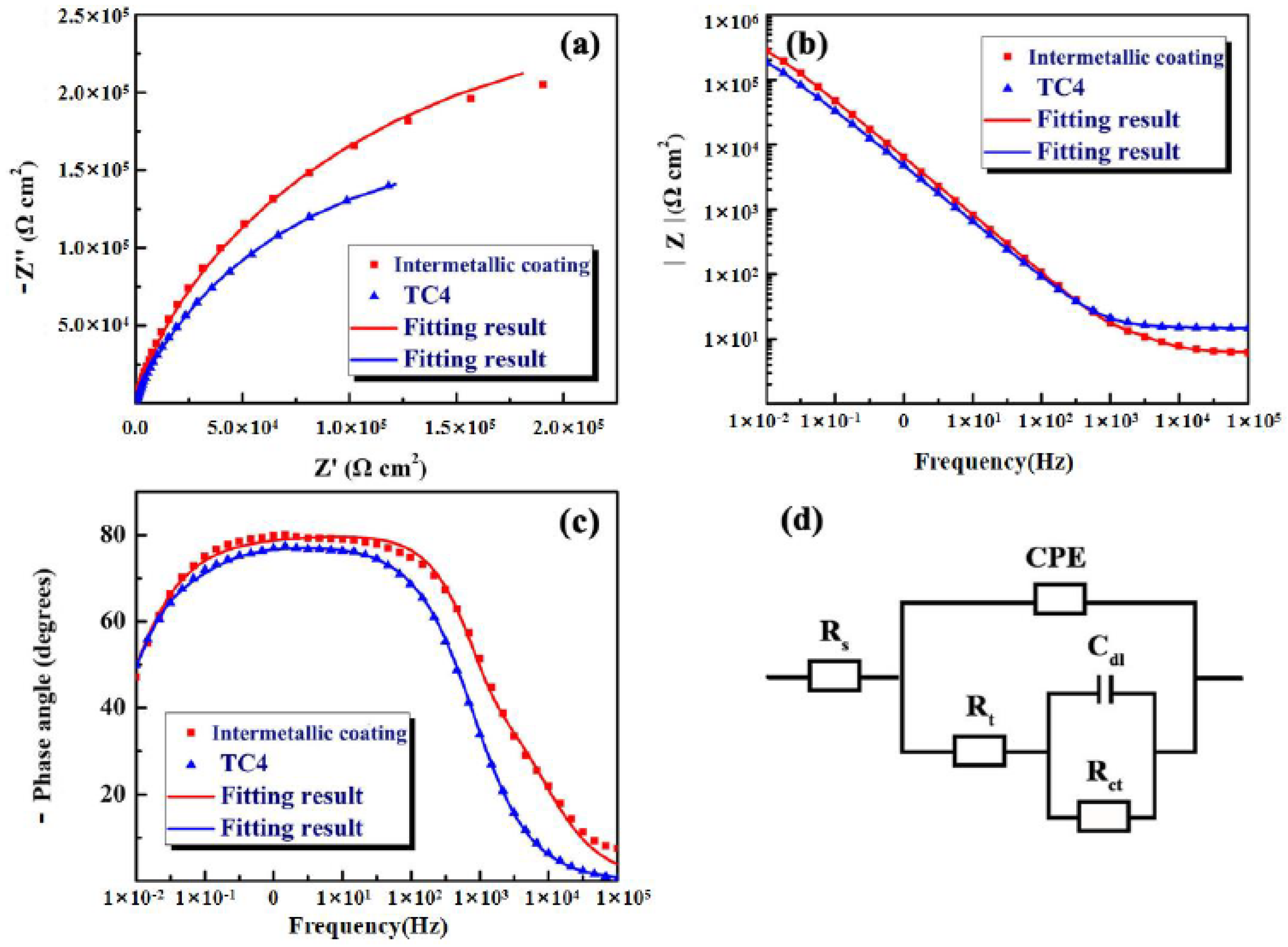
| Sample | RS (Ω cm2) | Rt (Ω cm2) | Rct (Ω cm2) | Cd1 (F cm−2) | Q1-Y0 (Ω−1 cm2sn) | n1 | χ2 |
|---|---|---|---|---|---|---|---|
| NiTi-based coating | 6.931 | 23.99 | 5.69 × 10⁵ | 4.94 × 10⁻⁶ | 2.63 × 10⁻⁵ | 0.8628 | 8.6 × 10⁻⁴ |
| TC4 alloy | 14.82 | 2.459 × 10⁵ | 1.33 × 10⁵ | 3.27 × 10⁻⁵ | 4.29 × 10⁻⁵ | 0.8548 | 1.2 × 10⁻⁴ |
Publisher’s Note: MDPI stays neutral with regard to jurisdictional claims in published maps and institutional affiliations. |
© 2022 by the authors. Licensee MDPI, Basel, Switzerland. This article is an open access article distributed under the terms and conditions of the Creative Commons Attribution (CC BY) license (https://creativecommons.org/licenses/by/4.0/).
Share and Cite
Deng, C.; Jiang, M.; Wang, D.; Yang, Y.; Trofimov, V.; Hu, L.; Han, C. Microstructure and Superior Corrosion Resistance of an In-Situ Synthesized NiTi-Based Intermetallic Coating via Laser Melting Deposition. Nanomaterials 2022, 12, 705. https://doi.org/10.3390/nano12040705
Deng C, Jiang M, Wang D, Yang Y, Trofimov V, Hu L, Han C. Microstructure and Superior Corrosion Resistance of an In-Situ Synthesized NiTi-Based Intermetallic Coating via Laser Melting Deposition. Nanomaterials. 2022; 12(4):705. https://doi.org/10.3390/nano12040705
Chicago/Turabian StyleDeng, Cheng, Menglong Jiang, Di Wang, Yongqiang Yang, Vyacheslav Trofimov, Lianxi Hu, and Changjun Han. 2022. "Microstructure and Superior Corrosion Resistance of an In-Situ Synthesized NiTi-Based Intermetallic Coating via Laser Melting Deposition" Nanomaterials 12, no. 4: 705. https://doi.org/10.3390/nano12040705