Abstract
The concept of nanoparticle-mediated electron transfer (eT) across insulating thin films was elucidated theoretically by Allongue and Chazalviel in 2011. In their model, metal nanoparticles (NPs) are immobilized atop passivating, self-assembled monolayers (SAMs). They found that under certain conditions, related to the thickness of the SAM and the size of the NPs, efficient faradaic oxidation and reduction reactions could proceed at the NP surface. In the absence of NPs, however, eT was suppressed by the insulating SAM thin films. Allongue and Chazalviel concluded that, within certain bounds, eT is mediated by fast tunneling between the conductive electrode and the metal NPs, while the kinetics of the redox reaction are controlled by the NPs. This understanding has been confirmed using a variety of experimental models. The theory is based on electron tunneling; therefore, the nature of the intervening medium (the insulator in prior studies) should not affect the eT rate. In the present manuscript, however, we show that the theory breaks down under certain electrochemical conditions when the medium between conductors is an n-type semiconductor. Specifically, we find that in the presence of either Au or Pt NPs immobilized on a thin film of TiOx, CO electrooxidation does not proceed. In contrast, the exact same systems lead to the efficient reduction of oxygen. At present, we are unable to explain this finding within the context of the model of Allongue and Chazalviel.
1. Introduction
The concept of nanoparticle-mediated electron transfer (eT) across insulating thin films was elucidated theoretically by Allongue and Chazalviel in 2011 [1]. In their model, metal nanoparticles (NPs) are immobilized atop passivating, self-assembled monolayers (SAMs) (Scheme 1a). They found that under certain conditions, related to the thickness of the SAM and the size of the NPs, efficient faradaic oxidation and reduction reactions could proceed at the NP surface. In the absence of the NPs, however, eT was suppressed by the insulating SAM thin films. Allongue and Chazalviel concluded that, within certain bounds, eT is mediated by fast tunneling between the conductive electrode and the metal NPs, while the kinetics of the redox reaction are controlled by the NPs.
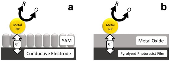
Scheme 1.
NP-mediated eT across insulating (a) SAM and (b) metal oxide thin films.
The foregoing theoretical findings were subsequently confirmed and expanded upon experimentally by Gooding and Paddon-Row, and Fermin [2,3]. Specifically, Fermin demonstrated long-distance electronic communication between AuNPs and SAM-modified Au electrode using Fe(CN)63−/4− as a redox probe [2]. Similarly, Gooding, Paddon-Row, and co-workers studied the electrochemical response of Ru(NH3)63+/2+ at Au electrodes modified with an SAM layer in the presence and absence of AuNPs [3]. Just as predicted by Allongue and Chazalviel, they found a suppression of faradaic current in the absence of the AuNPs, but full recovery when AuNPs were present on the surface of the SAM.
Most reports of NP-mediated eT have involved reversible redox couples such as Ru(NH3)63+/2+ or Fe(CN)63−/4− at either SAM- or polymer-modified electrodes [4,5,6]. In contrast, our group has been studying electrocatalytic reactions at electrodes passivated with thin oxide layers modified with either PtNPs [7,8] or AuNPs [9,10]. This configuration is illustrated in Scheme 1b. In this case, the underlying electrode is a pyrolyzed photoresist film (PPF) [11] and the thin oxide layers are produced using atomic layer deposition (ALD). The purpose of these investigations has been to systematically study how strong metal–support interactions (SMSIs) affect electrocatalytic reactions.
In our first study, we validated the model shown in Scheme 1b using Al2O3, a metal oxide that does not engender SMSI [7,8]. Specifically, we tested the electrochemical activity of a construct we denote as PPF/Al2O3(2.5 nm)/PtNP, where 2.5 nm is the thickness of the intermediate oxide film. We examined both the reversible redox molecule Fc(MeOH)2 and the oxygen reduction reaction (ORR) at this interface. Importantly, the results showed that this experimental model system closely follows the theoretical model described by Allongue and Chazalviel for both reactions. Furthermore, we confirmed that Al2O3 has no effect on the ORR activity of the supported PtNPs.
In contrast to our study of Al2O3, we reported on a synergistic relationship between AuNPs and TiOx (2.8 nm thick, x = 1.9; and 2.0) supports towards the ORR [10]. Specifically, we observed a reproducible ~100 mV positive shift in the onset potential, and an increase in the effective number of electrons transferred during the ORR, at TiOx-supported AuNPs compared with AuNPs in the absence of support effects. Importantly, these results were found to be in quantitative agreement with density functional theory (DFT) calculations. In this study, the theoretical calculations were carried out using just one descriptor: the binding energy of the adsorbed OH intermediate (OH*). The results showed that a synergetic relationship exists between AuNPs and the TiOx support due to a partial charge transfer from oxygen vacancies in the TiOx to the AuNPs. This change in charge distribution is responsible for optimizing the OH* binding energy on the AuNPs; hence, the ORR enhancement. Experimentally, X-ray photoelectron spectroscopy (XPS) confirmed the presence of increased electron density on the AuNPs when they were in direct contact with the TiOx support. This successful collaboration between theory and experiment encouraged us to apply our model to a more complex reaction.
Following the ORR study, we wished to expand the complexity of the DFT calculations to include a reaction requiring two descriptors and then verify the degree of theoretical efficacy. Preliminary calculations suggested that the CO electrooxidation reaction would be a good target, because its activity at AuNPs supported on TiOx thin films is predicted to increase. Accordingly, we constructed a model system similar to that used for the foregoing ORR study. The results presented herein are surprising (but reproducible and consistent). Specifically, we observed little or no activity for CO electrooxidation. Detailed control experiments indicate the reason for this is that electrons are unable to tunnel through the TiOx layer at positive potentials. This finding calls into question the universality of the experimental model shown in Scheme 1.
2. Materials and Methods
2.1. Chemicals and Materials
The following chemicals were used as received: [Ru(NH3)6]Cl3 (98%,Acros Organics, Morris Plains, NJ, USA); 1,1′-ferrocenedimethanol (Fc(MeOH)2, 98%, Acros Organics, Morris Plains, NJ, USA); KNO3 (certified, Fisher Scientific, Waltham, MA, USA); NaOH (1 M, Fisher Scientific, Waltham, MA, USA); HClO4 (+70%, ultrapure grade, J. T. Baker, Phillipsburg, NJ, USA); o-H3PO4 (85%, certified ACS, Fisher Scientific, Waltham, MA, USA); KH2PO4, K2HPO4, K3PO4 (certified, Fisher Scientific, Waltham, MA, USA); NaBH4 (99.99% trace metals basis, Sigma-Aldrich, Saint Louis, MO, USA); CuSO4 (98%, pure, anhydrous, Acros Organics, Morris Plains, NJ, USA); HAuCl4·3H2O (99.9% trace metals basis, Sigma-Aldrich, Saint Louis, MO, USA); K2PtCl4 (99.99% trace metals basis, Acros Organics, Morris Plains, NJ, USA), tetrakis(dimethylamino)titanium (IV) (TDMAT, 99%, STREM Chemicals, Inc., Newburyport, MA, USA), and trimethylaluminum (TMA, 98%, STREM Chemicals, Inc., Newburyport, MA, USA). The following compressed gases were purchased from Praxair (Austin, TX, USA): high-purity CO (99.5%), high-purity O2 (99.995%), high-purity Ar (99.998%), and forming gas (5% H2/95% N2).
Sixth-generation, amine-terminated (G6NH2) and hydroxy-terminated (G6OH) poly(amidoamine) dendrimers were purchased as 9.00 wt% and 12.98 wt% methanol solutions, respectively, from Dendritech, Inc. (Midland, MI, USA). For the dendrimer-encapsulated NP (DEN) synthesis, methanol was removed from the stock solution under vacuum and the dendrimers were reconstituted in water. UHPLC-grade water from Sigma-Aldrich (Saint Louis, MO, USA) was used to reconstitute the dendrimers, to synthesize DENs, and to prepare all aqueous solutions.
For PPF fabrication, fused quartz slides (GE 124, 3” × 1” × 1 mm) were purchased from Technical Glass Products, Inc. (Painesville Township, OH, USA), photoresist (AZ 1518), and photoresist developer (AZ 400 K, 1:4) were purchased from Integrated Micro Materials (Argyle, TX, USA).
2.2. Fabrication of Pyrolyzed Photoresist Film (PPF) Electrodes
PPF electrodes were fabricated by following a previously reported procedure that can be found elsewhere [10].
2.3. Deposition of ALD Thin Films on PPF Electrodes
The metal oxide thin films, TiOx (x = 1.9; and 2.0) and Al2O3, were deposited using previously reported procedures [7,10]. Additional details can be found in the Supplementary Materials.
2.4. Synthesis and Immobilization of Au DENs
G6NH2(Au147) DENs were synthesized as follows using a previously published direct-reduction procedure [9,10]. First, 200 μL of a 100 μM aqueous G6NH2 dendrimer solution was added to 8.65 mL of vigorously stirred UHPLC water. Second, 147 μL of 20.0 mM HAuCl4 was pipetted dropwise into the diluted dendrimer solution. Third, within 2 min after adding the first drop of the HAuCl4 solution, a ~67-fold molar excess of NaBH4 (in 1.0 mL of 0.30 M NaOH) was added. Then, the reaction mixture was stirred overnight in air to deactivate excess NaBH4. This synthesis has previously been shown to produce AuNPs with an average size of 1.6 ± 0.2 nm (Figure S1 in the Supplementary Materials) [12,13].
Prior to immobilizing the G6NH2(Au147) DENs onto the PPF/TiOx supports, the pH of the DENs solution was adjusted to ~3.2 using 1.0 M HClO4. We previously showed that this adjustment does not alter the size distribution of the AuNPs [10]. The G6NH2(Au147) DENs were immobilized by immersing the PPF/TiOx supports in the DENs solution for 90 min. After immobilization, the modified supports (PPF/TiOx/G6NH2(Au147)) were gently rinsed with UHPLC water and dried under a flow of Ar. The modified supports were further air-dried in the lab for at least 1 h prior to the use.
2.5. Synthesis and Immobilization of Pt DENs
G6OH(Pt55) DENs were prepared as follows using a previously published indirect galvanic exchange method [7]. First, 1.0 mL of 100 μM of an aqueous G6OH dendrimer solution was added to 8.68 mL of moderately stirred UHPLC water. This solution was kept under an Ar atmosphere for the duration of the synthesis. Second, 0.275 mL of 20.0 mM CuSO4 was pipetted dropwise into the diluted dendrimer solution and it was allowed to equilibrate for 15 min. Then, 32.7 μL of 1.0 M NaBH4 was pipetted dropwise into the G6OH-(Cu2+)55 DEN precursor solution, and the reaction mixture was stirred for 50 min. Subsequently, the pH of the solution was adjusted to 3.0 using 1.0 M HClO4. Finally, 0.550 mL of 10.0 mM K2PtCl4 was pipetted dropwise into the G6OH(Cu55) solution. The final reaction mixture was stirred for 60 min to allow complete galvanic exchange between Cu0 and Pt2+ to occur. This synthesis produced PtNPs with an average size of 1.3 ± 0.2 nm (Figure S2 in the Supplementary Materials) [7].
The G6OH(Pt55) DENs were immobilized by immersing the PPF/TiOx or PPF/Al2O3 supports in the DENs solution for 45 min. After the immobilization, the modified supports (PPF/TiOx/G6OH(Pt55) or PPF/Al2O3/G6OH(Pt55)), were rinsed with UHPLC water and dried under flowing Ar. The modified supports were further air-dried in the lab for at least 1 h prior to use.
2.6. UV/O3 Method for Decomposition of G6NH2 and G6OH Dendrimers
We previously reported a procedure for decomposing dendrimers using a UV/O3 process [8,9,10]. The resulting PPF/TiOx/Au147, PPF/TiOx/Pt55, and PPF/Al2O3/Pt55 (Figure S3 in the Supplementary Materials) supports were equilibrated in an ambient atmosphere for at least 45 min before use.
2.7. Structural Characterization
XPS measurements were performed using a Kratos Axis Ultra DLD spectrometer (Chestnut Ridge, NY, USA). The samples were analyzed according to a previous report from our lab [10]. Briefly, the spectra were collected using an Al Kα source, 0.10 eV step size, and 20 eV band pass energy. CasaXPS (version 2.3.19, Casa Software, Teignmouth, UK) was used for peak fitting and quantitative data analysis. Binding energies (BEs) were calibrated using the C 1s line of PPF (284.50 eV) [14,15]. The specific method used for peak fitting and the oxygen vacancy calculation for the TiOx thin films have been described previously [10]. Likewise, electronic interactions between TiOx and Al2O3 thin-film-supported metal NPs have been extensively characterized in our related studies [7,8,9,10].
Ellipsometric thickness measurements were performed using a J. A. Woollam M-2000 D spectroscopic ellipsometer (Lincoln, NE, USA). Data were collected between 45° and 65° with 5° increments and a 10 s dwell time at each step. The specific model that was created for the data analysis has been described previously [10].
Transmission electron microscopy (TEM) images were collected using a JEOL-2010F TEM (JOEL USA Inc., Peabody, MA, USA) having a point-to point resolution of 0.2 nm. For this, 2.0 μL of the DENs solution was pipetted onto a carbon-mesh-over-Cu TEM grid (Electron Microscopy Sciences, Hatfield, PA, USA). The samples were left to dry overnight in the ambient laboratory atmosphere prior to the analysis. We have previously described the topography and the crystallinity of the TiOx and Al2O3, ALD thin films [7,8,10].
2.8. Electrochemical Characterization
A CHI 700E bipotentiostat, a Hg/Hg2SO4 reference electrode, and a glassy carbon rod counter electrode were used for all electrochemical measurements (CH Instruments Inc., Austin, TX, USA). These measurements were performed in a Teflon electrochemical cell which constrained the geometric area of the working electrode to 12.4 mm2 [7].
Prior to the electrocatalytic experiments, the extent of passivation and the stability of the PPF/TiOx and PPF/Al2O3 supports were determined using 1.0 mM Fc(MeOH)2 and 0.10 M KNO3. All electrocatalytic experiments were performed using electrocatalysts from which dendrimer had been removed. Note, however, that there is no significant difference in CO electrooxidation activity on electrocatalysts with and without the dendrimer (Figure S4 in the Supplementary Materials). The high degree of stability of electrocatalysts containing metal NPs, PPF/TiOx/Au147 and PPF/Al2O3/Pt55, have previously been described [7,8,9,10].
Prior to the CO electrooxidation experiments, all modified supports were electrochemically cleaned in an Ar-saturated, 0.10 M HClO4 solution. During the cleaning of the supports with AuNPs on the surface, the electrode potential was scanned ten times between −0.20 and 0.87 V at 0.050 V/s. During the cleaning of the supports with PtNPs on the surface, the electrode potential was scanned ten times between −0.65 and 0.63 V at 0.050 V/s.
Following electrochemical cleaning, CO electrooxidation using the supports with AuNPs on the surface was performed in a CO-saturated, 0.10 M NaOH solution. CO electrooxidation on the supports with PtNPs on the surface were performed in a CO-saturated, 0.10 M HClO4 solution.
The rectifying behavior of the PPF/TiOx supports was studied using 1.0 mM [Ru(NH3)6]Cl3 in an Ar-saturated, 0.10 M phosphate-buffered solutions.
3. Results and Discussion
3.1. Properties of TiOx (x = 1.9; and 2.0) Thin Films
Ellipsometry was used to measure the TiOx film thicknesses as a function of the number of ALD cycles performed. The growth rate of the films was 0.060 ± 0.002 nm/cycle with a nucleation delay [16] of 12 ALD cycles. For the experiments discussed here, the TiOx films were deposited using 50 ALD cycles, which is equivalent to ~2.3 nm in total thickness. The degree of PPF electrode passivation of these TiOx (2.3 nm)-coated PPF electrodes was determined using cyclic voltammetry (CV). For these experiments, an aqueous solution containing 1.0 mM Fc(MeOH)2 and 0.10 M KNO3 was used. Figure S5 in the Supplementary Materials compares CVs for PPF-only, PPF/TiO1.9(2.3 nm), and PPF/TiO2.0(2.3 nm) working electrodes. The results indicate near-complete passivation of faradaic electrochemistry for the two PPF/TiOx films, which is consistent with our previous findings [10].
3.2. CO Electrooxidation at PPF-Supported Au147 NPs
Figure 1 shows CVs for PPF-only and PPF/Au147 electrodes in CO-saturated, 0.10 M NaOH. The alkaline environment was chosen for this experiment because AuNPs smaller than 2.5 nm exhibit little to no CO electrooxidation activity in aqueous acidic solutions [17]. The CV for the PPF-only electrode is inactive for CO electrooxidation. In contrast, a complex CV is observed when Au147 NPs are present atop the PPF surface. Specifically, anodic currents are observed in both the forward and reverse scans. This is a consequence of electrocatalyst deactivation at more positive potentials and subsequent reactivation at less positive potentials, as discussed subsequently [17,18,19]. This behavior is consistent with the Langmuir–Hinshelwood mechanism [19].
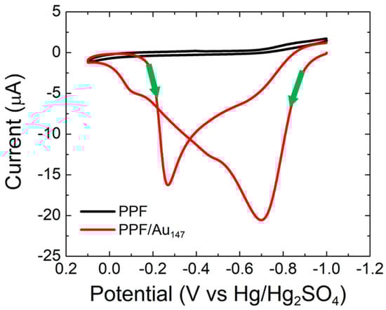
Figure 1.
CVs obtained for CO electrooxidation on bare PPF and PPF/Au147 electrodes. The solutions contained aqueous, CO-saturated 0.10 M NaOH. The electrode potential was scanned between −1.0 and 0.10 V at 0.050 V/s. The experiments were carried out in triplicate for each electrode configuration using independently prepared electrodes to ensure reproducibility.
Focusing on the forward scan of the PPF/Au147 CV, a broad wave corresponding to CO electrooxidation is observed. It consists of a main peak at −0.70 V, and shoulders at −0.47 V and −0.11 V. These three features arise from heterogeneous binding sites on the AuNP electrocatalyst [19]. The maximum CO electrooxidation activity occurs at −0.70 V. As the scan continues, CO is depleted at the electrode surface, and OH* begins to poison the electrocatalyst surface due to increased binding energy (reaching a maximum at 0.10 V) [19].
Upon scan reversal, the OH* binding strength decreases at less positive potentials, thereby making it possible for CO to co-bind to the Au surface. Accordingly, CO electrooxidation continues via the Langmuir–Hinshelwood mechanism. A corresponding broad, reverse wave is present with a main peak at −0.27 V and a shoulder at −0.68 V. The CO electrooxidation current is lower in the reverse direction due to depletion of bulk CO in the vicinity of the electrode surface. Regardless of these details, the key point of this discussion is that the Au147 NPs are active toward CO electrooxidation, and the voltammetry is consistent with literature reports [19].
3.3. CO Electrooxidation at Au147 NPs on TiOx Thin Films
Figure 2a shows CVs for PPF/TiO1.9(2.3 nm) and PPF/TiO1.9(2.3 nm)/Au147 in CO-saturated, 0.10 M NaOH. The CV for the PPF/TiO1.9 electrode reveals the background activity for the TiO1.9 thin film for the same CO electrooxidation conditions reported in the previous section. Specifically, an increase in anodic current is observed at −0.10 V due to the oxygen evolution reaction [20]. No other prominent faradaic activity is detected at PPF/TiO1.9 supports under alkaline conditions.
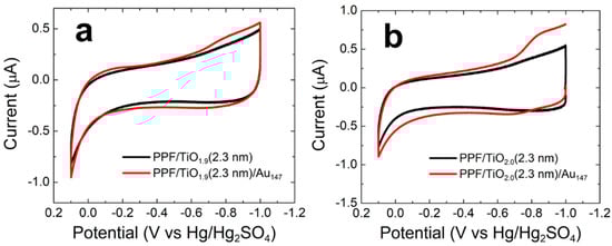
Figure 2.
CVs obtained for CO electrooxidation on (a) PPF/TiO1.9(2.3 nm)/Au147 and (b) PPF/TiO2.0(2.3 nm)/Au147 electrodes. The specific electrode configurations are given in the legends. The solutions contained aqueous, CO-saturated 0.10 M NaOH. The electrode potential was scanned between −1.0 and 0.10 V at 0.050 V/s. The experiments were carried out in triplicate for each electrode configuration using independently prepared electrodes to ensure reproducibility.
Surprisingly, the CV for the PPF/TiO1.9(2.3 nm)/Au147 is almost identical to that of the AuNP-free electrode, indicating little or no CO electrooxidation activity. However, there is a slight increase in cathodic current around −0.8 V in the reverse scan that only appears when Au147 NPs are present. We associate this small peak with the AuNP-catalyzed ORR. No other significant level of faradaic activity is observed.
Figure 2b shows CVs analogous to those discussed above, but for the oxidized TiO2.0(2.3 nm) thin film. The results are consistent with those shown in Figure 2a, with just a slight increase in the ORR current compared with the control experiment, for the PPF/TiO2.0(2.3 nm)/Au147 electrode.
We investigated the possibility of electrocatalyst deactivation under our experimental conditions. Specifically, immediately following the CO electrooxidation measurements, the electrocatalyst used to obtain the data in Figure 2a was tested for ORR activity (Figure S6 in the Supplementary Materials). The results show that significant ORR activity is observed under both acidic and alkaline conditions. Importantly, the ORR onset potential (~0.1 V vs. RHE), which we define as the potential corresponding to 10% of the ORR peak current, matches the value we reported previously [10]. This indicates that the electrocatalyst is stable and does not experience deactivation during CO electrooxidation experiments.
We also studied how the TiOx thin film thickness affects the CO electrooxidation activity of PPF/TiOx/Au147 electrocatalysts (Figure S7 in the Supplementary Materials). The results show that no significant CO electrooxidation activity is observed for TiOx thin films having thicknesses ranging from 1.1 to 2.9 nm.
The foregoing results are puzzling, because they do not follow the current understanding of NP-mediated eT across insulating thin films (Scheme 1). Accordingly, we continued our study by testing whether this surprising behavior is only observed for TiOx/AuNP by investigating CO electrooxidation activity at TiOx/PtNP.
3.4. CO Electrooxidation at PPF-Supported Pt55 NPs
Figure 3 shows CVs for PPF-only and PPF/Pt55 electrodes in CO-saturated, 0.10 M HClO4. We used acidic electrolytes for this experiment, rather than basic electrolytes, for two reasons. First, the CO electrooxidation at Pt catalysts in acidic media has been extensively characterized [21,22,23,24,25]. Second, key experiments involving Al2O3/PtNP supports, which are discussed later, require the use of acidic media due to the instability of Al2O3 in bases [26].
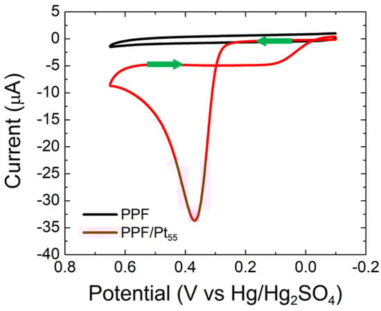
Figure 3.
CVs obtained for CO electrooxidation on bare PPF and PPF/Pt55 electrodes. The solutions contained aqueous, CO-saturated 0.10 M HClO4. The electrode potential was scanned between –0.10 and 0.65 V at 0.050 V/s. The experiments were carried out in triplicate for each electrode configuration using independently prepared electrodes to ensure reproducibility.
The CV for the PPF-only electrode indicates no CO electrooxidation activity for PPF under aqueous acidic conditions. In contrast, well-defined CO electrooxidation activity is present when Pt55 NPs are immobilized atop the PPF surface. Specifically, anodic currents are present in both the forward and reverse scans, with the current in the forward scan being ~10× higher than the reverse scan. This behavior is consistent with the accepted Langmuir–Hinshelwood mechanism for CO electrooxidation at Pt catalysts [21,22,23]. Here, the reactant-pair is CO* and OH*, where OH* originates from water oxidation at the electrode (rather than being present at high concentrations in the electrolyte, as for the AuNP case) [24].
Focusing on the forward scan of the PPF/Pt55 CV, a single peak at 0.37 V, corresponding to CO electrooxidation, is observed. This peak appears broader and is ~200 mV more positive compared with that observed for bulk Pt [21,23,24,25]. This is due to the increased heterogeneity of binding sites, and hence, the CO binding energies, on PtNPs compared with bulk Pt [23]. As the scan continues, the current decreases due to the depletion of CO in the vicinity of the electrode and the surface poisoning effect of an increase in the OH* binding energy at more positive potentials [25].
Upon scan reversal, the electrocatalyst surface is reactivated due to decreased OH* binding energy. However, the depletion of CO near the electrode surface leads to a lower anodic current. The key point of this discussion is that the Pt55 NPs are active toward CO electrooxidation, and the voltammetry is consistent with reports in the literature [21,22,23,24,25].
3.5. CO Electrooxidation at Pt55 NPs on TiOx Thin Films
Figure 4a shows CVs for PPF/TiO1.9(2.3 nm) and PPF/TiO1.9(2.3 nm)/Pt55 in CO-saturated, 0.10 M HClO4. The CV for the PPF/TiO1.9 electrode reveals the background activity for the TiO1.9 thin film for the same CO electrooxidation conditions discussed in the previous section. The results indicate a primarily capacitive current with a slight indication of anodic current at 0.65 V arising from the oxygen evolution reaction [20] and a slight cathodic current at −0.10 V from the hydrogen evolution reaction (HER) [27]. As for the AuNP results, the CV for the PPF/TiO1.9(2.3 nm)/Pt55 is almost identical to that of the PtNP-free electrode, indicating little or no CO electrooxidation activity. Figure 4b shows that CVs analogous to those for the TiO1.9 thin films are very similar when the film is fully oxidized to TiO2.0.
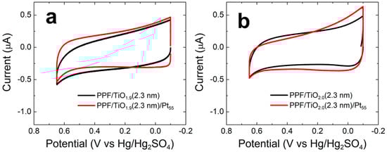
Figure 4.
CVs obtained for CO electrooxidation on (a) PPF/TiO1.9(2.3 nm)/Pt55 and (b) PPF/TiO2.0(2.3 nm)/Pt55 electrodes. The specific electrode configurations are given in the legends. The solutions contained aqueous, CO-saturated 0.10 M HClO4. The electrode potential was scanned between –0.10 and 0.65 V at 0.050 V/s. The experiments were carried out in triplicate for each electrode configuration using independently prepared electrodes to ensure reproducibility.
Comparison of the results for the TiOx/AuNP and TiOx/PtNP thin films suggests that the semiconducting nature of the TiOx films could be responsible for the absence of CO electrooxidation. To test this hypothesis, we replaced TiOx with Al2O3 (a dielectric with a bandgap of ~7 eV) [28] and investigated the resulting Al2O3/PtNP supports for CO electrooxidation. The outcome of these experiments is discussed next.
3.6. Properties of Al2O3 Thin Films
The properties of the Al2O3 thin films used in this part of the study were characterized exactly as for the TiOx thin films. Ellipsometry revealed that the Al2O3 films grew at a rate of 0.081 ± 0.003 nm/cycle. For the experiments discussed here, the Al2O3 films were deposited using 28 ALD cycles, which is equivalent to ~2.3 nm in total thickness. The degree of PPF electrode passivation of these Al2O3(2.3 nm)-coated PPF electrodes was determined using the same technique and conditions as for the TiOx films. Figure S8 in the Supplementary Materials compares CVs for PPF-only and PPF/Al2O3(2.3 nm) working electrodes. The results indicate the near-complete passivation of faradaic electrochemistry for the PPF/Al2O3 films, which is consistent with our previous findings [7,8].
3.7. CO Electrooxidation at Al2O3 Thin Film-Supported Pt55 NPs
Figure 5 shows CVs for PPF/Al2O3(2.3 nm) and PPF/Al2O3(2.3 nm)/Pt55 electrodes in CO-saturated, 0.10 M HClO4. The CV for PPF/Al2O3(2.3 nm) indicates that there is no CO electrooxidation activity at PtNP-free supports. In contrast, significant CO electrooxidation activity is present when Pt55 NPs are immobilized atop the PPF/Al2O3 supports. Importantly, the CO electrooxidation peak position (0.37 V) is the same as that observed at Al2O3-free PPF/Pt55 (Figure 3). Furthermore, the shapes of the CVs for PPF/Pt55 and PPF/Al2O3(2.3 nm)/Pt55 are similar. This indicates that Al2O3 thin films do not interfere with the CO electrooxidation activity of Pt55 NPs. This result is important because it demonstrates that under CO electrooxidation conditions, our model system (Scheme 1b) follows the theoretical expectation for NP-mediated eT. We have also investigated how Al2O3 thin film thickness affects the CO electrooxidation activity of PPF/Al2O3/Pt55 electrocatalysts (Figure S9 in the Supplementary Materials). CO electrooxidation activity is fully suppressed when 3.0 nm thick Al2O3 thin films are used to construct the electrocatalyst. This behavior is consistent with the model system proposed by Allongue and Chazalviel, where NP-mediated eT is expected to be hindered at thicknesses in the order of 3 nm for nanoparticles in the size range reported herein [1]. These findings confirm that the TiOx thin films, rather than other components of the model system, are responsible for the absence of CO electrooxidation activity. Accordingly, we next focus our attention on the reason for this observation.
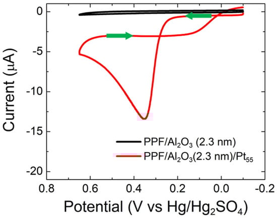
Figure 5.
CVs obtained for CO electrooxidation on PPF/Al2O3(2.3 nm) and PPF/Al2O3(2.3 nm)/Pt55 electrodes. The solutions contained aqueous, CO-saturated 0.10 M HClO4. The electrode potential was scanned between –0.10 and 0.65 V at 0.050 V/s. The experiments were carried out in triplicate for each electrode configuration using independently prepared electrodes to ensure reproducibility.
3.8. Electrochemical Characterization of TiOx Thin Film Rectifying Behavior
Figure 6a shows CVs for bare PPF (black) and PPF/TiO1.9(2.3 nm) working electrodes in Ar-saturated 1.0 mM [Ru(NH3)6]Cl3 (E° = −0.54 V vs. Hg/Hg2SO4) [29] and 0.10 M phosphate buffer in the pH conditions specified in the legend. The purpose of this experiment was to test whether the TiOx thin films exhibited the distinct rectifying and flat-band potential behavior that has previously been reported for defect-rich SnO2 and TiO2 ALD thin films [30,31].
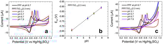
Figure 6.
CVs obtained using (a) PPF/TiO1.9(2.3 nm) and (c) PPF/TiO2.0(2.3 nm) electrodes. The solutions contained aqueous 1.0 mM [Ru(NH3)6]Cl3 and 0.10 M phosphate buffer at the pHs indicated in the legends. The electrode potential was scanned between 0.25 and −1.35 V at 0.050 V/s. The experiments were carried out in triplicate for each electrode configuration using independently prepared electrodes to ensure reproducibility. (b) Plot showing the relationship between Ecp and pH for the indicated working electrode configuration. The error bars in (b) represent the standard deviations from the mean for three measurements that were carried out using independently prepared electrodes.
The CV obtained using the bare PPF electrode (black) reveals reversible electroactivity with well-defined reduction and oxidation peaks at −0.63 and −0.54 V, respectively. The CVs obtained using the PPF/TiO1.9(2.3 nm) working electrode reveal the following features as a function of pH. For the negative-going scan at pH 3.1 (red), there is a sharp cathodic peak at −0.66 V, background activity between −0.80 and −1.2 V (due to the presence of phosphates, Figure S10 in the Supplementary Materials), and a slight cathodic current at −1.3 V arising from the HER [27]. Upon scan reversal, an anodic peak is present at −0.55 V. At pH 5.7 (blue), the sharp cathodic peak moves negative to −0.78 V, and the greatly attenuated anodic peak is present at −0.57 V. At higher pHs, the sharp cathodic peak continues to shift negative (Figure 6b). The anodic peak becomes indistinguishable from the background current at the higher pHs.
The results shown in Figure 6a,b lead to the following three conclusions. First, PPF/TiO1.9 working electrodes exhibit strong rectifying behavior towards Ru(NH3)63+ reduction, which manifests as a significantly sharper cathodic peak compared with that obtained using bare PPF. Second, there is strong correlation between pH and the position of the cathodic peak that follows the relationship expressed in Equation (1) [31].
Here, EFB is the flat-band potential (the potential at which a semiconductor acts as a conductor) and EBE is the band-edge position of a semiconductor [29,31]. This equation indicates that for every unit pH change, there is a 59 mV shift in the flat-band potential. As shown by the plot in Figure 6b, we observe a linear relationship between ECP, the cathodic peak position, and pH with a 53 ± 6 mV slope. Third, as the pH increases, the anodic faradaic current decreases and completely disappears at pH 7.9. This decrease at the high pHs is a consequence of Equation (1). Specifically, at high pH, the flat-band potential of TiO1.9 is far from the standard potential of Ru(NH3)63+ (E° = −0.54 V). For example, at pH 7.9 (pink), the TiO1.9 flat-band potential lies outside of the potential range where reduced Ru(NH3)63+ can be re-oxidized. As a result, no anodic current is observed.
Figure 6c shows CVs for the same experiment discussed in the previous paragraph, but for a fully oxidized TiO2.0 thin film. With fairly minor differences in peak positions and the magnitude of the HER current, this set of CVs is very similar to those in Figure 6a. Note that the higher HER current for TiO2.0 is consistent with TiO2.0 thin film electrochemical activity that we have observed previously [10].
Notably, The TiO2.0 CVs do not follow Equation (1) as clearly as the CVs for TiO1.9. This is the most apparent at pHs 6.7 and 7.9, where the cathodic peaks appear at the same position (−0.88 V). In addition, as pH increases the anodic faradaic current at PPF/TiO2.0 diminishes faster than that of PPF/TiO1.9. This can be explained by the decrease in oxygen vacancies, or defect points, in the lattice structure of the TiO2.0 film [32].
The key point of the foregoing discussion is that the TiOx (x = 1.9; and 2.0) thin films reveal intrinsic n-type semiconducting characteristics that control the electrochemical response of the PPF/TiOx electrodes. This type of behavior has previously been reported by Grätzel and co-workers for defect-rich TiO2 ALD films [31]. They determined the flat-band potential of a 3 nm thick TiO2 ALD film to be ~0.10 V vs. RHE. This means that TiO2 ALD films will only conduct electrons at potentials more negative than 0.10 V vs. RHE. This finding is consistent with our observation of negligible CO electrooxidation activity at PPF/TiOx/Au147 and PPF/TiOx/Pt55 thin films. As discussed in the next section, however, the mystery remains as to why this semiconducting property should affect tunneling from Au147 or Pt55 NPs to PPF electrodes during CO electrooxidation. This result is particularly confounding because the ORR proceeds efficiently at identically prepared electrodes [10].
4. Summary and Conclusions
We [7,8,9,10] and others [2,3,4,5,6] have reported the experimental verification of the original theory [1] of enhanced tunneling between metal NPs and underlying electrodes separated by an intervening, nonconductive medium. We undertook the present study using TiOx thin films for the electrooxidation of CO as a companion to related studies of the ORR [10]. In the latter case, we observed behavior consistent with the theory, but in the present case, no electroactivity was observed. This finding is perplexing because tunneling across TiOx should be independent of the direction of the current.
To better understand the foregoing result, we designed a number of control experiments. For example, we considered that there might be something special about CO oxidation at AuNPs; therefore, we studied the same electrochemical reaction at PtNPs. In the presence of the TiOx interlayer, no CO electrooxidation activity was observed for either metal. When the TiOx interlayer is absent, however, CO electrooxidation proceeds in accordance with prior literature reports [17,18,19,21,22,23,24,25]. We also replaced the semiconducting TiOx interlayer with insulating Al2O3 and found that CO electrooxidation proceeds as expected. This finding validates the NP-mediated eT mechanism (Scheme 1) for large bandgap dielectrics. This is an important result that has not previously been reported for a complex electrooxidation reaction for Scheme 1b configurations.
Finally, we also studied the electrochemistry of a model redox couple, Ru(NH3)63+/2+, using TiOx interlayers and metal NPs. The results exhibited a pH dependency, which is perplexing because tunneling should not be affected by the nature of the medium intervening between conductors.
We plan to continue investigating the effect of semiconducting thin films on CO electrooxidation activity at metal NPs. Specifically, we are presently studying CO electrooxidation using intervening NiO thin films, which have p-type semiconducting properties. We hope that the results of these experiments will shed light on the present mystery. The results of those experiments will be reported in due course.
Supplementary Materials
The following are available online at: https://www.mdpi.com/article/10.3390/nano12050855/s1, Deposition of ALD thin films on PPF electrodes, Figure S1: TEM micrograph and particle-size distribution histogram for G6NH2(Au147), Figure S2: TEM micrograph and particle-size distribution histogram for G6OH(Pt55), Figure S3: XPS spectra of G6NH2(Au147) and G6OH(Pt55) DENs before and after UV/O3 dendrimer removal procedure, Figure S4: CVs of CO electrooxidation on PPF/G6NH2(Au147) and PPF/G6OH(Pt55) before and after UV/O3 dendrimer removal procedure, Figure S5: CV overlay of Fc(MeOH)2 redox probe at PPF, PPF/TiO1.9 and PPF/TiO2.0 working electrodes, Figure S6: CVs of ORR on PPF/TiO1.9(2.3 nm)/Au147 in acidic and alkaline media, Figure S7: CVs of CO electrooxidation on PPF/TiOx/Au147 with varying TiOx thin film thicknesses, Figure S8: CV overlay of Fc(MeOH)2 redox probe at PPF, and PPF/Al2O3 working electrodes, Figure S9: CVs of CO electrooxidation on PPF/Al2O3/Pt55 with varying Al2O3 thin film thicknesses, Figure S10: CV overlay of pH 3.1 phosphate buffer at PPF/TiO1,9, and PPF/TiO2.0 working electrodes. Refs. [7,10,27,33] cited in Supplementary Materials.
Author Contributions
A.G. was responsible for designing, performing, and analyzing all experiments; R.M.C. was responsible for project administration and funding acquisition. A.G. prepared the original manuscript. R.M.C. edited and revised the manuscript. All authors have read and agreed to the published version of the manuscript.
Funding
We gratefully acknowledge support from the Chemical Sciences, Geosciences, and Biosciences Division, Office of Basic Energy Sciences, Office of Science, U.S. Department of Energy (Contract: DE-SC0010576). We thank the Robert A. Welch Foundation (RMC: Grant F-0032 and GH: Grant F-1841) for sustained support of our research.
Institutional Review Board Statement
Not applicable.
Informed Consent Statement
Not applicable.
Data Availability Statement
The data is available on reasonable request from the corresponding author.
Acknowledgments
We thank the Texas Materials Institute for assistance with TiOx thin film characterization.
Conflicts of Interest
The authors declare no conflict of interest.
References
- Chazalviel, J.-N.; Allongue, P. On the origin of the efficient nanoparticle mediated electron transfer across a self-assembled monolayer. J. Am. Chem. Soc. 2011, 133, 762–764. [Google Scholar] [CrossRef] [PubMed]
- Zhao, J.; Bradbury, C.R.; Fermín, D.J. Long-range electronic communication between metal nanoparticles and electrode surfaces separated by polyelectrolyte multilayer films. J. Phys. Chem. C 2008, 112, 6832–6841. [Google Scholar] [CrossRef]
- Shein, J.B.; Lai, L.M.H.; Eggers, P.K.; Paddon-Row, M.N.; Gooding, J.J. Formation of efficient electron transfer pathways by adsorbing gold nanoparticles to self-assembled monolayer modified electrodes. Langmuir 2009, 25, 11121–11128. [Google Scholar] [CrossRef] [PubMed]
- Kissling, G.P.; Miles, D.O.; Fermín, D.J. Electrochemical charge transfer mediated by metal nanoparticles and quantum dots. Phys. Chem. Chem. Phys. 2011, 13, 21175–21185. [Google Scholar] [CrossRef] [PubMed]
- Ye, H.; Scott, R.W.J.; Crooks, R.M. Synthesis, characterization, and surface immobilization of platinum and palladium nanoparticles encapsulated within amine-terminated poly(amidoamine) dendrimers. Langmuir 2004, 20, 2915–2920. [Google Scholar] [CrossRef] [PubMed]
- Barfidokht, A.; Ciampi, S.; Luais, E.; Darwish, N.; Gooding, J.J. Distance-dependent electron transfer at passivated electrodes decorated by gold nanoparticles. Anal. Chem. 2013, 85, 1073–1080. [Google Scholar] [CrossRef]
- Ostojic, N.; Thorpe, J.H.; Crooks, R.M. Electron transfer facilitated by dendrimer-encapsulated Pt nanoparticles across ultrathin, insulating oxide films. J. Am. Chem. Soc. 2016, 138, 6829–6837. [Google Scholar] [CrossRef]
- Anderson, M.J.; Ostojic, N.; Crooks, R.M. Microelectrochemical flow cell for studying electrocatalytic reactions on oxide-coated electrodes. Anal. Chem. 2017, 89, 11027–11035. [Google Scholar] [CrossRef]
- Ostojic, N.; Duan, Z.; Galyamova, A.; Henkelman, G.; Crooks, R.M. Electrocatalytic study of the oxygen reduction reaction at gold nanoparticles in the absence and presence of interactions with SnOx supports. J. Am. Chem. Soc. 2018, 140, 13775–13785. [Google Scholar] [CrossRef]
- Galyamova, A.; Shin, K.; Henkelman, G.; Crooks, R.M. Effect of TiOx substrate interactions on the electrocatalytic oxygen reduction reaction at Au nanoparticles. J. Phys. Chem. C 2020, 124, 10045–10056. [Google Scholar] [CrossRef]
- Ranganathan, S.; McCreery, R.L. Electroanalytical performance of carbon films with near-atomic flatness. Anal. Chem. 2001, 73, 893–900. [Google Scholar] [CrossRef]
- Gröhn, F.; Bauer, B.J.; Akpalu, Y.A.; Jackson, C.L.; Amis, E.J. Dendrimer templates for the formation of gold nanoclusters. Macromolecules 2000, 33, 6042–6050. [Google Scholar] [CrossRef]
- Strasser, J.W.; Hersbach, T.J.P.; Liu, J.; Lapp, A.S.; Frenkel, A.I.; Crooks, R.M. Electrochemical cleaning stability and oxygen reduction reaction activity of 1-2 nm dendrimer-encapsulated Au nanoparticles. ChemElectroChem 2021, 8, 2545–2555. [Google Scholar] [CrossRef]
- Loussaert, J.A.; Fosdick, S.E.; Crooks, R.M. Electrochemical properties of metal-oxide-coated carbon electrodes prepared by atomic layer deposition. Langmuir 2014, 30, 13707–13715. [Google Scholar] [CrossRef] [PubMed]
- NIST X-ray Photoelectron Spectroscopy Database. Available online: https://srdata.nist.gov/xps/Default.aspx (accessed on 25 October 2020).
- Niemelä, J.-P.; Marin, G.; Karppinen, M. Titanium dioxide thin films by atomic layer deposition: A review. Semicond. Sci. Technol. 2017, 32, 93005. [Google Scholar] [CrossRef]
- Hayden, B.E.; Pletcher, D.; Rendall, M.E.; Suchsland, J.-P. CO oxidation on gold in acidic environments: Particle size and substrate effects. J. Phys. Chem. C 2007, 111, 17044–17051. [Google Scholar] [CrossRef]
- Rodriguez, P.; Plana, D.; Fermin, D.J.; Koper, M.T. New insights into the catalytic activity of gold nanoparticles for CO oxidation in electrochemical media. J. Catal. 2014, 311, 182–189. [Google Scholar] [CrossRef] [Green Version]
- Geng, D.; Lu, G. Size effect of gold nanoparticles on the electrocatalytic oxidation of carbon monoxide in alkaline solution. J. Nanopart. Res. 2007, 9, 1145–1151. [Google Scholar] [CrossRef]
- Boddy, P.J. Oxygen evolution on semiconducting TiO2. J. Electrochem. Soc. 1968, 115, 199. [Google Scholar] [CrossRef]
- Abe, K.; Uchida, H.; Inukai, J. Electro-oxidation of CO saturated in 0.1 M HClO4 on basal and stepped Pt single-crystal electrodes at room temperature accompanied by surface reconstruction. Surfaces 2019, 2, 23. [Google Scholar] [CrossRef] [Green Version]
- Anderson, R.M.; Zhang, L.; Wu, D.; Brankovic, S.R.; Henkelman, G.; Crooks, R.M. A Theoretical and experimental in-situ electrochemical infrared spectroscopy study of adsorbed CO on Pt dendrimer-encapsulated nanoparticles. J. Electrochem. Soc. 2016, 163, H3061–H3065. [Google Scholar] [CrossRef] [Green Version]
- Weir, M.G.; Myers, V.S.; Frenkel, A.I.; Crooks, R.M. In situ X-ray absorption analysis of ∼1.8 nm dendrimer-encapsulated Pt nanoparticles during electrochemical CO oxidation. ChemPhysChem 2010, 11, 2942–2950. [Google Scholar] [CrossRef] [PubMed]
- Lai, S.C.S.; Lebedeva, N.P.; Housmans, T.H.M.; Koper, M.T.M. Mechanisms of carbon monoxide and methanol oxidation at single-crystal electrodes. Top. Catal. 2007, 46, 320–333. [Google Scholar] [CrossRef] [Green Version]
- Lebedeva, N.; Koper, M.; Herrero, E.; Feliu, J.; van Santen, R. Cooxidation on stepped Pt[n(111) × (111)] electrodes. J. Electroanal. Chem. 2000, 487, 37–44. [Google Scholar] [CrossRef]
- Pourbaix, M. Atlas of Electrochemical Equilibria in Aqueous Solutions; Perfamon Press: Oxford, UK, 1966. [Google Scholar]
- Torresi, R.M.; Cámara, O.R.; de Pauli, C.P.; Giordano, M.C. Hydrogen evolution reaction on anodic titanium oxide films. Electrochim. Acta 1987, 32, 1291–1301. [Google Scholar] [CrossRef]
- Filatova, E.O.; Konashuk, A.S. Interpretation of the changing the band gap of Al2O3 depending on its crystalline form: Connection with different local symmetries. J. Phys. Chem. C 2015, 119, 20755–20761. [Google Scholar] [CrossRef]
- Bard, A.J.; Faulkner, L.R. Electrochemical Methods: Fundamentals and Applications, 2nd ed.; John Wiley: Chichester, NY, USA, 2001. [Google Scholar]
- Kavan, L.; Steier, L.; Grätzel, M. Ultrathin buffer layers of SnO2 by atomic layer deposition: Perfect blocking function and thermal stability. J. Phys. Chem. C 2017, 121, 342–350. [Google Scholar] [CrossRef]
- Kavan, L.; Tétreault, N.; Moehl, T.; Grätzel, M. Electrochemical characterization of TiO2 blocking layers for dye-sensitized solar cells. J. Phys. Chem. C 2014, 118, 16408–16418. [Google Scholar] [CrossRef]
- Jayashree, S.; Ashokkumar, M. Switchable intrinsic defect chemistry of titania for catalytic applications. Catalysts 2018, 8, 601. [Google Scholar] [CrossRef] [Green Version]
- Powell, C. X-ray Photoelectron Spectroscopy Database XPS, Version 4.1, NIST Standard Reference Database 20. 1989. Available online: https://srdata.nist.gov/xps/ (accessed on 18 December 2021). [CrossRef]
Publisher’s Note: MDPI stays neutral with regard to jurisdictional claims in published maps and institutional affiliations. |
© 2022 by the authors. Licensee MDPI, Basel, Switzerland. This article is an open access article distributed under the terms and conditions of the Creative Commons Attribution (CC BY) license (https://creativecommons.org/licenses/by/4.0/).