Article

Introduce Ce3+ Ions to Realize Enhancement of C+L Band Luminescence of KMnF3: Yb, Er Nanoparticles

State Key Laboratory on Integrated Optoelectronics, College of Electronic Science & Engineering, Jilin University, Changchun 130012, China
*
Author to whom correspondence should be addressed.
Nanomaterials 2023, 13(15), 2153; https://doi.org/10.3390/nano13152153
Submission received: 10 June 2023 / Revised: 19 July 2023 / Accepted: 21 July 2023 / Published: 25 July 2023
(This article belongs to the Special Issue Amorphous and Nanostructured Materials for Optoelectronic Devices)

Abstract

:
Polymer-based waveguide amplifiers are essential components in integrated optical systems, as their gain bandwidths directly determine the operating wavelength of optical circuits. However, development of the wideband gain media has been challenging, making it difficult to fabricate devices with broadband amplification capability. Rare earth ion-doped nanoparticles (NPs) are a key component in the gain media, and their full width at half maximum (FWHM) of the emission peak decides the final gain bandwidth of the gain media. Here, KMnF3: Yb, Er, Ce@KMnF3: Yb NPs with the broad full width at half maximum (FWHM) of the emission peak covering the S+C band was prepared. The NPs were synthesized using a hydrothermal method, and the FWHM of the emission peak of NPs reached 76 nm under the excitation of a 980 nm laser. The introduction of Ce3+ ions and a core-shell structure coating greatly enhanced the emission intensity of NPs at C band. Since KMnF3: Yb, Er, Ce@KMnF3: Yb NPs have exceptional broadband luminescence properties at C band, KMnF3: Yb, Er, Ce@KMnF3: Yb NPs can be the potential gain medium in the future polymer-based waveguide amplifiers.

1. Introduction

Rare earth ion-doped nanoparticles (NPs) have attracted much attention since their excellent optical properties. The fluoride nanoparticles can be used in solar cells, biomarkers, in vivo drug delivery, photocatalysis, biological imaging, cancer therapy, optical waveguide amplifiers, anti-counterfeiting, and other fields [1,2,3,4,5,6,7,8,9,10,11,12]. Rare earth ion-doped nanoparticles (NPs) have attracted much attention due to their excellent optical properties compared with the conventional metal nanoparticles [13,14,15]. Recently, the rare earth ions-doped NPs have gained widespread acceptance as a key component in the gain medium for the fabrication of waveguide amplifiers [16,17]. The gain bandwidth of a waveguide amplifier was determined by the emission bandwidth of the NPs doped in the gain medium. Due to the 4I13/24I15/2 transition of Er3+ ions located at 1.53 μm, the luminescence peaks of Er3+ ions coincide well with the C band [18]. Therefore, Er3+ ions-doped NPs can be utilized in C-band waveguide amplifiers. Specially, the waveguide amplifiers based on KMnF3: Yb, Er NPs have been reported recently because of the broadband luminescence properties in C band of the NPs [19]. However, the low luminescence intensity of KMnF3: Yb, Er NPs makes the NPs difficult for practical requirements. In order to obtain Er3+-doped optical waveguide amplifier with high-gain, it is necessary to obtain a gain medium with intensive luminescence characteristics. The improvement of the luminescence properties of KMnF3: Yb, Er NPs becomes a challenge. So far, several methods have been proposed to enhance the luminescence intensity of Er3+-doped fluoride at 1.53 μm. The first strategy is to increase the transition rate from the highly excited state energy level of Er3+ to the 4I13/2 energy level [20,21], thereby increasing the population of Er3+ at the 4I13/2 energy level. And finally, the luminescence intensity at 1.53 μm can be enhanced due to the increase of radiative transition 4I13/24I15/2 energy level. The second strategy is to coat the surface of nanometer-sized core particles with a shell, which can repair the surface defect of the cores and effectively shield the emissive lanthanide ions near the surface from quenchers in the surroundings. The core-shell structure enhances the luminescence intensity at 1.53 μm of Er3+, thereby improving the luminescence properties of KMnF3: Yb, Er NPs [22,23,24,25,26].
In this paper, we choose KMnF3 as the matrix material since the FWHM of emission peak of the Er3+ ions-doped KMnF3 NPs is broader than that of the typical NaYF4 [27]. We prepared KMnF3: Yb, Er NPs via a hydrothermal method, and the influence of Yb3+ and Er3+ concentrations on the luminescence intensity at 1.53 μm of the NPs was investigated. And the doping concentrations of Yb3+ and Er3+ ions were found when Er3+ ion had the strongest luminescence at 1.5 μm. In order to further enhance the luminescence intensity at 1.53 μm, Ce3+ ions were introduced due to the existence of the energy transfer process between Ce3+ and Er3+: 4I11/2 (Er3+) + 2F5/2 (Ce3+) → 4I13/2 (Er3+) + 2F7/2 (Ce3+) [28]. We also investigated the relationship between the Ce3+ concentration and the luminescence intensity at 1.53 μm of KMnF3: Yb, Er, Ce NPs. And the doping concentration of Ce3+ ion was found when Er3+ ion had the strongest luminescence at 1.5 μm. In order to reduce surface quenching, a core-shell structure was also introduced. Finally, we obtained core-shell NPs (KMnF3: Yb, Er, Ce@KMnF3: Yb) with strong luminescence at 1.53 μm.

2. Experiment Details

YCl3·6H2O (99.99%), YbCl3·6H2O (99.99%), ErCl3·6H2O (99.99%), CeCl3·6H2O(99.99%) were purchased from Yutai Chemical Reagent, Shandong, China. Oleic Acid (OA, 500 mL) was purchased from Alpha Aesop Company, Shanghai, China. Ethanol (98%) and cyclohexane (99%) was obtained from Beijing Fine Chemical Company, Beijing, China. KOH (98%), KF·2H2O (98%), MnCl2·2H2O (98%) were purchased from Aladdin, Shanghai, China. All chemicals were used without further purification.

2.1. Preparation of KMnF3: Yb, Er, Ce NPs

First, 12 mmol KOH was dropped in a 50 mL beaker containing 10 mL oleic acid, 5 mL ethanol and 3 mL deionized water under stirring. About 30 min later, another water solution of 0.4 mmol chloride (the four chlorides of YCl3·6H2O, YbCl3·6H2O, ErCl3·6H2O, CeCl3·6H2O, and MnCl2·2H2O are 0.4 mmol in total) was also added drop by drop. About 30 min later, a 1 mL water solution of 3.5 mmol KF·2H2O was added dropwise. After stirring thoroughly, the solution was transferred to a hydrothermal reactor and heated to 200 °C for 3 h. The reaction solution was naturally cooled to room temperature, and the obtained KMnF3: Yb, Er, Ce nanoparticles were washed three times with ethanol and cyclohexane and dried to obtain powdery KMnF3: Yb, Er, Ce nanoparticles.
Next, 0.2 mmol of the as-prepared KMnF3: Yb, Er, Ce nanoparticles were dissolved in cyclohexane as core to induce the subsequent shell.

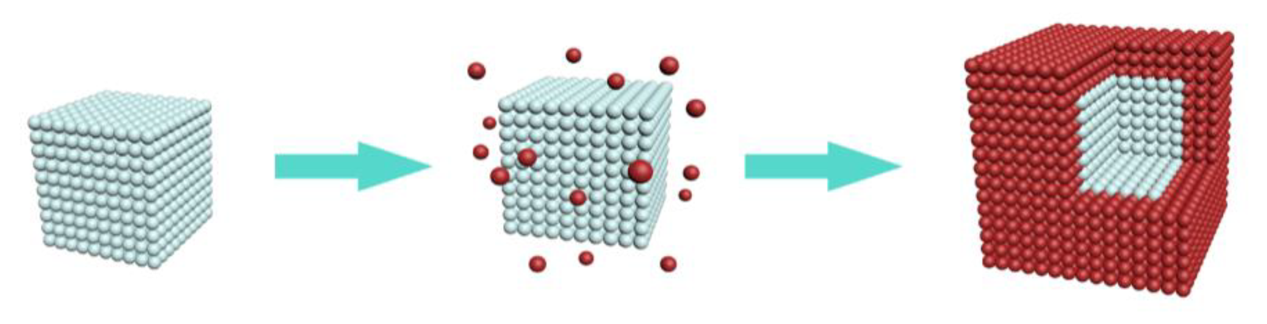
2.2. Preparation of KMnF3: Yb, Er, Ce@KMnF3: Yb Core-Shell NPs

Next, 12 mmol KOH was dropped in a 50 mL beaker containing 10 mL oleic acid, 5 mL ethanol, and 3 mL deionized water under stirring. About 30 min later, another water solution of 0.4 mmol chloride (the four chlorides of YCl3·6H2O, YbCl3·6H2O, ErCl3·6H2O, CeCl3·6H2O, and MnCl2·2H2O are 0.4 mmol in total) was also added drop by drop. About 30 min later, a 1 mL water solution of 3.5 mmol KF·2H2O was added dropwise. At last, a 5 mL solution containing core NPs was dropped into the beaker. After stirring thoroughly, the solution was transferred to a hydrothermal reactor and heated to 200 °C for 12 h. The reaction solution was naturally cooled to room temperature, and the obtained KMnF3: Yb, Er, Ce@KMnF3: Yb nanoparticles were washed three times with ethanol and cyclohexane and then dried to obtain powdery KMnF3: Yb, Er, Ce@KMnF3: Yb nanoparticles.

2.3. Characterization

The phase of the NPs was characterized by X-ray powder diffraction (XRD) (Model Rigaku Ru-200b), using a nickel-filtered Cu-Kα radiation (λ = 1.5406 Å), and the scan ranged from 10° to 70°. The morphology of the particles was characterized by JEM-2100F electron microscope (Tokyo, Japan) at 200 KV. Under the excitation of a 980 nm laser diode, the emission spectrum at 1.53 μm of the sample was collected with a SPEX1000M spectrometer (HORIBA Group, Kyoto, Japan) at room temperature, and the fixed power density was 70 W·cm2 (the slit width was 0.2 mm).

3. Results and Discussion

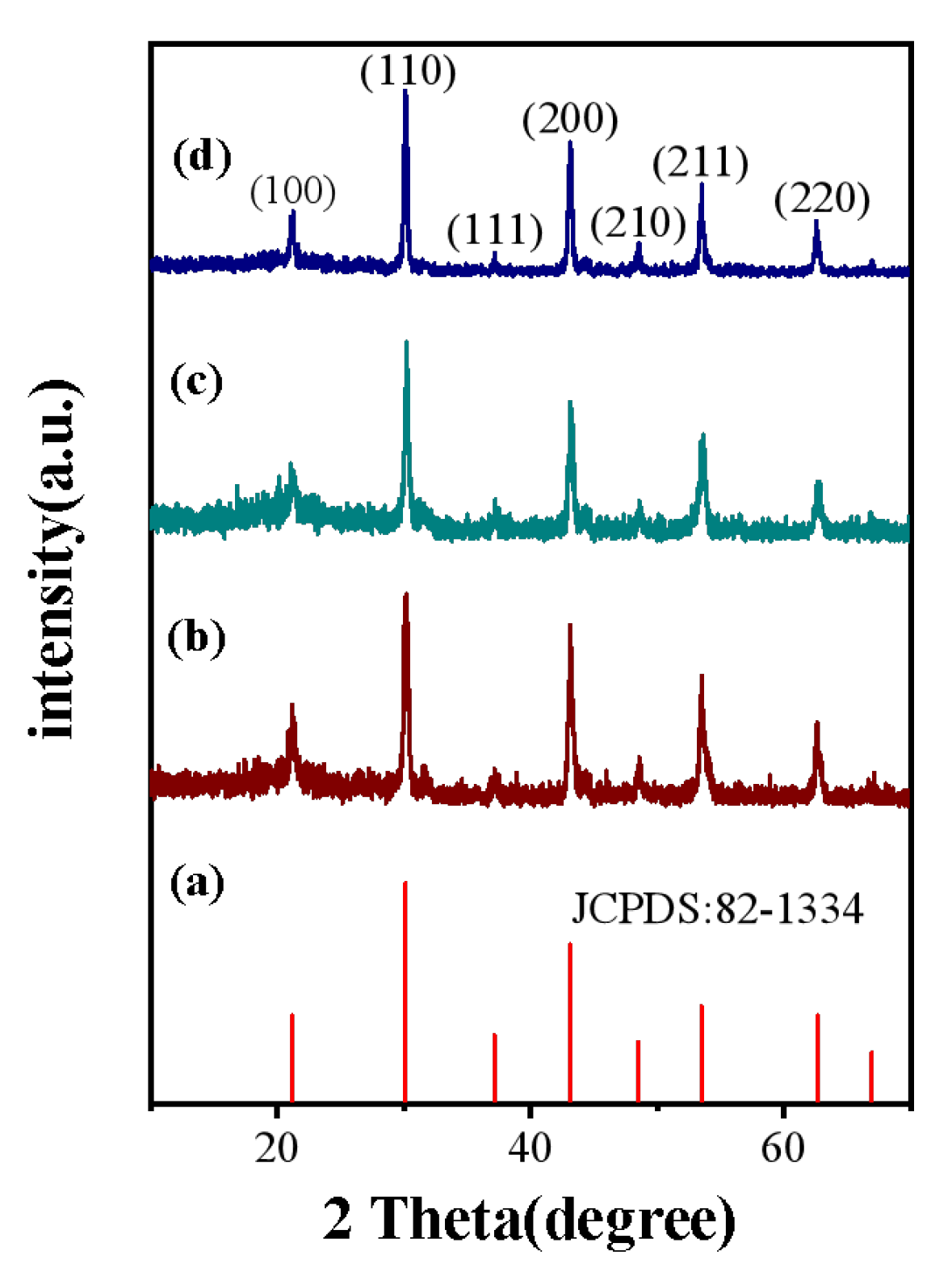
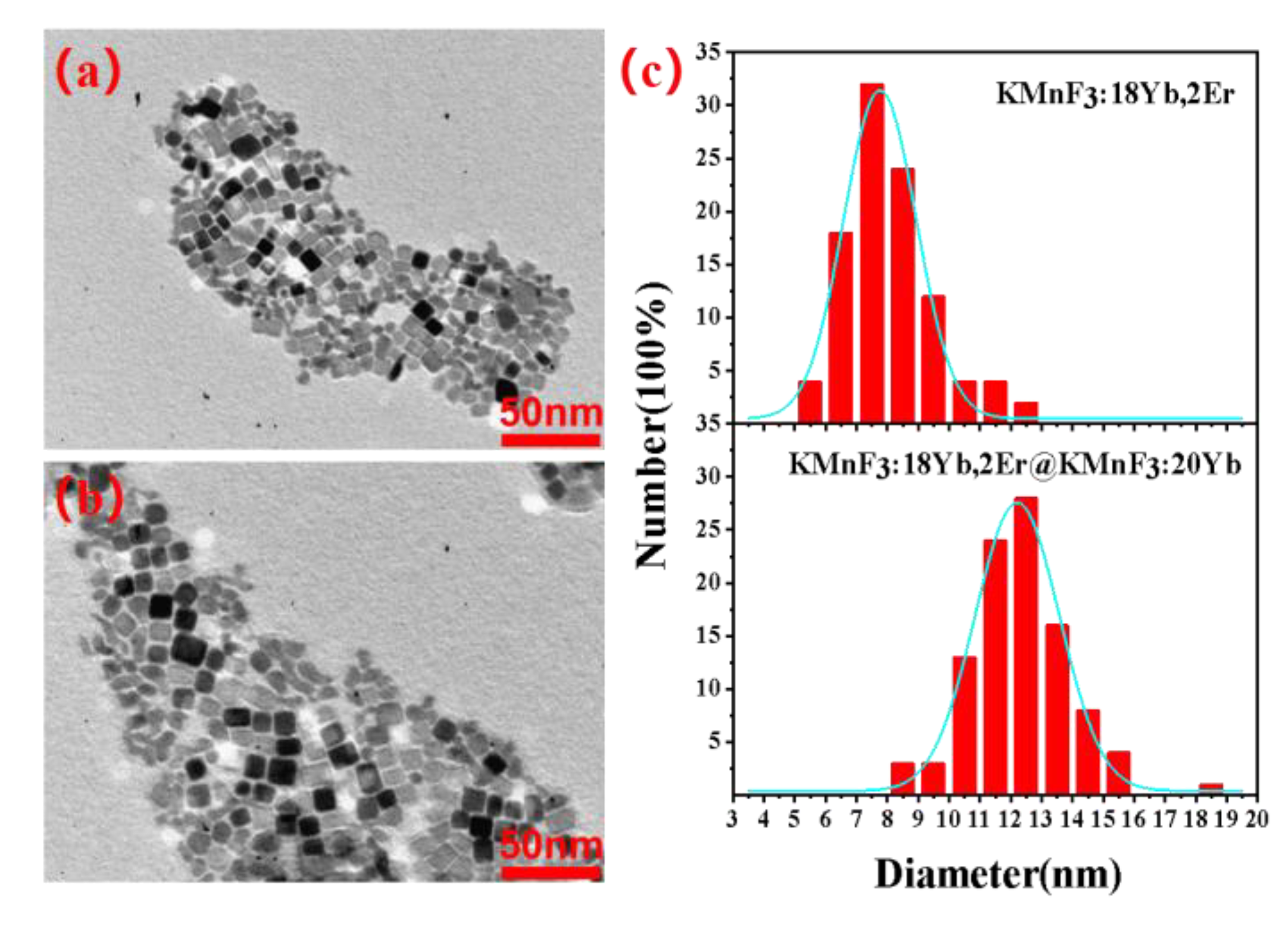
3.1. Crystal Structure and Morphology

The KMnF3: Yb, Er and NaYF4: Yb, Er NPs were prepared, and their normalized up-conversion luminescence spectrum and spectrum at 1.53 μm excited by 980 nm laser were shown in Figure 1. It can be seen the luminescence intensity at the 522 nm (2H11/24I15/2) and 540 nm (4S3/24I15/2) of Er3+ was reduced due to the energy transfer between Mn2+ and Er3+ in the KMnF3: Yb, Er NPs. Therefore, the green up-conversion luminescence of KMnF3: Yb, Er NPs was weakened, and the red up-conversion luminescence was highlighted. Thus, KMnF3: Yb, Er NPs exhibits red up-conversion luminescence at 980 nm excitation. It can be seen in the spectrum of Figure 1b that KMnF3: Yb, Er NPs has two luminescence peaks at 1490 nm and 1530 nm, and its FWHM is about 10 nm wider than that of NaYF4: Yb, Er NPs. We believe that difference of emission spectrum at 1.53 μm was due to the different symmetry of the crystal fields of the two materials.
In order to enhance the luminescence intensity at 1.53 μm of KMnF3: Yb, Er NPs, we introduced Ce3+ ions and prepared an active core-shell structure. The phase structure of the resulting product was analyzed on a Model Rigaku Ru-200b X-ray powder diffractometer (XRD) with nickel-filtered Cu Kα radiation (λ = 1.5406 Å). We successfully synthesized KMnF3: 18Yb, 2Er, KMnF3: 18Yb, 2Er, 4Ce and KMnF3: 18Yb, 2Er, 4Ce@KMnF3: 20Yb NPs by hydrothermal method. The diffraction peak was good agreement with the literature value (JCPDS: 82-1334). The diffraction peaks at 21.2°, 30.1°, 37.2°, 43.1°, 48.48°, 53.5°, 62.5° can be ascribed to the (100), (110), (111), (200), (210), (211), and (220) planes. The diffraction peaks of the samples can be indexed to the cubic phase KMnF3. The X-ray diffraction pattern of the sample is shown in Figure 2. In KMnF3 crystals, Mn2+ ions have an ionic radius of 80 Å. The ionic radii of doped ions are as follows: Er3+ (88.1 Å), Yb3+ (85.8 Å), Ce3+ (103.4 Å). The ionic radius of the Yb3+ ion and the Er3+ ion is similar to that of the Mn2+ ion, so the Yb3+ ion and Er3+ ion can occupy the lattice site of the Mn2+ ion well. The ionic radius of the Ce3+ ion is slightly larger than that of the Mn ion, but the doped Ce3+ ion has little effect on the crystal phase of the KMnF3 crystal due to the low doping concentration of the Ce3+ ion.
The schematic diagram and TEM of KMnF3:18Yb, 2Er, 4Ce@KMnF3: 20Yb core-shell structured nanoparticles were shown in the Figure 3 and Figure 4. The cyan pellets represent the core nanoparticles, and the red pellets represent the shell material.

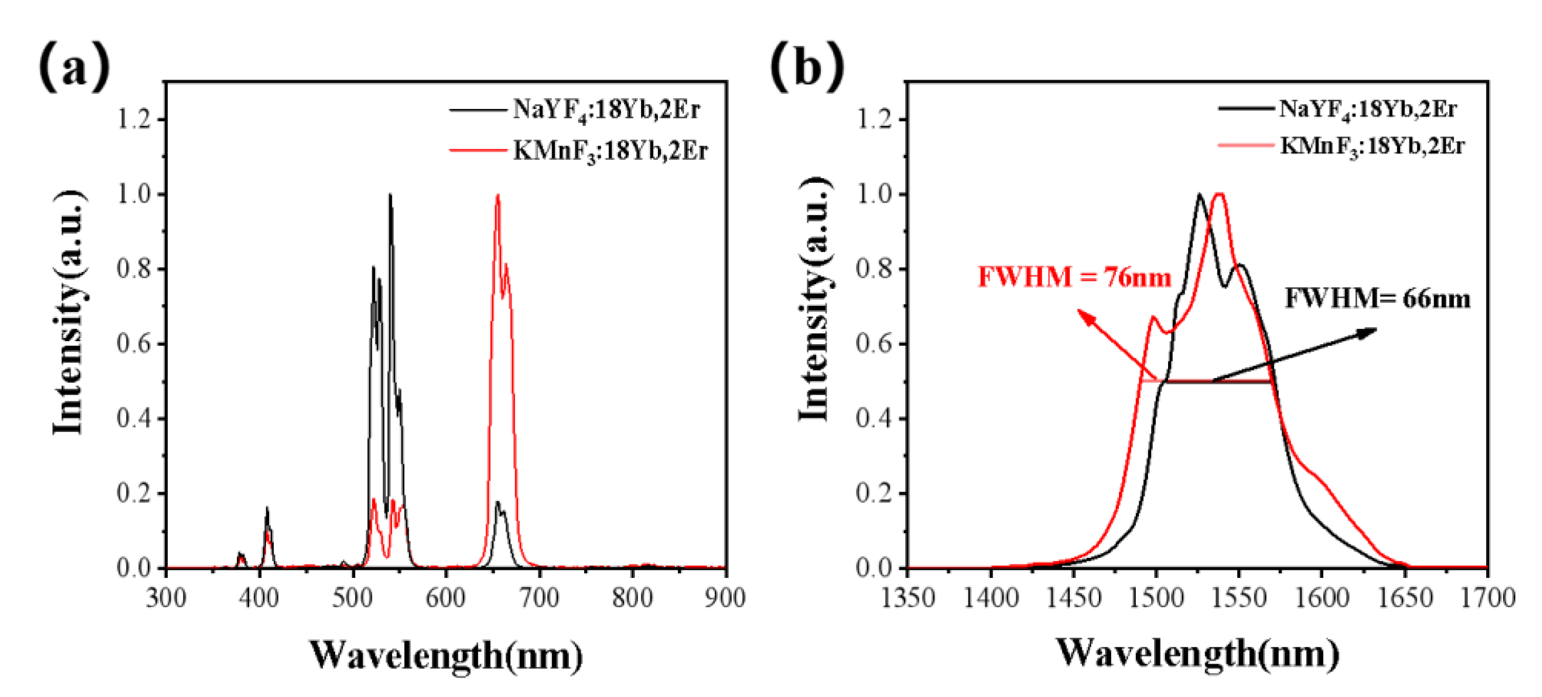
3.2. Optical Properties

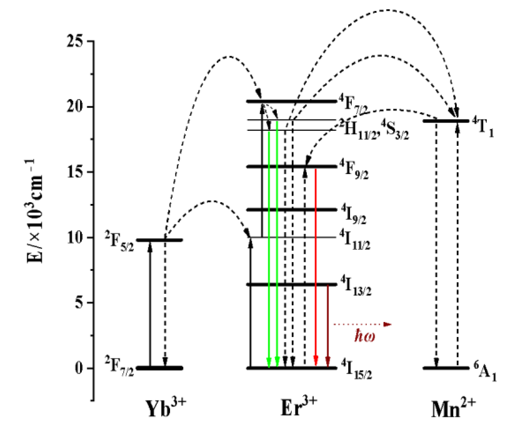
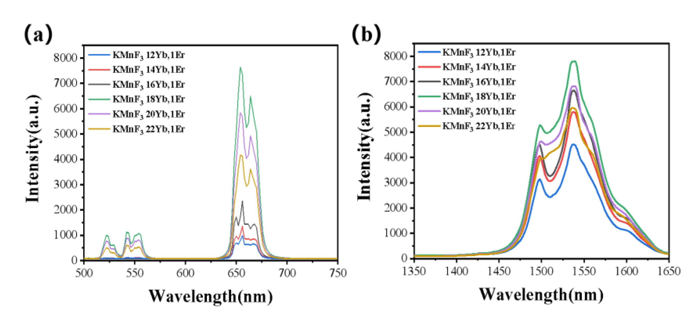
3.2.1. Effect of the Concentration of Yb3+ and Er3+ on the Luminescence Properties of KMnF3: Yb, Er NPs

Most materials exhibit Stokes-shifted, also known as down-conversion emission, where each emitted photon has lower energy than the absorbed photon. However, there are also materials that have the ability to generate anti-Stokes shift luminescence, where the emitted photons have higher energy than the photons used for excitation. Two-photon absorption-based luminescence and second harmonic generation are two examples of anti-Stokes processes that require high-energy pulsed lasers as excitation sources. Depending on the lifetime of the excited state, the two-photon or multi-photon processes require simultaneous or nearly simultaneous absorption of two coherent near-infrared (NIR) photons at high excitation power densities (~106 W cm−2), due to the small two-photon absorption cross-section. From the research on macroscopic inorganic crystals, three major up-conversion mechanisms have been elucidated: (i) ground-state absorption combined with excited-state absorption (GSA/ESA); (ii) energy transfer up-conversion (ETU); and (iii) photon avalanche. Among these categories, ETU is considered to be the most effective up-conversion (UC) mechanism. When a macroscopic crystal is simply doped with a low concentration of a trivalent rare-earth (RE) element, the interactions between ions can be neglected, and GSA/ESA is responsible for the UC process. As the doping concentration increases, the interactions between ions become significant, and the probability of energy transfer between ions in the excited state and the ETU mechanism increases. One approach to improve up-conversion (UC) efficiency is to use sensitizers with a simple energy scheme and high absorption cross-section in the near-infrared (NIR) region. These sensitizers absorb photon energy and transfer it to the up-conversion activators. As we all know, Yb3+ was often used as a sensitizer due its large absorption cross section at 980 nm in the Er3+ and Yb3+ co-doped system, due to the large energy overlap between the 2F5/22F7/2 energy level transition of Yb3+ and the transition of many energy levels of Er3+. Therefore, Yb3+ continuously absorbs 980 nm photons and transfers energy to Er3+ to populate the high-energy level of Er3+ under the excitation of a 980 nm laser diode. And the high-energy level of Er3+ was radiated to the low-energy level through transition, thereby emitting up-conversion luminescence and luminescence at 1.53 μm. In the KMnF3: Yb, Er NPs, the Mn2+ will undergo four energy transfer processes with Er3+: 6A1 (Mn2+) + 2H9/2 (Er3+) → 4T1 (Mn2+) + 4I13/2 (Er3+); 6A1 (Mn2+) + 2H11 (Er3+) → 4T1 (Mn2+) + 4I13/2 (Er3+); 6A1 (Mn2+) + 4S3/2 (Er3+) → 4T1 (Mn2+) + 4I13/2 (Er3+); 4T1 (Mn2+) + 4I15/2 (Er3+) → 6A1 (Mn2+) + 4F9/2 (Er3+) [29]. The energy transfer process in KMnF3: Yb, Er NPs was shown in Figure 5.
The concentration of Yb3+ and Er3+ could greatly affect the luminescence intensity of the up-conversion luminescence and luminescence at 1.53 μm of the KMnF3: Yb, Er NPs. In order to explore the best concentration of Yb3+ and Er3+ in KMnF3: Yb, Er NPs, we performed a series of experiments. First, the concentration of Er3+ was doped at 1 mmol% and the concentration of Yb3+ (12%, 14%, 16%, 18%, 20%, 22%) was changed, then their up-conversion luminescence emission spectrum and luminescence at 1.53 μm emission spectrum was tested under the excitation of a 980 nm laser diode. Figure 6 shows the up-conversion luminescence emission spectrum and luminescence at 1.53 μm emission spectrum with varying Yb3+ concentration under the excitation of a 980 nm laser. We found that the intensity of the luminescence at 1.53 μm gradually increased with increasing Yb3+ concentration from 12% to 18% (as shown in Figure 6b). This was due to the fact that increasing the concentration of Yb3+ doping can enhance the absorption of pump energy. However, it is important to note that at higher concentrations of Yb3+ ions (>18%), the luminescence intensity at 1.53 μm starts to decrease due to concentration quenching caused by the high Yb3+ concentration. Second, the best concentration of Er3+ was determined. The concentration of Yb3+ was doped at 18 mmol% and the Er3+ concentration (0.5%, 1%, 2%, 3%, 4%) was changed, then their up-conversion luminescence emission spectrum and luminescence at 1.53 μm emission spectrum was tested under the excitation of a 980 nm laser diode. Figure 7 shows the up-conversion luminescence emission spectrum and luminescence at 1.53 μm emission spectrum with varying Er3+ concentration under the excitation of a 980 nm laser. We found that the intensity of the luminescence at 1.53 μm gradually increased with increasing Er3+ concentration from 0.5% to 2% (as shown in Figure 7b). This was due to the fact that the Er3+ ion is the luminescence center ion, and the increase of luminescence center increases the luminescence intensity. However, it is important to note that at higher concentrations of Er3+ ions (>2%), the luminescence intensity at 1.53 μm starts to decrease due to concentration quenching caused by the high Er3+ concentration.
Through the above experiments, we determined that the best doping concentration of Yb3+ and Er3+ in the KMnF3 matrix were 18% and 2%.

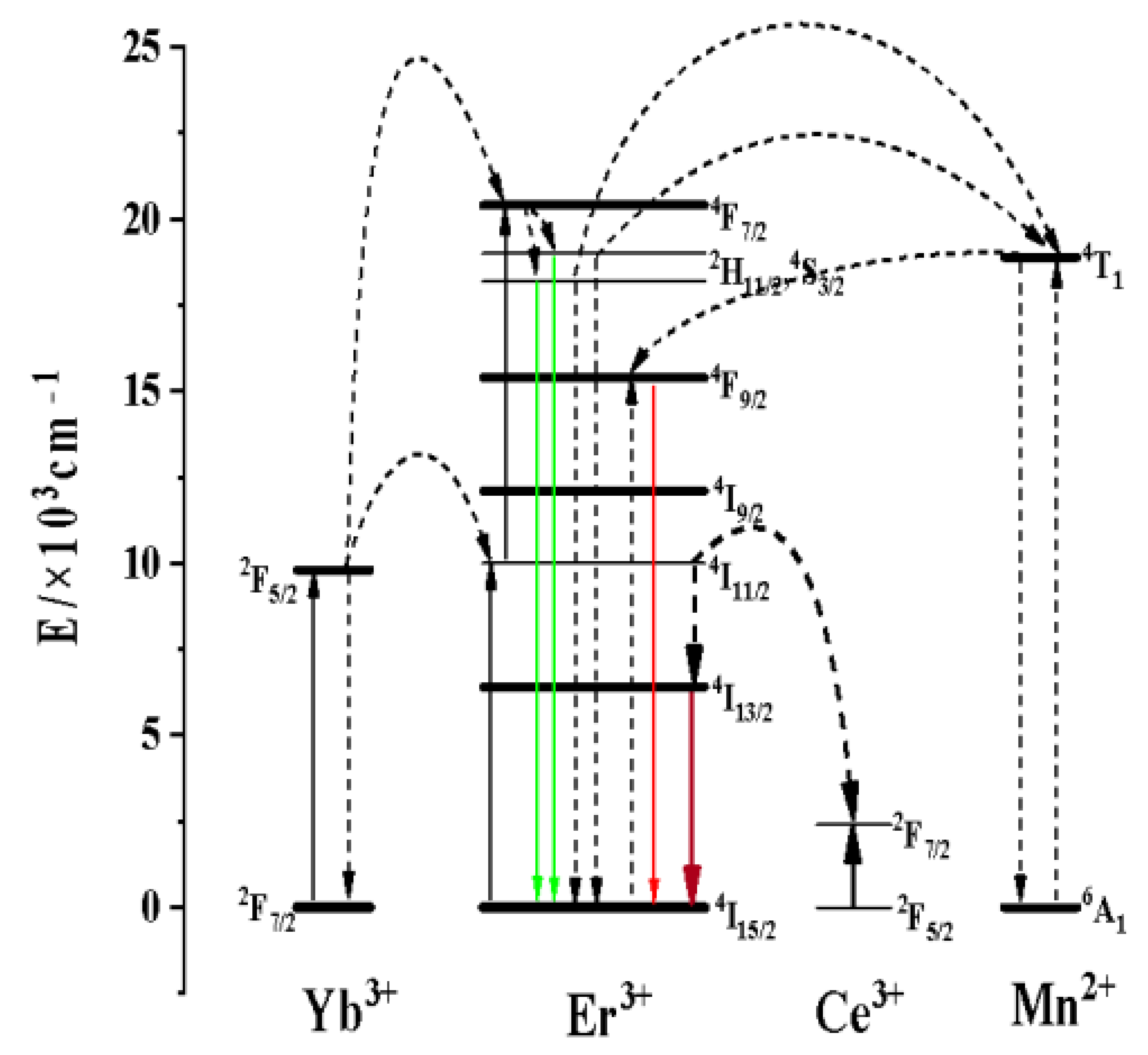
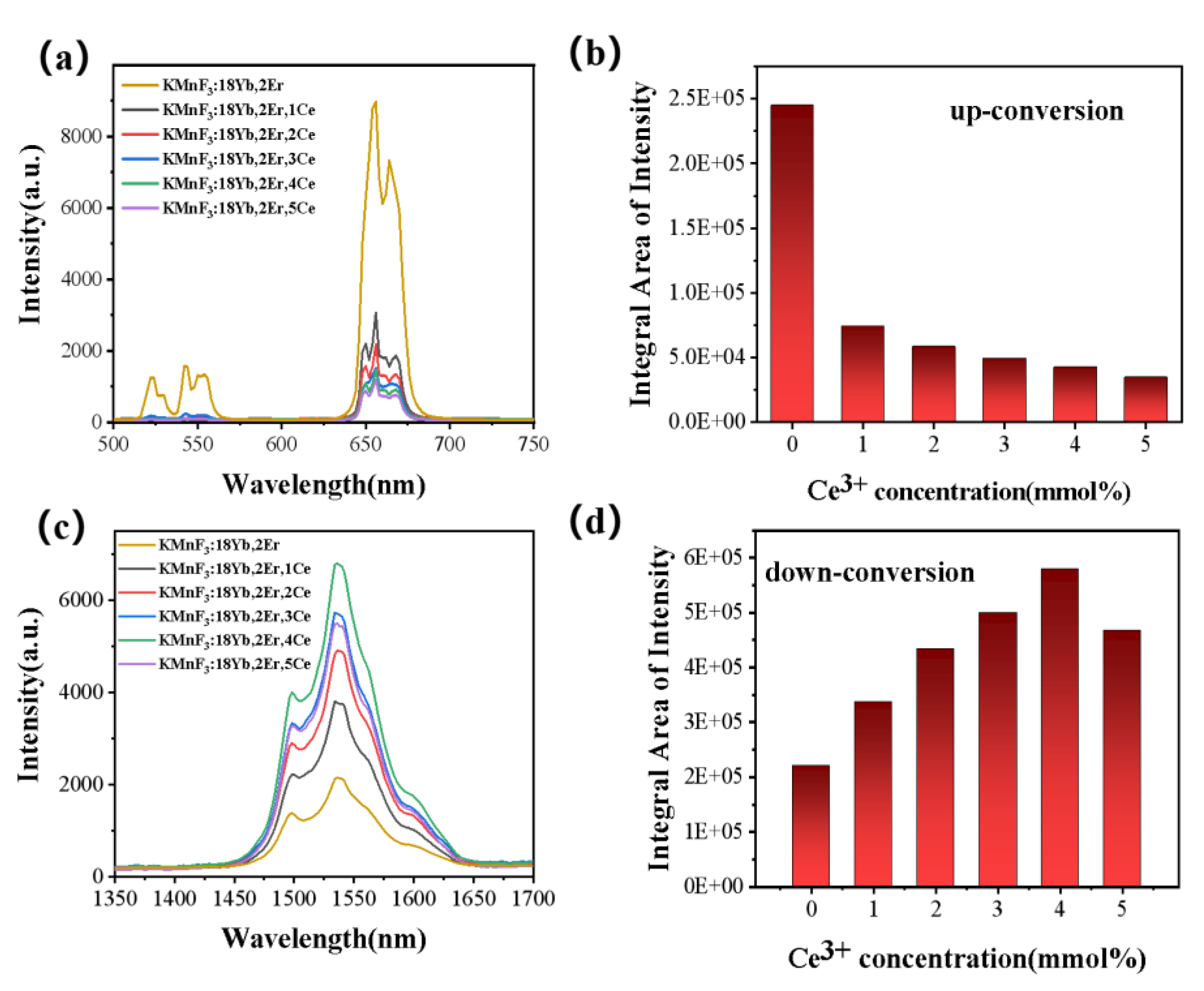
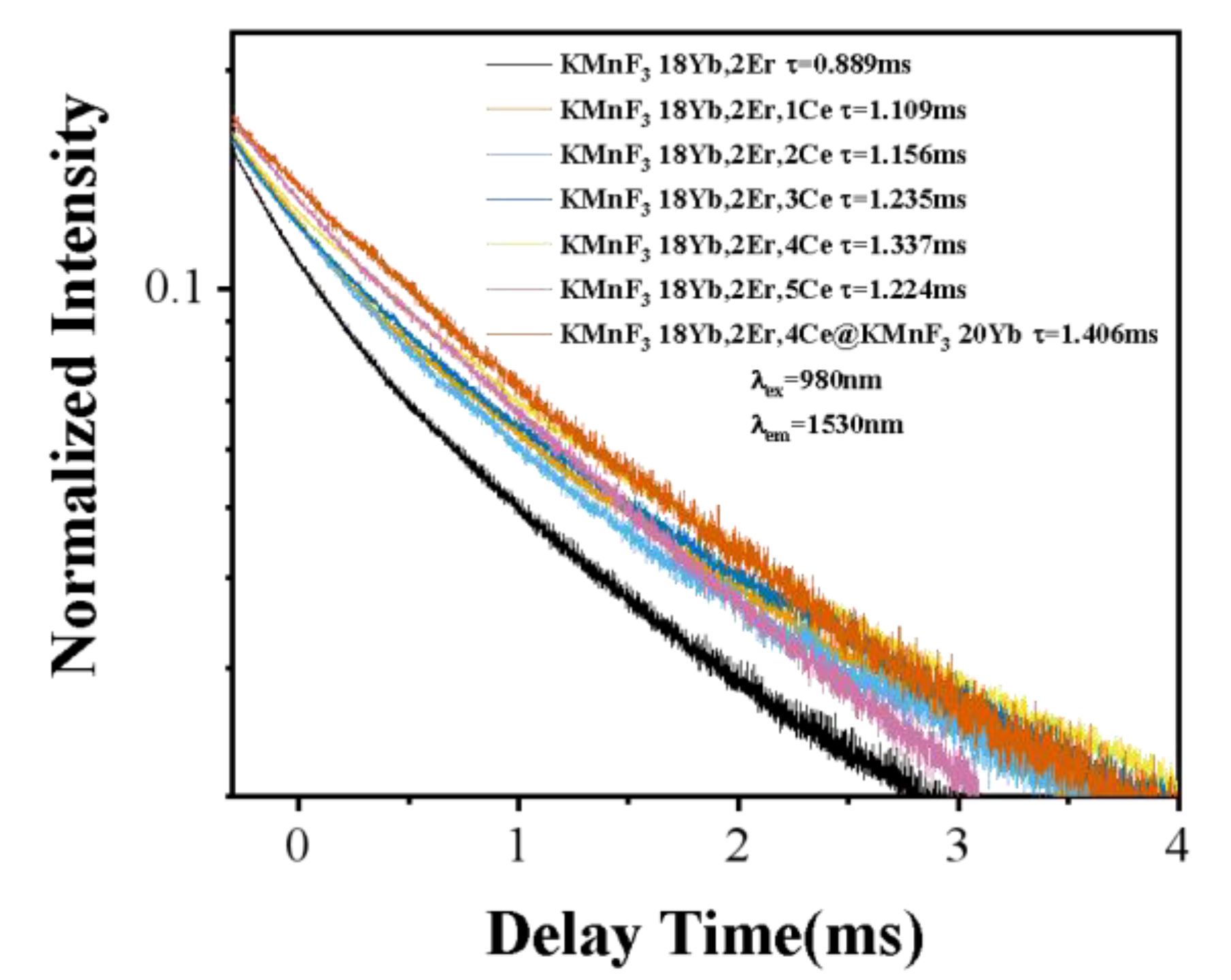
3.2.2. Effect of Ce3+ Concentration on the Luminescence Properties of KMnF3: Yb, Er NPs

After the introduction of Ce3+ ions, the luminescence intensity at 1.53 μm of Er3+ ions was significantly increased. In KMnF3: Yb, Er, Ce NPs, all the energy transfer processes were shown in Figure 8. The Yb3+ ions were excited from the 2F7/2 to the 2F5/2 energy level under the excitation of the 980 nm laser diode, and the energy was transferred to the Er3+ ions to accumulate the higher energy level of the Er3+ ions: 2H9/2, 4F7/2, 2H11/2, 4S3/2, 4F9/2. Among them, 4H11/24I15/2 (≈525 nm), 4S3/24I15/2 (≈545 nm), and 4F9/24I15/2 (655 nm) transitions give up-conversion emission. The 4I13/24I15/2 transition gives luminescence at 1.53 μm. Interestingly, the energy transfer occurs between Ce3+ ions and Er3+ ions with the introduction of Ce3+ ions: 4I11/2 (Er3+) + 2F5/2 (Ce3+) → 4I13/2 (Er3+) + 2F7/2 (Ce3+). As a result, the 4I11/2 energy levels of the Er3+ ions were populated at the 4I13/2 energy level [30,31,32]. The intensity of up-conversion luminescence was reduced, while the luminescence intensity at 1.53 μm was improved after the introduction of Ce3+. As shown in the energy transfer schematic in Figure 8. The energy of the excitation laser at 980 nm is first transferred to the Yb3+ ions, and then the energy is transferred to the 4I11/2 energy level of the Er3+ ions through the energy transfer between the Yb3+ ions and the Er3+ ions. The 4I11/2 energy level of the Er3+ ions can continue to receive energy transferred from the Yb3+ ions, thereby increasing the population of the other excited state energy levels of the Er3+ ions. After the introduction of Ce3+ ions, the energy transfer process occurs between Ce3+ ions and Er3+ ions. The population of the 4I11/2 energy level of Er3+ ions decreases and the population of the 4I13/2 energy level of Er3+ ions increases. The decrease of the population of the 4I11/2 energy level of Er3+ ions leads to the decrease of the population of all other excited state energy levels of Er3+ ions and the weakening of the up-conversion luminescence intensity. The increase of the population of the 4I13/2 energy level of Er3+ ions leads to the increase of the luminescence intensity at 1.5 μm (4I13/24I15/2). As shown in the Figure 9, after the introduction of Ce3+ ion, the intensity of luminescence of the sample at 1.5 μm was significantly increased, while the up-conversion luminescence intensity of the sample was significantly decreased. With the increasing Ce3+ ion concentration, the luminescence intensity of the sample at 1.5 μm has been increased, and the up-conversion luminescence intensity has been decreased. When the Ce3+ ion reaches the optimal doping concentration, the luminescence intensity of the sample reaches the maximum at 1.5 μm. As the Ce3+ ion concentration continued to increase, the luminescence intensity at 1.5 μm of the sample began to weaken.
In order to investigate the best concentration of Ce3+ ions, we measured the up-conversion luminescence spectrum of KMnF3:18Yb, 2Er, xCe (x = 1%, 2%, 3%, 4%, 5%) under the excitation of a 980 nm laser diode, the data was shown in Figure 9a. The luminescence peaks were attributed to the 2H11/24I15/2 (525 nm), 4S3/24I15/2 (545 nm), 4F9/24I15/2 (655 nm).
The luminescence at 1.53 μm of the NPs under the excitation of a 980 nm laser diode gradually increased with the increase of Ce3+ concentration (as shown in Figure 9b). This is due to the energy transfer between Ce3+ and Er3+: 4I11/2 (Er3+) + 2F5/2 (Ce3+) → 4I13/2 (Er3+) + 2F7/2 (Ce3+). This results in an increase in the population of the 4I13/2 level of the Er3+ ion and a decrease in the population of the 4I11/2 level. The increase of the population of the 4I13/2 energy level greatly increases the luminescence intensity of the Er3+ ion at 1.5 μm. When the Ce3+ concentration was 4 mmol%, the luminescence intensity at 1.53 μm of KMnF3: Yb, Er, Ce NPs reaches the maximum under excitation of the 980 nm laser diode (as shown in Figure 9d). As the Ce3+ concentration continues to increase, the luminescence intensity at 1.53 μm begins to weaken, which was due the concentration quenching. Through the above experiments, we determined that the best Ce3+ doping concentration in KMnF3: Yb, Er NPs was 4%. This Ce3+ doping concentration will be used in the subsequent core-shell coating experiments.

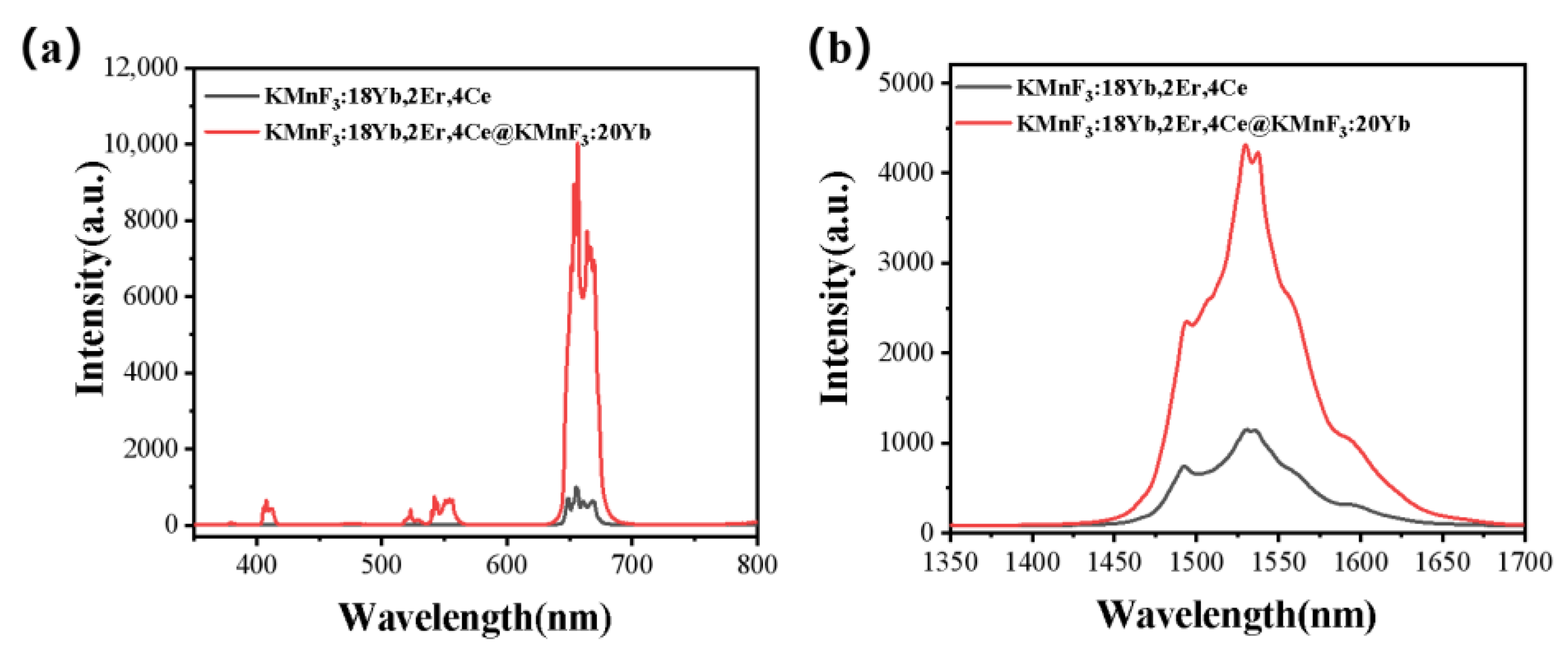
3.2.3. Up-Conversion Luminescence and Luminescence at 1.53 μm Characteristics of Core-Shell KMnF3: Yb, Er, Ce@KMnF3: Yb NPs

We compared the up-conversion luminescence spectrum and luminescence at 1.53 μm of KMnF3:18Yb, 2Er, 4Ce core NPs with KMnF3:18Yb, 2Er, 4Ce@KMnF3:20Yb core-shell NPs under excitation of 980 nm laser diode (as shown in Figure 10). It can be seen that when the active shell layer was coated on the surface of the core NPs, the intensity of up-conversion luminescence and luminescence intensity at 1.53 μm was significantly enhanced. Due to this, the insertion of the shell can inhibit the non-radiative transition [23,24,33], and the Yb3+ ions in the shell can transfer energy from the pump source to the core. Thereby, the active shell contributes to the enhancement of the luminescence intensity of the up-conversion and luminescence intensity at 1.53 μm [34].
In addition, the lifetime of the 4I13/2 energy level of Er3+ in KMnF3: 18Yb, 2Er, KMnF3:18Yb, 2Er, xCe (x = 1%, 2%, 3%, 4%, 5%) and KMnF3:18Yb, 2Er, 4%Ce@KMnF3: 20Yb NPs was measured under excitation of 980 nm pulsed laser with a pulse width of 400 µs and a frequency of 50 HZ as the excitation source. The result was shown in Figure 11. Each of the delay curves can be fitted well with a single-exponential function as I = I 0 exp t / τ , where I 0 is the initial emission intensity at t = 0 and τ is the lifetime of the monitored level. We found that after the introduction of Ce3+ ions, the lifetime of the 4I13/2 energy level was increased. This was because after the introduction of Ce3+ ions, the energy transfer occurs between Ce3+ ions and Er3+ ions with the introduction of Ce3+ ions: 4I11/2 (Er3+) + 2F5/2 (Ce3+) → 4I13/2 (Er3+) + 2F7/2 (Ce3+). After energy transfer occurs, the population of 4I13/2 level of Er ion increases, which leads to the increase of the lifetime of 4I13/2 level. The lifetime of the 4I13/2 level increases with the increase of Ce ion concentration. When the doping concentration of Ce ion reaches 4%, the luminescence of the Er ion at 1.5 μm and the lifetime of the 4I13/2 energy level reach the maximum. With the continuous increase of Ce ion doping concentration, the luminescence of the Er ion at 1.5 μm and the lifetime of 4I13/2 level will decrease, which is caused by concentration quenching. In a series of lifetime curves, the core-shell structure sample has the longest lifetime. This is due to growing an active shell on the core NPs, and the increase in lifetime is due to the surface passivation effect, which leads to a reduction in nonradiative relaxation rate.

4. Conclusions

In summary, we prepared KMnF3 NPs by a hydrothermal method. Through multiple sets of control experiments, we found the best concentration of Yb3+ and Er3+ when the KMnF3: Yb, Er has the strongest luminescence at 1.53 μm under excitation of 980 nm laser diode. The introduction of Ce3+ ions enhanced the luminescence intensity at 1.53 μm of KMnF3: Yb, Er NPs, and the optimal concentration of Ce3+ was found. The preparation of the core-shell structure further enhanced luminescence intensity at 1.53 μm of KMnF3: Yb, Er NPs. It can be seen from the spectrum that after the active shell was coated, the intensity of up-conversion luminescence and luminescence intensity at 1.53 μm of the NPs under the excitation of 980 nm laser diode was greatly enhanced; this also shows that the core-shell structure can well inhibit the surface quenching effect. Since KMnF3: Yb, Er, Ce@KMnF3: Yb NPs have good broadband luminescence properties at 1530 nm, they can be the potential gain medium in the future polymer-based waveguide amplifiers.

Author Contributions

Conceptualization, H.C.; Formal analysis, H.C. and Z.J.; Investigation, Y.Y., Y.F. and J.Y.; Data curation, D.L. and Y.D.; Writing—original draft, H.C.; Writing—review & editing, W.Q. and D.Z. All authors have read and agreed to the published version of the manuscript.

Funding

The authors acknowledge support from the National Natural Science Foundation of China (U22A2085, 2174150 and 62075082), National Key Research and Development Program of China (2021YFB2800500).

Data Availability Statement

The data supporting the findings of this study are available from the authors upon reasonable and appropriate request.

Conflicts of Interest

The authors declare no conflict of interest.

References

  1. Li, X.; Zhang, F.; Zhao, D. Lab on upconversion nanoparticles: Optical properties and applications engineering via designed nanostructure. Chem. Soc. Rev. 2015, 44, 1346–1378. [Google Scholar] [CrossRef] [PubMed]
  2. Shan, G.B.; Demopoulos, G.P. Near-infrared sunlight harvesting in dye-sensitized solar cells via the insertion of an upconverter-TiO2 nanocomposite layer. Adv. Mater. 2010, 22, 4373–4377. [Google Scholar] [CrossRef] [PubMed]
  3. Wu, Y.-M.; Cen, Y.; Huang, L.-J.; Yu, R.-Q.; Chu, X. Upconversion fluorescence resonance energy transfer biosensor for sensitive detection of human immunodeficiency virus antibodies in human serum. Chem. Commun. 2014, 50, 4759–4762. [Google Scholar] [CrossRef] [PubMed]
  4. Bagheri, A.; Arandiyan, H.; Boyer, C.; Lim, M. Lanthanide-doped upconversion nanoparticles: Emerging intelligent light-activated drug delivery systems. Adv. Sci. 2016, 3, 1500437. [Google Scholar] [CrossRef] [Green Version]
  5. de Wild, J.; Rath, J.; Meijerink, A.; Van Sark, W.; Schropp, R. Enhanced near-infrared response of a-Si: H solar cells with β-NaYF4: Yb3+ (18%), Er3+ (2%) upconversion phosphors. Sol. Energy Mater. Sol. Cells 2010, 94, 2395–2398. [Google Scholar] [CrossRef] [Green Version]
  6. Qin, W.; Zhang, D.; Zhao, D.; Wang, L.; Zheng, K. Near-infrared photocatalysis based on YF3: Yb3+, Tm3+/TiO2 core/shell nanoparticles. Chem. Commun. 2010, 46, 2304–2306. [Google Scholar] [CrossRef]
  7. Shen, J.-W.; Yang, C.-X.; Dong, L.-X.; Sun, H.-R.; Gao, K.; Yan, X.-P. Incorporation of computed tomography and magnetic resonance imaging function into NaYF4: Yb/Tm upconversion nanoparticles for in vivo trimodal bioimaging. Anal. Chem. 2013, 85, 12166–12172. [Google Scholar] [CrossRef]
  8. Wang, C.; Xu, C.; Xu, L.; Sun, C.; Yang, D.; Xu, J.; He, F.; Gai, S.; Yang, P. A novel core–shell structured upconversion nanorod as a multimodal bioimaging and photothermal ablation agent for cancer theranostics. J. Mater. Chem. B 2018, 6, 2597–2607. [Google Scholar] [CrossRef]
  9. Peng, J.; Sun, Y.; Zhao, L.; Wu, Y.; Feng, W.; Gao, Y.; Li, F. Polyphosphoric acid capping radioactive/upconverting NaLuF4: Yb, Tm, 153Sm nanoparticles for blood pool imaging in vivo. Biomaterials 2013, 34, 9535–9544. [Google Scholar] [CrossRef]
  10. Wang, F.; Han, Y.; Lim, C.S.; Lu, Y.; Wang, J.; Xu, J.; Chen, H.; Zhang, C.; Hong, M.; Liu, X. Simultaneous phase and size control of upconversion nanocrystals through lanthanide doping. Nature 2010, 463, 1061–1065. [Google Scholar] [CrossRef]
  11. Wang, C.; Cheng, L.; Liu, Z. Drug delivery with upconversion nanoparticles for multi-functional targeted cancer cell imaging and therapy. Biomaterials 2011, 32, 1110–1120. [Google Scholar] [CrossRef]
  12. Adusumalli, V.N.; Sarkar, S.; Mahalingam, V. Strong Single-Band Blue Emission from Colloidal Ce3+/Tm3+-Doped NaYF4 Nanocrystals for Light-Emitting Applications. Chemphyschem 2015, 16, 2312–2316. [Google Scholar] [CrossRef] [PubMed]
  13. Mody, V.; Siwale, R.; Singh, A.; Mody, H. Introduction to metallic nanoparticles. J. Pharm. Bioallied Sci. 2010, 2, 282–289. [Google Scholar] [CrossRef] [PubMed]
  14. Malik, M.; Iqbal, M.A.; Iqbal, Y.; Malik, M.; Bakhsh, S.; Irfan, S.; Ahmad, R.; Pham, P.V. Biosynthesis of silver nanoparticles for biomedical applications: A mini review. Inorg. Chem. Commun. 2022, 2022, 109980. [Google Scholar] [CrossRef]
  15. Malik, M.; Iqbal, M.A.; Malik, M.; Raza, M.A.; Shahid, W.; Choi, J.R.; Pham, P.V. Biosynthesis and Characterizations of Silver Nanoparticles from Annona squamosa Leaf and Fruit Extracts for Size-Dependent Biomedical Applications. Nanomaterials 2022, 12, 616. [Google Scholar] [CrossRef]
  16. Zhang, M.; Zhang, W.; Wang, F.; Zhao, D.; Qu, C.; Wang, X.; Yi, Y.; Cassan, E.; Zhang, D. High-gain polymer optical waveguide amplifiers based on core-shell NaYF4/NaLuF4: Yb(3+), Er(3+) NPs-PMMA covalent-linking nanocomposites. Sci. Rep. 2016, 6, 36729. [Google Scholar] [CrossRef] [Green Version]
  17. Lei, K.-L.; Chow, C.-F.; Tsang, K.-C.; Lei, E.N.Y.; Roy, V.A.L.; Lam, M.H.W.; Lee, C.S.; Pun, E.Y.B.; Li, J. Long aliphatic chain coated rare-earth nanocrystal as polymer-based optical waveguide amplifiers. J. Mater. Chem. 2010, 20, 7526–7529. [Google Scholar] [CrossRef]
  18. Chen, C.; Zhang, D.; Li, T.; Zhang, D.; Song, L.; Zhen, Z. Erbium-ytterbium codoped waveguide amplifier fabricated with solutionprocessable complex. Appl. Phys. Lett. 2009, 94, 041119. [Google Scholar] [CrossRef]
  19. Zhang, Y.; Lv, P.; Wang, D.; Qin, Z.; Wang, F.; Zhang, D.; Zhao, D.; Qin, G.; Qin, W. KMnF3: Yb3+,Er3+Core-Active-Shell Nanoparticles with Broadband Down-Shifting Luminescence at 1.5 mum for Polymer-Based Waveguide Amplifiers. Nanomaterials 2019, 9, 463. [Google Scholar] [CrossRef] [Green Version]
  20. Liu, X.; Qiu, J.; Xu, X.; Zhou, D. Effect of Ce3+ Concentration on the Luminescence Properties of Ce3+/Er3+Nb3+ Tri-Doped NaYF4 Nanocrystals. J. Nanosci. Nanotechnol. 2016, 16, 3749–3753. [Google Scholar] [CrossRef]
  21. Huang, B.; Zhou, Y.; Yang, F.; Wu, L.; Qi, Y.; Li, J. The 1.53μm spectroscopic properties of Er3+/Ce3+/Yb3+ tri-doped tellurite glasses containing silver nanoparticles. Opt. Mater. 2016, 51, 9–17. [Google Scholar] [CrossRef]
  22. Ren, W.; Tian, G.; Jian, S.; Gu, Z.; Zhou, L.; Yan, L.; Jin, S.; Yin, W.; Zhao, Y. TWEEN coated NaYF4:Yb,Er/NaYF4 core/shell upconversion nanoparticles for bioimaging and drug delivery. RSC Adv. 2012, 2, 7037–7041. [Google Scholar] [CrossRef]
  23. Boyer, J.C.; Gagnon, J.; Cuccia, L.A.; Capobianco, J.A. Synthesis, Characterization, and Spectroscopy of NaGdF4:  Ce3+, Tb3+/NaYF4 Core/Shell Nanoparticles. Chem. Mater. 2007, 19, 3358–3360. [Google Scholar] [CrossRef]
  24. Jin, S.; Zhou, L.; Gu, Z.; Tian, G.; Yan, L.; Ren, W.; Yin, W.; Liu, X.; Zhang, X.; Hu, Z.; et al. A new near infrared photosensitizing nanoplatform containing blue-emitting up-conversion nanoparticles and hypocrellin A for photodynamic therapy of cancer cells. Nanoscale 2013, 5, 11910–11918. [Google Scholar] [CrossRef] [PubMed] [Green Version]
  25. Zhou, B.; Tao, L.; Tsang, Y.H.; Jin, W. Core–shell nanoarchitecture: A strategy to significantly enhance white-light upconversion of lanthanide-doped nanoparticles. J. Mater. Chem. C 2013, 1, 4313–4318. [Google Scholar] [CrossRef]
  26. Yang, D.; Li, C.; Li, G.; Shang, M.; Kang, X.; Lin, J. Colloidal synthesis and remarkable enhancement of the upconversion luminescence of BaGdF5:Yb3+/Er3+ nanoparticles by active-shell modification. J. Mater. Chem. 2011, 21, 5923–5927. [Google Scholar] [CrossRef]
  27. Fu, Y.; Yang, Y.; Sun, T.; Tang, Y.; Li, J.; Cui, H.; Qin, W.; Wang, F.; Qin, G.; Zhao, D. Polymer-based S-band waveguide amplifier using NaYF4:Yb,Tm-PMMA nanocomposite as gain medium. Opt. Lett. 2022, 47, 154–157. [Google Scholar] [CrossRef]
  28. Zhai, X. Enhancement of 1.53 μm emission band in NaYF4:Er3+,Yb3+,Ce3+ nanocrystals for polymer-based optical waveguide amplifiers. Opt. Mater. Express 2013, 3, 270–277. [Google Scholar] [CrossRef]
  29. Ding, M.Y.; Hou, J.J.; Yuan, Y.J.; Bai, W.F.; Lu, C.H.; Xi, J.H.; Ji, Z.G.; Chen, D.Q. Nd3+/Yb3+ cascade-sensitized single-band red upconversion emission in active-core/active-shell nanocrystals. Nanotechnology 2018, 29, 345704. [Google Scholar] [CrossRef]
  30. Sani, E.; Toncelli, A.; Tonelli, M. Effect of Cerium codoping on Er:BaY2F8 crystals. Opt. Express 2005, 13, 8980–8992. [Google Scholar] [CrossRef]
  31. Shen, S.; Richards, B.; Jha, A. Enhancement in pump inversion efficiency at 980 nm in Er3+, Er3+/Eu3+ and Er3+/Ce3+ doped tellurite glass fibers. Opt. Express 2006, 14, 5050–5054. [Google Scholar] [CrossRef] [PubMed]
  32. Meng, Z.; Yoshimura, T.; Fukue, K.; Higashihata, M.; Nakata, Y.; Okada, T. Large improvement in quantum fluorescence yield of Er3+-doped fluorozirconate and fluoroindate glasses by Ce3+ codoping. J. Appl. Phys. 2000, 88, 2187–2190. [Google Scholar] [CrossRef]
  33. Johnson, N.J.; He, S.; Diao, S.; Chan, E.M.; Dai, H.; Almutairi, A. Direct Evidence for Coupled Surface and Concentration Quenching Dynamics in Lanthanide-Doped Nanocrystals. J. Am. Chem. Soc. 2017, 139, 3275–3282. [Google Scholar] [CrossRef] [PubMed]
  34. Zhang, Y.; Liu, X.; Lang, Y.; Yuan, Z.; Zhao, D.; Qin, G.; Qin, W. Synthesis of ultra-small BaLuF5:Yb3+,Er3+@BaLuF5:Yb3+ active-core–active-shell nanoparticles with enhanced up-conversion and down-conversion luminescence by a layer-by-layer strategy. J. Mater. Chem. C 2015, 3, 2045–2053. [Google Scholar] [CrossRef]
Figure 1. The normalized comparison of the (a) up-conversion spectrum and (b) emission spectrum at 1.53 μm of KMnF3: 18Yb, 2Er and NaYF4: 18Yb, 2Er under the excitation of a 980 nm laser diode.
Nanomaterials 13 02153 g001
Figure 2. XRD patterns of (a) KMnF3 standard card; (b), KMnF3: 18Yb, 2Er; (c), KMnF3: 18Yb, 2Er, 4Ce; (d), KMnF3: 18Yb, 2Er, 4Ce@KMnF3: 20Yb.
Nanomaterials 13 02153 g002
Figure 3. Schematic diagram of KMnF3: 18Yb, 2Er, 4Ce core NPs and KMnF3: 18Yb, 2Er, 4Ce@KMnF3: 20Yb core-shell NPs.
Nanomaterials 13 02153 g003
Figure 4. (a) TEM of the KMnF3: 18Yb, 2Er, 4Ce core NPs; (b) TEM of the KMnF3: 18Yb, 2Er, 4Ce@KMnF3: 20Yb core-shell structured NPs; (c) KMnF3:18Yb, 2Er, 4Ce and KMnF3: 18Yb, 2Er, 4Ce@KMnF3: 20Yb particle size distribution.
Nanomaterials 13 02153 g004
Figure 5. Schematic diagram of energy transfer in KMnF3: Yb, Er nanoparticles under the excitation of a 980 nm laser diode.
Nanomaterials 13 02153 g005
Figure 6. The (a) up-conversion emission spectrum and (b) emission spectrum at 1.53 μm of KMnF3: xYb, 1Er (x = 12%, 14%, 16%, 18%, 20%, 22%) NPs excited by a 980 nm laser diode.
Nanomaterials 13 02153 g006
Figure 7. The (a) up-conversion emission spectrum and (b) emission spectrum at 1.53 μm of KMnF3: 18Yb, xEr (x = 0. 5%, 1%, 2%, 3%, 4%) NPs excited by a 980 nm laser diode.
Nanomaterials 13 02153 g007
Figure 8. Schematic diagram of energy transfer process in KMnF3: Yb, Er, Ce NPs.
Nanomaterials 13 02153 g008
Figure 9. KMnF3: 18Yb, 2Er, xCe (x = 1%, 2%, 3%, 4%, 5%) under the excitation of 980 nm laser diode (a) up-conversion luminescence spectrum and (b) luminescence spectrum at 1.53 μm and (c) up-conversion luminescence spectrum and (d) luminescence spectrum at 1.53 μm integral area under different Ce3+ concentrations.
Nanomaterials 13 02153 g009
Figure 10. (a) Up-conversion luminescence spectrum and (b) luminescence spectrum at 1.53 μm of KMnF3: 18%Yb, 2%Er, 4%Ce and KMnF3: 18%Yb, 2%Er, 4%Ce@KMnF3: 20%Yb excited by a 980 nm laser diode.
Nanomaterials 13 02153 g010
Figure 11. Photoluminescence decay curves of the 4I13/2 level of Er3+.
Nanomaterials 13 02153 g011
Disclaimer/Publisher’s Note: The statements, opinions and data contained in all publications are solely those of the individual author(s) and contributor(s) and not of MDPI and/or the editor(s). MDPI and/or the editor(s) disclaim responsibility for any injury to people or property resulting from any ideas, methods, instructions or products referred to in the content.

