Article

Enhanced Lithium Storage Performance of α-MoO3/CNTs Composite Cathode

1
Key Laboratory for Photonic and Electronic Bandgap Materials, Ministry of Education, School of Physics and Electronic Engineering, Harbin Normal University, Harbin 150025, China
2
Shaanxi Key Laboratory of Green Preparation and Functionalization for Inorganic Materials, School of Materials Science and Engineering, Shaanxi University of Science and Technology, Xi’an 710021, China
*
Authors to whom correspondence should be addressed.
Nanomaterials 2023, 13(15), 2272; https://doi.org/10.3390/nano13152272
Submission received: 9 June 2023 / Revised: 2 August 2023 / Accepted: 3 August 2023 / Published: 7 August 2023
(This article belongs to the Special Issue Nanostructures for Wastewater Treatment and Energy Conversion)

Abstract

:
Orthorhombic molybdenum oxide (α-MoO3), as a one-layered pseudocapacitive material, has attracted widespread attention due to its high theoretical lithium storage specific capacity (279 mAh/g) for lithium-ion batteries’ cathode. Nevertheless, low conductivity, slack reaction kinetics, and large volume change during Li+ ions intercalation and deintercalation seriously limit the practical application of α-MoO3. Herein, we added a small number of CNTs (1.76%) to solve these problems in a one-step hydrothermal process for preparing the α-MoO3/CNTs composite. Because of the influence of CNTs, the α-MoO3 nanobelt in the α-MoO3/CNTs composite had a larger interlayer spacing, which provided more active sites and faster reaction kinetics for lithium storage. In addition, CNTs formed a three-dimensional conductive network between α-MoO3 nanobelts, enhanced the electrical conductivity of the composite, accelerated the electron conduction, shortened the ion transport path, and alleviated the structural fragmentation caused by the volume expansion during the α-MoO3 intercalation and deintercalation of Li+ ions. Therefore, the α-MoO3/CNTs composite cathode had a significantly higher rate performance and cycle life. After 150 cycles, the pure α-MoO3 cathode had almost no energy storage, but α-MoO3/CNTs composite cathode still retained 93 mAh/g specific capacity.

1. Introduction

Nowadays, to cope with the ever-increasing energy demands, it is imperative to develop energy storage technologies with low cost, high capacity, and long cycle life [1]. In typical energy storage technologies, rechargeable lithium-ion batteries (LIBs) stand out for their environmental friendliness, high energy density, high operating voltage, and no memory effect. However, with the rapid development of portable electronic devices, electric vehicles, grid applications, etc., researchers should continue to dive into the exploration of higher-capacity electrode materials to meet the increasing needs for higher energy-density storage, although LiCoO2, LiMn2O4, LiFePO4, and LiNi0.33Co0.33Mn0.33O2 cathode materials have been commercialized [2]. Transition metal oxides with high reversible capacity and excellent electrochemical performance based on pseudocapacitive energy storage mechanisms are good candidates for cathode materials [3]. As a cathode material of LIBs, MoO3 has piqued broad research interests due to its abundant resources, stable chemical properties, and high theoretical specific capacity [4,5,6,7]. Taking the widely studied thermodynamically stable orthorhombic stable a-phase MoO3 (α-MoO3) with anisotropic [5] as an example, its unique layered structure consists of two edge-sharing layers of [MoO6] octahedra sharing corners along the crystal orientation [001] and [100], and a two-dimensional structure stacked by van der Waals forces along [010]. This two-dimensional structure of α-MoO3 allows ions (such as Li+) to intercalate into the interlayer, leading to highly redox active Mo6+/Mo5+ and Mo5+/Mo4+ double electron reactions, with a high specific capacity of nearly 300 mAh/g [8]. In our previous work on α-MoO3 as an anode for Li+ storage based on conversion reactions, the intercalation reaction of α-MoO3 as a cathode had better structural stability and a faster kinetic reaction [9]. In recent studies, xia et al. monitored the structural changes of MoO3 during lithium storage by in situ TEM, providing intuitive evidence for its lithiation and delithiation behavior [10]. The MoO3 cathode modified by ammoniation by Wang et al. showed good stability in the voltage of 1–3.5 V [8]. The electrodeposition of MoO3 nanoparticles on conductive materials by Zhang et al. showed excellent kinetics [11]. However, the inherent low conductivity and poor rate performance of α-MoO3 as a transition metal oxide still limit its application [12]. In addition, during the initial cycle, an irreversible phase transition occurs near the discharge platform at 2.8 V, which causes α-MoO3 layer deformation and the capacity to rapidly decay in subsequent cycles. To solve these problems, researchers have enhanced pseudocapacitance storage by constructing nanostructures and manufacturing oxygen vacancies, electrical conductivity by pre-intercalation and compounding with carbon materials, the electrochemical performance of α-MoO3, etc. [13,14,15,16]. Although the lithium storage performance of α-MoO3 has been improved, the preparation methods are often complicated, and the improvement of lithium storage performance is still insufficient. For example, the fabrication of oxygen defects requires strict control of the etching time. The pre-intercalation is necessary for controlling the amount of ion insertion and prevention of detachment during subsequent cycles. Several studies have indicated that ensuring the uniformity of composite materials when compounding with carbon materials is difficult [11,13,17,18,19,20,21,22,23]. Therefore, it is still challenging to effectively improve the electrochemical performance of α-MoO3 of lithium storage to meet future large-scale production needs.
Herein, unique α-MoO3/carbon nanotubes (CNTs) composite cathode was synthesized by adding a small amount of functionalized CNTs (1.76%) in a one-step hydrothermal process, and we used hydrophobic multiwall carbon nanotubes (CNTs). To facilitate the synthesis of α-MoO3/CNTs composite with an internal embedded structure, we treated the CNTs to make them rich in functional groups. Specifically, we acidified the multiwall CNTs to make them hydrophilic. Given the influence of CNTs, the α-MoO3 nanobelt in the α-MoO3/CNTs composite introduced oxygen vacancies and had a larger interlayer spacing, providing more active sites and faster kinetic reaction for lithium storage. In addition, the CNTs formed a three-dimensional conductive network between α-MoO3 nanobelts, enhancing the composite’s electrical conductivity, accelerating the electron conduction, shortening the ion transport path, and alleviating the structural fragmentation caused by the volume expansion in the Li+ storage process. Thus, the rate performance and the cycle life of α-MoO3/CNTs composite were significantly improved compared to pure α-MoO3.

2. Results and Discussion

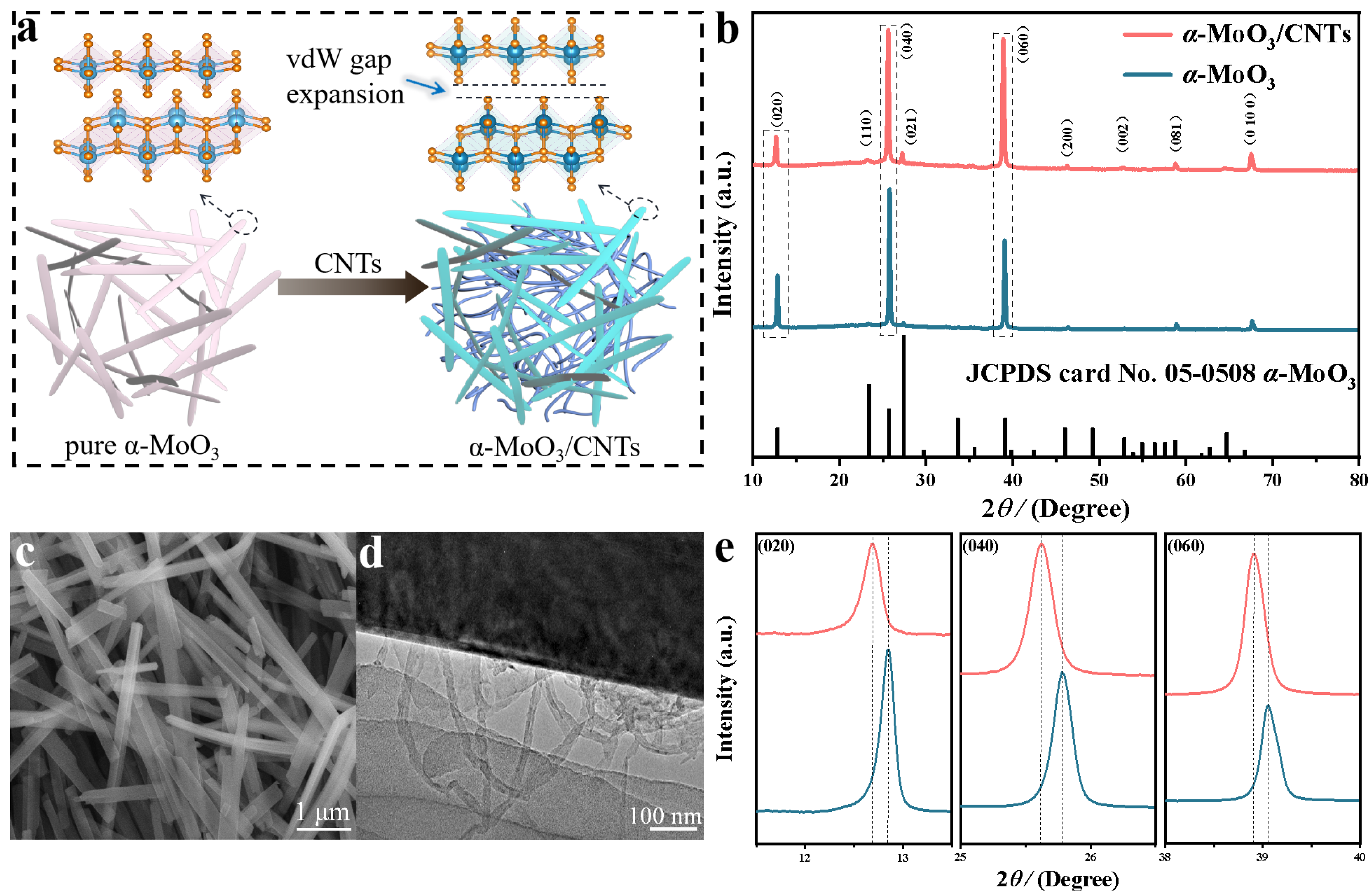
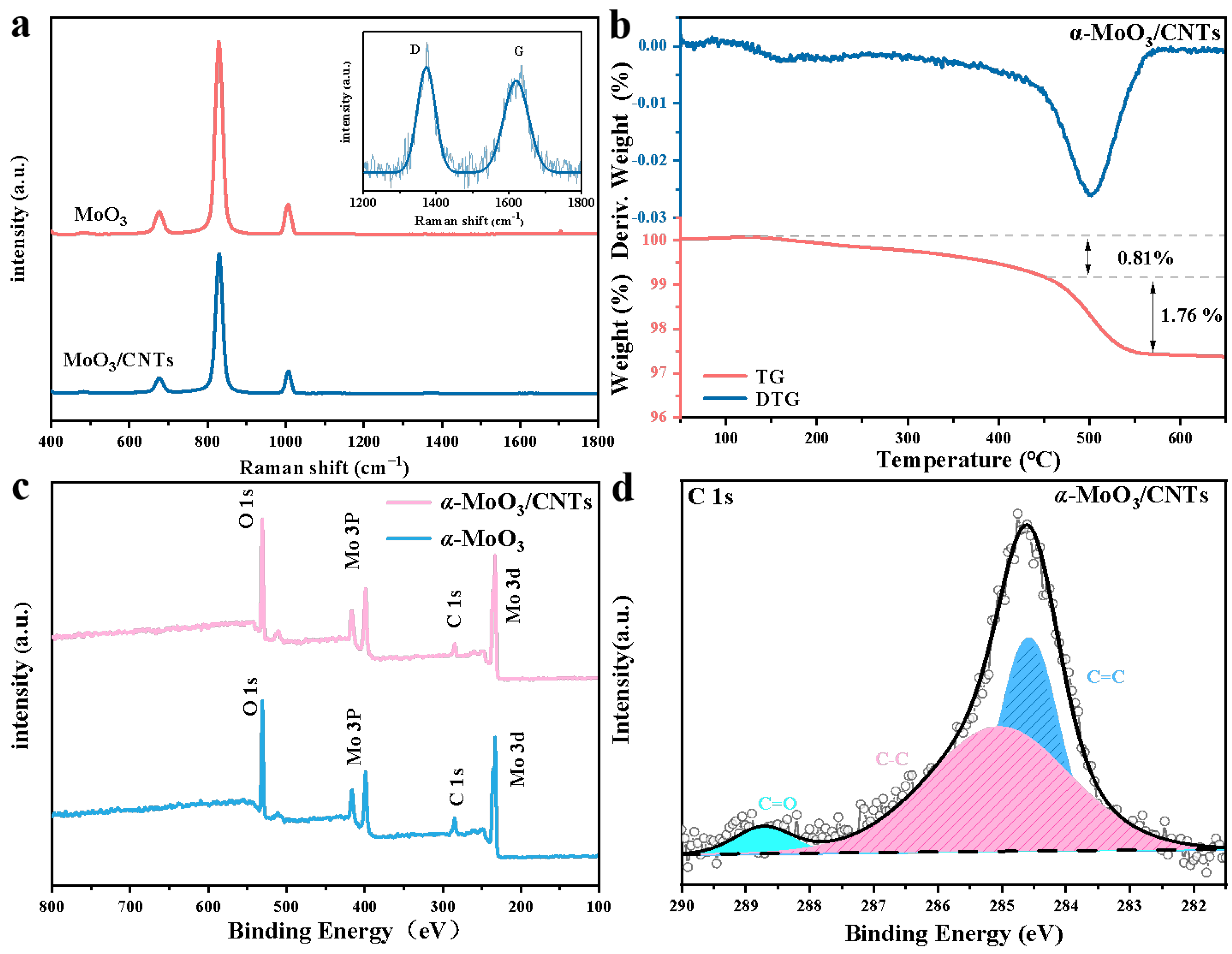
2.1. Structure and Morphology Analysis

The α-MoO3/CNTs composite was prepared by a simple one-step hydrothermal method. Figure 1a shows the effect of CNTs on α-MoO3 in the α-MoO3/CNTs composites, including the expanded interlayer distance α-MoO3 structure and CNTs’ three-dimensional conductive network in the α-MoO3/CNTs composite. This point is confirmed by the X-ray diffraction (XRD) results of α-MoO3/CNTs composite and pure α-MoO3. As shown in Figure 1b, the X-ray excitation source was monochrome Al Ka (hv = 1486.6 eV), power 150 W, X-ray beam spot 500 μm, and an energy analyzer through an energy of 30 eV. Due to the low content of CNTs, the α-MoO3/CNTs composite corresponds well to orthorhombic α-MoO3 (JCPDS No. 05-0508, space group: Pbnm (62)) [24,25,26]. The α-MoO3/CNTs composite had better crystallinity without other impurity phases, and the (0k0) peak was very sharp, which further illustrates that the layered structure of α-MoO3 held together along the b-axis and preferred orientation growth along the [001] direction. This is consistent with the long nanobelt shape in the SEM image. The SEM image (Figure 1c) shows a thin and uniform nanobelt structure of the α-MoO3/CNTs composite with a length of about 1–6 μm [27,28,29,30]. Compared with pure α-MoO3, the composite nanobelts were shorter, and the TEM image in Figure 1d indicates the presence of bent CNTs between the α-MoO3 nanobelts. The CNTs were uniformly distributed between the α-MoO3 nanobelts to form a serviceable conductive network, which greatly increased the conductivity during the energy storage process. It is worth noting that the XRD patterns were partially enlarged, as shown in Figure 1e. Compared with the (0k0) peak position of pure α-MoO3, the peak position of the CNTs added α-MoO3/CNTs composite was significantly shifted to a smaller angle. This verifies that the CNTs embedded α-MoO3 in the α-MoO3/CNTs composite had a larger interlayer spacing than the pure α-MoO3.
Figure 2a is the Raman spectra comparison of the α-MoO3/CNTs composite and pure α-MoO3. Both the D-peak and G-peak are the Raman characteristic peaks of C-atom crystals, which were observed around 1300 cm−1 and 1600 cm−1, respectively. The D and G bands in the Raman spectra can verify the presence of a small number of CNTs in the α-MoO3/CNTs composite. The characteristic bands of α-MoO3 in the composite were observed at 1006 cm−1 (Ag, νas Mo=O stretch) and 828 cm−1 (Ag, νas Mo=O stretch), which corresponds to the axially symmetric stretching vibration of the terminal Mo=O along the a-axis and b-axis, and the characteristic bands of α-MoO3 were observed at 676 cm−1 (B2g, B3g, νas Mo-O-Mo stretch) and 482 cm−1 (Ag, νas Mo-O-Mo stretch and bend), which corresponded to the bridge oxygen bond with weakly bound oxygen along the c-axis. The peak on the right side of Figure 2a is the D-band and G-band of the CNTs in the α-MoO3/CNTs composite, and the D-band and G-band frequencies were 1373 and 1620 cm−1, respectively. The ID/IG = 0.876, indicating that the disorder of CNTs was high, which is consistent with the TEM image of Figure 1d. To determine the content of CNTs in the α-MoO3/CNTs composite, an thermogravimetric analysis of the composites was carried out. Figure 1b shows the TG and DTG curves of the α-MoO3/CNTs composite at a 10 °C/min heating rate in an air atmosphere. The apparent weight loss from 150 °C to 450 °C was the reaction of bound water in the composites, and the apparent weight loss from 450 °C to 550 °C could be ascribed to the decomposition of CNTs. Therefore, the content of CNTs was 1.76%, and a small amount of CNTs greatly influenced the structure of α-MoO3 in the α-MoO3/CNTs composite. The XPS spectra of the α-MoO3/CNTs composite and pure α-MoO3 are shown in Figure 2c,d. The XPS survey spectrum signifies the coexistence of Mo, O, and C elements in the α-MoO3/CNTs composite. The high-resolution spectrum of Mo 3d in the composite (Supplementary Figure S1a) shows a pair of Mo6+ peaks and a pair of weaker Mo5+ peaks. The 232.8 and 235.95 eV peaks belonged to Mo 3d5/2 and Mo 3d3/2 peaks of Mo6+. The 231.7 and 234.85 eV peaks corresponded to Mo 3d5/2 and Mo 3d3/2 peaks of Mo5+. Because of the presence of Mo5+, the α-MoO3 component in the α-MoO3/CNTs composite contains oxygen defected. Compared to pure α-MoO3, the peak position was almost not shifted, but the Mo5+/Mo6+ of α-MoO3/CNTs composite was more extensive because CNTs made the synthesized α-MoO3 contain more defects. The value of Mo5+ and Mo6+ was 0.072, so the calculation of α-MoO3−x with defects was x = 0.03 in the composite. The strong peak at 530.6 eV in the O 1s high-resolution spectrum of Supplementary Figure S1b corresponded to the Mo-O bond in α-MoO3, while 531 eV corresponded to the C=O bond. The content of the C=O bond in the composite was lower due to the presence of CNTs. The C 1s high-resolution spectra Figure 2d of α α-MoO3/CNTs composite can be fitted into three peaks of 284.6, 285.1, and 288.75 eV, corresponding to C=C, C-C, and C=O bonds, respectively. The high content of the C-C bond was from the CNTs.
Due to the addition of CNTs in the hydrothermal reaction, some oxygen defects were introduced during the synthesis of α-MoO3. The α-MoO3 had a larger interlayer spacing but still maintained the nanobelt structure in the α-MoO3/CNTs composite. If the content of CNTs is increased, the [MoO6] octahedra structure will be more distorted and the nanobelts will be broken during the synthesis process. The α-MoO3/CNTs composite synthesized by adding a small number of CNTs in a one-step hydrothermal process is quite different from the microstructure of pure α-MoO3 and will have a greater effective effect on the energy storage process.

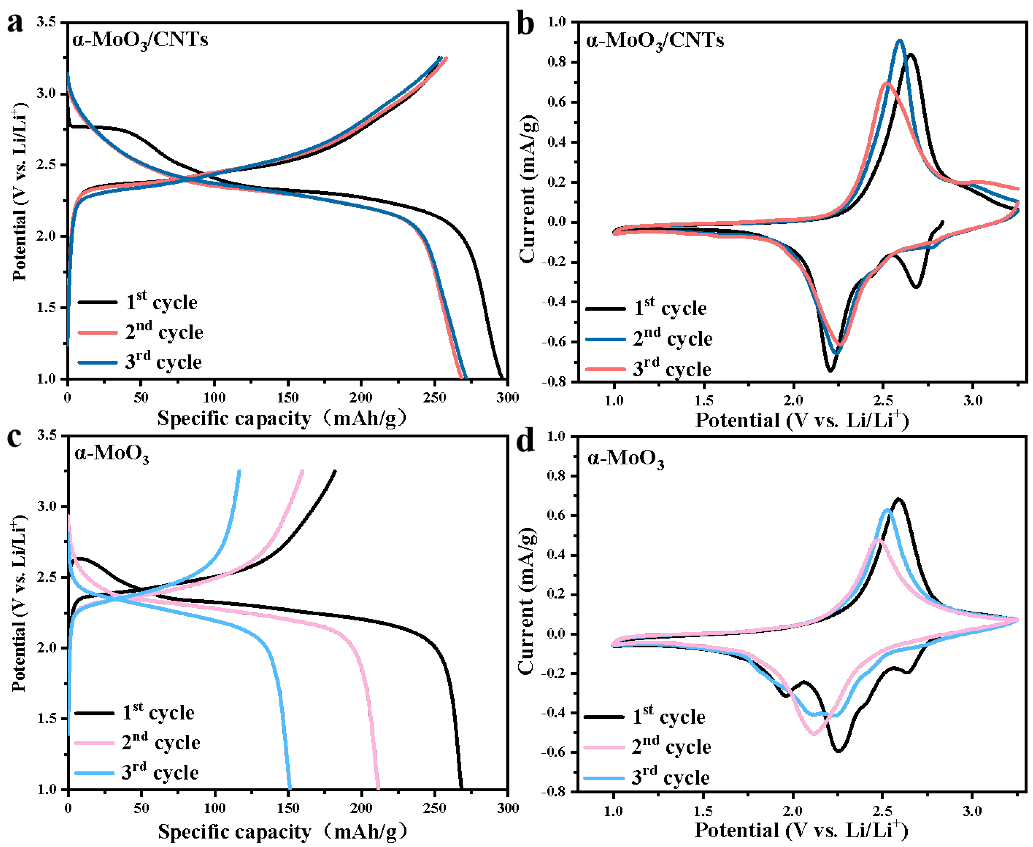
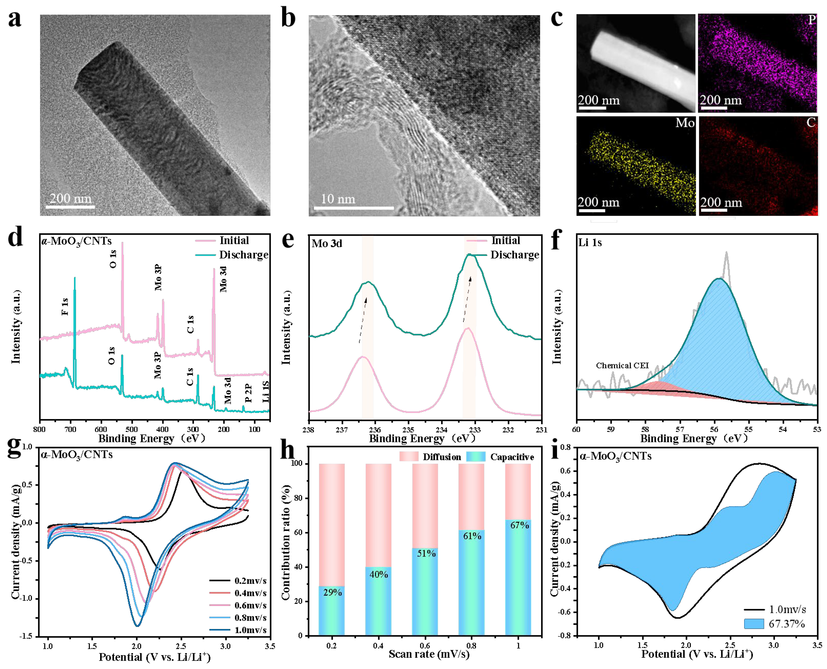
2.2. Electrochemical Analysis

To further study the effect of CNTs on α-MoO3 as a cathode material for lithium-ion batteries, the first three galvanostatic charge/discharge measurements of the α-MoO3/CNTs composite cathode and the pure α-MoO3 cathode were performed at a current density of 50 mA/g between the potential of 1 and 3.25 V. The results were contrasted with cases from the other work, as shown in Table 1. From the galvanostatic charge/discharge curves of the α-MoO3/CNTs composite cathode in Figure 3a, it can be seen that there was a discharge voltage plateau at about 2.75 V in the first cycle. The plateaus corresponded to Li+ intercalated in α-MoO3 to form a LixMoO3 solid solution, and these discharge plateaus disappeared in the subsequent cycles. The Li+ were reversibly intercalated and deintercalated in the α-MoO3/CNTs composite cathode, corresponding to the discharge voltage plateau at 2.25 V and the charging voltage plateau at 2.60 V, respectively. The initial discharge-specific capacity was 296 mAh/g, and the initial coulombic efficiency (ICE) reached 85%. The energy storage was primarily carried out by inserting and extracting Li+ by α-MoO3 in a composite cathode. In addition, the capacity of the pure α-MoO3 cathode without CNTs constantly decayed from Figure 3c, indicating that the α-MoO3/CNTs composite had better electrochemical performance. At the same current density, the first discharge-specific capacity of the pure α-MoO3 cathode was 268 mAh/g, but the first-coulomb efficiency was only 68%, which is probably the reason that the structure of pure α-MoO3 was irreversibly destroyed during the intercalation of Li+ [11,31]. In contrast, the structural failure of the α-MoO3/CNTs composite was caused by the volume expansion of α-MoO3 during Li+ storage [20]. Because of the embedding of CNTs, the α-MoO3 nanobelt in the α-MoO3/CNTs composite had a larger interlayer spacing, which provided more active sites of Li+ intercalation and deintercalation. Comparing the irreversible Li+ storage part of the α-MoO3/CNTs composite cathode with that of pure α-MoO3 by the galvanostatic charge/discharge curves, the lithium storage process of α-MoO3 by the Li+ intercalation and deintercalation of the [MoO6] octahedral inter-layers and intra-layers positions, as well as the irreversible Li+ storage, can be attributed to the Li+ intercalated in the α-MoO3 intra-layer positions, which could not be completely reversibly extracted [13,24]. The α-MoO3/CNTs composite cathode corresponded to only irreversible 0.23 Li+/Mo, while pure α-MoO3 corresponded to irreversible 0.45 Li+/Mo. The pure α-MoO3 corresponded to more irreversible Li+ ion intercalation, which further verifies the improvement of CNTs on the reversible Li+ ions storage part of α-MoO3. Comparing the cyclic voltammetry curves of the first three cycles at a scan rate of 0.2 mV/s of the α-MoO3/CNTs composite cathode with the pure α-MoO3 cathode, Figure 3b shows that the reduction peaks of the α-MoO3/CNTs composite cathode appeared at 2.7 and 2.2 V. However, the reduction peak at 2.7 V disappeared in the subsequent cycle, which was caused by the irreversible intercalation of Li+ into α-MoO3 in α-MoO3/CNTs composite cathode and the generation of the interface phase between the composite cathode and the electrolyte. The results correspond to the galvanostatic charge-discharge curve. As Figure 3d shows, the reduction peaks of the pure α-MoO3 cathode appeared at 2.6, 2.25, and 1.95 V, respectively, and then the peak position shifted significantly in the subsequent cycle, and the reduction peak appeared only at 2.1 V. These may have been due to the serious collapse of the layered structure of pure α-MoO3 cathode after the first Li+ insertion, and the reduction and instability of Li+ intercalation active sites between and within layers of pure α-MoO3 [32]. Compared with pure α-MoO3, the gap between the oxidation peak and the reduction peak was smaller, and the peak current was even larger in the CNTs added α-MoO3/CNTs composite cathode, indicating that the polarization phenomenon was smaller and the kinetic reaction was faster, respectively.
To explore the Li+ storage mechanism of the CNTs added to the α-MoO3/CNTs composite cathode, we characterized the morphology and elemental chemical state of the Li+ ion-intercalated α-MoO3/CNTs composite cathode after the first discharge. Figure 4a shows the TEM image of α-MoO3/CNTs first discharge to 1 V at a current density of 100 mA/g. It can be seen that the CNTs were uniformly distributed near the α-MoO3 nanobelts. The intercalation of Li+ during discharge increases the width of the α-MoO3 nanobelts of composite, according to previous studies [35]. It is worth noting that the Li+ intercalation composite cathode did not destroy the α-MoO3 crystal structure, and the surface remained smooth during the discharge process. This further illustrates that the lithium storage mechanism is the topological redox reaction, which is different from the mechanism of the α-MoO3/CNTs composite as the anode for the lithium-ion battery. When the α-MoO3/CNTs composite was used as an anode electrode for lithium storage in a voltage window of 0.01–3 V, a clear Li2O crystalline layer was observed on the surface of the α-MoO3 nanobelts, while no obvious Li2O crystalline layer was observed on the Li+ ion-intercalated α-MoO3/CNTs composite cathode after discharge [10]. Amplifying the edge position of the nanobelts in the Li+-intercalated α-MoO3/CNTs composite cathode, as shown in the HRTEM image of Figure 4b, both 3.64 Å lattice spacing corresponding to the (002) crystal plane of the bent CNTs and 2.07 Å lattice spacing corresponding to the (104) crystal plane of LixMoO3 (Li1.66Mo0.66O2) can be seen as a consequence of the insertion of Li+ ions into the α-MoO3 in the α-MoO3/CNTs composite. The element mapping image of Figure 4c indicates that the Mo and C elements from the α-MoO3/CNTs composite cathode, from the distribution of P element and EDS dark field image, can be further seen in the composite cathode Li+ ion storage primarily through the α-MoO3/CNTs composite cathode of α-MoO3. According to previous studies, when the α-MoO3/CNTs composite is used as an anode electrode, composite-intercalated Li+ converted into Mo and Li2O, and the Li+ ions’ deintercalation removed Li2MoO3 amorphous based on the conversion reaction [10,35,36]. In the subsequent cycle process, the reversible reaction between Mo and Li2O with Li2MoO3 occurs, which cannot return to the original α-MoO3/CNTs composite state, and more capacity loss occurs. Therefore, compared with the lithium storage mechanism of the topological redox reaction as the α-MoO3/CNTs composite cathode electrode of the lithium-ion battery, the first coulomb efficiency is lower when used as the anode electrode [9]. Figure 4d–f show the XPS images of the α-MoO3/CNTs composite cathode after the first discharge. Figure 4d XPS survey spectrum signifies the Mo, O, and C elements in the α-MoO3/CNTs composite, as well as Li, P, and F elements, from the intercalation of Li+ into the composite cathode during discharge and the generation of the interface phase between the composite cathode and the electrolyte. Compared with the initial α-MoO3/CNTs composite cathode, in the Mo3d high-resolution XPS spectrum (Figure 4f), after Li+ ions intercalation, the Mo 3d5/2 and Mo 3d3/2 of the discharged composites shifted to a small angle, which is attributed to the reaction:
MoO3 + xLi+ + xe ⟷ LixMoO3,
and to the formation of LixMoO3 [37,38,39]. Not only that, but the Li 1 s high-resolution XPS spectrum (Figure 4g), located in 54.9 eV and 56.7 eV, can be attributed to the formation of α-MoO3/CNTs composite cathode and electrolyte interface phases (CEI) and Li+ ions intercalation into the α-MoO3 layer of the formation.
The current study conducted cyclic voltammetry tests at different scan rates to explain the lithium storage mechanism of the CNTs added α-MoO3/CNTs composite cathode. As shown in Figure 4g–i, the CV curve presented that the redox peak position did not shift significantly, and the curve shape was almost unchanged as the scan rate increased, indicating a better rate performance. When the scan rate was greater than 0.6 mV/s, the charge storage was dominated by the capacitance and less limited by the diffusion-controlled redox reaction, indicating a greater Li+ transfer kinetic. And when the scan rate was 1.0 mV/s, the diffusion control was less than 32.7%. The α-MoO3/CNTs composite cathode will lead to faster reaction kinetics and an improved rate performance.
The rate capability and cycle performance of the α-MoO3/CNTs composite cathode are shown in Figure 5a,b. When the current density was 100 mA/g, the composite cathode had an initial specific capacity of 266 mAh/g. The α-MoO3/CNTs composite cathode with 168, 139, 122, 112, and 77 mAh/g of specific capacity at the current density increased to 200, 300, 400, 500, and 1000 mA/g, respectively, and when the current density returned to 100 mA/g, the composite cathode specific capacity returned to about 180 mAh/g. This demonstrates that the composite structure was hardly destroyed as the current density increased. Compared with the pure α-MoO3 cathode, when the current density was up to 1000 mA/g, the pure α-MoO3 cathode had almost no capacity. Furthermore, when the current density returned to the initial 100 mA/g, the pure α-MoO3 cathode specific capacity was much smaller than the initial specific capacity and was only 100 mAh/g. As a cathode electrode, CNTs hardly store Li+, but they effectively improve the Li+ reversible storage characteristics of α-MoO3 in the α-MoO3/CNTs composite and greatly improve the rate performance. Figure 5b shows the cycle performance of the α-MoO3/CNTs composite cathode and the pure α-MoO3 cathode at a current density of 100 mA/g. After 150 cycles, the α-MoO3/CNTs composite cathode still had a specific capacity of 93 mAh/g, while the pure α-MoO3 cathode had a specific capacity of only 34 mAh/g. The rate and cycle performance tests show that the capacity of the α-MoO3 cathode will decay rapidly during the initial cycle process, while it will be relatively stable during the subsequent cycles. This is because the intralayer sites of Li+ intercalation in α-MoO3 cannot be completely reversible during the initial charge-discharge process. With the gradual occupation of the intralayer sites, the irreversible storage of Li+ is improved [40]. The improvement of lithium storage electrochemical performance of α-MoO3 by CNTs in the composite cathode was proved; the CNTs embedded into nanobelts to enlarge the interlayer spacing of α-MoO3, and the three-dimensional conductive network of CNTs improved the poor conductivity and the structural failure caused by volume expansion of pure α-MoO3 during Li+ deintercalation.
To further explore the reason why CNTs improve the electrochemical performance of the α-MoO3/CNTs composite cathode, the Li+ diffusion kinetics of the composite cathode and pure α-MoO3 cathode during charging and discharging were investigated by the galvanostatic intermittent titration technique. As shown in Figure 5c,d, the diffusion coefficient of α-MoO3/CNTs composite cathode was always higher than that of the pure α-MoO3 cathode, which proves that Li+ diffused faster in the α-MoO3/CNTs composite cathode. This may have been due to the presence of the CNTs’ three-dimensional conductive network shortening the ion transport path. Meanwhile, we tested the electrochemical impedance spectroscopy for both the α-MoO3/CNTs composite cathode and pure α-MoO3 cathode in Figure 5e. It shows that compared to pure α-MoO3, the semicircle diameter of the α-MoO3/CNTs cathode in the high-frequency region was smaller, corresponding to the charge transfer resistance at the interface between the electrode and the electrolyte. The fitting circuit is shown in the upper left of Figure 5e (Rct = 53.33 Ω), and the enhanced conductivity indicates that the α-MoO3/CNTs composite cathode had a higher electron conduction efficiency and faster kinetic reaction. In Figure 5f, compared with pure α-MoO3, the α-MoO3/CNTs composite cathode had a smaller diffusion resistance (Warburg factor, Zw) in the low-frequency range, that is, the slope of the fitting curves of Z′ and ω−1/2 was smaller, which further verifies that the Li+ diffusion in the composite cathode was faster. The Li+ ion diffusion coefficient can be calculated according to the following formula:
D Li = R 2 T 2 2 A 2 n 4 F 4 C 2 σ 2
In Equation (2), DLi is the diffusion coefficient of Li+ (cm2/s), R is the gas constant (8.314 J/Kmol), T is the temperature during the experiment (298 K), A is the electrode material area (cm−2), n is the number of electrons per mole of the active material transferred in the electrode reaction, F is the Faraday constant (96,500 C/mol), C is the lithium ion concentration (mol/L), and σ is the slope of Z′~ω−1/2. The DLi = 9.3 × 10⁻¹⁹ cm2/s in the α-MoO3/CNTs composite cathode. The CNTs were embedded inside α-MoO3 nanobelts and cross-linked between α-MoO3 nanobelts, which improved the conductivity of the composite cathode and accelerated the transmission of Li+; it also effectively inhibited the volume expansion of α-MoO3 during charging and discharging. These tests show that the α-MoO3/CNTs composite cathode had faster electron and ion transfer rates and faster reaction kinetics.

3. Conclusions

In summary, the CNTs were added by the one-step hydrothermal reaction to synthesize the α-MoO3/CNTs composite and thus effectively solve the poor conductivity and cycle stability of pure α-MoO3. The part of CNTs was embedded inside the α-MoO3 nanobelts, which made the α-MoO3 have a larger interlayer spacing and provided more active sites and faster kinetic reaction for lithium storage. Another part of CNTs formed a three-dimensional conductive network between α-MoO3 nanobelts, enhancing the electrical conductivity of the composite, accelerating the electron conduction in the energy storage process, shortening the ion transport path, and alleviating the structural fragmentation caused by the volume expansion during the α-MoO3 deintercalation of Li+, leading to a significantly improved rate performance and cycle life of lithium storage.

Supplementary Materials

The following supporting information can be downloaded at: https://www.mdpi.com/article/10.3390/nano13152272/s1, Figure S1: XPS spectra of the α-MoO3/CNTs composite and pure α-MoO3: (a) Mo 3d, (b) O 1s region.; Figure S2: (a) N2 adsorption/desorption curve and (b) pore size distribution of the α-MoO3/CNTs.

Author Contributions

Formal analysis, X.L.; Resources, Q.Z.; Writing—review & editing, D.S., A.G. and Q.Z. All authors have read and agreed to the published version of the manuscript.

Funding

This project was financially supported by the Natural Science Foundation of Heilongjiang Province (Nos. HL2020A014 and ZD2009103), the National Natural Science Foundation of China (Nos. 22101163 and 52250710161), the Graduate Innovative Program of Harbin Normal University (No. HSDSSCX2022-53), and Key Laboratory of Engineering Dielectrics and Its Application (Harbin University of Science and Technology), Ministry of Education (KFM202005 and KF20171110).

Conflicts of Interest

The authors declare no conflict of interest.

References

  1. Larcher, D.; Tarascon, J.M. Towards greener and more sustainable batteries for electrical energy storage. Nat. Chem. 2015, 7, 19–29. [Google Scholar] [PubMed]
  2. Kang, B.; Ceder, G. Battery materials for ultrafast charging and discharging. Nature 2009, 458, 190–193. [Google Scholar] [CrossRef] [PubMed]
  3. Chernova, N.A.; Roppolo, M.; Dillon, A.C.; Whittingham, M.S. Layered vanadium and molybdenum oxides: Batteries and electrochromics. J. Mater. Chem. 2009, 19, 2526–2552. [Google Scholar]
  4. Hu, X.; Zhang, W.; Liu, X.; Mei, Y.; Huang, Y. Nanostructured Mo-based electrode materials for electrochemical energy storage. Chem. Soc. Rev. 2015, 44, 2376–2404. [Google Scholar]
  5. Mai, L.; Yang, F.; Zhao, Y.; Xu, X.; Xu, L.; Hu, B.; Luo, Y.; Liu, H. Molybdenum oxide nanowires: Synthesis & properties. Mater. Today 2011, 14, 346–353. [Google Scholar]
  6. Qu, G.; Wang, J.; Liu, G.; Tian, B.; Su, C.; Chen, Z.; Rueff, J.-P.; Wang, Z. Vanadium Doping Enhanced Electrochemical Performance of Molybdenum Oxide in Lithium-Ion Batteries. Adv. Funct. Mater. 2018, 29, 1805227. [Google Scholar] [CrossRef]
  7. Wang, Z.; Zhou, L.; Lou, X.W. Metal oxide hollow nanostructures for lithium-ion batteries. Adv. Mater. 2012, 24, 1903–1911. [Google Scholar] [CrossRef]
  8. Wang, X.-J.; Nesper, R.; Villevieille, C.; Novák, P. Ammonolyzed MoO3 Nanobelts as Novel Cathode Material of Rechargeable Li-Ion Batteries. Adv. Energy Mater. 2013, 3, 606–614. [Google Scholar] [CrossRef]
  9. Sheng, D.; Zhang, M.; Wang, X.; Zhou, S.; Fu, S.; Liu, X.; Zhang, Q. Carbon nanotubes embedded in α-MoO3 nanoribbons for enhanced lithium-ion storage. J. Mater. Sci. Mater. Electron. 2022, 33, 11743–11752. [Google Scholar] [CrossRef]
  10. Xia, W.; Zhang, Q.; Xu, F.; Sun, L. New Insights into Electrochemical Lithiation/Delithiation Mechanism of α-MoO3 Nanobelt by in Situ Transmission Electron Microscopy. ACS Appl. Mater. Interfaces 2016, 8, 9170–9177. [Google Scholar] [CrossRef]
  11. Zhang, H.; Liu, X.; Wang, R.; Mi, R.; Li, S.; Cui, Y.; Deng, Y.; Mei, J.; Liu, H. Coating of a-MoO3 on nitrogen-doped carbon nanotubes by electrodeposition as a high-performance cathode material for lithium-ion batteries. J. Power Sources 2015, 274, 1063–1069. [Google Scholar]
  12. Kim, H.-S.; Cook, J.B.; Lin, H.; Ko, J.S.; Tolbert, S.H.; Ozolins, V.; Dunn, B. Oxygen vacancies enhance pseudocapacitive charge storage properties of MoO3−x. Nat. Mater. 2017, 16, 454–460. [Google Scholar]
  13. Hu, Z.; Zhang, X.; Peng, C.; Lei, G.; Li, Z. Pre-intercalation of potassium to improve the electrochemical performance of carbon-coated MoO3 cathode materials for lithium batteries. J. Alloys Compd. 2020, 826, 154055. [Google Scholar]
  14. Ji, H.; Liu, X.; Liu, Z.; Yan, B.; Chen, L.; Xie, Y.; Liu, C.; Hou, W.; Yang, G. In Situ Preparation of Sandwich MoO3/C Hybrid Nanostructures for High-Rate and Ultralong-Life Supercapacitors. Adv. Funct. Mater. 2015, 25, 1886–1894. [Google Scholar] [CrossRef]
  15. Noerochim, L.; Wang, J.-Z.; Wexler, D.; Chao, Z.; Liu, H.-K. Rapid synthesis of free-standing MoO3/Graphene films by the microwave hydrothermal method as cathode for bendable lithium batteries. J. Power Sources 2016, 228, 198–205. [Google Scholar] [CrossRef] [Green Version]
  16. Xia, Q.; Zhao, H.; Du, Z.; Zeng, Z.; Gao, C.; Zhang, Z.; Du, X.; Kulka, A.; Świerczek, K. Facile synthesis of MoO3/carbon nanobelts as high-performance anode material for lithium ion batteries. Electrochim. Acta 2015, 180, 947–956. [Google Scholar]
  17. Dong, Y.; Li, S.; Xu, H.; Yan, M.; Xu, X.; Tian, X.; Liu, Q.; Mai, L. Wrinkled-graphene enriched MoO3 nanobelts with increased conductivity and reduced stress for enhanced electrochemical performance. Phys. Chem. Chem. Phys. 2013, 15, 17165–17170. [Google Scholar] [CrossRef] [PubMed]
  18. Greiner, M.T.; Chai, L.; Helander, M.G.; Tang, W.-M.; Lu, Z.-H. Transition metal oxide work functions: The influence of cation oxidation state and oxygen vacancies. Adv. Funct. Mater. 2012, 22, 4557–4568. [Google Scholar]
  19. Huang, L.; Yao, B.; Sun, J.; Gao, X.; Wu, J.; Wan, J.; Li, T.; Hu, Z.; Zhou, J. Highly conductive and flexible molybdenum oxide nanopaper for high volumetric supercapacitor electrode. J. Mater. Chem. 2017, 5, 2897–2903. [Google Scholar]
  20. Li, T.; Beidaghi, M.; Xiao, X.; Huang, L.; Hu, Z.; Sun, W.; Chen, X.; Gogotsi, Y.; Zhou, J. Ethanol reduced molybdenum trioxide for Li-ion capacitors. Nano Energy 2016, 26, 100–107. [Google Scholar] [CrossRef] [Green Version]
  21. Wang, W.; Qin, J.; Yin, Z.; Cao, M. Achieving Fully Reversible Conversion in MoO3 for Lithium Ion Batteries by Rational Introduction of CoMoO4. ACS Nano 2017, 16, 454–460. [Google Scholar]
  22. Mendoza-Sánchez, B.; Grant, P.S. Charge storage properties of a α-MoO3/carboxyl-functionalized single-walled carbon nanotube composite electrode in a Li ion electrolyte. Electrochim. Acta 2013, 98, 294–302. [Google Scholar]
  23. Zheng, Y.; Liu, Z.; Liu, B.; Wang, S.; Xiong, C. Fabrication of cactus-like CNT/SiO2/MoO3 ternary composites for superior lithium storage. Energy 2020, 11, 19. [Google Scholar]
  24. Hashem, A.M.; Groult, H.; Mauger, A.; Zaghib, K.; Julien, C.M. Electrochemical properties of nanofibers α-MoO3 as cathode materials for Li batteries. J. Power Sources 2012, 219, 126–132. [Google Scholar]
  25. Ramana, C.V.; Mauger, A.; Julien, C.M. Growth, characterization and performance of bulk and nanoengineered molybdenum oxides for electrochemical energy storage and conversion. Prog. Progress. Cryst. Growth Charact. Mater. 2021, 67, 100533. [Google Scholar]
  26. Zhang, H.; Wu, W.; Liu, Q.; Yang, F.; Shi, X.; Liu, X.; Yu, M.; Lu, X. Interlayer Engineering of α-MoO3 Modulates Selective Hydronium Intercalation in Neutral Aqueous Electrolyte. Angew. Chem. Int. Ed. Engl. 2021, 60, 896–903. [Google Scholar]
  27. Wang, Z.; Madhavi, S.; Lou, X.W. Ultralong α-MoO3 Nanobelts: Synthesis and Effect of Binder Choice on Their Lithium Storage Properties. J. Phys. Chem. C 2012, 116, 12508–12513. [Google Scholar]
  28. Yang, C.; Liu, X.; Yang, Z.; Gu, L.; Yu, Y. Improvement of lithium storage performance of molybdenum trioxide by a synergistic effect of surface coating and oxygen vacancies. Adv. Mater. Interfaces 2016, 3, 1600730. [Google Scholar] [CrossRef]
  29. Yang, W.; Xiao, J.; Ma, Y.; Cui, S.; Zhang, P.; Zhai, P.; Meng, L.; Wang, X.; Wei, Y.; Du, Z.; et al. Tin Intercalated Ultrathin MoO3 Nanoribbons for Advanced Lithium–Sulfur Batteries. Adv. Energy Mater. 2019, 9, 1803137. [Google Scholar] [CrossRef]
  30. Zhang, G.; Li, Y.; He, C.; Ren, X.; Zhang, P.; Mi, H. 2D Electrocatalysts: Recent Progress in 2D Catalysts for Photocatalytic and Electrocatalytic Artificial Nitrogen Reduction to Ammonia. Adv. Energy Mater. 2021, 11, 2170043. [Google Scholar]
  31. Zhao, G.; Zhang, L.; Sun, K. Capacitive contribution to lithium storage capacity in porous MoO3 films. J. Electroanal. Chem. 2013, 694, 61–67. [Google Scholar] [CrossRef]
  32. Yu, M.; Shao, H.; Wang, G.; Yang, F.; Liang, C.; Rozier, P.; Wang, C.-Z.; Lu, X.; Simon, P.; Feng, X. Interlayer gap widened α-phase molybdenum trioxide as high-rate anodes for dual-ion-intercalation energy storage devices. Nat. Commun. 2020, 11, 1348. [Google Scholar]
  33. Zhang, G.; Xiong, T.; Yan, M.; He, L.; Liao, X.; He, C.; Yin, C.; Zhang, H.; Mai, L. α-MoO3-x by plasma etching with improved capacity and stabilized structure for lithium storage. Nano Energy 2018, 49, 555–563. [Google Scholar] [CrossRef]
  34. Nadimicherla, R.; Chen, W.; Guo, X. Synthesis and characterization of α-MoO3 nanobelt composite positive electrode materials for lithium battery application. Mater Res. Bull. 2015, 66, 140–146. [Google Scholar] [CrossRef]
  35. Li, Y.; Sun, H.; Cheng, X.; Zhang, Y.; Zhao, K. In-situ TEM experiments and first-principles studies on the electrochemical and mechanical behaviors of α-MoO3 in Li-ion batteries. Nano Energy 2016, 27, 95–102. [Google Scholar] [CrossRef] [Green Version]
  36. Lee, S.-H.; Kim, Y.-H.; Deshpande, R.; Parilla, P.A.; Whitney, E.; Gillaspie, D.T.; Jones, K.M.; Mahan, A.H.; Zhang, S.; Dillon, A.C. Reversible lithium-ion insertion in molybdenum oxide nanoparticles. Adv. Mater. 2008, 08, 3627–3632. [Google Scholar] [CrossRef]
  37. Chen, M.; Zhang, Z.; Savilov, S.; Wang, G.; Chen, Z.; Chen, Q. Enhanced structurally stable cathodes by surface and grain boundary tailoring of Ni-Rich material with molybdenum trioxide. J. Power Sources 2020, 478, 229051. [Google Scholar] [CrossRef]
  38. Ette, P.M.; Babu, D.B.; Roy, M.L.; Ramesha, K. Mo3Nb2O14: A high-rate intercalation electrode material for Li-ion batteries with liquid and garnet based hybrid solid electrolytes. J. Power Sources 2019, 436, 226850. [Google Scholar] [CrossRef]
  39. Villevieille, C.; Gorzkowska-Sobas, A.; Fjellvåg, H.; Novák, P. Freeze-dryed LixMoO3 nanobelts used as cathode materials for lithium-ion batteries: A bulk and interface study. J. Power Sources 2015, 297, 276–282. [Google Scholar]
  40. Hashem, A.M.; Askar, M.H.; Winter, M.; Albering, J.H.; Besenhard, J.O. Electrical properties of polycrystalline TiO2· Thermoelectric power. Ionics 2007, 13, 155–162. [Google Scholar]
Figure 1. (a) Schematic of the comparison of α-MoO3/CNTs composite and pure α-MoO3. (b) XRD patterns of the α-MoO3/CNTs composite and pure α-MoO3. (c) SEM image of the α-MoO3/CNTs composite. (d) TEM image of the α-MoO3/CNTs composite. (e) XRD patterns around the (020), (040), and (060) diffraction peaks.
Nanomaterials 13 02272 g001
Figure 2. (a) Raman spectra of the α-MoO3/CNTs composite and pure α-MoO3. (b) TG and DTG curve of the α-MoO3/CNTs composite. (c) Survey XPS spectra of the α-MoO3/CNTs composite and pure α-MoO3. (d) The high-resolution XPS spectra of the C 1s region of the α-MoO3/CNTs composite.
Nanomaterials 13 02272 g002
Figure 3. (a) GCD curves of the α-MoO3/CNTs composite cathode. (b) CV curves of the α-MoO3/CNTs composite cathode. (c) GCD curves of the pure α-MoO3 cathode. (d) CV curves of the pure α-MoO3 cathode.
Nanomaterials 13 02272 g003
Figure 4. The Li+ ion-intercalated α-MoO3/CNTs composite cathode (a) TEM image, (b) HRTEM image, (c) EDS element images, (d) Survey XPS spectrum, (e) Mo 3d, and (f) Li 1s spectra. (g) CV curves of the α-MoO3/CNTs composite cathode were obtained. (h) The normalized charge contribution of the capacitive and diffusion-controlled capacities was extracted. (i) Capacitive charge storage contribution (blue area) to the total capacity at a scan rate of 1 mV/s.
Nanomaterials 13 02272 g004
Figure 5. (a) The rate capability of the α-MoO3/CNTs composite and pure α-MoO3 at different current densities. (b) Cycling performance of the α-MoO3/CNTs composite and pure α-MoO3 at 100 mA/g. GITT curve and diffusion coefficients calculated from GITT curves for (c) the α-MoO3/CNTs composite cathode and (d) pure α-MoO3 cathode. (e) Nyquist plots of the α-MoO3/CNTs composite and pure α-MoO3. (f) The relationship plots between Z’ and ω−1/2 in the low-frequency range of the α-MoO3/CNTs composite cathode.
Nanomaterials 13 02272 g005
Table 1. The literature data of the α-MoO3/carbon composite cathode.
CathodeInitial CapacityRate: Capability/Current
Density
Cycling LifeRef.
carbon-coated MoO3258 mA h g−1118 mAh g−1/3 A g−1125 mAh g−1 at 1.5 A g−1 after 500 cycles[13]
α-MoO3−x plasma etching224.2 mA h g−1≈90 mAh g−1/5 A g−167.3 mAh g−1 at 1 A g−1 after 1000 cycles[33]
α-MoO3/SWCNT-COOH193.8 mA h g−1--70 mAh g−1 at 0.5 A g−1
after 117 cycles
[22]
α-MoO3/N-CNTs250 mA h g−1190 mAh g−1/0.3 A g−1250 mAh g−1 at 0.3 A g−1 after 50 cycles[11]
α-MoO3/PEO352 mA h g−1--124 mAh g−1 at 0.03 A g−1 after 50 cycles[34]
This work296 mA h g−177.2 mAh g−1/1 A g−193 mAh g−1 at 0.1 A g−1
after 150 cycles
This work
Disclaimer/Publisher’s Note: The statements, opinions and data contained in all publications are solely those of the individual author(s) and contributor(s) and not of MDPI and/or the editor(s). MDPI and/or the editor(s) disclaim responsibility for any injury to people or property resulting from any ideas, methods, instructions or products referred to in the content.

