
Radio Frequency Identification Temperature/CO2 Sensor Using Carbon Nanotubes
 ,
,
Abstract
:1. Introduction
2. Materials and Methods
3. Results
4. Discussion
5. Conclusions
Author Contributions
Funding
Data Availability Statement
Conflicts of Interest
References
- Bolic, M.; Rostamian, M.; Djuric, P.M. Proximity Detection with RFID: A Step Toward the Internet of Things. IEEE Pervasive Comput. 2015, 14, 70–76. [Google Scholar] [CrossRef]
- Al-Fuqaha, A.; Guizani, A.M.; Mohammadi, M.; Aledhari, M.; Ayyash, M. Internet of Things: A Survey on Enabling Technologies, Protocols, and Applications. IEEE Commun. Surv. Tutor. 2015, 17, 2347–2376. [Google Scholar] [CrossRef]
- Gubbi, J.; Buyya, R.; Marusic, S.; Palaniswami, M. Internet of Things (IoT): A vision, architectural elements, and future directions. Future Gener. Comput. Syst. 2013, 29, 1645–1660. [Google Scholar] [CrossRef] [Green Version]
- Kaur, K. A Survey on Internet of Things—Architecture, Applications, and Future Trends. In Proceedings of the International Conference on Secure Cyber Computing and Communication (ICSCCC), Jalandhar, India, 15–17 December 2018; pp. 581–583. [Google Scholar]
- Datta, P.; Sharma, B. A survey on IoT architectures, protocols, security and smart city based applications. In Proceedings of the International Conference on Computing, Communication and Networking Technologies (ICCCNT), Delhi, India, 3–5 July 2017; pp. 1–5. [Google Scholar]
- Satti, J.; Habib, A.; Anam, H.; Zeb, S.; Amin, Y.; Loo, J.; Tenhunen, H. Miniaturized humidity and temperature sensing RFID enabled tags. Int. J. RF Microw. Comput.-Aided Eng. 2017, 28, e21151. [Google Scholar] [CrossRef]
- Islam, M.A.; Karmakar, N.C. Compact Printable Chipless RFID Systems. IEEE Trans. Microw. Theory Tech. 2015, 63, 3785–3793. [Google Scholar] [CrossRef]
- Genovesi, S.; Costa, F.; Monorchio, A.; Manara, G. Chipless RFID Tag Exploiting Multifrequency Delta-Phase Quantization Encoding. IEEE Antennas Wirel. Propag. Lett. 2016, 15, 738–741. [Google Scholar] [CrossRef]
- Aslam, B.; Khan, U.; Habib, A.; Amin, Y.; Tenhuunen, H. Frequency Signature Chipless RFID Tag With Enhanced Data Capacity. IEICE Electron. Express 2015, 12, 20150623. [Google Scholar] [CrossRef] [Green Version]
- Costa, F.; Genovesi, S.; Monorchio, A. Normalization-Free Chipless RFIDs by Using Dual-Polarized Interrogation. IEEE Trans. Microw. Theory Tech. 2016, 64, 310–318. [Google Scholar] [CrossRef]
- Shahid, L.; Shahid, H.; Riaz, M.A.; Naqvi, S.I.; Khan, M.S.; Amin, Y.; Loo, J. Chipless RFID Tag for Touch Event Sensing and Localization. IEEE Access 2020, 8, 502–513. [Google Scholar] [CrossRef]
- Chen, Y.; Liu, D.; Wang, S.; Li, Y.; Zhang, X. Self-powered smart active RFID tag integrated with wearable hybrid nanogenerator. Nano Energy 2019, 64, 103911. [Google Scholar] [CrossRef]
- Mumtaz, M.; Amber, S.; Ejaz, A.; Habib, A.; Jafri, I.; Amin, Y. Design and analysis of C shaped chipless RFID tag. In Proceedings of the International Symposium on Wireless Systems and Networks (ISWSN), Lahore, Pakistan, 19–22 November 2017; pp. 1–5. [Google Scholar]
- Athalye, A.; Savic, V.; Bolic, M.; Djuric, P.M. Novel Semi-Passive RFID System for Indoor Localization. IEEE Sens. 2013, 13, 528–537. [Google Scholar] [CrossRef] [Green Version]
- Amin, E.M.; Bhuiyan, M.S.; Karmakar, N.C.; Jensen, B.W. Development of a Low Cost Printable Chipless RFID Humidity Sensor. IEEE Sens. 2014, 14, 140–149. [Google Scholar] [CrossRef]
- Marindra, A.M.J.; Tian, G.Y. Chipless RFID Sensor Tag for Metal Crack Detection and Characterization. IEEE Trans. Microw. Theory Tech. 2018, 66, 2452–2462. [Google Scholar] [CrossRef]
- Zuffanelli, S.; Zamora, G.; Aguilà, P.; Paredes, F.; Martín, F.; Bonache, J. Analysis of the Split Ring Resonator (SRR) Antenna Applied to Passive UHF-RFID Tag Design. IEEE Trans. Antennas Propag. 2016, 64, 856–864. [Google Scholar] [CrossRef] [Green Version]
- Khan, M.M.; Tahir, F.A.; Farooqui, M.F.; Shamim, A.; Cheema, H.M. 3.56-bits/cm2 Compact Inkjet Printed and Application Specific Chipless RFID Tag. IEEE Antennas Wirel. Propag. Lett. 2016, 15, 1109–1112. [Google Scholar] [CrossRef]
- Colasanti, S.; Loghin, F.C.; Bhatt, V.D.; Abdellah, A.; Lugli, P.; Robbiano, V.; Cacialli, F. Experimental and computational study on the temperature behavior of CNT networks. In Proceedings of the International Conference on Nanotechnology (IEEE-NANO), Rome, Italy, 27–30 July 2015; pp. 1445–1448. [Google Scholar]
- Amin, E.M.; Karmakar, N.C. Development of a low cost printable humidity sensor for chipless RFID technology. In Proceedings of the International Conference on RFID-Technologies and Applications (RFID-TA), Nice, France, 5–7 November 2012; pp. 165–170. [Google Scholar]
- Noor, T.; Habib, A.; Amin, Y.; Loo, J.; Tenhunen, H. High-density chipless RFID tag for temperature sensing. High-density chipless RFID tag for temperature sensing. Electron. Lett. 2016, 52, 620–622. [Google Scholar] [CrossRef]
- Javed, N.; Habib, A.; Amin, Y.; Loo, J.; Akram, A.; Tenhunen, H. Directly Printable Moisture Sensor Tag for Intelligent Packaging. IEEE Sens. 2016, 16, 6147–6148. [Google Scholar] [CrossRef]
- Habib, A.; Asif, R.; Fawwad, M.; Amin, Y.; Loo, J.; Tenhunen, H. Directly Printable Compact Chipless RFID Tag for Humidity Sensing. IEICE Electron. Express 2017, 14, 20170169. [Google Scholar] [CrossRef] [Green Version]
- Eyebe, G.A.; Sama, N.; Boubekeur, N.; Domingue, F. Microwave sensing schemes of CPW resonators fully printed on humidity sensitive substrates. IEEE Microw. Wirel. Compon. Lett. 2019, 29, 303–305. [Google Scholar] [CrossRef]
- Martinez, M.; van der Weide, D. Circular polarization on depolarizing chipless RFID tags. In Proceedings of the IEEE Radio and Wireless Symposium (RWS), Austin, TX, USA, 24–27 January 2016; pp. 145–147. [Google Scholar]
- Habib, A.; Azam, M.A.; Amin, Y.; Tenhunen, H. Chipless slot resonators for IoT system identification. In Proceedings of the IEEE International Conference on Electro Information Technology (EIT), Grand Forks, ND, USA, 19–21 May 2016; pp. 0341–0344. [Google Scholar]
- Javed, N.; Habib, A.; Akram, A.; Amin, Y.; Tenhunen, H. 16-bit frequency signature directly printable tag for organic electronics. IEICE Electron. Express 2016, 13, 20160406. [Google Scholar] [CrossRef]
- Anam, H.; Habib, A.; Jafri, S.I.; Amin, Y.; Tenhunen, H. Directly printable frequency signatured chipless RFID tag for IoT applications. Radioengineering 2017, 26, 139–146. [Google Scholar] [CrossRef]
- Mihulowicz, J.; Weglarski, P.; Mariusz. Determination of passive and semi-passive chip parameters required for synthesis of interrogation zone in UHF RFID systems. Elektron. Elektrotech. 2014, 20, 65–73. [Google Scholar]
- Xu, L.; Huang, K. Design of compact trapezoidal bow-tie chipless RFID tag. Int. J. Antennas Propag. 2015, 7, 502938. [Google Scholar] [CrossRef] [Green Version]
- Javed, N.; Azam, M.A.; Qazi, I.; Amin, Y.; Tenhunen, H. Data-Dense Chipless RFID Multisensor for Aviculture Industry. IEEE Microw. Wirel. Compon. Lett. 2020, 30, 1193–1196. [Google Scholar] [CrossRef]
- Feng, Y. Printed RFID Humidity Sensor Tags for Flexible Smart Systems. Ph.D. Dissertation, KTH Royal Institute of Technology, Stockholm, Sweden, 2015. [Google Scholar]

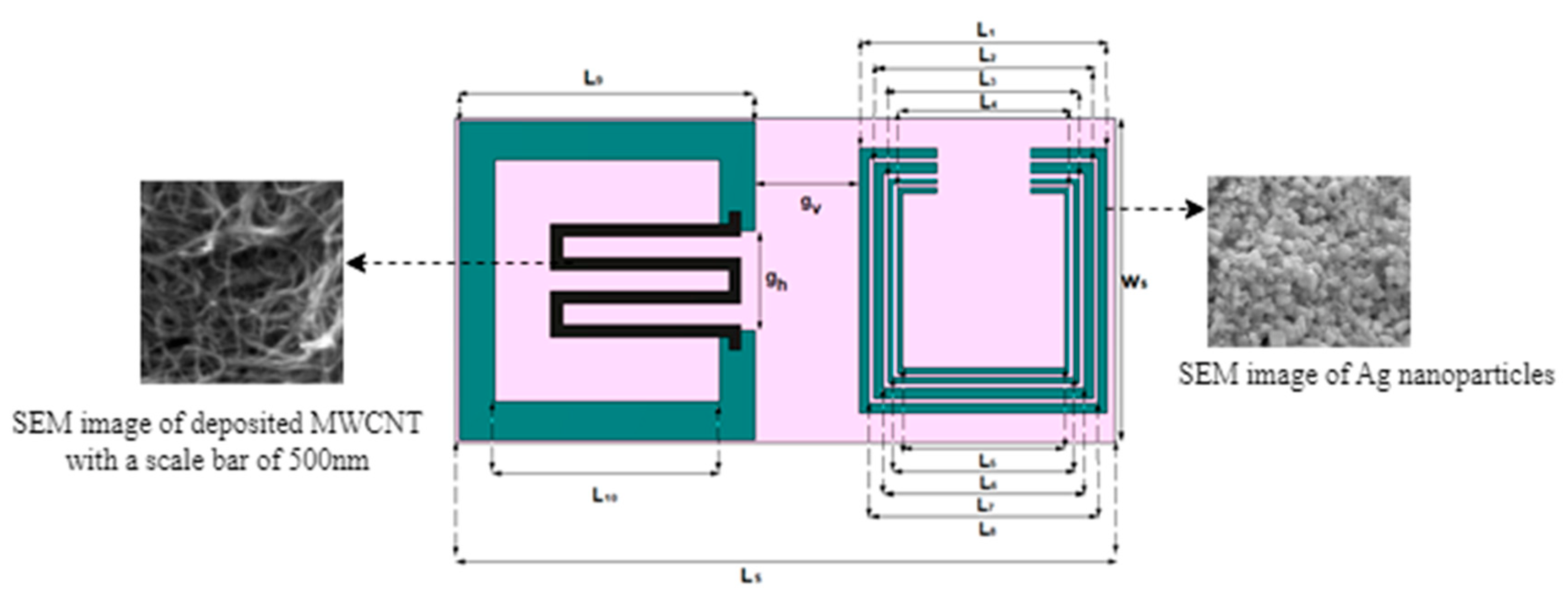
| Parameters | Value (mm) | Parameters | Value (mm) |
|---|---|---|---|
| Ls | 42.10 | L5 | 10.50 |
| Ws | 19.50 | L6 | 11.60 |
| L1 | 15.90 | L7 | 12.90 |
| L2 | 14.10 | L8 | 14.70 |
| L3 | 12.30 | L9 | 18.50 |
| L4 | 11.10 | L10 | 14.50 |
| gh | 7.00 | gv | 7.00 |
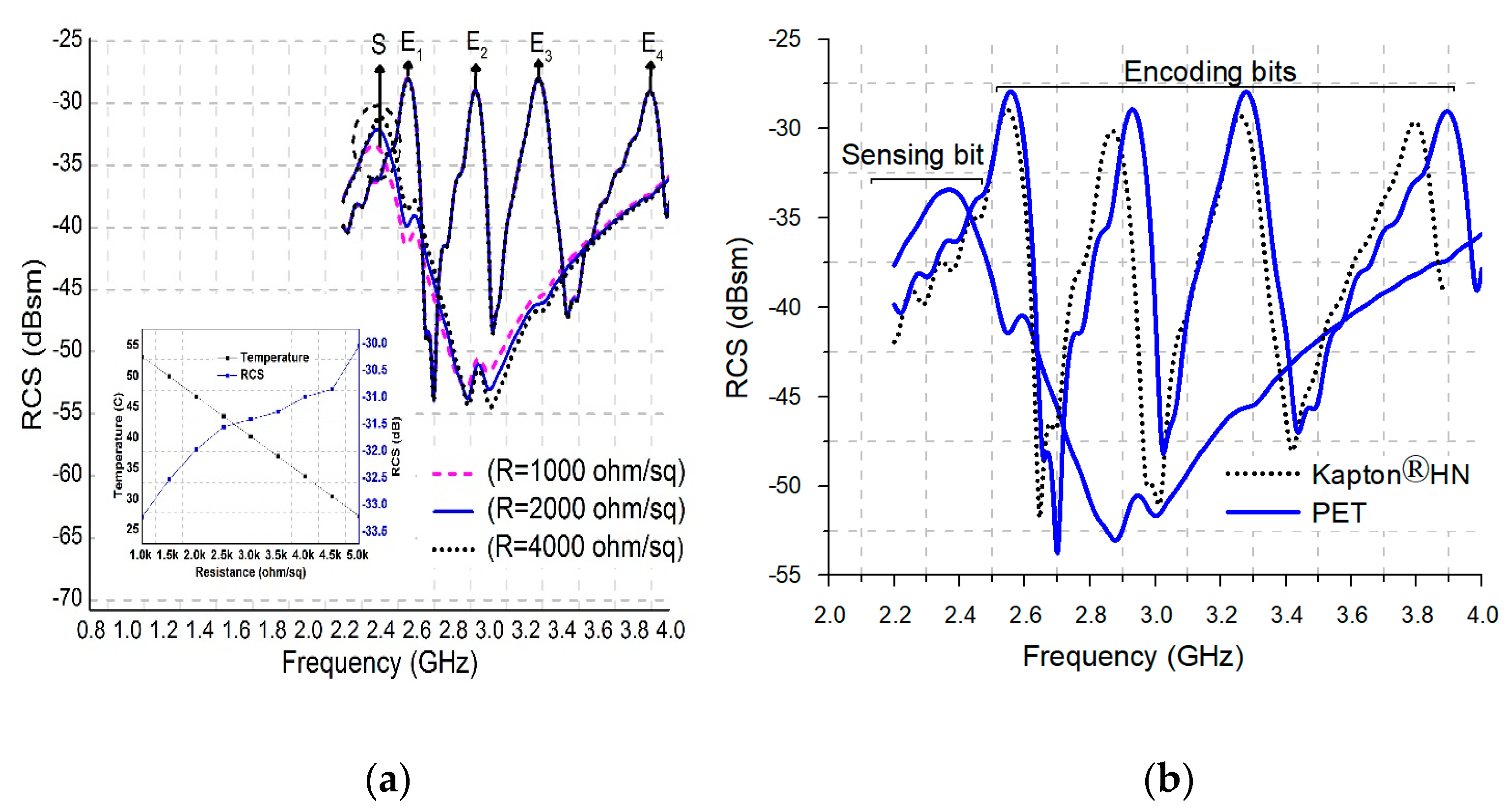
| Substrate | Kapton®HN | PET |
|---|---|---|
| Thickness (mm) | 0.125 | 0.100 |
| Frequency (GHz) | 3.8–2.28 | 3.9–2.36 |
| Bandwidth (GHz) | 1.52 | 1.54 |
| Conducting ink | silver | silver |
| Flexibility | √ | √ |
Disclaimer/Publisher’s Note: The statements, opinions and data contained in all publications are solely those of the individual author(s) and contributor(s) and not of MDPI and/or the editor(s). MDPI and/or the editor(s) disclaim responsibility for any injury to people or property resulting from any ideas, methods, instructions or products referred to in the content. |
© 2023 by the authors. Licensee MDPI, Basel, Switzerland. This article is an open access article distributed under the terms and conditions of the Creative Commons Attribution (CC BY) license (https://creativecommons.org/licenses/by/4.0/).
Share and Cite
Habib, A.; Akram, S.; Ali, M.R.; Muhammad, T.; Zainab, S.; Jehangir, S. Radio Frequency Identification Temperature/CO2 Sensor Using Carbon Nanotubes. Nanomaterials 2023, 13, 273. https://doi.org/10.3390/nano13020273
Habib A, Akram S, Ali MR, Muhammad T, Zainab S, Jehangir S. Radio Frequency Identification Temperature/CO2 Sensor Using Carbon Nanotubes. Nanomaterials. 2023; 13(2):273. https://doi.org/10.3390/nano13020273
Chicago/Turabian StyleHabib, Ayesha, Safia Akram, Mohamed R. Ali, Taseer Muhammad, Sajeela Zainab, and Shafia Jehangir. 2023. "Radio Frequency Identification Temperature/CO2 Sensor Using Carbon Nanotubes" Nanomaterials 13, no. 2: 273. https://doi.org/10.3390/nano13020273