
Study on Thermal Effect of Aluminum-Air Battery
 , and
, and
Abstract
:1. Introduction
2. Experimental
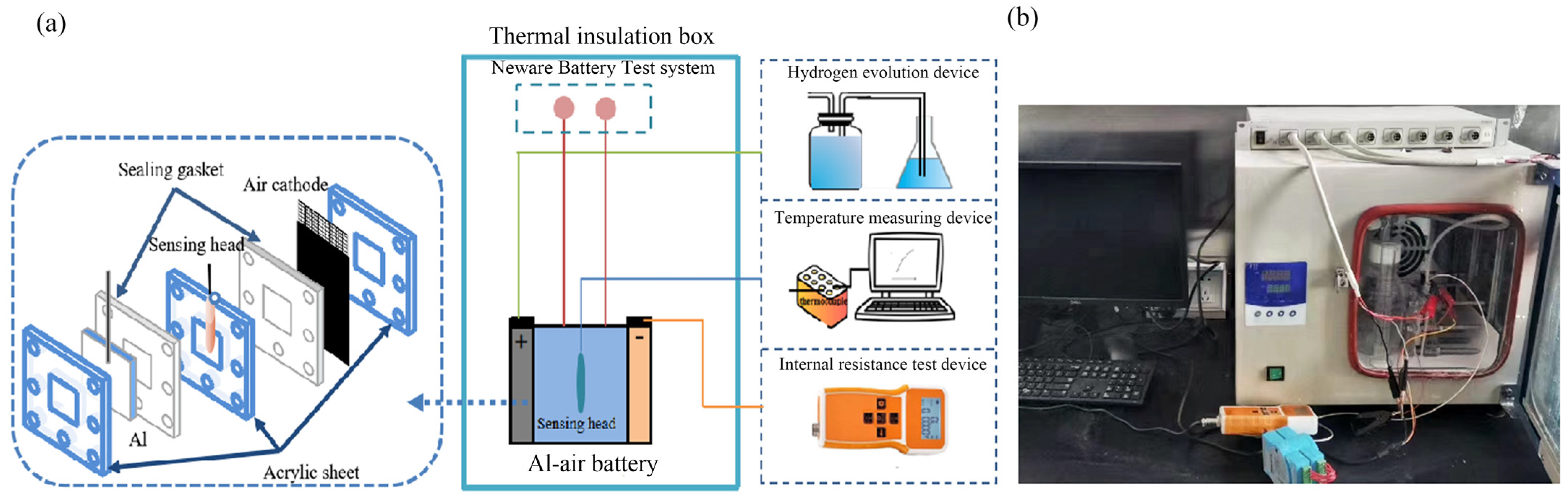
2.1. Construction of Thermal Effect Test System
2.2. Hydrogen-Evolution Test
2.3. Internal Resistance Test of Battery
2.4. Specific Heat Capacity Test of the Electrolyte
2.5. Electrolyte Additives
3. Results and Discussion
3.1. Composition of Heat Release during the Discharge Process
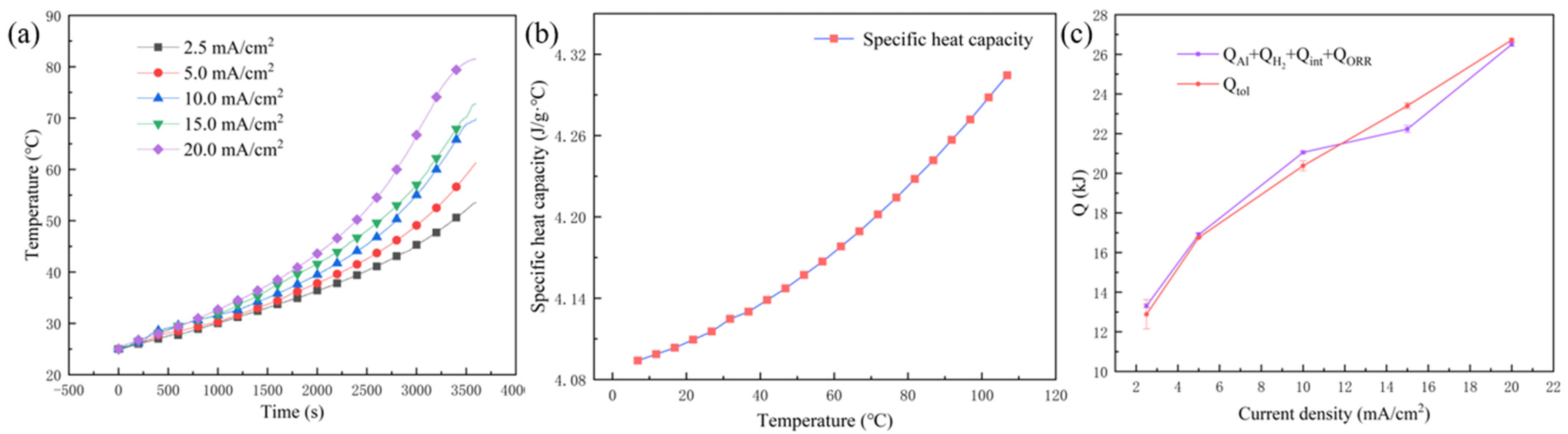
3.1.1. Qtol
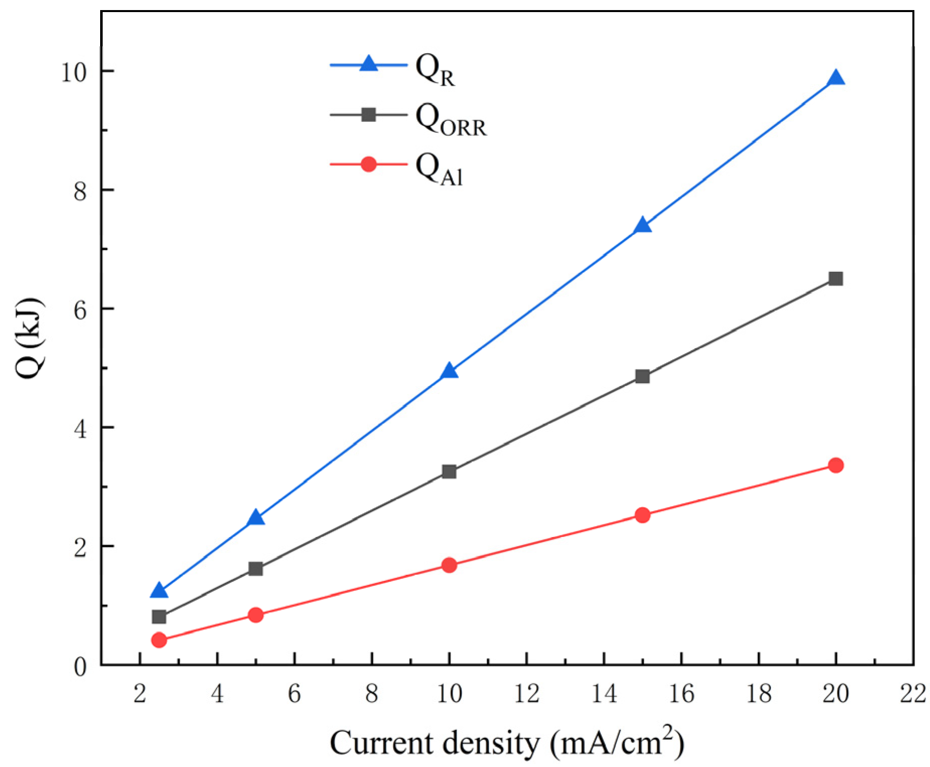
3.1.2. QR
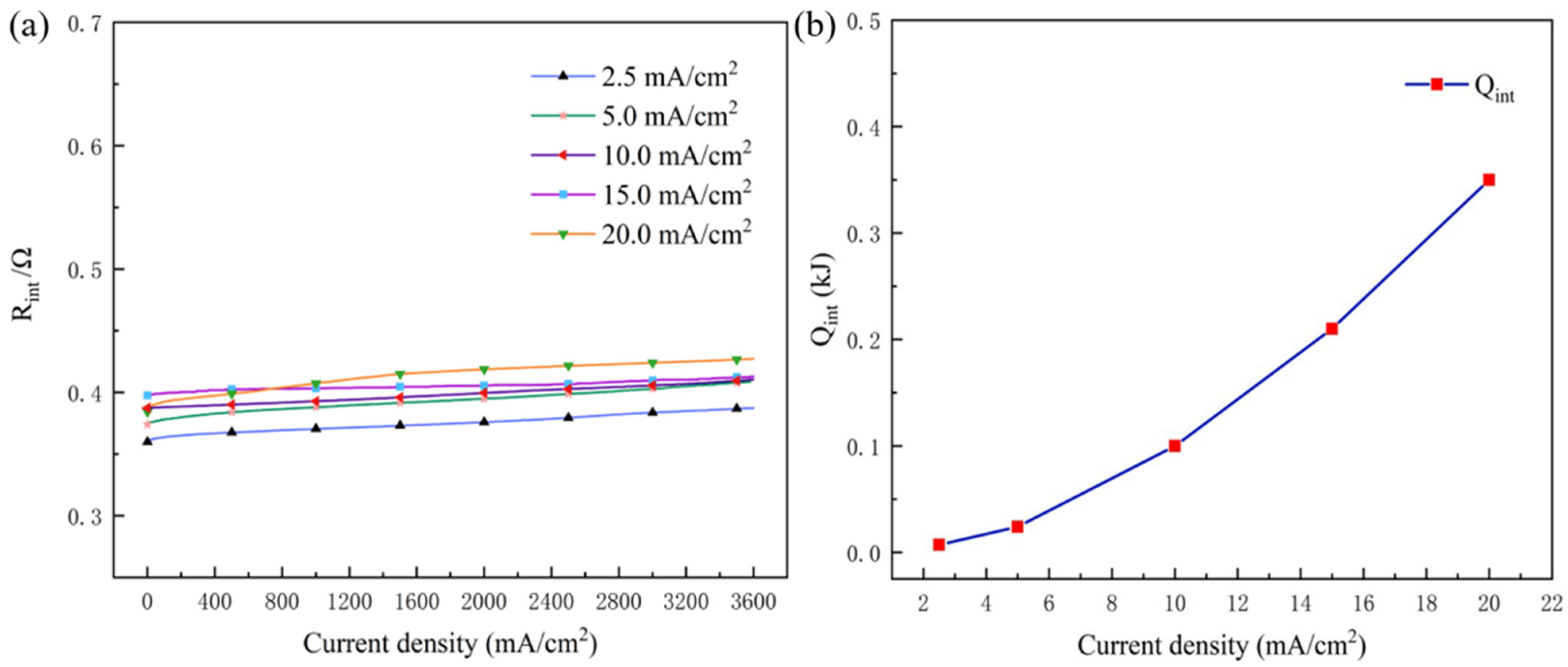
3.1.3. QJ and QP
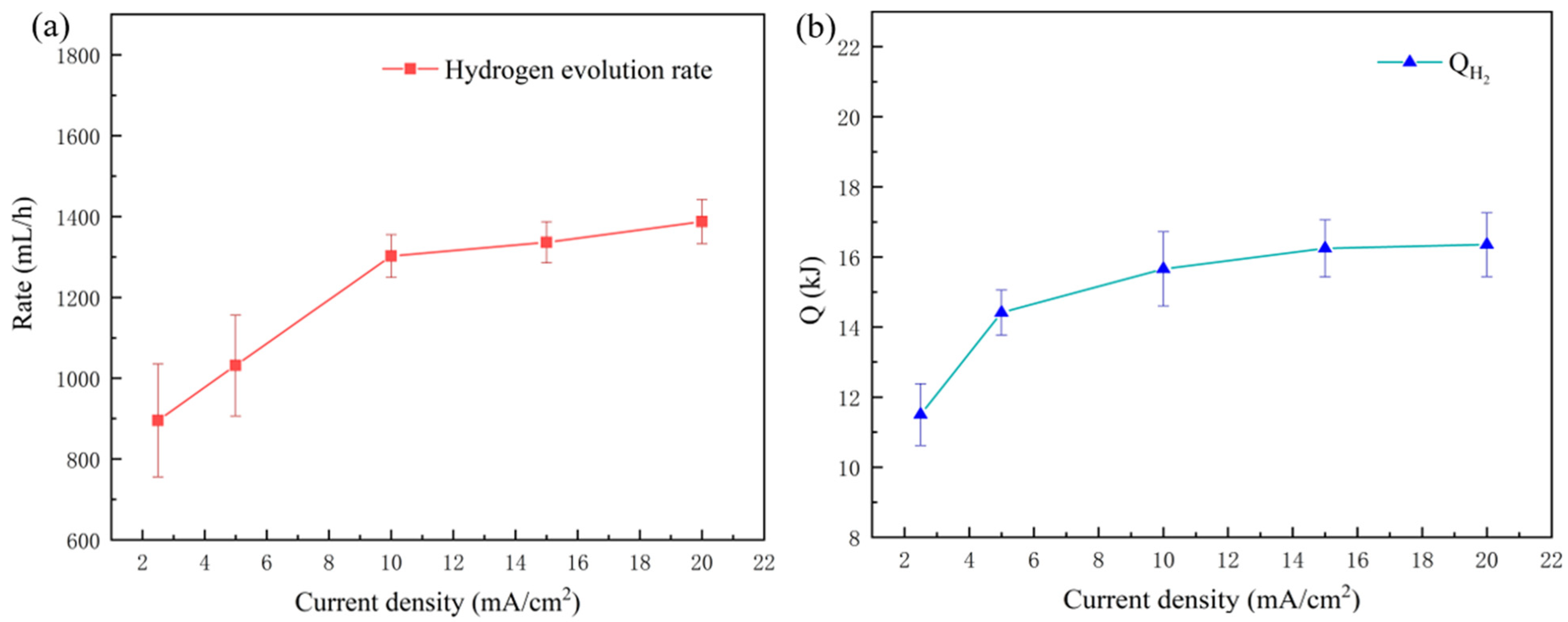
3.1.4. QH2
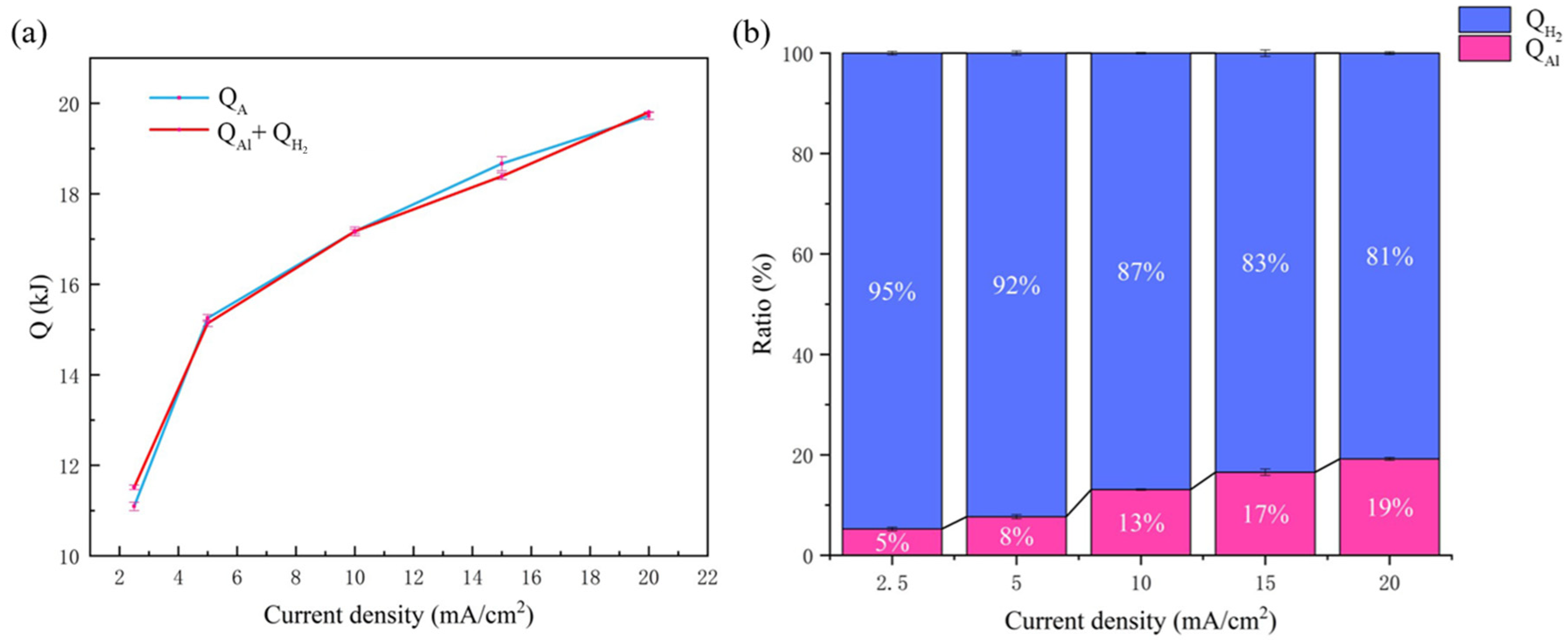
3.1.5. QA
3.2. Quantitative Analysis for Heat Generated by Each Part
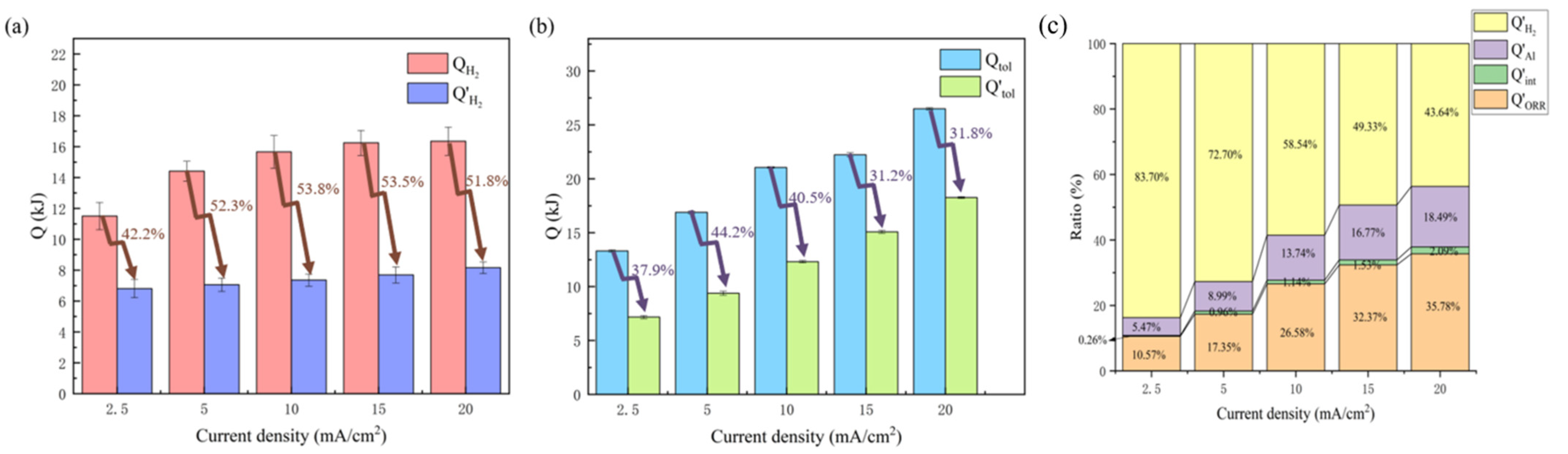
3.3. Regulating the Thermal Effect of the Aluminum–Air Battery
4. Conclusions
- (1)
- The thermal effect of an aluminum-air battery was investigated to provide a theoretical model by combining experimental measurement and mathematical calculation. The generated heat during the discharge process (Qtol) was divided into the following parts: aluminum oxidation reaction heat at the anode (QAl), oxygen reduction reaction at the cathode (QORR), heat production against the battery’s internal resistance (Qint, sum of QJ and QP), and the hydrogen-evolution heat (QH2).
- (2)
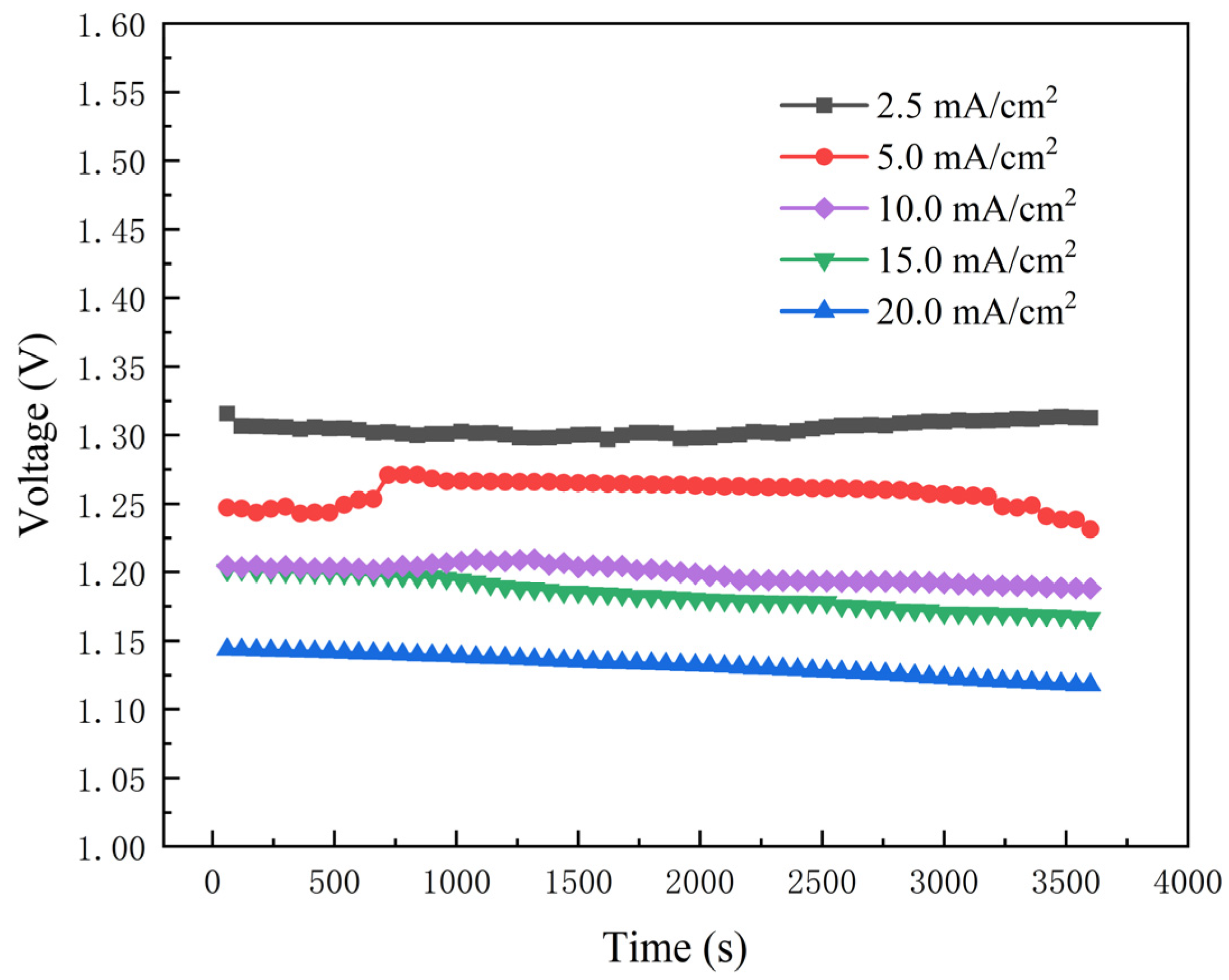
- The heat of each part noted above was quantitatively analyzed with different discharge rates. It could be shown that all heat production increased with the increase in current density, accelerating the rise in temperature of the battery. Obviously, the battery became more unstable at high discharge rates, resulting in thermal runaway in a short period.
- (3)
- Hydrogen-evolution heat (QH2) accounted for most of the total heat, more than 60% and up to 90% at the low discharge rate of 2.5 mA/cm2. It can be concluded that QH2 plays the dominant role in thermal effect during the discharge process of the battery. The hydrogen-evolution reaction should be inhibited to avoid thermal runaway of the battery.
- (4)
- Hybrid additives of DTAB and ZnO were introduced into the electrolyte to inhibit the hydrogen-evolution reaction at the aluminum electrode. The hydrogen-evolution rate was greatly reduced, lowering its contributed heat by more than 50% and its portion in Qtol. This also provides an effective way to solve the crucial challenge of battery thermal runaway.
Author Contributions
Funding
Data Availability Statement
Conflicts of Interest
References
- Hopkins, B.J.; Shao-Horn, Y.; Hart, D.P. Suppressing corrosion in primary aluminum air batteries via oil displacement. Science 2018, 362, 658–661. [Google Scholar] [CrossRef]
- Luan, J.; Zhang, Q.; Yuan, H.; Sun, D.; Peng, Z.; Tang, Y.; Ji, X.; Wang, H. Plasmalogtrengthened lithiophilicity of copper oxide nanosheet-decorated Cu foil for stable lithium metal anode. Adv. Sci. 2019, 6, 1901433. [Google Scholar] [CrossRef]
- Wu, Z.; Zhang, H.; Zou, J.; Shen, X.; Qin, K.; Ban, C.; Cui, J.; Nagaumi, H. Enhancement of the discharge performance of Al-0.5Mg-0.1Sn-0.05Ga (wt.%) anode for Al-air battery by directional solidification technique and subsequent rolling process. J. Alloys Compd. 2020, 827, 154272. [Google Scholar] [CrossRef]
- Li, F.; Li, J.; Feng, Q.; Yan, J.; Tang, Y.; Wang, H. Significantly enhanced oxygen reduction activity of Cu/CuNxCy co-decorated ketjenblack catalyst for Al-air batteries. J. Energy Chem. 2018, 27, 419–425. [Google Scholar] [CrossRef]
- Wang, H.; Leung, D.; Leung, M. Energy analysis of hydrogen and electricity production from aluminum-based processes. Appl. Energy 2012, 90, 100–105. [Google Scholar] [CrossRef]
- Driscoll, C.T.; Schecher, W.D. The chemistry of aluminum in the environment. Environ. Geochem. Health 1990, 12, 28–49. [Google Scholar] [CrossRef] [PubMed]
- Rahman, M.A.; Wang, X.J.; Wen, C.E. High Energy Density Metal-Air Batteries: A Review. J. Electrochem. Soc. 2013, 160, A1759. [Google Scholar] [CrossRef]
- Buckingham, R.; Asset, T.; Atanassov, P. Aluminum-air batteries: A review of alloys, electrolytes and design. J. Power Sources 2021, 498, 229762. [Google Scholar] [CrossRef]
- Mauger, A.; Julien, C.M.; Paolella, A.; Armand, M.; Zaghib, K. A comprehensive review of lithium salts and beyond for rechargeable batteries: Progress and perspectives. Mater. Sci. Eng. R Rep. 2018, 134, 1–21. [Google Scholar] [CrossRef]
- Nestoridi, M.; Pletcher, D.; Wood, R.; Wang, S.; Jones, R.L.; Stokes, K.R. The study of aluminium anodes for high power density al/air batteries with brine electrolytes. J. Power Sources 2007, 178, 445–455. [Google Scholar] [CrossRef] [Green Version]
- Wang, Y.F.; Kwok, H.Y.H.; Pan, W.D.; Zhang, H.M.; Lu, X.; Leung, D.Y.C. Parametric study and optimization of a low-cost paper-based Al-air battery with corrosion inhibition ability. Appl. Energy 2019, 251, 113342. [Google Scholar] [CrossRef]
- Shim, J.; Kostecki, R.; Richardson, T.; Song, X.; Striebel, K. Electrochemical analysis for cycle performance and capacity fading of a lithium-ion battery cycled at elevated temperature. J. Power Sources 2002, 112, 222–230. [Google Scholar] [CrossRef]
- Coman, P.T.; Darcy, E.C.; Veje, C.T.; White, R.E. Numerical analysis of heat propagation in a battery pack using a novel technology for triggering thermal runaway. Appl. Energy 2017, 203, 189–200. [Google Scholar] [CrossRef]
- Kvasha, A.; Gutiérrez, C.; Osa, U.; Meatza, I.D.; Blazquez, J.A.; Macicior, H.; Urdampilleta, I. A comparative study of thermal runaway of commercial lithium-ion cells. Energy 2018, 159, 547–557. [Google Scholar] [CrossRef]
- Sato, N. Thermal behavior analysis of lithium-ion batteries for electric and hybrid vehicles. J. Power Sources 2001, 99, 70–77. [Google Scholar] [CrossRef]
- Wang, Q.; Jiang, B.; Li, B.; Yan, Y.Y. A critical review of thermal management models and solutions of lithium-ion batteries for the development of pure electric vehicles. Renew. Sustain. Energy Rev. 2016, 64, 106–128. [Google Scholar] [CrossRef]
- Liu, H.; Wei, Z.; He, W.; Zhao, J. Thermal issues about li-ion batteries and recent progress in battery thermal management systems: A review. Energy Convers. Manag. 2017, 150, 304–330. [Google Scholar] [CrossRef]
- Jiang, F.M.; Peng, P.; Sun, Y.Q. Thermal analyses of LiFePO4 /graphite battery discharge processes. J. Power Sources 2013, 243, 181–194. [Google Scholar] [CrossRef]
- Pan, D.; Guo, H.; Tang, S.; Li, X.; Wang, Z.; Peng, W.; Wang, J.; Yan, G. Evaluating the accuracy of electro-thermal coupling model in lithium-ion battery via altering internal resistance acquisition methods. J. Power Sources 2020, 463, 228174. [Google Scholar] [CrossRef]
- Chatterjee, K.; Majumdar, P.; Schroeder, D.; Kilaparti, S.R. Performance analysis of Li-ion battery under various thermal and load conditions. J. Electrochem. Energy 2019, 16, 021006. [Google Scholar] [CrossRef]
- Bernadi, D.; Pawlikowski, E.; Newman, J. A general energy balance for battery systems. J. Electrochem. Soc. 1985, 132, 5–12. [Google Scholar] [CrossRef]
- Chen, L.D.; Nørskov, J.K.; Luntz, A.C. Al-air batteries: Fundamental thermodynamic limitations from first-principles theory. J. Phys. Chem. Lett. 2014, 6, 175–179. [Google Scholar] [CrossRef]
- Nyman, A.; Zavalis, T.G.; Elger, R.; Behm, M.; Lindbergh, G. Analysis of the Polarization in a Li-Ion Battery Cell by Numerical Simulations. J. Electrochem. Soc. 2010, 157, A1236–A1246. [Google Scholar] [CrossRef]
- Zhang, P.; Liu, X.; Xue, J.; Wang, Z. Evaluating the discharge performance of heat-treated Al-Sb alloys for al-air batteries. J. Mater. Eng. Perform. 2019, 28, 5476–5484. [Google Scholar] [CrossRef]
- Pk, A.; Vm, B.; Cp, B.; Ga, A.; Pl, C. Study of some basic operation conditions of an al-air battery using technical grade commercial aluminum. J. Power Sources 2020, 450, 227624. [Google Scholar]
- Wang, D.; Li, H.; Liu, J.; Zhang, D.; Gao, L.; Tong, L. Evaluation of AA5052 alloy anode in alkaline electrolyte with organic rare-earth complex additives for aluminium-air batteries. J. Power Sources 2015, 293, 484–491. [Google Scholar] [CrossRef]
- Xiong, H.; Wang, Z.; Yu, H.; Chen, T.; Ye, L. Performances of al-xli alloy anodes for al-air batteries in alkaline electrolyte. J. Alloys Compd. 2021, 889, 161677. [Google Scholar] [CrossRef]
- Gaele, M.F.; Migliardini, F.; Palma, T.M.D. Dual solid electrolytes for aluminium-air batteries based on polyvinyl alcohol acidic membranes and neutral hydrogels. J. Solid State Electrochem. 2021, 25, 1207–1216. [Google Scholar] [CrossRef]
- Wu, Z.; Zhang, H.; Yang, D.; Zou, J.; Qin, K.; Ban, C.; Cui, J.; Nagaumi, H. Electrochemical behaviour and discharge characteristics of an Al-Zn-In-Sn anode for Al-air batteries in an alkaline electrolyte. J. Alloys Compd. 2020, 837, 155599. [Google Scholar] [CrossRef]
- Pastor-Fernandez, C.; Uddin, K.; Chouchelamane, G.H.; Widanage, W.D.; Marco, J. Dataset to support: “A comparison between electrochemical impedance spectroscopy and incremental capacity-differential voltage as li-ion diagnostic techniques to identify and quantify the effects of degradation modes within battery management systems”. J. Power Sources 2017, 360, 301–318. [Google Scholar] [CrossRef]
- Yang, X.G.; Zhang, G.; Wang, C.Y. Computational design and refinement of self-heating lithium-ion batteries. J. Power Sources 2016, 328, 203–211. [Google Scholar] [CrossRef]
- Smith, J.M.; Ness, V.; Abbott, M.M. Introduction to Chemical Engineering Thermodynamics; McGraw-Hill: New York, NY, USA, 2001; pp. 476–509. [Google Scholar]
- Fan, Y.X.; Yan, G.; Zou, H.Q.; Fu, J. Development of real-time simulation application software for four-quadrant converter system based on matlab. Int. J. Softw. Eng. Knowl. Eng. 2018, 28, 523–535. [Google Scholar] [CrossRef]
- Wang, D.P.; Zhang, D.Q.; Lee, K.Y.; Gao, L.X. Performance of AA5052 alloy anode in alkaline ethylene glycol electrolyte with dicarboxylic acids additives for aluminium air batteries. J. Power Sources 2015, 297, 464–471. [Google Scholar] [CrossRef]
- Jingling, M.; Jiuba, W.; Hongxi, Z.; Quanan, L. Electrochemical performances of Al–0.5Mg–0.1Sn–0.02In alloy in different solutions for Al–air battery. J. Power Sources 2015, 293, 592–598. [Google Scholar] [CrossRef]
- Ryu, J.; Park, M.; Cho, J. Advanced technologies for high-energy aluminum-air batteries. Adv. Mater. 2019, 31, 1804784. [Google Scholar] [CrossRef]


| Substance | ∆fHmθ (298 K) (kJ·mol−1) | Cp,m (J·deg−1·mol−1) |
|---|---|---|
| Al | 0 | 24.4 |
| H2O | −285.83 | 37.11 |
| OH− | −230.015 | −148.5 |
| H2 | 0 | 28.84 |
| Al(OH)4− | −1502.5 | 5.12 * |
| Al3+ | −538.4 | 3.98 * |
| O2 | 0 | 0.92 |
| Current Density/mA·cm−1 | QR/kJ | QAl/kJ | QORR/kJ | QH2/kJ | Qtol/kJ | Qint/kJ | QA/kJ | QAl + QH2/kJ | QAl + QORR QH2 + Qint/kJ |
|---|---|---|---|---|---|---|---|---|---|
| 2.5 | 1.23 | 0.42 | 0.81 | 11.13 ± 0.88 | 13.38 ± 0.09 | 0.007 | 11.03 ± 0.20 | 11.55 ± 0.88 | 12.36 ± 0.88 |
| 5 | 2.46 | 0.84 | 1.62 | 14.25 ± 0.64 | 16.98 ± 0.12 | 0.024 | 15.31 ± 0.16 | 15.09 ± 0.64 | 16.74 ± 0.64 |
| 10 | 4.93 | 1.68 | 3.25 | 15.52 ± 1.05 | 21.01 ± 0.06 | 0.10 | 17.24 ± 0.17 | 17.20 ± 1.05 | 20.55 ± 1.05 |
| 15 | 7.38 | 2.52 | 4.86 | 15.92 ± 0.81 | 22.36 ± 0.18 | 0.21 | 18.78 ± 0.24 | 18.44 ± 0.81 | 23.51 ± 0.81 |
| 20 | 9.86 | 3.36 | 6.50 | 16.45 ± 0.91 | 26.43 ± 0.09 | 0.35 | 19.78 ± 0.13 | 19.81 ± 0.91 | 26.66 ± 0.91 |
| Current Density/mA·cm−1 | 2.5 | 5 | 10 | 15 | 20 |
|---|---|---|---|---|---|
| RH2/mL·cm−2·h−1 | 947.90 ± 81.30 | 1168.72 ± 78.41 | 1257.48 ± 52.74 | 1289.40 ± 50.84 | 1332.20 ± 54.52 |
| Rint/Ω | 0.3752 ± 0.0121 | 0.3982 ± 0.0124 | 0.4055 ± 0.0074 | 0.4138 ± 0.0134 | 0.5063 ± 0.0296 |
| ∆T/°C | 28.62 ± 2.10 | 36.35 ± 1.32 | 44.90 ± 1.89 | 47.80 ± 2.31 | 56.50 ± 1.54 |
| ∆mAl/g | 0.55 ± 0.02 | 0.77 ± 0.01 | 0.87 ± 0.01 | 0.94 ± 0.03 | 0.99 ± 0.01 |
| Current Density/mA cm−1 | 2.5 | 5 | 10 | 15 | 20 |
|---|---|---|---|---|---|
| R’H2/mL·h−1 | 445.23 ± 39.30 | 478.76 ± 45.63 | 522.74 ± 34.34 | 552.40 ± 52.21 | 610.23 ± 34.52 |
| Q’H2/kJ | 6.43 ± 0.59 | 6.79 ± 0.43 | 7.16 ± 0.39 | 7.41 ± 0.51 | 17.93 ± 0.38 |
| Q’tol/kJ | 7.68 ± 0.14 | 9.34 ± 0.18 | 12.23 ± 0.10 | 15.02 ± 0.14 | 18.17 ± 0.09 |
Disclaimer/Publisher’s Note: The statements, opinions and data contained in all publications are solely those of the individual author(s) and contributor(s) and not of MDPI and/or the editor(s). MDPI and/or the editor(s) disclaim responsibility for any injury to people or property resulting from any ideas, methods, instructions or products referred to in the content. |
© 2023 by the authors. Licensee MDPI, Basel, Switzerland. This article is an open access article distributed under the terms and conditions of the Creative Commons Attribution (CC BY) license (https://creativecommons.org/licenses/by/4.0/).
Share and Cite
Cai, Y.; Tong, Y.; Liu, Y.; Li, X.; Chen, B.; Liu, F.; Zhou, B.; Liu, Y.; Qin, Z.; Wu, Z.; et al. Study on Thermal Effect of Aluminum-Air Battery. Nanomaterials 2023, 13, 646. https://doi.org/10.3390/nano13040646
Cai Y, Tong Y, Liu Y, Li X, Chen B, Liu F, Zhou B, Liu Y, Qin Z, Wu Z, et al. Study on Thermal Effect of Aluminum-Air Battery. Nanomaterials. 2023; 13(4):646. https://doi.org/10.3390/nano13040646
Chicago/Turabian StyleCai, Yajun, Yunwei Tong, Yingjie Liu, Xinyu Li, Beiyang Chen, Feng Liu, Baowei Zhou, Yichun Liu, Zhenbo Qin, Zhong Wu, and et al. 2023. "Study on Thermal Effect of Aluminum-Air Battery" Nanomaterials 13, no. 4: 646. https://doi.org/10.3390/nano13040646