
Ni-Based Molecular Sieves Nanomaterials for Dry Methane Reforming: Role of Porous Structure and Active Sites Distribution on Hydrogen Production

 ,
,  ,
,  , , and
Abstract
:1. Introduction
2. Materials and Methods
2.1. Materials
2.2. Catalyst Preparation
2.3. Catalyst Performance Evaluation
2.4. Systematic Testing for Improvement
2.5. Catalyst Characterization
2.6. Determinations of Porosity Parameters
3. Results and Discussion
3.1. Characterization Results
3.2. Catalytic Activity Results
3.3. Discussion
3.4. Design of Experiment and Optimization
3.4.1. Central Composite Design (CCD)
Process Modeling and Analysis of Variance
Final Equations and Accuracy Models
3.4.2. Simulation of Design-Expert Program
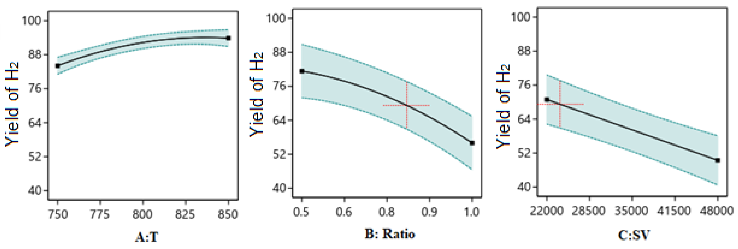
One Factor Effect (2D) Plot
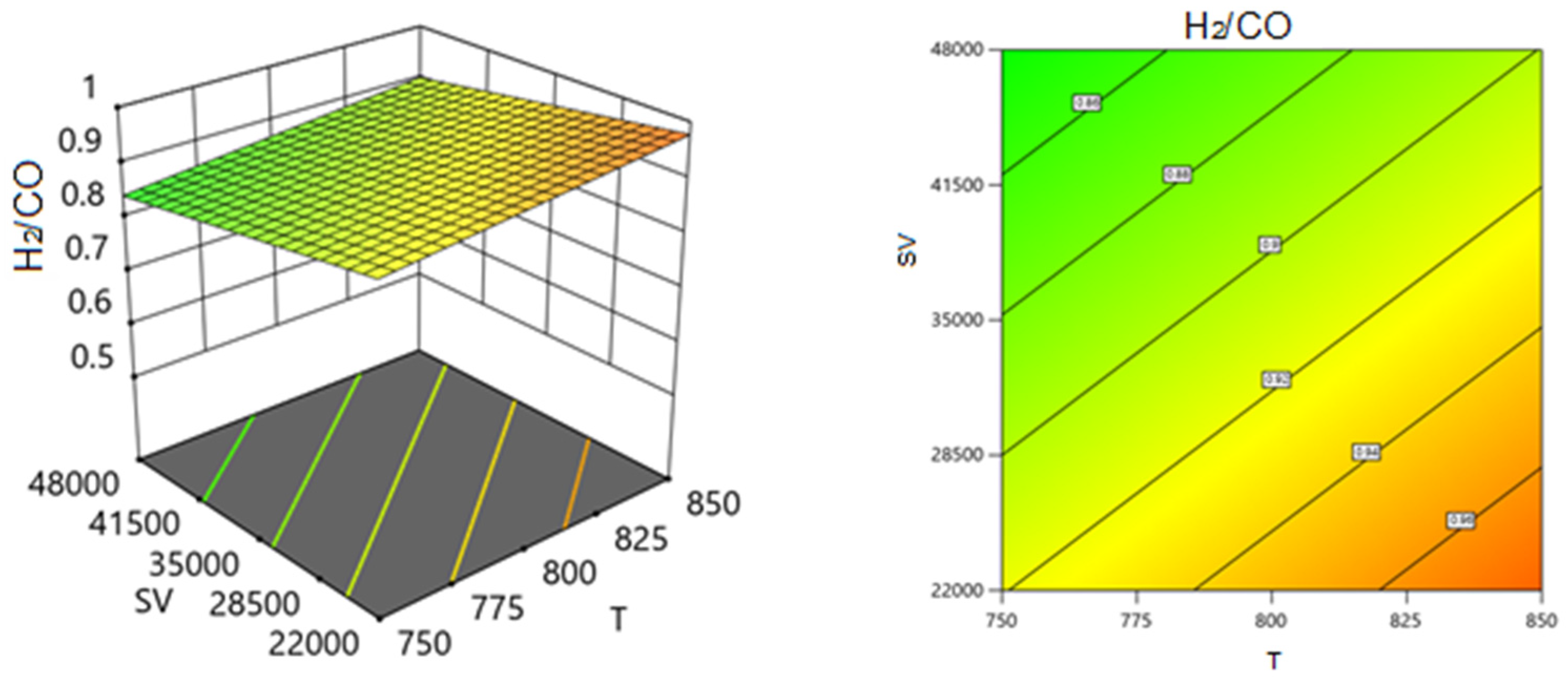
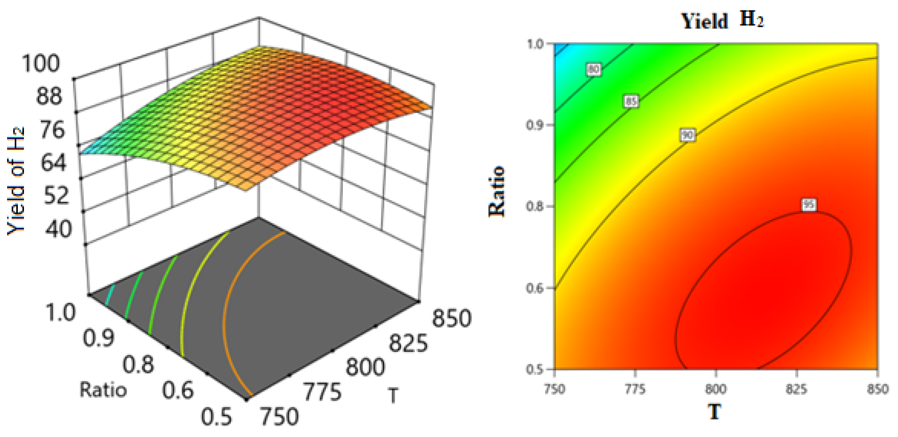
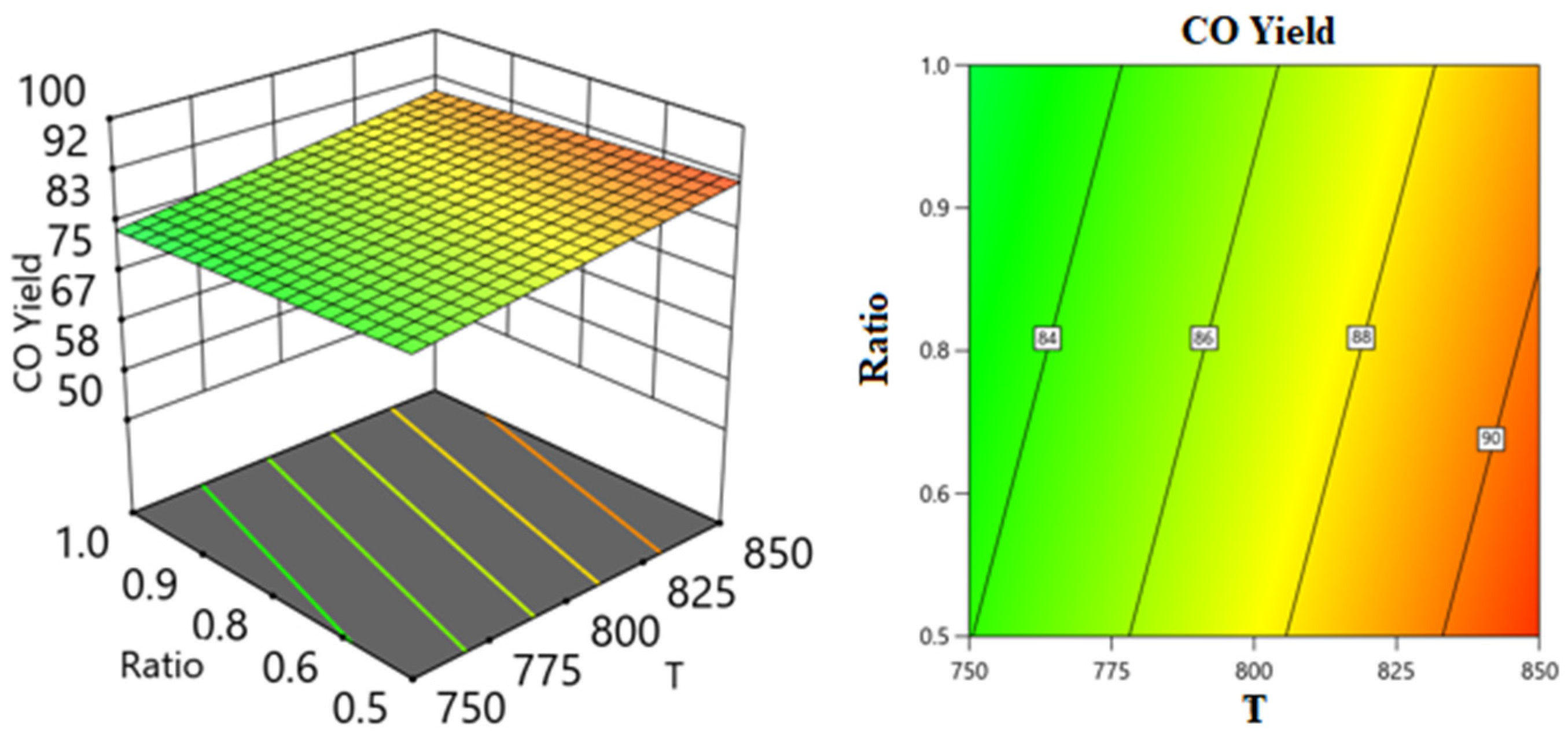
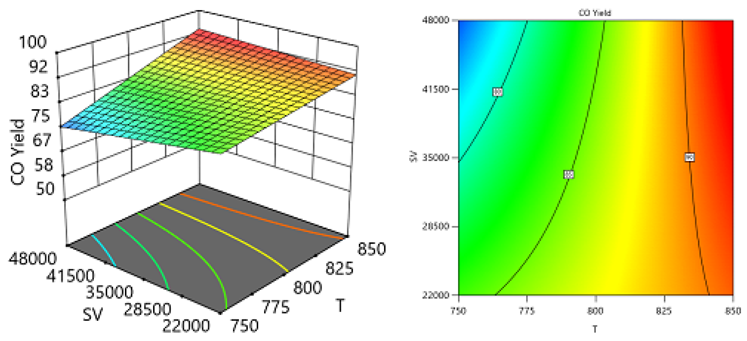
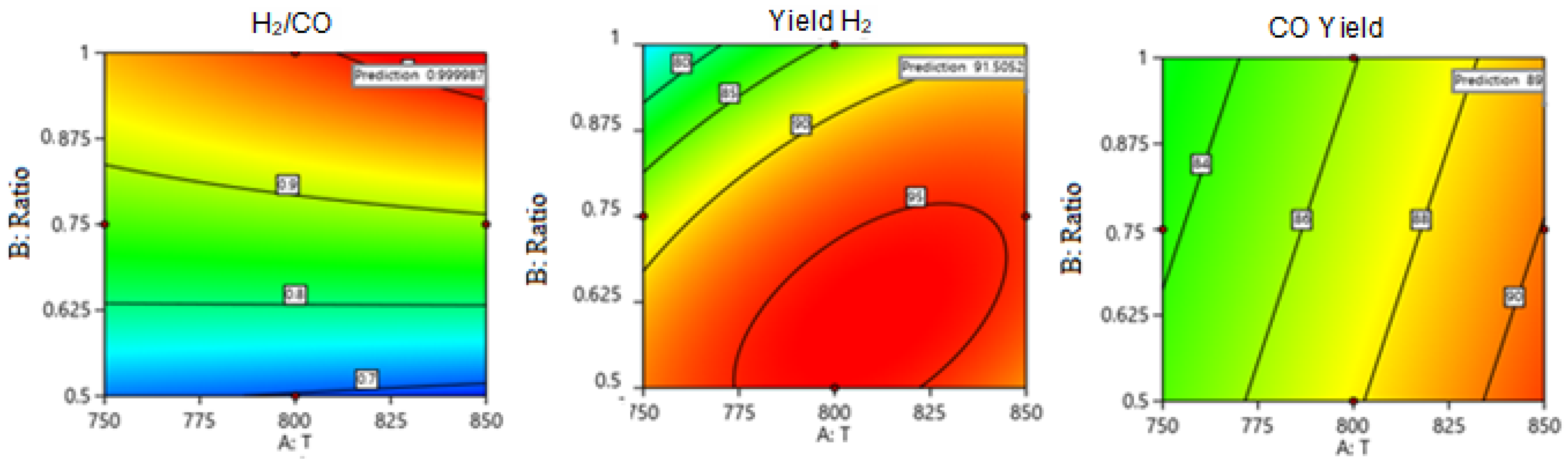
Two Factors Effect (3D Plot)
Optimization
4. Conclusions
Supplementary Materials
Author Contributions
Funding
Data Availability Statement
Acknowledgments
Conflicts of Interest
References
- Kumar, A.; Nagar, S.; Anand, S. Climate Change and Existential Threats. In Global Climate Change; Elsevier: Amsterdam, The Netherlands, 2021; pp. 1–31. [Google Scholar] [CrossRef]
- Abbass, K.; Qasim, M.Z.; Song, H.; Murshed, M.; Mahmood, H.; Younis, I. A Review of the Global Climate Change Impacts, Adaptation, and Sustainable Mitigation Measures. Environ. Sci. Pollut. Res. 2022, 29, 42539–42559. [Google Scholar] [CrossRef] [PubMed]
- Praveen, B.; Sharma, P. A Review of Literature on Climate Change and Its Impacts on Agriculture Productivity. J. Public Aff. 2019, 19, e1960. [Google Scholar] [CrossRef]
- Hussien, A.G.S.; Polychronopoulou, K. A Review on the Different Aspects and Challenges of the Dry Reforming of Methane (DRM) Reaction. Nanomaterials 2022, 12, 3400. [Google Scholar] [CrossRef] [PubMed]
- Al-Fatesh, A.S.; Patel, N.; Fakeeha, A.H.; Alotibi, M.F.; Alreshaidan, S.B.; Kumar, R. Reforming of Methane: Effects of Active Metals, Supports, and Promoters. Catal. Rev.-Sci. Eng. 2023, 65, 1–99. [Google Scholar] [CrossRef]
- Gallego, G.S.; Batiot-Dupeyrat, C.; Barrault, J.; Florez, E.; Mondragón, F. Dry Reforming of Methane over LaNi1-YByO3±δ (B = Mg, Co) Perovskites Used as Catalyst Precursor. Appl. Catal. A Gen. 2008, 334, 251–258. [Google Scholar] [CrossRef]
- Dou, J.; Zhang, R.; Hao, X.; Bao, Z.; Wu, T.; Wang, B.; Yu, F. Sandwiched SiO2@ Ni@ ZrO2 as a Coke Resistant Nanocatalyst for Dry Reforming of Methane. Appl. Catal. B Environ. 2019, 254, 612–623. [Google Scholar] [CrossRef]
- Grabchenko, M.V.; Dorofeeva, N.V.; Svetlichnyi, V.A.; Larichev, Y.V.; La Parola, V.; Liotta, L.F.; Kulinich, S.A.; Vodyankina, O. V Ni-Based SBA-15 Catalysts Modified with CeMnOx for CO2 Valorization via Dry Reforming of Methane: Effect of Composition on Modulating Activity and H2/CO Ratio. Nanomaterials 2023, 13, 2641. [Google Scholar] [CrossRef] [PubMed]
- Álvarez, M.A.; Bobadilla, L.F.; Garcilaso, V.; Centeno, M.A.; Odriozola, J.A. CO2 Reforming of Methane over Ni-Ru Supported Catalysts: On the Nature of Active Sites by Operando DRIFTS Study. J. CO2 Util. 2018, 24, 509–515. [Google Scholar] [CrossRef]
- Vang, R.T.; Honkala, K.; Dahl, S.; Vestergaard, E.K.; Schnadt, J.; Lægsgaard, E.; Clausen, B.S.; Nørskov, J.K.; Besenbacher, F. Controlling the Catalytic Bond-Breaking Selectivity of Ni Surfaces by Step Blocking. Nat. Mater. 2005, 4, 160–162. [Google Scholar] [CrossRef]
- Al-Fatesh, A.S.; Arafat, Y.; Kasim, S.O.; Ibrahim, A.A.; Abasaeed, A.E.; Fakeeha, A.H. In Situ Auto-Gasification of Coke Deposits over a Novel Ni-Ce/W-Zr Catalyst by Sequential Generation of Oxygen Vacancies for Remarkably Stable Syngas Production via CO2-Reforming of Methane. Appl. Catal. B Environ. 2021, 280, 119445. [Google Scholar] [CrossRef]
- Gao, N.; Cheng, M.; Quan, C.; Zheng, Y. Syngas Production via Combined Dry and Steam Reforming of Methane over Ni-Ce/ZSM-5 Catalyst. Fuel 2020, 273, 117702. [Google Scholar] [CrossRef]
- Zhu, Q.; Zhou, H.; Wang, L.; Wang, L.; Wang, C.; Wang, H.; Fang, W.; He, M.; Wu, Q.; Xiao, F.S. Enhanced CO2 Utilization in Dry Reforming of Methane Achieved through Nickel-Mediated Hydrogen Spillover in Zeolite Crystals. Nat. Catal. 2022, 5, 1030–1037. [Google Scholar] [CrossRef]
- Halliche, D.; Cherifi, O.; Auroux, A. Microcalorimetric Studies and Methane Reforming by CO2 on Ni-Based Zeolite Catalysts. Thermochim. Acta 2005, 434, 125–131. [Google Scholar] [CrossRef]
- Pawelec, B.; Damyanova, S.; Arishtirova, K.; Fierro, J.L.G.; Petrov, L. Structural and Surface Features of PtNi Catalysts for Reforming of Methane with CO2. Appl. Catal. A Gen. 2007, 323, 188–201. [Google Scholar] [CrossRef]
- Ray, D.; Nepak, D.; Janampelli, S.; Goshal, P.; Subrahmanyam, C. Dry Reforming of Methane in DBD Plasma over Ni-Based Catalysts: Influence of Process Conditions and Support on Performance and Durability. Energy Technol. 2019, 7, 1801008. [Google Scholar] [CrossRef]
- Moradi, G.; Khezeli, F.; Hemmati, H. Syngas Production with Dry Reforming of Methane over Ni/ZSM-5 Catalysts. J. Nat. Gas Sci. Eng. 2016, 33, 657–665. [Google Scholar] [CrossRef]
- Ballesteros-Plata, D.; Cecilia, J.A.; Barroso-Martín, I.; Jiménez-Jiménez, J.; Infantes-Molina, A.; Rodríguez-Castellón, E. Materials Design for N2O Capture: Separation in Gas Mixtures. Catalysts 2022, 12, 1539. [Google Scholar] [CrossRef]
- Joia, R.; Muhammad, H. Advancement of gas chromatography in quantitative analysis. Химия-биoлoгиялық сериясы 2023, 3, 18–31. [Google Scholar]
- Ayodele, B.V.; Abdullah, S. An Overview of Response Surface Methodology Approach to Optimization of Hydrogen and Syngas Production by Catalytic Reforming of Greenhouse Gases (CH4 and CO2). In Statistical Approaches with Emphasis on Design of Experiments Applied to Chemical Processes; Intechopen: London, UK, 2018; pp. 65–78. [Google Scholar]
- Jailani, M.S.A.M.; Miskan, S.N.; Bahari, M.B.; Setiabudi, H.D. Optimization of Dry Reforming of Methane over Yttrium Oxide-Cobalt/Mesoporous Alumina Using Response Surface Methodology. Mater. Today Proc. 2023, in press. [Google Scholar] [CrossRef]
- Hossain, M.A.; Ayodele, B.V.; Cheng, C.K.; Khan, M.R. Optimization of Renewable Hydrogen-Rich Syngas Production from Catalytic Reforming of Greenhouse Gases (CH4 and CO2) over Calcium Iron Oxide Supported Nickel Catalyst. J. Energy Inst. 2019, 92, 177–194. [Google Scholar] [CrossRef]
- Yusuf, M.; Farooqi, A.S.; Alam, M.A.; Keong, L.K.; Hellgardt, K.; Abdullah, B. Response Surface Optimization of Syngas Production from Greenhouse Gases via DRM over High Performance Ni–W Catalyst. Int. J. Hydrogen Energy 2022, 47, 31058–31071. [Google Scholar] [CrossRef]
- Hambali, H.U.; Jalil, A.A.; Abdulrasheed, A.A.; Siang, T.J.; Owgi, A.H.K.; Aziz, F.F.A. CO2 Reforming of Methane over Ta-Promoted Ni/ZSM-5 Fibre-like Catalyst: Insights on Deactivation Behavior and Optimization Using Response Surface Methodology (RSM). Chem. Eng. Sci. 2021, 231, 116320. [Google Scholar] [CrossRef]
- Chong, C.C.; Cheng, Y.W.; Setiabudi, H.D.; Ainirazali, N.; Vo, D.V.N.; Abdullah, B. Dry Reforming of Methane over Ni/Dendritic Fibrous SBA-15 (Ni/DFSBA-15): Optimization, Mechanism, and Regeneration Studies. Int. J. Hydrogen Energy 2020, 45, 8507–8525. [Google Scholar] [CrossRef]
- Shah, M.; Al Mesfer, M.K.; Danish, M. Design and Optimization of Ni–Fe–La Based Catalytic System for CO2 Utilization for Sustainable Syngas Production via Dry Reforming of Methane. J. Energy Inst. 2023, 110, 101346. [Google Scholar] [CrossRef]
- Treacy, M.M.J.; Higgins, J.B. Collection of Simulated XRD Powder Patterns for Zeolites, Fifth (5th) Revised Edition; Elsevier: Amsterdam, The Netherlands, 2007; ISBN 0080555780. [Google Scholar] [CrossRef]
- Joshi, M.S.; Mohan Prabhu, K. Synthesis and Characterization of ZSM-8-type Zeolite Crystals. Cryst. Res. Technol. 1988, 23, 561–566. [Google Scholar] [CrossRef]
- Macmillan, J.C. Chemical Physics. J. Frankl. Inst. 1877, 104, 298–299. [Google Scholar] [CrossRef]
- Kumar, R. Surface Characterization Techniques; De Gruyter: Berlin, Germany, 2022; ISBN 9783110656480. [Google Scholar] [CrossRef]
- Groen, J.C.; Peffer, L.A.A.; Pérez-Ramírez, J. Pore Size Determination in Modified Micro-and Mesoporous Materials. Pitfalls and Limitations in Gas Adsorption Data Analysis. Microporous Mesoporous Mater. 2003, 60, 1–17. [Google Scholar] [CrossRef]
- Kadlec, O.; Dubinin, M.M. Comments on the Limits of Applicability of the Mechanism of Capillary Condensation. J. Colloid Interface Sci. 1969, 31, 479–489. [Google Scholar] [CrossRef]
- Bremard, C.; Le Maire, M. Low-Frequency Raman Spectra of Dehydrated Faujasitic Zeolites. J. Phys. Chem. 1993, 97, 9695–9702. [Google Scholar] [CrossRef]
- Dutta, P.K.; Puri, M. Synthesis and Structure of Zeolite ZSM-5: A Raman Spectroscopic Study. J. Phys. Chem. 1987, 91, 4329–4333. [Google Scholar] [CrossRef]
- Zhai, K.; Xue, W.; Wang, H.; Wu, X.; Zhai, S. Raman Spectra of Sillimanite, Andalusite, and Kyanite at Various Temperatures. Phys. Chem. Miner. 2020, 47, 23. [Google Scholar] [CrossRef]
- McMillan, P.; Piriou, B. The Structures and Vibrational Spectra of Crystals and Glasses in the Silica-Alumina System. J. Non. Cryst. Solids 1982, 53, 279–298. [Google Scholar] [CrossRef]
- Ghule, A.V.; Ghule, K.; Punde, T.; Liu, J.Y.; Tzing, S.H.; Chang, J.Y.; Chang, H.; Ling, Y.C. In Situ Monitoring of NiO-Al2O3 Nanoparticles Synthesis by Thermo-Raman Spectroscopy. Mater. Chem. Phys. 2010, 119, 86–92. [Google Scholar] [CrossRef]
- Miecznikowski, A.; Hanuza, J. Infrared and Raman Studies of ZSM-5 and Silicalite-1 at Room, Liquid Nitrogen and Helium Temperatures. Zeolites 1987, 7, 249–254. [Google Scholar] [CrossRef]
- Dutta, P.K.; Rao, K.M.; Park, J.Y. Correlation of Raman Spectra of Zeolites with Framework Architecture. J. Phys. Chem. 1991, 95, 6654–6656. [Google Scholar] [CrossRef]
- Coudurier, G.; Naccache, C.; Vedrine, J.C. Uses of Ir Spectroscopy in Identifying ZSM Zeolite Structure. J. Chem. Soc. Chem. Commun. 1982, 1413–1415. [Google Scholar] [CrossRef]
- Ivanova, I.I.; Kuznetsov, A.S.; Yuschenko, V.V.; Knyazeva, E.E. Design of Composite Micro/Mesoporous Molecular Sieve Catalysts. Pure Appl. Chem. 2004, 76, 1647–1657. [Google Scholar] [CrossRef]
- Attallah, M.F.; Awwad, N.S.; Aly, H.F. Environmental Radioactivity of TE-NORM Waste Produced from Petroleum Industry in Egypt: Review on Characterization and Treatment. In Natural Gas-Extraction to End Use; IntechOpen: London, UK, 2012; pp. 75–158. [Google Scholar] [CrossRef]
- Al-Fatesh, A.S.; Kumar, R.; Kasim, S.O.; Ibrahim, A.A.; Fakeeha, A.H.; Abasaeed, A.E.; Alrasheed, R.; Bagabas, A.; Chaudhary, M.L.; Frusteri, F. The Effect of Modifier Identity on the Performance of Ni-Based Catalyst Supported on γ-Al2O3 in Dry Reforming of Methane. Catal. Today 2020, 348, 236–242. [Google Scholar] [CrossRef]
- Tang, M.; Xu, L.; Fan, M. Effect of Ce on 5 Wt% Ni/ZSM-5 Catalysts in the CO2 Reforming of CH4 Reaction. Int. J. Hydrogen Energy 2014, 39, 15482–15496. [Google Scholar] [CrossRef]
- Acharya, K.; Al-Fatesh, A.S.; Almutairi, G.; Fakeeha, A.H.; Ibrahim, A.A.; Abasaeed, A.E.; Siddiqui, M.R.H.; Kumar, R. The Role of Strontium as an Economic Promoter Over WO3 + ZrO2 Supported Ni Catalyst for H2 Production through Dry Reforming of Methane. Catal. Letters 2023, 154, 2023–2035. [Google Scholar] [CrossRef]
- Wierzbicki, D.; Baran, R.; Dębek, R.; Motak, M.; Gálvez, M.E.; Grzybek, T.; Da Costa, P.; Glatzel, P. Examination of the Influence of La Promotion on Ni State in Hydrotalcite-Derived Catalysts under CO2 Methanation Reaction Conditions: Operando X-ray Absorption and Emission Spectroscopy Investigation. Appl. Catal. B Environ. 2018, 232, 409–419. [Google Scholar] [CrossRef]
- Al-Fatesh, A.S.; Kumar, R.; Kasim, S.O.; Ibrahim, A.A.; Fakeeha, A.H.; Abasaeed, A.E.; Atia, H.; Armbruster, U.; Kreyenschulte, C.; Lund, H. Effect of Cerium Promoters on an MCM-41-Supported Nickel Catalyst in Dry Reforming of Methane. Ind. Eng. Chem. Res. 2021, 61, 164–174. [Google Scholar] [CrossRef]
- Pan, Q.; Peng, J.; Sun, T.; Wang, S.; Wang, S. Insight into the Reaction Route of CO2 Methanation: Promotion Effect of Medium Basic Sites. Catal. Commun. 2014, 45, 74–78. [Google Scholar] [CrossRef]
- Pizzolitto, C.; Pupulin, E.; Menegazzo, F.; Ghedini, E.; Di Michele, A.; Mattarelli, M.; Cruciani, G.; Signoretto, M. Nickel Based Catalysts for Methane Dry Reforming: Effect of Supports on Catalytic Activity and Stability. Int. J. Hydrogen Energy 2019, 44, 28065–28076. [Google Scholar] [CrossRef]
- Chaudhary, K.J.; Al-Fatesh, A.S.; Ibrahim, A.A.; Osman, A.I.; Fakeeha, A.H.; Alhoshan, M.; Alarifi, N.; Al-Muhtaseb, A.H.; Kumar, R. Enhanced Hydrogen Production through Methane Dry Reforming: Evaluating the Effects of Promoter-Induced Variations in Reducibility, Basicity, and Crystallinity on Ni/ZSM-5 Catalyst Performance. Energy Convers. Manag. X 2024, 23, 100631. [Google Scholar] [CrossRef]
- Kevan, L. Microporous Materials: Zeolites, Clays, and Aluminophosphates. In Encyclopedia of Physical Science and Technology; Academic Press: Cambridge, MA, USA, 2003. [Google Scholar]
- Zhang, L.; Liu, H.; Li, X.; Xie, S.; Wang, Y.; Xin, W.; Liu, S.; Xu, L. Differences between ZSM-5 and ZSM-11 Zeolite Catalysts in 1-Hexene Aromatization and Isomerization. Fuel Process. Technol. 2010, 91, 449–455. [Google Scholar] [CrossRef]
- Houalla, M.; Delannay, F.; Delmon, B. Joint Studies by X-ray Photoelectron Spectroscopy and Analytical Electron Microscopy of the Dispersion of Nickel Oxide Supported on Silica and Silica–Aluminas. J. Chem. Soc. Faraday Trans. 1 Phys. Chem. Condens. Phases 1980, 76, 1766–1772. [Google Scholar] [CrossRef]
- Damyanova, S.; Shtereva, I.; Pawelec, B.; Mihaylov, L.; Fierro, J.L.G. Characterization of None and Yttrium-Modified Ni-Based Catalysts for Dry Reforming of Methane. Appl. Catal. B Environ. 2020, 278, 119335. [Google Scholar] [CrossRef]
- Ibrahim, A.A.; Fakeeha, A.H.; Al-Fatesh, A.S. Enhancing Hydrogen Production by Dry Reforming Process with Strontium Promoter. Int. J. Hydrogen Energy 2014, 39, 1680–1687. [Google Scholar] [CrossRef]
- Pan, C.; Guo, Z.; Dai, H.; Ren, R.; Chu, W. Anti-Sintering Mesoporous Ni–Pd Bimetallic Catalysts for Hydrogen Production via Dry Reforming of Methane. Int. J. Hydrogen Energy 2020, 45, 16133–16143. [Google Scholar] [CrossRef]
- Mourhly, A.; Khachani, M.; Kacimi, M.; Halim, M.; Arsalane, S. A New Low-Cost Mesoporous Silica as a Promising Support of Ni-Catalysts for High-Hydrogen Generation via Dry Reforming of Methane. In Proceedings of the 2017 International Renewable and Sustainable Energy Conference (IRSEC), Tangier, Morocco, 4–7 December 2017; pp. 1–11. [Google Scholar] [CrossRef]
- Aguiar, M.; Cazula, B.B.; Saragiotto Colpini, L.M.; Borba, C.E.; Alves da Silva, F.; Noronha, F.B.; Alves, H.J. Si-MCM-41 Obtained from Different Sources of Silica and Its Application as Support for Nickel Catalysts Used in Dry Reforming of Methane. Int. J. Hydrogen Energy 2019, 44, 32003–32018. [Google Scholar] [CrossRef]
- Al-Fatesh, A.S.; Chaudhary, M.L.; Fakeeha, A.H.; Ibrahim, A.A.; Al-Mubaddel, F.; Kasim, S.O.; Albaqmaa, Y.A.; Bagabas, A.A.; Patel, R.; Kumar, R. Role of Mixed Oxides in Hydrogen Production through the Dry Reforming of Methane over Nickel Catalysts Supported on Modified γ-Al2O3. Processes 2021, 9, 157. [Google Scholar] [CrossRef]
- Hu, X.; Jia, X.; Zhang, X.; Liu, Y.; Liu, C. jun Improvement in the Activity of Ni/ZrO2 by Cold Plasma Decomposition for Dry Reforming of Methane. Catal. Commun. 2019, 128, 105720. [Google Scholar] [CrossRef]
- Khatri, J.; Al-Fatesh, A.S.; Fakeeha, A.H.; Ibrahim, A.A.; Abasaeed, A.E.; Kasim, S.O.; Osman, A.I.; Patel, R.; Kumar, R. Ce Promoted Lanthana-Zirconia Supported Ni Catalyst System: A Ternary Redox System for Hydrogen Production. Mol. Catal. 2021, 504, 111498. [Google Scholar] [CrossRef]
- Abasaeed, A.; Kasim, S.; Khan, W.; Sofiu, M.; Ibrahim, A.; Fakeeha, A.; Al-Fatesh, A. Hydrogen Yield from CO2 Reforming of Methane: Impact of La2O3 Doping on Supported Ni Catalysts. Energies 1997, 14, 2412. [Google Scholar] [CrossRef]
- Al-Fatesh, A.S.; Khatri, J.; Kumar, R.; Kumar Srivastava, V.; Osman, A.I.; AlGarni, T.S.; Ibrahim, A.A.; Abasaeed, A.E.; Fakeeha, A.H.; Rooney, D.W. Role of Ca, Cr, Ga and Gd Promotor over Lanthana-Zirconia–Supported Ni Catalyst towards H2-Rich Syngas Production through Dry Reforming of Methane. Energy Sci. Eng. 2022, 10, 866–880. [Google Scholar] [CrossRef]
- Chein, R.Y.; Fung, W.Y. Syngas Production via Dry Reforming of Methane over CeO2 Modified Ni/Al2O3 Catalysts. Int. J. Hydrogen Energy 2019, 44, 14303–14315. [Google Scholar] [CrossRef]
- Kumar, P.; Sun, Y.; Idem, R.O. Comparative Study of Ni-Based Mixed Oxide Catalyst for Carbon Dioxide Reforming of Methane. Energy Fuels 2008, 22, 3575–3582. [Google Scholar] [CrossRef]
- Patel, R.; Al-Fatesh, A.S.; Fakeeha, A.H.; Arafat, Y.; Kasim, S.O.; Ibrahim, A.A.; Al-Zahrani, S.A.; Abasaeed, A.E.; Srivastava, V.K.; Kumar, R. Impact of Ceria over WO3–ZrO2 Supported Ni Catalyst towards Hydrogen Production through Dry Reforming of Methane. Int. J. Hydrogen Energy 2021, 46, 25015–25028. [Google Scholar] [CrossRef]
- Kurdi, A.N.; Ibrahim, A.A.; Al-Fatesh, A.S.; Alquraini, A.A.; Abasaeed, A.E.; Fakeeha, A.H. Hydrogen Production from CO2 Reforming of Methane Using Zirconia Supported Nickel Catalyst. RSC Adv. 2022, 12, 10846–10854. [Google Scholar] [CrossRef]
- Patel, R.; Fakeeha, A.H.; Kasim, S.O.; Sofiu, M.L.; Ibrahim, A.A.; Abasaeed, A.E.; Kumar, R.; Al-Fatesh, A.S. Optimizing Yttria-Zirconia Proportions in Ni Supported Catalyst System for H2 Production through Dry Reforming of Methane. Mol. Catal. 2021, 510, 111676. [Google Scholar] [CrossRef]
- Chaudhary, M.L.; Al-Fatesh, A.S.; Kumar, R.; Lanre, M.S.; Frusteri, F.; AlReshaidan, S.B.; Ibrahim, A.A.; Abasaeed, A.E.; Fakeeha, A.H. Promotional Effect of Addition of Ceria over Yttria-Zirconia Supported Ni Based Catalyst System for Hydrogen Production through Dry Reforming of Methane. Int. J. Hydrogen Energy 2022, 47, 20838–20850. [Google Scholar] [CrossRef]
- Al-Fatesh, A.S.; Patel, R.; Srivastava, V.K.; Ibrahim, A.A.; Naeem, M.A.; Fakeeha, A.H.; Abasaeed, A.E.; Alquraini, A.A.; Kumar, R. Barium-Promoted Yttria–Zirconia-Supported Ni Catalyst for Hydrogen Production via the Dry Reforming of Methane: Role of Barium in the Phase Stabilization of Cubic ZrO2. ACS Omega 2022, 7, 16468–16483. [Google Scholar] [CrossRef] [PubMed]
- Fakeeha, A.H.; Patel, R.; El Hassan, N.; Al-Zahrani, S.A.; Al-Awadi, A.S.; Frusteri, L.; Bayahia, H.; Alharth, A.I.; Al-Fatesh, A.S.; Kumar, R. Holmium Promoted Yttria-Zirconia Supported Ni Catalyst for H2 Production via Dry Reforming of Methane. Int. J. Hydrogen Energy 2022, 47, 38242–38257. [Google Scholar] [CrossRef]
- Abasaeed, A.E.; Sofiu, M.L.; Acharya, K.; Osman, A.I.; Fakeeha, A.H.; AL-Otaibi, R.L.; Ibrahim, A.A.; Al-Awadi, A.S.; Bayahia, H.; Al-Zahrani, S.A. The Influence of Ni Stability, Redox, and Lattice Oxygen Capacity on Catalytic Hydrogen Production via Methane Dry Reforming in Innovative Metal Oxide Systems. Energy Sci. Eng. 2023, 11, 1436–1450. [Google Scholar] [CrossRef]
- Miskan, S.N.; Setiabudi, H.D.; Bahari, M.B.; Vo, D.-V.N.; Abdullah, B.; Jalil, A.A.; Muhammad, S.A.F.S.; Ismail, S.B. Properties-Activity Correlation of Nickel Supported on Fibrous Zeolite-Y for Dry Reforming of Methane. Int. J. Hydrogen Energy 2024, 52, 268–277. [Google Scholar] [CrossRef]


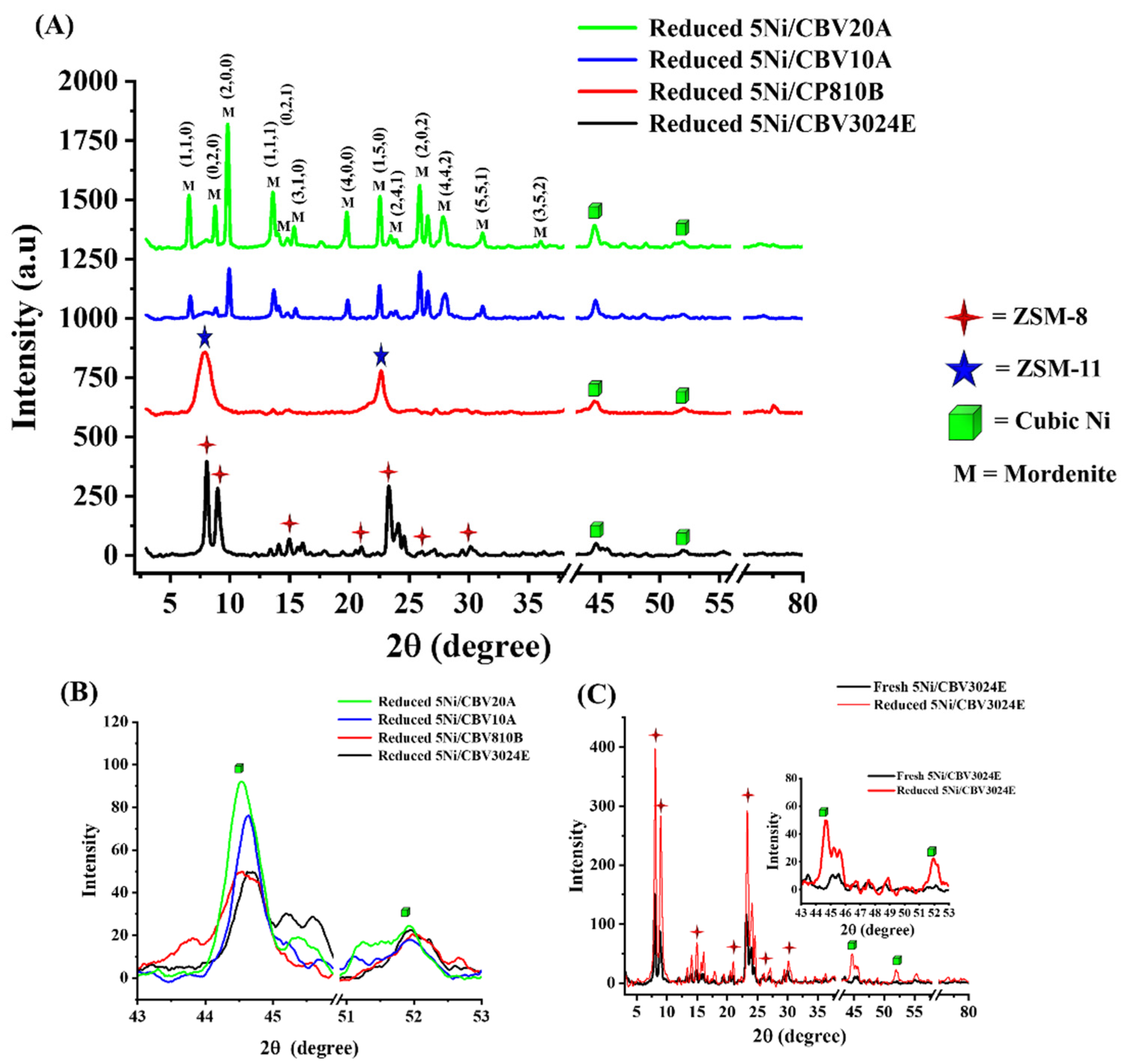
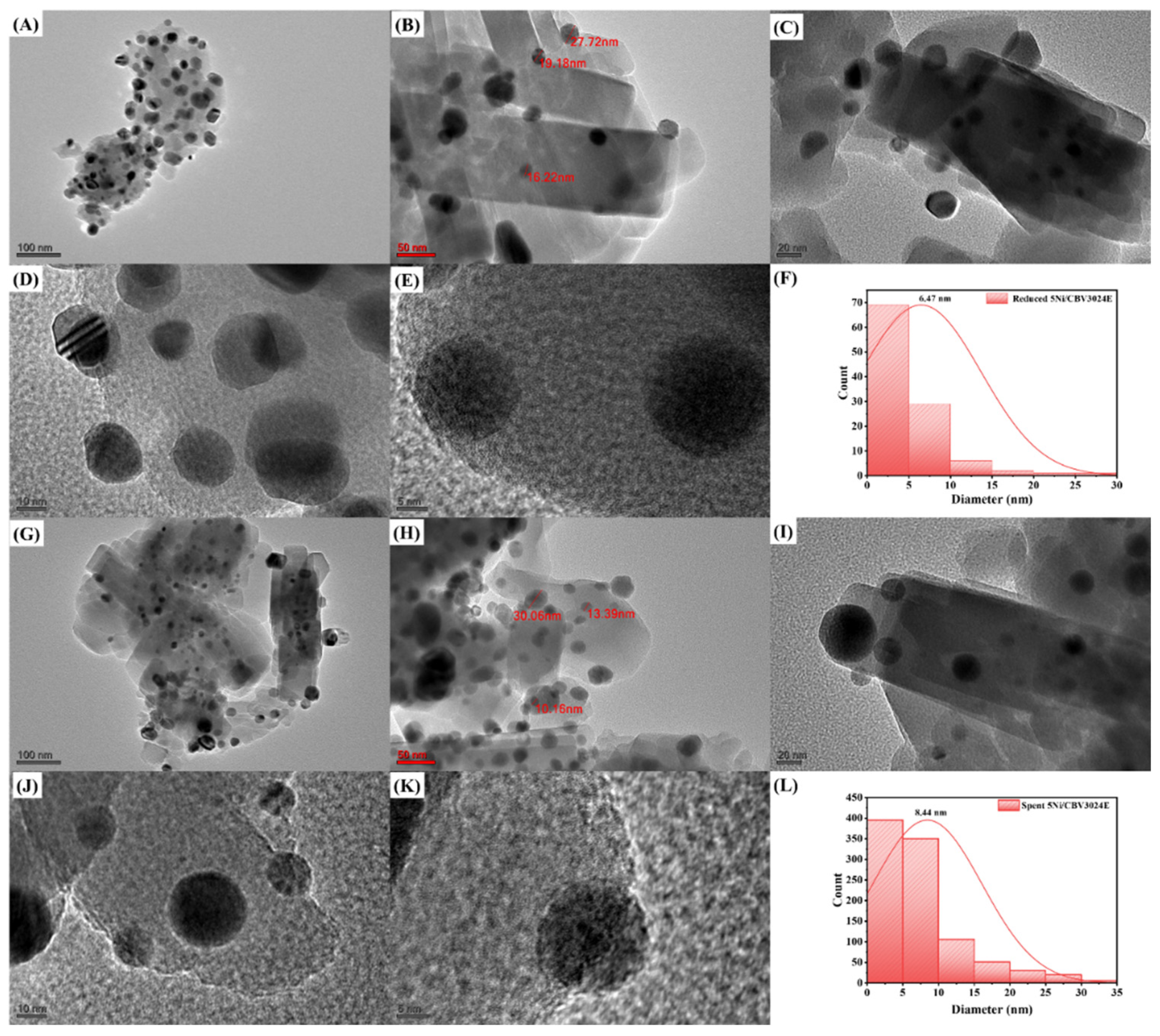
| Catalyst Name | The Crystallite Size of Ni (nm) |
|---|---|
| 5Ni/CBV 3024E | 13.9 |
| 5Ni/CBV810B | 13.9 |
| 5Ni/CBV10A | 15.9 |
| 5Ni/CBV20A | 22.2 |
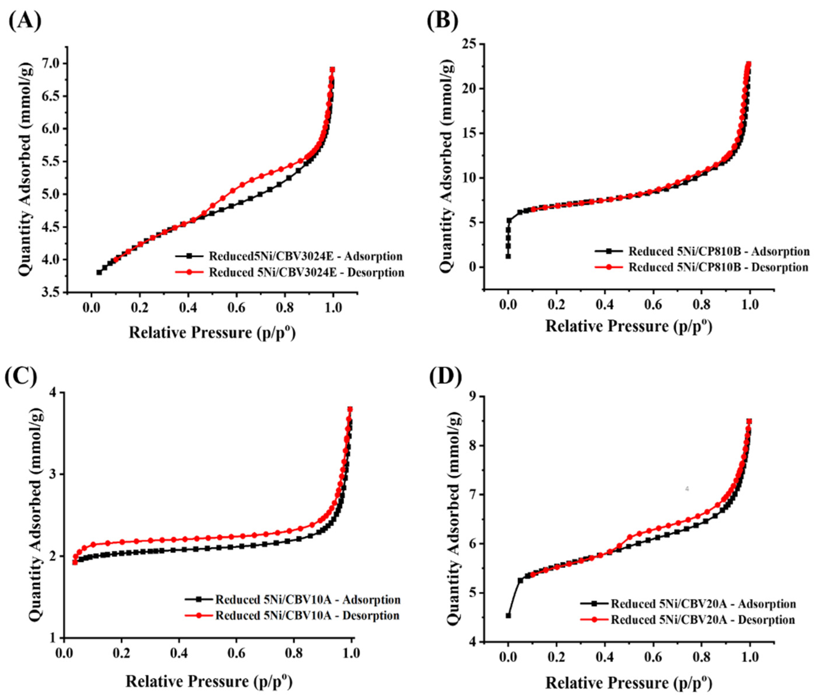
| Reduced Catalyst | Surface Area (m2/g) | Pore Volume (cm3/g) | Average Pore Diameter (nm) |
|---|---|---|---|
| CBV 3024E | 405 | 0.12 | 7.52 |
| 5Ni/CBV 3024E | 304 | 0.13 | 5.55 |
| CP810B | 682 | 0.61 | 14.18 |
| 5Ni/CP810B | 496 | 0.62 | 13.7 |
| CBV 10A | 425 | 0.07 | 16.58 |
| 5Ni/CBV 10A | 142 | 0.06 | 15.70 |
| CBV 20A | 500 | 0.13 | 7.82 |
| 5Ni/CBV 20A | 390 | 0.13 | 7.24 |
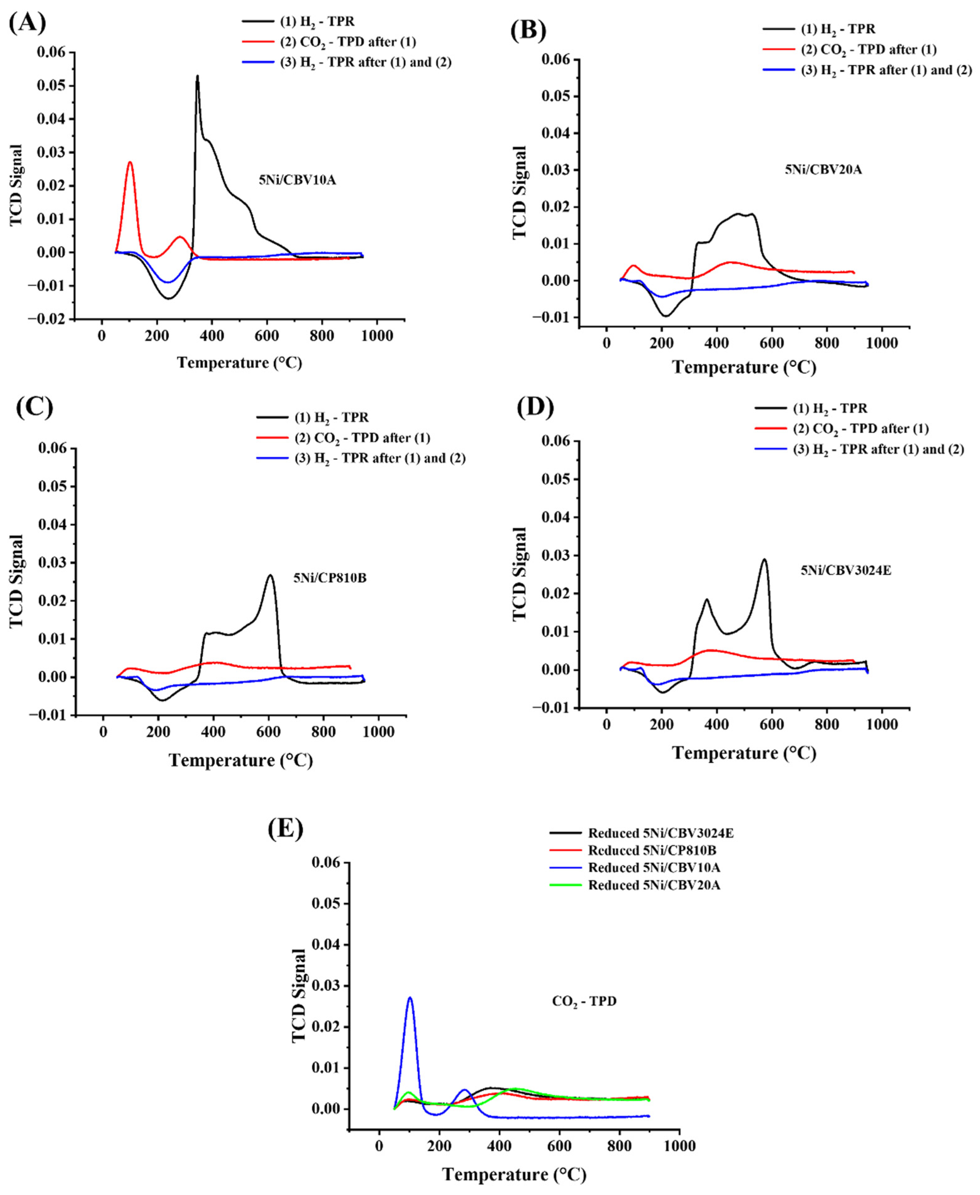
| Catalyst Name | Temp. (°C) (Peak 1) 300–400 °C | H2 Consumption Amount (cm3/g) | Temp. (°C) (Peak 2) 500–600 °C | H2 Consumption Amount (cm3/g) | Total Amount (cm3/g) | |
|---|---|---|---|---|---|---|
| First H2-TPR | 5Ni/CBV3024E | 363 | 4.799 | 572 | 7.992 | 12.791 |
| 5Ni/CP810B | 405 | 4.261 | 606 | 11.429 | 15.69 | |
| 5Ni/CBV10A | 347 | 20.498 | - | - | 20.498 | |
| 5Ni/CBV20A | 477 | 9.726 | 525 | 5.245 | 14.971 | |
| Catalyst Name | Temp. (°C) (Peak 1) ~100 °C | CO2 Desorption Amount (cm3/g) | Temp. (°C) (Peak 2) ~300–400 °C | CO2 Desorption Amount (cm3/g) | Total | |
| CO2-TPD of reduced catalyst | Reduced-5Ni/CBV3024E | 85 | 0.126 | 371 | 0.778 | 0.904 |
| Reduced-5Ni/CP810B | 96 | 0.198 | 383 | 0.548 | 0.746 | |
| Reduced-5Ni/CBV10A | 103 | 2.191 | 283 | 0.708 | 2.899 | |
| Reduced-5Ni/CBV20A | 97 | 0.487 | 443 | 0.933 | 1.42 |
| Levels | ||
|---|---|---|
| Process Parameter | −1 (low) | +1 (high) |
| Gas hour space velocity (ccg−1h−1) | 22,000 | 48,000 |
| Temperature (°C) | 750 | 850 |
| Ratio | 0.5 | 1 |
| Source | Sum of Squares | df | Mean Square | F-Value | p-Value |
|---|---|---|---|---|---|
| Response 1: H2/CO ratio (R2 = 0.9923) | |||||
| Model | 0.1514 | 6 | 0.0252 | 172.89 | <0.0001 |
| A: Temperature | 0.0002 | 1 | 0.0002 | 1.64 | 0.2367 |
| B: Ratio | 0.0099 | 1 | 0.0099 | 67.5 | <0.0001 |
| C: SV | 0.0008 | 1 | 0.0008 | 5.23 | 0.0515 |
| AB | 0.003 | 1 | 0.003 | 20.72 | 0.0019 |
| BC | 0.0012 | 1 | 0.0012 | 8.39 | 0.02 |
| 0.0039 | 1 | 0.0039 | 26.42 | 0.0009 | |
| B2 | 0.1514 | 6 | 0.0252 | 172.89 | <0.0001 |
| Response 2: H2 yield (R2 = 0.9795) | |||||
| Model | 905.55 | 7 | 129.36 | 47.71 | <0.0001 |
| A: Temperature | 29.34 | 1 | 29.34 | 10.82 | 0.0133 |
| B: Ratio | 24.95 | 1 | 24.95 | 9.2 | 0.019 |
| C: SV | 102.39 | 1 | 102.39 | 37.76 | 0.0005 |
| AB | 56.63 | 1 | 56.63 | 20.88 | 0.0026 |
| AC | 44.29 | 1 | 44.29 | 16.33 | 0.0049 |
| A2 | 41.19 | 1 | 41.19 | 15.19 | 0.0059 |
| B2 | 51.54 | 1 | 51.54 | 19.01 | 0.0033 |
| Response 3: CO yield (R2 = 0.8846) | |||||
| Model | 348.01 | 4 | 87 | 19.16 | 0.0001 |
| A: Temperature | 5.45 | 1 | 5.45 | 1.2 | 0.2989 |
| B: Ratio | 7.26 | 1 | 7.26 | 1.6 | 0.2347 |
| C: SV | 45.25 | 1 | 45.25 | 9.97 | 0.0102 |
| AC | 32.09 | 1 | 32.09 | 7.07 | 0.0239 |
| Exp No | Variables | Response | ||||||||||
|---|---|---|---|---|---|---|---|---|---|---|---|---|
| A: Temperature | B: CH4/CO Ratio | C: SV | H2/CO | H2 Yield | CO Yield | |||||||
| Exp. | Pred. | Exp. | Pred. | Exp. | Pred. | |||||||
| 1 | 800 | 0.75 | 35000 | 0.85 | 0.8471 | 0.34 | 91.01 | 90.26 | 0.82 | 87.84 | 85.4 | 2.78 |
| 2 | 800 | 0.75 | 35000 | 0.85 | 0.8471 | 0.34 | 91.01 | 90.26 | 0.82 | 87.84 | 85.4 | 2.78 |
| 3 | 800 | 1 | 48000 | 0.91 | 0.8988 | 1.23 | 77.29 | 77.3 | 0.01 | 83.2 | 82.97 | 0.27 |
| 4 | 750 | 1 | 35000 | 0.89 | 0.9038 | 1.55 | 69.31 | 67.46 | 2.67 | 76.71 | 78.41 | 2.22 |
| 5 | 850 | 1 | 35000 | 0.97 | 0.9863 | 1.68 | 89.55 | 88.62 | 1.04 | 91.13 | 90.48 | 0.71 |
| 6 | 800 | 0.75 | 35000 | 0.85 | 0.8471 | 0.34 | 91.01 | 90.26 | 0.82 | 88.04 | 85.4 | 3.00 |
| 7 | 800 | 1 | 22000 | 1.01 | 0.9913 | 1.85 | 82.68 | 85.45 | 3.35 | 83.09 | 85.91 | 3.39 |
| 8 | 750 | 0.75 | 48000 | 0.8 | 0.8046 | 0.58 | 70.9 | 72.71 | 2.55 | 74.09 | 75.06 | 1.31 |
| 9 | 800 | 0.5 | 48000 | 0.67 | 0.6738 | 0.57 | 88.07 | 87.62 | 0.51 | 85.05 | 84.88 | 0.20 |
| 10 | 750 | 0.75 | 22000 | 0.86 | 0.8621 | 0.24 | 87.28 | 87.52 | 0.27 | 84.19 | 83.66 | 0.62 |
| 11 | 800 | 0.5 | 22000 | 0.7 | 0.6963 | 0.53 | 95.85 | 95.78 | 0.08 | 88.05 | 87.82 | 0.26 |
| 12 | 750 | 0.5 | 35000 | 0.7 | 0.6987 | 0.17 | 85.51 | 85.31 | 0.23 | 79.79 | 80.31 | 0.66 |
| 13 | 850 | 0.75 | 48000 | 0.84 | 0.8321 | 0.94 | 92.11 | 93 | 0.96 | 92.15 | 92.79 | 0.70 |
| 14 | 850 | 0.75 | 22000 | 0.88 | 0.8896 | 1.09 | 95.18 | 94.5 | 0.72 | 90.92 | 90.07 | 0.94 |
| 15 | 850 | 0.5 | 35000 | 0.67 | 0.6713 | 0.19 | 90.7 | 91.42 | 0.80 | 88.86 | 92.38 | 3.96 |
| MAPE | 0.78 | 1.04 | 1.59 | |||||||||
| Objective Function: Max (H2/CO and Max (H2 yield) and Max (CO yield) | Variables | ||||||
| T | SV | H2/CO | H2 Yield % | CO Yield% | |||
| Criteria | value | value | value | Max. | Max. | Max. | |
| Theoretical | 850 | 0.932 | 22,000.009 | 1 | 91.505 | 89.376 | |
| Experimental | 850 | 0.932 | 22,000 | 1 | 91.92 | 89.16 | |
| Catalyst | Catalyst Wt (g) | GHSV (L/h.gcat) | RT (°C) | TOS (h) | (%) | Ref. |
|---|---|---|---|---|---|---|
| 10Ni1Y/Al | 0.05 | 120 | 550 | 5 | 35 | [54] |
| 10Ni1RhY/Al | 0.05 | 120 | 650 | 5 | 45 | [54] |
| Ni0.75Sr/Al2O3 | 0.6 | 3.6 | 700 | 6 | 72 | [55] |
| 5Ni-SP-OA | 0.1 | 24 | 700 | 6 | 45 | [56] |
| 7.5Ni-SiO2-Imp | 0.1 | 24 | 700 | 6 | 32 | [56] |
| NiPd-SiO2-Imp | 0.1 | 24 | 700 | 6 | 88 | [56] |
| Ni-20/MSN | 0.02 | 180 | 700 | 3 | 71 | [57] |
| 20Ni/Si-MCM-41_RHA | 0.02 | 30 | 700 | 4 | 38 | [58] |
| 20Ni/Si-MCM-41_RHA | 0.02 | 30 | 800 | 24 | 50 | [58] |
| 5Ni/ZSM-5 | 0.15 | 28 | 700 | 18 | 27 | [50] |
| 5Ni2Ce/ZSM5 | 0.15 | 28 | 800 | 5 | 68 | [50] |
| 5Ni3Si/Al | 0.1 | 42 | 700 | ~7 | 62 | [59] |
| 5Ni3W/Al | 0.1 | 42 | 700 | ~7 | 62 | [59] |
| 5Ni3TiAl2O3 | 0.1 | 42 | 700 | 7 | 30 | [59] |
| 5Ni3MoAl2O3 | 0.1 | 42 | 700 | 7 | 39 | [59] |
| 10Ni/ZrO2 | 0.05 | 48 | 700 | 0.5 | 45 | [60] |
| 5Ni/ZrO2 | 0.1 | 42 | 700 | 7 | 43 | [61] |
| 5Ni1Ce/ZrO2 | 0.1 | 42 | 700 | ~7 | 47 | [61] |
| 5Ni/15La85Zr | 0.1 | 42 | 700 | 7 | 84 | [62] |
| 5Ni/9La91Zr | 0.1 | 42 | 700 | ~7 | 80 | [61] |
| 5Ni2.5Ce/9La91Zr | 0.1 | 42 | 700 | ~7 | 87 | [61] |
| 5Ni/9La91Zr | 0.1 | 42 | 700 | ~7 | 58 | [63] |
| 5Ni1Gd/9La91Zr | 0.1 | 42 | 700 | ~7 | 80 | [63] |
| 5Ni1Cr/9La91Zr | 0.1 | 42 | 700 | ~7 | 81 | [63] |
| 10Ni/CeO2 | 0.15 | 40 | 750 | 12 | 12 | [64] |
| 5Ni/CeO2-ZrO2 (Ce/Zr = 60/40) | 0.15 | 40 | 700 | 7 | 57 | [65] |
| 5Ni/9W91Zr | 0.1 | 42 | 700 | ~7 | 43 | [66] |
| 5Ni2.5Ce/9W91Zr | 0.1 | 42 | 700 | 7 | 78 | [66] |
| 5Ni15YZrO2 | 0.1 | 42 | 700 | 7 | 55 | [67] |
| 5Ni/15Y85Zr | 0.1 | 42 | 700 | 7 | 64 | [68] |
| 5Ni/13Y77Zr | 0.1 | 42 | 700 | ~7 | 67 | [69] |
| 5Ni2Ce/13Y77Zr | 0.1 | 42 | 700 | ~7 | 80 | [69] |
| 5Ni4Ba/13Y77Zr | 0.1 | 42 | 800 | ~7 | 80 | [70] |
| 5Ni4Ho/13Y77Zr | 0.1 | 42 | 700 | ~7 | 84 | [71] |
| La0.6Ce0.4Ni0.9Zr0.1O3 | 0.1 | 42 | 800 | 7 | 83 | [72] |
| CeNi0.9Zr0.01Y0.09O3 | 0.1 | 42 | 800 | 7 | 85 | [72] |
| 5Ni/FHY | 0.1 | 15 | 800 | 30 | 75 | [73] |
| 5Ni/CBV3024E | 0.1 | 42 | 700 | 5 | 44 | This work |
| 5Ni/CBV3024E | 0.1 | 22 | 850 | 5 | 92 | This work |
Disclaimer/Publisher’s Note: The statements, opinions and data contained in all publications are solely those of the individual author(s) and contributor(s) and not of MDPI and/or the editor(s). MDPI and/or the editor(s) disclaim responsibility for any injury to people or property resulting from any ideas, methods, instructions or products referred to in the content. |
© 2024 by the authors. Licensee MDPI, Basel, Switzerland. This article is an open access article distributed under the terms and conditions of the Creative Commons Attribution (CC BY) license (https://creativecommons.org/licenses/by/4.0/).
Share and Cite
Al-Fatesh, A.S.; Ibrahim, A.A.; Fakeeha, A.H.; Osman, A.I.; Alanazi, Y.M.; Almubaddel, F.S.; Abasaeed, A.E. Ni-Based Molecular Sieves Nanomaterials for Dry Methane Reforming: Role of Porous Structure and Active Sites Distribution on Hydrogen Production. Nanomaterials 2024, 14, 1320. https://doi.org/10.3390/nano14151320
Al-Fatesh AS, Ibrahim AA, Fakeeha AH, Osman AI, Alanazi YM, Almubaddel FS, Abasaeed AE. Ni-Based Molecular Sieves Nanomaterials for Dry Methane Reforming: Role of Porous Structure and Active Sites Distribution on Hydrogen Production. Nanomaterials. 2024; 14(15):1320. https://doi.org/10.3390/nano14151320
Chicago/Turabian StyleAl-Fatesh, Ahmed S., Ahmed A. Ibrahim, Anis H. Fakeeha, Ahmed I. Osman, Yousef M. Alanazi, Fahad Saleh Almubaddel, and Ahmed E. Abasaeed. 2024. "Ni-Based Molecular Sieves Nanomaterials for Dry Methane Reforming: Role of Porous Structure and Active Sites Distribution on Hydrogen Production" Nanomaterials 14, no. 15: 1320. https://doi.org/10.3390/nano14151320
APA StyleAl-Fatesh, A. S., Ibrahim, A. A., Fakeeha, A. H., Osman, A. I., Alanazi, Y. M., Almubaddel, F. S., & Abasaeed, A. E. (2024). Ni-Based Molecular Sieves Nanomaterials for Dry Methane Reforming: Role of Porous Structure and Active Sites Distribution on Hydrogen Production. Nanomaterials, 14(15), 1320. https://doi.org/10.3390/nano14151320