
ZIF-8-Based Nitrogen and Monoatomic Metal Co-Doped Pyrolytic Porous Carbon for High-Performance Supercapacitor Applications


Abstract
:1. Introduction
2. Materials and Methods
2.1. Materials and Reagents
2.2. Preparation of ZIF-8-Based Nitrogen-Doped Porous Carbon
2.3. Characterizations of Materials
2.4. Electrochemical Measurements
3. Results and Discussion
3.1. Material Characteristics
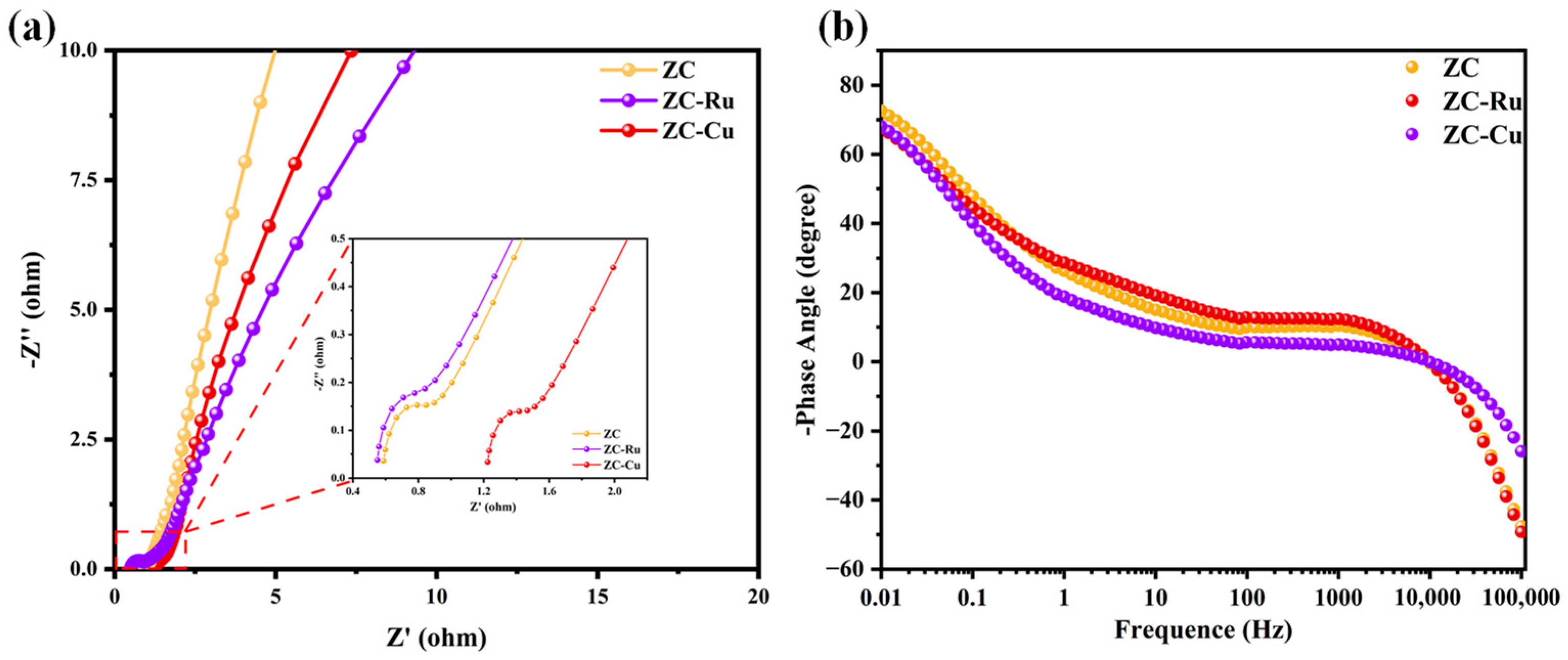
3.2. Electrochemical Properties in a Three-Electrode System
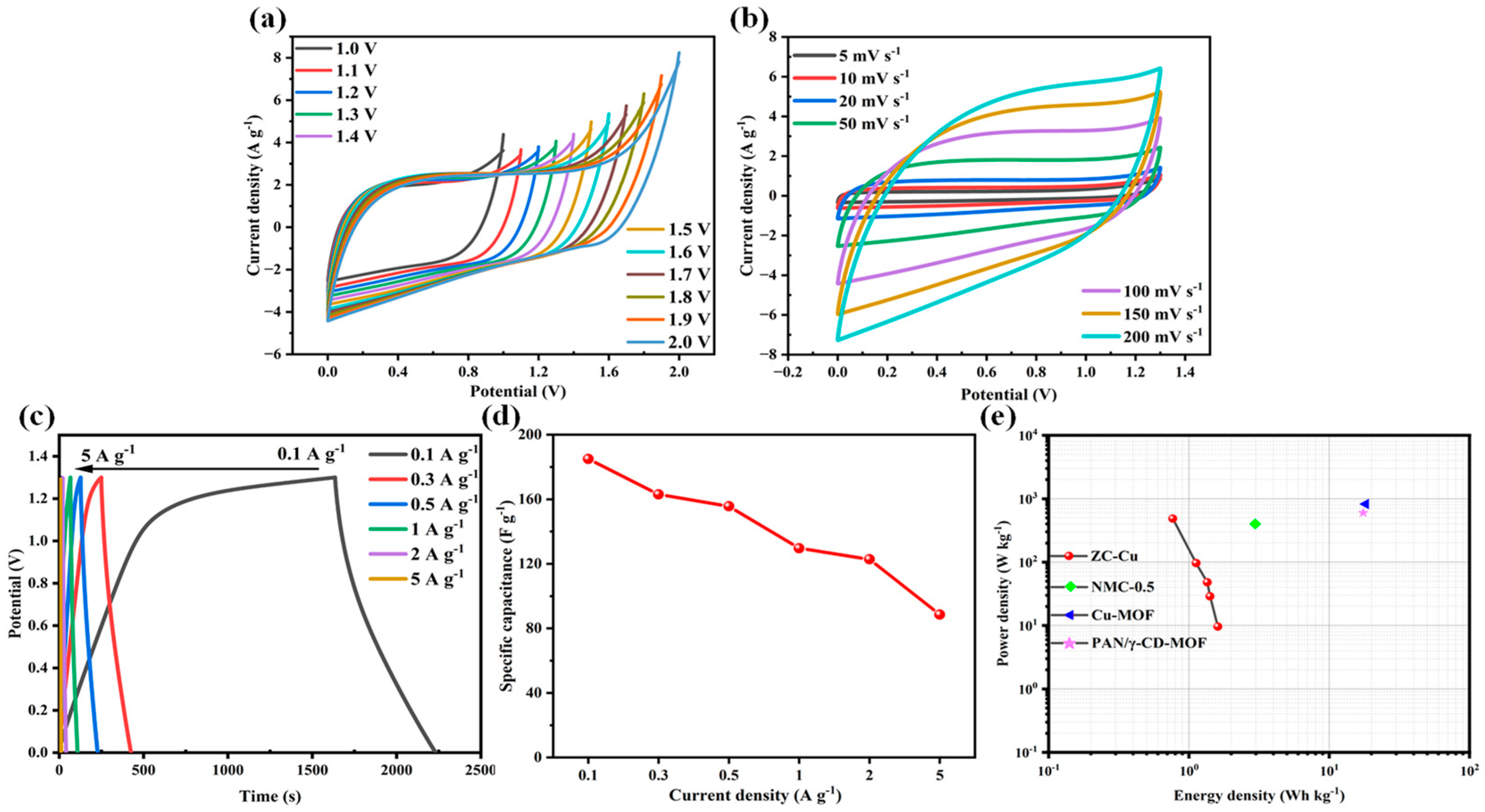
3.3. Electrochemical Properties in a Symmetric Electrode System
4. Conclusions
Supplementary Materials
Author Contributions
Funding
Data Availability Statement
Acknowledgments
Conflicts of Interest
References
- Foster, V.; Trotter, P.A.; Werner, S.; Niedermayer, M.; Mulugetta, Y.; Achakulwisut, P.; Brophy, A.; Dubash, N.K.; Fankhauser, S.; Hawkes, A.; et al. Development transitions for fossil fuel-producing low and lower-middle income countries in a carbon-constrained world. Nat. Energy 2024, 9, 242–250. [Google Scholar] [CrossRef]
- Paritosh, K.; Bose, A. Application of biogenic carbon in renewable energy vectors and devices: A step forward to decarbonization. Renew. Sustain. Energy Rev. 2024, 197, 16. [Google Scholar] [CrossRef]
- Somoye, O.A. Energy crisis and renewable energy potentials in Nigeria: A review. Renew. Sustain. Energy Rev. 2023, 188, 113794. [Google Scholar] [CrossRef]
- Ohba, M.; Kanno, Y.; Bando, S. Effects of meteorological and climatological factors on extremely high residual load and possible future changes. Renew. Sustain. Energy Rev. 2023, 175, 113188. [Google Scholar] [CrossRef]
- Al Shaqsi, A.Z.; Sopian, K.; Al-Hinai, A. Review of energy storage services, applications, limitations, and benefits. Energy Rep. 2020, 6, 288–306. [Google Scholar] [CrossRef]
- Lamba, P.; Singh, P.; Singh, P.; Singh, P.; Bharti; Kumar, A.; Gupta, M.; Kumar, Y. Recent advancements in supercapacitors based on different electrode materials: Classifications, synthesis methods and comparative performance. J. Energy Storage 2022, 48, 103871. [Google Scholar] [CrossRef]
- Guo, L.; Hu, P.; Wei, H. Development of supercapacitor hybrid electric vehicle. J. Energy Storage 2023, 65, 107269. [Google Scholar] [CrossRef]
- Wang, D.-G.; Liang, Z.; Gao, S.; Qu, C.; Zou, R. Metal-organic framework-based materials for hybrid supercapacitor application. Coord. Chem. Rev. 2020, 404, 213093. [Google Scholar] [CrossRef]
- Shinde, P.A.; Abbas, Q.; Chodankar, N.R.; Ariga, K.; Abdelkareem, M.A.; Olabi, A.G. Strengths, weaknesses, opportunities, and threats (SWOT) analysis of supercapacitors: A review. J. Energy Chem. 2023, 79, 611–638. [Google Scholar] [CrossRef]
- Ajdari, F.B.; Kowsari, E.; Shahrak, M.N.; Ehsani, A.; Kiaei, Z.; Torkzaban, H.; Ershadi, M.; Eshkalak, S.K.; Haddadi-Asl, V.; Chinnappan, A.; et al. A review on the field patents and recent developments over the application of metal organic frameworks (MOFs) in supercapacitors. Coord. Chem. Rev. 2020, 422, 213441. [Google Scholar] [CrossRef]
- Iro, Z.S.; Subramani, C.; Dash, S.S. A Brief Review on Electrode Materials for Supercapacitor. Int. J. Electrochem. Sci. 2016, 11, 10628–10643. [Google Scholar] [CrossRef]
- Poonam; Sharma, K.; Arora, A.; Tripathi, S.K. Review of supercapacitors: Materials and devices. J. Energy Storage 2019, 21, 801–825. [Google Scholar] [CrossRef]
- Zhong, M.; Zhang, M.; Li, X. Carbon nanomaterials and their composites for supercapacitors. Carbon Energy 2022, 4, 950–985. [Google Scholar] [CrossRef]
- Iqbal, M.Z.; Aziz, U. Supercapattery: Merging of battery-supercapacitor electrodes for hybrid energy storage devices. J. Energy Storage 2022, 46, 103823. [Google Scholar] [CrossRef]
- Loganathan, N.N.; Perumal, V.; Pandian, B.R.; Atchudan, R.; Edison, T.N.J.I.; Ovinis, M. Recent studies on polymeric materials for supercapacitor development. J. Energy Storage 2022, 49, 104149. [Google Scholar] [CrossRef]
- Majumdar, D.; Maiyalagan, T.; Jiang, Z. Recent Progress in Ruthenium Oxide-Based Composites for Supercapacitor Applications. Chemelectrochem 2019, 6, 4343–4372. [Google Scholar] [CrossRef]
- Saini, S.; Chand, P.; Joshi, A. Biomass derived carbon for supercapacitor applications: Review. J. Energy Storage 2021, 39, 102646. [Google Scholar] [CrossRef]
- Rawat, S.; Mishra, R.K.; Bhaskar, T. Biomass derived functional carbon materials for supercapacitor applications. Chemosphere 2022, 286, 131961. [Google Scholar] [CrossRef] [PubMed]
- Anil Kumar, Y.; Kim, H.-J. Preparation and electrochemical performance of NiCo2O4@NiCo2O4 composite nanoplates for high performance supercapacitor applications. New J. Chem. 2018, 42, 19971–19978. [Google Scholar] [CrossRef]
- Yan, L.; Liu, A.; Ma, R.; Guo, C.; Ding, X.; Feng, P.; Jia, D.; Xu, M.; Ai, L.; Guo, N.; et al. Regulating the specific surface area and porous structure of carbon for high performance supercapacitors. Appl. Surf. Sci. 2023, 615, 156267. [Google Scholar] [CrossRef]
- Gong, W.; Chen, Z.; Dong, J.; Liu, Y.; Cui, Y. Chiral Metal-Organic Frameworks. Chem. Rev. 2022, 122, 9078–9144. [Google Scholar] [CrossRef] [PubMed]
- Du, M.; Li, Q.; Zhao, Y.; Liu, C.-S.; Pang, H. A review of electrochemical energy storage behaviors based on pristine metal-organic frameworks and their composites. Coord. Chem. Rev. 2020, 416, 213341. [Google Scholar] [CrossRef]
- He, B.; Zhang, Q.; Pan, Z.; Li, L.; Li, C.; Ling, Y.; Wang, Z.; Chen, M.; Wang, Z.; Yao, Y.; et al. Freestanding Metal-Organic Frameworks and Their Derivatives: An Emerging Platform for Electrochemical Energy Storage and Conversion. Chem. Rev. 2022, 122, 10087–10125. [Google Scholar] [CrossRef]
- Lamiel, C.; Hussain, I.; Rabiee, H.; Ogunsakin, O.R.; Zhang, K. Metal-organic framework-derived transition metal chalcogenides (S, Se, and Te): Challenges, recent progress, and future directions in electrochemical energy storage and conversion systems. Coord. Chem. Rev. 2023, 480, 215030. [Google Scholar] [CrossRef]
- Zhang, P.; Liu, Y.; Liang, T.; Ang, E.H.; Zhang, X.; Ma, F.; Dai, Z. Nitrogen-doped carbon wrapped Co-Mo2C dual Mott-Schottky nanosheets with large porosity for efficient water electrolysis. Appl. Catal. B-Environ. 2021, 284, 119738. [Google Scholar] [CrossRef]
- Yang, X.; Yan, L.; Kong, X.; Liu, S.; Zhao, X. Metal-Organic-Framework-Based Single-Atomic Catalysts for Energy Conversion and Storage: Principles, Advances, and Theoretical Understandings. Adv. Sustain. Syst. 2022, 6, 2100281. [Google Scholar] [CrossRef]
- Hernandez-Ferrer, J.; Gracia-Martin, M.; Benito, A.M.; Maser, W.K.; Garcia-Bordeje, E. Effect of temperature and presence of minor amount of metal on porous carbon materials derived from ZIF8 pyrolysis for electrocatalysis. Catal. Today 2023, 423, 113993. [Google Scholar] [CrossRef]
- Zou, D.; Liu, D.; Zhang, J. From Zeolitic Imidazolate Framework-8 to Metal-Organic Frameworks (MOFs): Representative Substance for the General Study of Pioneering MOF Applications. Energy Environ. Mater. 2018, 1, 209–220. [Google Scholar] [CrossRef]
- Liu, X.; Yang, H. A state-of-the-art review of N self-doped biochar development in supercapacitor applications. Front. Energy Res. 2023, 11, 1135093. [Google Scholar] [CrossRef]
- Kim, M.; Xin, R.; Earnshaw, J.; Tang, J.; Hill, J.P.; Ashok, A.; Nanjundan, A.K.; Kim, J.; Young, C.; Sugahara, Y.; et al. MOF-derived nanoporous carbons with diverse tunable nanoarchitectures. Nat. Protoc. 2022, 17, 2990–3027. [Google Scholar] [CrossRef] [PubMed]
- Kim, M.; Xu, X.; Xin, R.; Earnshaw, J.; Ashok, A.; Kim, J.; Park, T.; Nanjundan, A.K.; El-Said, W.A.; Yi, J.W.; et al. KOH-Activated Hollow ZIF-8 Derived Porous Carbon: Nanoarchitectured Control for Upgraded Capacitive Deionization and Supercapacitor. ACS Appl. Mater. Interfaces 2021, 13, 52034–52043. [Google Scholar] [CrossRef] [PubMed]
- Wang, Z.; Huang, J.; Guo, Z.; Dong, X.; Liu, Y.; Wang, Y.; Xia, Y. A Metal-Organic Framework Host for Highly Reversible Dendrite-free Zinc Metal Anodes. Joule 2019, 3, 1289–1300. [Google Scholar] [CrossRef]
- Wang, H.; You, H.; Wu, G.; Huang, L.; Yan, J.; Liu, X.; Ma, Y.; Wu, M.; Zeng, Y.; Yu, J.; et al. Co/Fe co-doped ZIF-8 derived hierarchically porous composites as high-performance electrode materials for Cu2+ions capacitive deionization. Chem. Eng. J. 2023, 460, 141621. [Google Scholar] [CrossRef]
- Dubey, P.; Shrivastav, V.; Maheshwari, P.H.; Hołdyński, M.; Krawczyńska, A.; Sundriyal, S. Comparative study of different metal-organic framework electrodes synthesized using waste PET bottles for supercapacitor applications. J. Energy Storage 2023, 68, 107828. [Google Scholar] [CrossRef]
- Geng, Y.; Wang, J.; Chen, X.; Wang, Q.; Zhang, S.; Tian, Y.; Liu, C.; Wang, L.; Wei, Z.; Cao, L.; et al. In Situ N, O-Dually Doped Nanoporous Biochar Derived from Waste Eutrophic Spirulina for High-Performance Supercapacitors. Nanomaterials 2023, 13, 2431. [Google Scholar] [CrossRef] [PubMed]
- Geng, Y.; Wang, J.; Wang, Q.; Chen, X.; Sun, S.; Zhang, S.; Tian, Y.; Liu, C.; Wang, L.; Wei, Z.; et al. N/O Co-doped hierarchical nanoporous biochar derived from waste polypropylene nonwoven for high-performance supercapacitors. RSC Adv. 2023, 13, 25877–25887. [Google Scholar] [CrossRef] [PubMed]
- Pu, X.; Zhao, D.; Fu, C.; Chen, Z.; Cao, S.; Wang, C.; Cao, Y. Understanding and Calibration of Charge Storage Mechanism in Cyclic Voltammetry Curves. Angew. Chem.-Int. Ed. 2021, 60, 21310–21318. [Google Scholar] [CrossRef]
- Rabani, I.; Tahir, M.S.; Nisar, S.; Parrilla, M.; Truong, H.B.; Kim, M.; Seo, Y.-S. Fabrication of larger surface area of ZIF8@ZIF67 reverse core-shell nanostructures for energy storage applications. Electrochim. Acta 2024, 475, 143532. [Google Scholar] [CrossRef]
- Khalifa, A.; Ebrahim, S.; Elsaid, A.; Ayad, M.M. Highly exposed active sites of MOFs-derived N-doped nanoporous carbon decorated with platinum for enhanced energy storage application. J. Energy Storage 2024, 84, 110774. [Google Scholar] [CrossRef]
- Jiang, L.; Mi, L.; Wang, K.; Wu, Y.; Li, Y.; Liu, A.; Zhang, Y.; Hu, Z.; Liu, S. Promoting the Electrochemical Performances by Chemical Depositing of Gold Nanoparticles Inside Pores of 3D Nitrogen-Doped Carbon Nanocages. Acs Appl. Mater. Interfaces 2017, 9, 31968–31976. [Google Scholar] [CrossRef] [PubMed]
- Shang, M.; Zhang, X.; Zhang, J.; Sun, J.; Zhao, X.; Yu, S.; Liu, X.; Liu, B.; Yi, X. Nitrogen-doped carbon composite derived from ZIF-8/polyaniline@cellulose-derived carbon aerogel for high-performance symmetric supercapacitors. Carbohydr. Polym. 2021, 262, 117966. [Google Scholar] [CrossRef] [PubMed]
- Pang, M.; Jiang, S.; Zhao, J.; Zhang, S.; Wang, R.; Li, N.; Liu, R.; Pan, Q.; Qu, W.; Xing, B. “Water-in-salt” electrolyte enhanced high voltage aqueous supercapacitor with carbon electrodes derived from biomass waste-ground grain hulls. RSC Adv. 2020, 10, 35545–35556. [Google Scholar] [CrossRef] [PubMed]
- Karnan, M.; Subramani, K.; Sudhan, N.; Ilayaraja, N.; Sathish, M. Aloe vera Derived Activated High-Surface-Area Carbon for Flexible and High-Energy Supercapacitors. Acs Appl. Mater. Interfaces 2016, 8, 35191–35202. [Google Scholar] [CrossRef] [PubMed]
- Somesh, T.E.; Siddaramaiah; Demappa, T. Tailoring of ternary nanocomposite films of poly(vinyl alcohol)/AgAlO2@reduced graphene oxide: An active material for flexible supercapacitors. J. Solid State Chem. 2022, 309, 122824. [Google Scholar] [CrossRef]
- Shang, Z.; An, X.; Liu, L.; Yang, J.; Zhang, W.; Dai, H.; Cao, H.; Xu, Q.; Liu, H.; Ni, Y. Chitin nanofibers as versatile bio-templates of zeolitic imidazolate frameworks for N-doped hierarchically porous carbon electrodes for supercapacitor. Carbohydr. Polym. 2021, 251, 117107. [Google Scholar] [CrossRef] [PubMed]
- Khan, M.S.; Jhankal, D.; Shakya, P.; Sharma, A.K.; Banerjee, M.K.; Sachdev, K. Ultraslim and highly flexible supercapacitor based on chemical vapor deposited nitrogen-doped bernal graphene for wearable electronics. Carbon 2023, 208, 227–237. [Google Scholar] [CrossRef]
- Amali, A.J.; Sun, J.-K.; Xu, Q. From assembled metal-organic framework nanoparticles to hierarchically porous carbon for electrochemical energy storage. Chem. Commun. 2014, 50, 1519–1522. [Google Scholar] [CrossRef]
- Abdulwahid, R.T.; Aziz, S.B.; Kadir, M.F.Z. Environmentally friendly plasticized electrolyte based on chitosan (CS): Potato starch (PS) polymers for EDLC application: Steps toward the greener energy storage devices derived from biopolymers. J. Energy Storage 2023, 67, 107636. [Google Scholar] [CrossRef]
- Charoen-amornkitt, P.; Pholauyphon, W.; Suzuki, T.; Tsushima, S. An approach to unify capacitance measurements of electric double layer capacitors using sinusoidal potential scan. J. Energy Storage 2023, 66, 107522. [Google Scholar] [CrossRef]
- Yuan, Y.; Han, C.; Fu, Y.; Ye, Z.; Shen, Q.; Feng, W.; Zhao, Y. Structural energy storage composites based on etching engineering Fe-doped Co MOF electrode toward high energy density supercapacitors. J. Power Sources 2024, 609, 234688. [Google Scholar] [CrossRef]
- Feng, Y.; Shen, L.; Wang, C.; Bao, H.; Chen, N.; Lin, X.; Liu, R.; Feng, X. Electrodeposition of NiMn-MOFs/carbon cloth for flexible all-solid-state supercapacitors electrode with ultra-long cycling stability. Electrochim. Acta 2024, 485, 144110. [Google Scholar] [CrossRef]
- Wu, S.; Cai, D.; Tian, Z.; Guo, L.; Wang, Y. One-step synthesis of NiCo-MOF@LDH hybrid nanosheets for high-performance supercapacitor. J. Energy Storage 2024, 89, 111670. [Google Scholar] [CrossRef]
- Kumar, R.; Youssry, S.M.; Joanni, E.; Sahoo, S.; Kawamura, G.; Matsuda, A. Microwave-assisted synthesis of iron oxide homogeneously dispersed on reduced graphene oxide for high-performance supercapacitor electrodes. J. Energy Storage 2022, 56, 105896. [Google Scholar] [CrossRef]
- Yadav, S.; Ghrera, A.S.; Devi, A. A novel composite based on NiCo2O4@NG/MnOOH nanorods for high-performance supercapacitor electrodes. J. Energy Storage 2022, 56, 105949. [Google Scholar] [CrossRef]
- Zhang, Y.; Song, Z.; Miao, L.; Lv, Y.; Li, L.; Gan, L.; Liu, M. A crystal splitting growth and self-assembly route to carbon superstructures with high energy and superstable Zn-ion storage. Chem. Eng. J. 2023, 467, 143497. [Google Scholar] [CrossRef]
- Zhang, D.; Dai, J.; Zhang, J.; Zhang, Y.; Liu, H.; Xu, Y.; Wu, J.; Li, P. Preparation of Spherical δ-MnO2 Nanoflowers by One-Step Coprecipitation Method as Electrode Material for Supercapacitor. Acs Omega 2024, 9, 18032–18045. [Google Scholar] [CrossRef]
- Du, X.; Zhang, W.; Zhang, M.; Su, K.; Li, Z. Conversion of discarded industrial PPS non-woven fabric into heteroatoms co-doped honeycomb-like hierarchical porous carbon for superior performance supercapacitor. Electrochim. Acta 2023, 441, 141803. [Google Scholar] [CrossRef]
- Ma, C.; Mo, Y.; Liu, L.; Yu, Y.; Chen, A. ZIF-derived mesoporous carbon materials prepared by activation via Na2SiO3 for supercapacitor. Chin. Chem. Lett. 2021, 32, 1485–1490. [Google Scholar] [CrossRef]
- Xu, W.; Wang, L.-H.; Chen, Y.; Liu, Y. Flexible carbon membrane supercapacitor based on γ-cyclodextrin-MOF. Mater. Today Chem. 2022, 24, 100896. [Google Scholar] [CrossRef]
- Yang, P.; Mai, W. Flexible solid-state electrochemical supercapacitors. Nano Energy 2014, 8, 274–290. [Google Scholar] [CrossRef]
- Rahman, M.M.; Hossen, M.R.; Alam, I.; Rahman, M.H.; Faruk, O.; Nurbas, M.; Rahman, M.M.; Khan, M.M.R. Synthesis of hexagonal boron nitride based PANI/h-BN and PANI-PPy/h-BN nanocomposites for efficient supercapacitors. J. Alloys Compd. 2023, 947, 169471. [Google Scholar] [CrossRef]


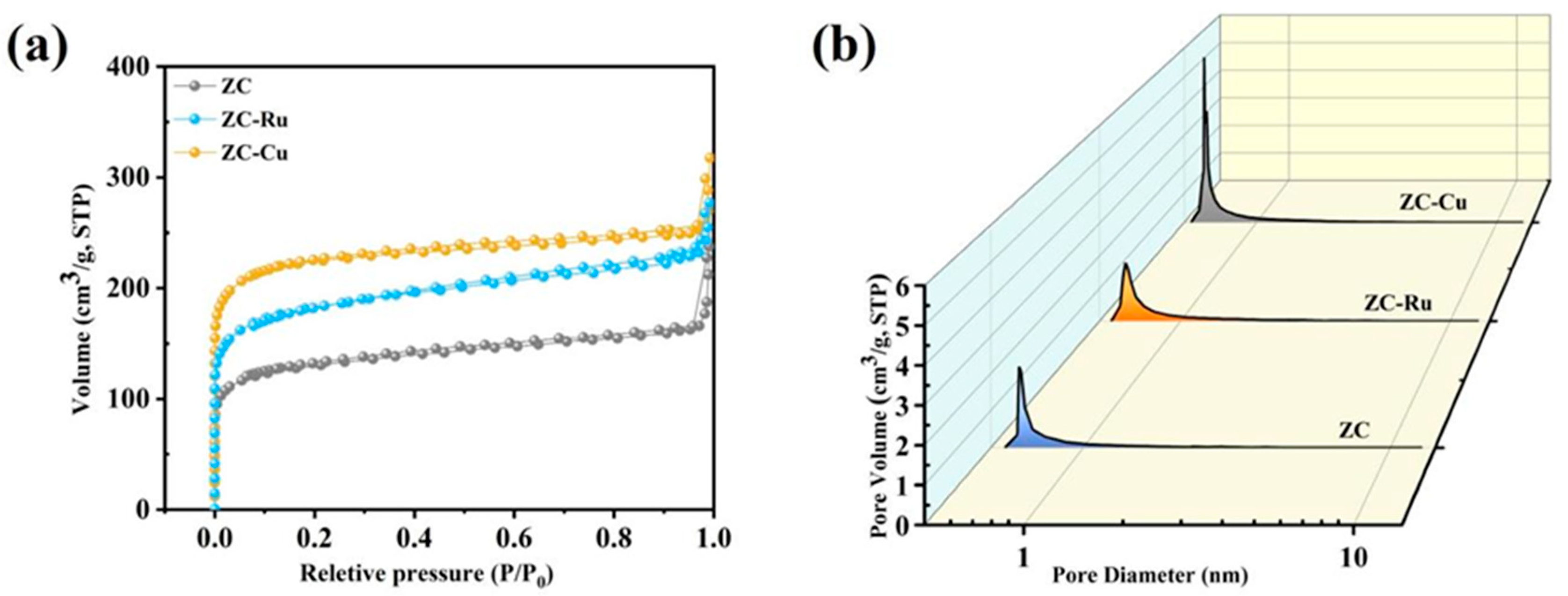
| Samples | SBET a (m2 g−1) | Smicro b (m2 g−1) | Vpore c (cm3 g−1) | Vmicro d (cm3 g−1) | Vmeso e (cm3 g−1) |
|---|---|---|---|---|---|
| ZC | 490.08 | 347.35 | 0.42 | 0.14 | 0.25 |
| ZC-Ru | 692.54 | 508.97 | 0.43 | 0.20 | 0.19 |
| ZC-Cu | 859.78 | 712.33 | 0.49 | 0.28 | 0.17 |
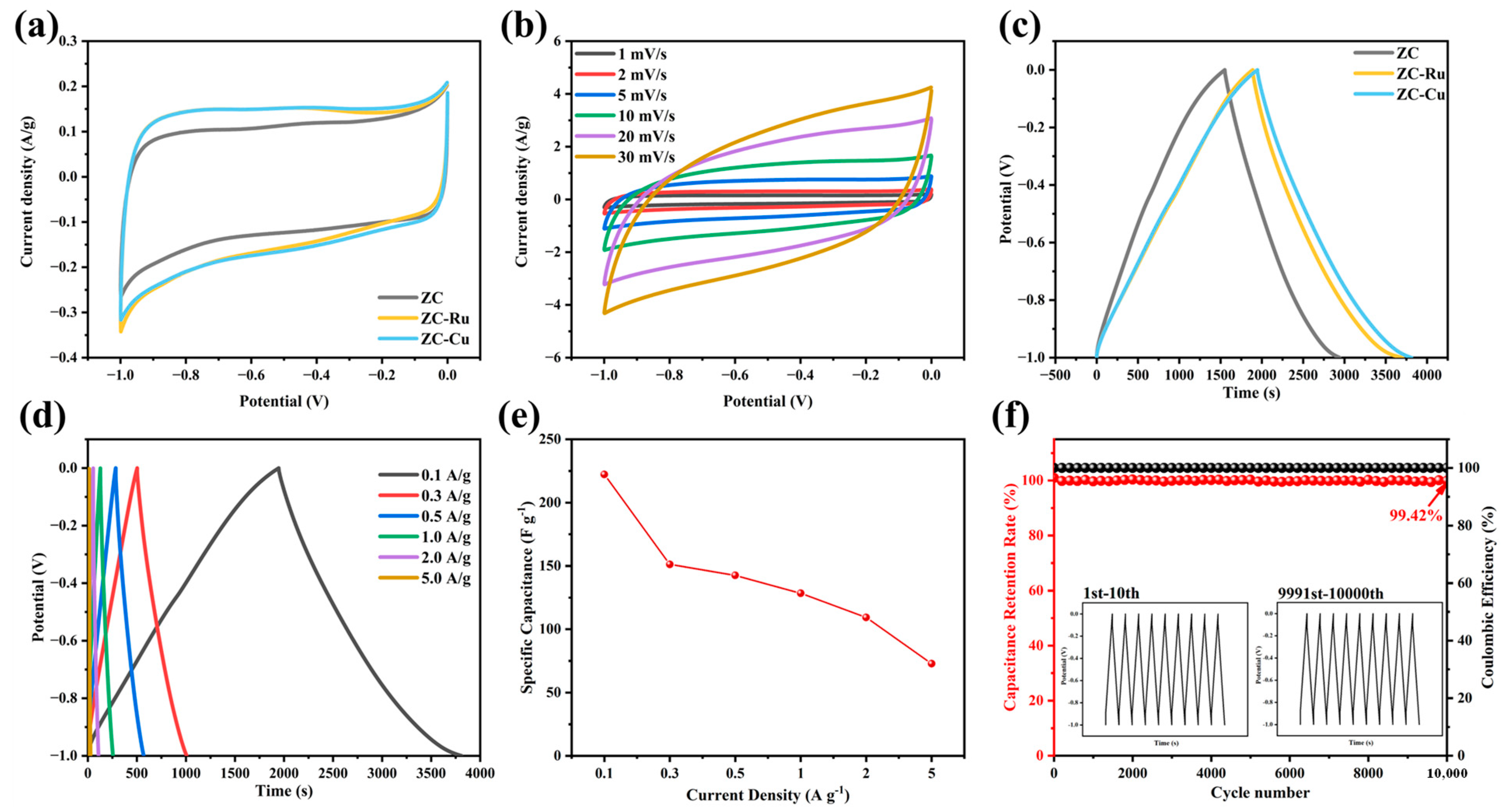
| Electrode Materials | SSA (m2 g−1) | Specific Capacitance (F g−1) | Current Density (A g−1) | Energy Density (Wh kg−1) | Power Density (W kg−1) | Cycle Stability (%) | References |
|---|---|---|---|---|---|---|---|
| ZC-Cu | 859.78 | 222.12 | 0.1 | 1.61 | 485.12 | 99.42/10,000 cycles | This work |
| Au@NCNC (nanocarbon-based material) | 420.8 | 168.6 | 1 | -- | -- | 97/5000 cycles | [40] |
| NMC-0.5 (ZIF-derived mesoporous carbon) | 2088 | 263 | 1 | 2.97 | 400 | 96.07/10,000 cycles | [58] |
| Cu-MOF | 1321 | 104.8 | 0.5 | 18.2 | 825 | 87/10,000 cycles | [34] |
| PAN/γ-CD-MOF | 134.7 | 283.3 | 0.5 | 17.5 | 600 | 97.5/6000 cycles | [59] |
Disclaimer/Publisher’s Note: The statements, opinions and data contained in all publications are solely those of the individual author(s) and contributor(s) and not of MDPI and/or the editor(s). MDPI and/or the editor(s) disclaim responsibility for any injury to people or property resulting from any ideas, methods, instructions or products referred to in the content. |
© 2024 by the authors. Licensee MDPI, Basel, Switzerland. This article is an open access article distributed under the terms and conditions of the Creative Commons Attribution (CC BY) license (https://creativecommons.org/licenses/by/4.0/).
Share and Cite
Han, X.; Geng, Y.; Wang, J.; Zhang, S.; Wei, C.; Cao, L.; Zhang, S. ZIF-8-Based Nitrogen and Monoatomic Metal Co-Doped Pyrolytic Porous Carbon for High-Performance Supercapacitor Applications. Nanomaterials 2024, 14, 1367. https://doi.org/10.3390/nano14161367
Han X, Geng Y, Wang J, Zhang S, Wei C, Cao L, Zhang S. ZIF-8-Based Nitrogen and Monoatomic Metal Co-Doped Pyrolytic Porous Carbon for High-Performance Supercapacitor Applications. Nanomaterials. 2024; 14(16):1367. https://doi.org/10.3390/nano14161367
Chicago/Turabian StyleHan, Xiaobo, Yihao Geng, Jieni Wang, Shuqin Zhang, Chenlin Wei, Leichang Cao, and Shicheng Zhang. 2024. "ZIF-8-Based Nitrogen and Monoatomic Metal Co-Doped Pyrolytic Porous Carbon for High-Performance Supercapacitor Applications" Nanomaterials 14, no. 16: 1367. https://doi.org/10.3390/nano14161367