
Ferroelectric and Non-Linear Optical Nanofibers by Electrospinning: From Inorganics to Molecular Crystals


Abstract
:1. Introduction
2. Electrospinning Process and Parameters
2.1. Electrospinning
2.2. Process Parameters
3. Composite Ferroelectric and Multiferroic Fibers with Inorganic Inclusions
3.1. Ferroelectric Polymers
3.2. Electrospinning-Assisted Ferroelectric Inorganic Nanofibers
3.3. Electrospinning-Assisted Multiferroic Nanofibers
3.3.1. Core–Shell Multiferroic Fibers

| Polymer | Core–Shell Fibers | Heat Treatment | Magnetoelectric Coefficient | Ref. |
|---|---|---|---|---|
| PVP for CFO Mw = 1,300,000 PMMA for PZT Mw = 120,000 | CoFe2O4–Pb(Zr0.52Ti0.48)O3 CFO–PZT | Nanofibers were collected on Pt/Ti/SiO2/Si substrates and dried at 120 °C for 4 h, followed by heating at 400 °C and then thermal annealing at 750 °C for 2 h in air | α31 = 29.5 V/cmOe | [126] |
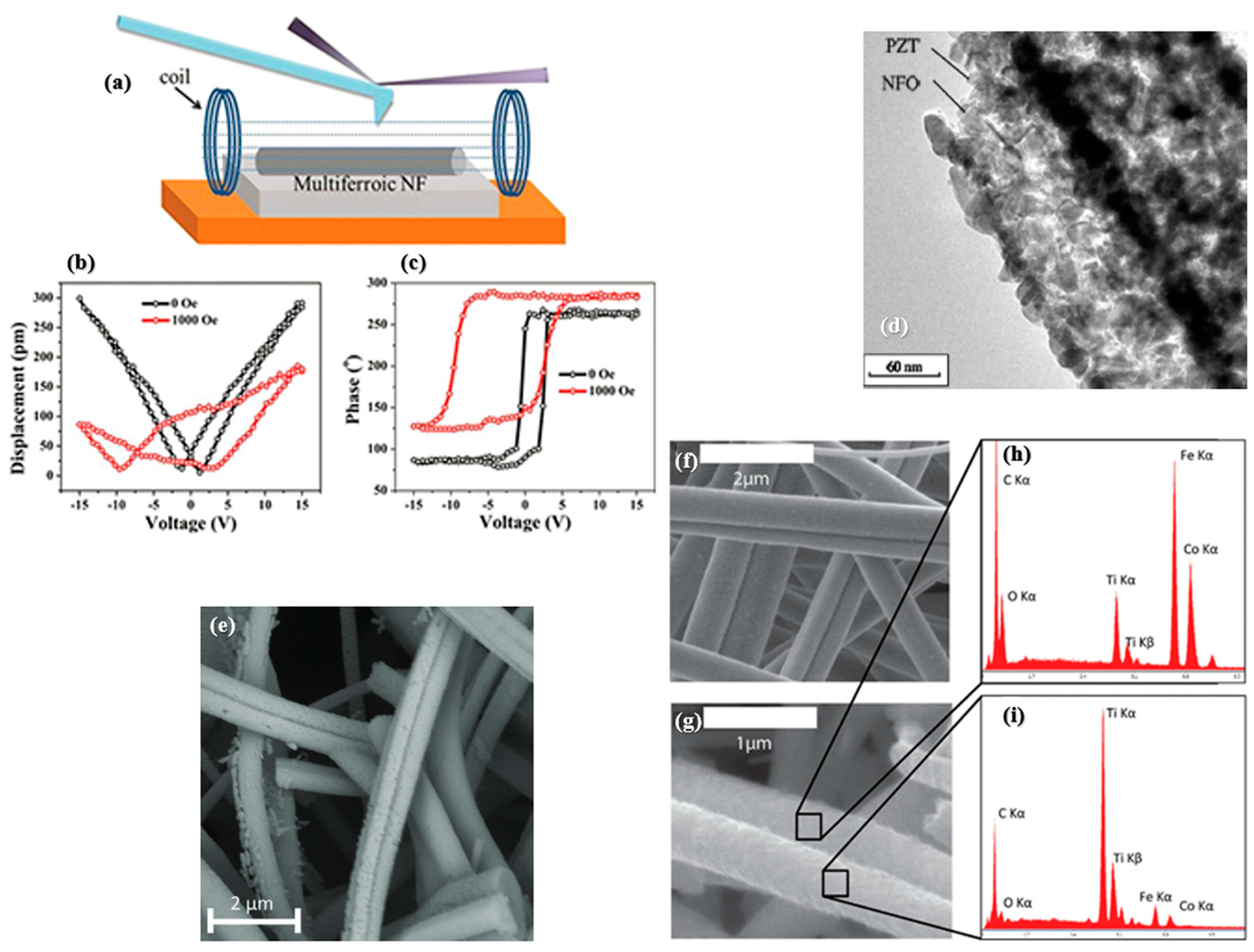
| PVP for NFO and PZT Mw = 1,300,000 | NiFe2O4–Pb(Zr0.52Ti0.48)O3 NFO–PZT | Fibers dried at 40 °C for 24 h and annealed in air at 650 °C for 1 h | Av = δHr /V Av = −24 Oe/V Converse effect, @ 5.4 GHz [85] MD = Δε′/ε′ MD = 8% (unassembled), −2% (assembled in magnetic field) @ 20–22 GHz, H = 0.8 T [127] | [124,127] |
| PVP for NDO Mw = 1,300,000 PVA for PZT Mw = 50,000 | NdFeO3–Pb(Zr0.52Ti0.48)O3 NDO–PZT | Nanofibers were kept on a hot plate to dry at 100 for 10 h, followed by annealing at 850 C for 8 h. | - | [128] |
| PVP for CFO and BFO | CoFe2O4–BiFeO3 CFO–BFO | Nanofibers were collected to Pt/Ti/SiO2/Si substrates and dried at 120 °C for 4 h, followed by thermal annealing at 750 °C for 2 h in air. | 220–250 V/cm Oe - | [129] |
| PVP Mw = 1,300,000 For NFO and BFO | NiFe2O4–BiFeO3 NFO–BFO | The samples were dried at 80 °C for 8 h, calcined at 350 °C for 2 h, and then calcined at 700 °C for 4 h in air. | - | [130] |
| PVP Mw = 1,300,000 For NFO and BTO | NiFe2O4–BaTiO3 NFO–BTO | Dried in an oven at 40 °C for 24 h, and then annealed for 1 h at 600–700 °C in air | 0.4 mV/cm Oe @ 30 Hz | [131] |
| PVP for CFO and BCZT | CoFe2O4–Ba(Zr0.2Ti0.8)O3–0.5(Ba0.7Ca0.3)TiO3 (CFO–BCZT) | Dried at 120 °C for 90 min and calcined at temperatures of between 700 °C and 1000 °C for 1 h | - | [132] |
| PVP for BNFO and PZT | Ba2Ni2Fe12O22–Pb(Zr0.52Ti0.48)O3 BNFO–PZT | Dried on a hot plate at 100 °C for 6 h and then annealed at 1100 °C for 6 h | MD = Δε′/ε′ MD = –2.4% @ 100 Hz, H = 0.6 T | [133] |
| PVP for CFO and BCTSO | CoFe2O4–Ba0.95Ca0.05Ti0.89Sn0.11O3 CFO–BCTSO | Fibers dried at 80 °C under vacuum for 12 h and then annealed at 700 °C for 4 h in air | α = 0.346 V/cm Oe @ H = 1 T | [134] |
3.3.2. Composite and Janus Multiferroic Fibers
| Polymer | Composite and Janus Fibers | Heat Treatments | Magnetoelectric Coefficient | Ref. |
|---|---|---|---|---|
| PVP Mw = 1,300,000 | Ni0.8Zn0.2Fe2O4–Ba0.7Sr0.3TiO3 NZFO–BSTO composite fibers | Composite BSTO/NZFO fibers with molar ratios of 95/5, 90/10, 80/20, and 70/30 were annealed at 700 °C for 2 h. | MD = Δε′/ε′ MD ~18.2% @ 1 kHz, H = 6.3 kOe | [135] |
| PVP | CoFe2O4–BaTiO3 CFO–BTO composite fibers | Composite CFO/BTO fibers with a molar ratio of 50/50 were dried in an oven at 120 °C for 8 h, followed by annealing at 700 °C for 2 h. | α31 = 7.8 V/cmOe | [136] |
| PVP Mw = 1,300,000 | CoFe2O4–Pb(Zr0.52Ti0.48)O3 CFO–PZT composite fibers | Composite CFO/PZT fibers with molar ratios of 0.75:1, 1:1, and 1.25:1 were dried at 120 °C for 4 h, followed by heating at 400 °C and then annealing at 550 °C for 2 h in air. | - | [137,138] |
| PVP Mw = 1,300,000 | NiFe2O4–Pb(Zr0.52Ti0.48)O3 NFO–PZT composite fibers | Composite NFO/PZT fibers with molar ratios of 0.75:1, 1:1, and 1.25:1 were dried at 120 °C for 4 h, followed by heating at 400 °C and then annealing at 550 °C for 2 h in air. | - | [139] |
| PVP Mw = 1,300,000 | CoFe2O4–(Ba0.95Ca0.05)(Ti0.89Sn0.11)O3 CFO–BCTSO composite fibers | Composite BCTSn/CFO fibers with a 1:1 molar ratio were dried at 80 °C under vacuum for 12 h before being annealed at 700 °C for 4 h in air. | - | [140] |
| PVP Mw = 1,300,000 | CoFe2O4–BiFeO3 CFO–BFO composite fibers | Nanofibers with molar ratios of 1:0, 1:0.5, 1:1, 1:1.5, and 0:1 were dried at 60 °C for 12 h, followed by heating at 400 °C for 1.5 h and then annealing at 600 °C for 2 h in air. | - | [141] |
| PVP Mw = 1,300,000 | CoFe2O4–BaTiO3 CFO–BTO Janus fibers | The fibers were calcined at 750 °C for 2 h. | Changes in magnetization at the BTO ferroelectric Curie temperature [23,142,143]; MOKE [144] Magnetic field-dependent polarization-resolved SHG [145] | [23,142,143,144,145,146] |
4. Composite Fibers with Organic Ferroelectric Crystals
5. Nonlinear Optical Nanofibers
6. Perspectives for Applications: Stability, Biocompatibility, Scalability, and Environmental Impact
6.1. Long-Term Stability
6.2. Biocompatibility
6.3. Scalability of Production
6.4. Environmental Impact
7. Conclusions
Author Contributions
Funding
Acknowledgments
Conflicts of Interest
References
- Sekhar, M.C.; Veena, E.; Kumar, N.S.; Naidu, K.C.B.; Mallikarjuna, A.; Basha, D.B. A review on piezoelectric materials and their applications. Cryst. Res. Technol. 2023, 58, 2200130. [Google Scholar] [CrossRef]
- Lines, M.E.; Glass, A.M. Principles and Applications of Ferroelectrics and Related Materials; Oxford University Press: Oxford, UK, 2001. [Google Scholar]
- Setter, N.; Damjanovic, D.; Eng, L.; Fox, G.; Gevorgian, S.; Hong, S.; Kingon, A.; Kohlstedt, H.; Park, N.; Stephenson, G. Ferroelectric thin films: Review of materials, properties, and applications. J. Appl. Phys. 2006, 100, 051606. [Google Scholar]
- Zhang, D.; Wu, H.; Bowen, C.R.; Yang, Y. Recent advances in pyroelectric materials and applications. Small 2021, 17, 2103960. [Google Scholar] [CrossRef]
- Chen, X.; Xu, S.; Yao, N.; Shi, Y. 1.6 V Nanogenerator for Mechanical Energy Harvesting Using PZT Nanofibers. Nano Lett. 2010, 10, 2133–2137. [Google Scholar] [CrossRef]
- Shi, Q.; Wang, T.; Lee, C. MEMS based broadband piezoelectric ultrasonic energy harvester (PUEH) for enabling self-powered implantable biomedical devices. Sci. Rep. 2016, 6, 24946. [Google Scholar] [CrossRef]
- Todaro, M.T.; Guido, F.; Mastronardi, V.; Desmaele, D.; Epifani, G.; Algieri, L.; De Vittorio, M. Piezoelectric MEMS vibrational energy harvesters: Advances and outlook. Microelectron. Eng. 2017, 183, 23–36. [Google Scholar] [CrossRef]
- Meng, C.; Thrane, P.C.; Ding, F.; Bozhevolnyi, S.I. Full-range birefringence control with piezoelectric MEMS-based metasurfaces. Nat. Commun. 2022, 13, 2071. [Google Scholar] [CrossRef]
- Scott, J. Applications of modern ferroelectrics. Science 2007, 315, 954–959. [Google Scholar] [CrossRef]
- Scott, J.F. Applications of magnetoelectrics. J. Mater. Chem. 2012, 22, 4567–4574. [Google Scholar] [CrossRef]
- Martin, L.W.; Rappe, A.M. Thin-film ferroelectric materials and their applications. Nat. Rev. Mater. 2016, 2, 16087. [Google Scholar] [CrossRef]
- Mikolajick, T.; Schroeder, U.; Slesazeck, S. The past, the present, and the future of ferroelectric memories. IEEE Trans. Electron. Dev. 2020, 67, 1434–1443. [Google Scholar] [CrossRef]
- Lim, H.E.; Nakanishi, Y.; Liu, Z.; Pu, J.; Maruyama, M.; Endo, T.; Ando, C.; Shimizu, H.; Yanagi, K.; Okada, S. Wafer-Scale Growth of One-Dimensional Transition-Metal Telluride Nanowires. Nano Lett. 2020, 21, 243–249. [Google Scholar] [CrossRef]
- Varghese, J.; O’Regan, C.; Deepak, N.; Whatmore, R.W.; Holmes, J.D. Surface roughness assisted growth of vertically oriented ferroelectric SbSI nanorods. Chem. Mater. 2012, 24, 3279–3284. [Google Scholar] [CrossRef]
- Ji, S.; Liu, H.; Sang, Y.; Liu, W.; Yu, G.; Leng, Y. Synthesis, structure, and piezoelectric properties of ferroelectric and antiferroelectric NaNbO3 nanostructures. Crystengcomm 2014, 16, 7598–7604. [Google Scholar] [CrossRef]
- Buscaglia, M.T.; Sennour, M.; Buscaglia, V.; Bottino, C.; Kalyani, V.; Nanni, P. Formation of Bi4Ti3O12 one-dimensional structures by solid-state reactive diffusion. From core− shell templates to nanorods and nanotubes. Cryst. Growth. Des. 2011, 11, 1394–1401. [Google Scholar] [CrossRef]
- Yang, P.; Ding, Y.; Lin, Z.; Chen, Z.; Li, Y.; Qiang, P.; Ebrahimi, M.; Mai, W.; Wong, C.P.; Wang, Z.L. Low-cost high-performance solid-state asymmetric supercapacitors based on MnO2 nanowires and Fe2O3 nanotubes. Nano lett. 2014, 14, 731–736. [Google Scholar] [CrossRef] [PubMed]
- Kim, J.; Yang, S.A.; Choi, Y.C.; Han, J.K.; Jeong, K.O.; Yun, Y.J.; Kim, D.J.; Yang, S.M.; Yoon, D.; Cheong, H. Ferroelectricity in highly ordered arrays of ultra-thin-walled Pb(Zr,Ti)O3 nanotubes composed of nanometer-sized perovskite crystallites. Nano Lett. 2008, 8, 1813–1818. [Google Scholar] [CrossRef]
- Wang, W.; Ke, H.; Rao, J.-C.; Feng, M.; Zhou, Y. Sol–Gel synthesis of SrBi2Ta2O9 nanowires. J. Alloy Compd. 2010, 504, 367–370. [Google Scholar] [CrossRef]
- Karvounis, A.; Timpu, F.; Vogler-Neuling, V.V.; Savo, R.; Grange, R. Barium titanate nanostructures and thin films for photonics. Adv. Opt. Mater. 2020, 8, 2001249. [Google Scholar] [CrossRef]
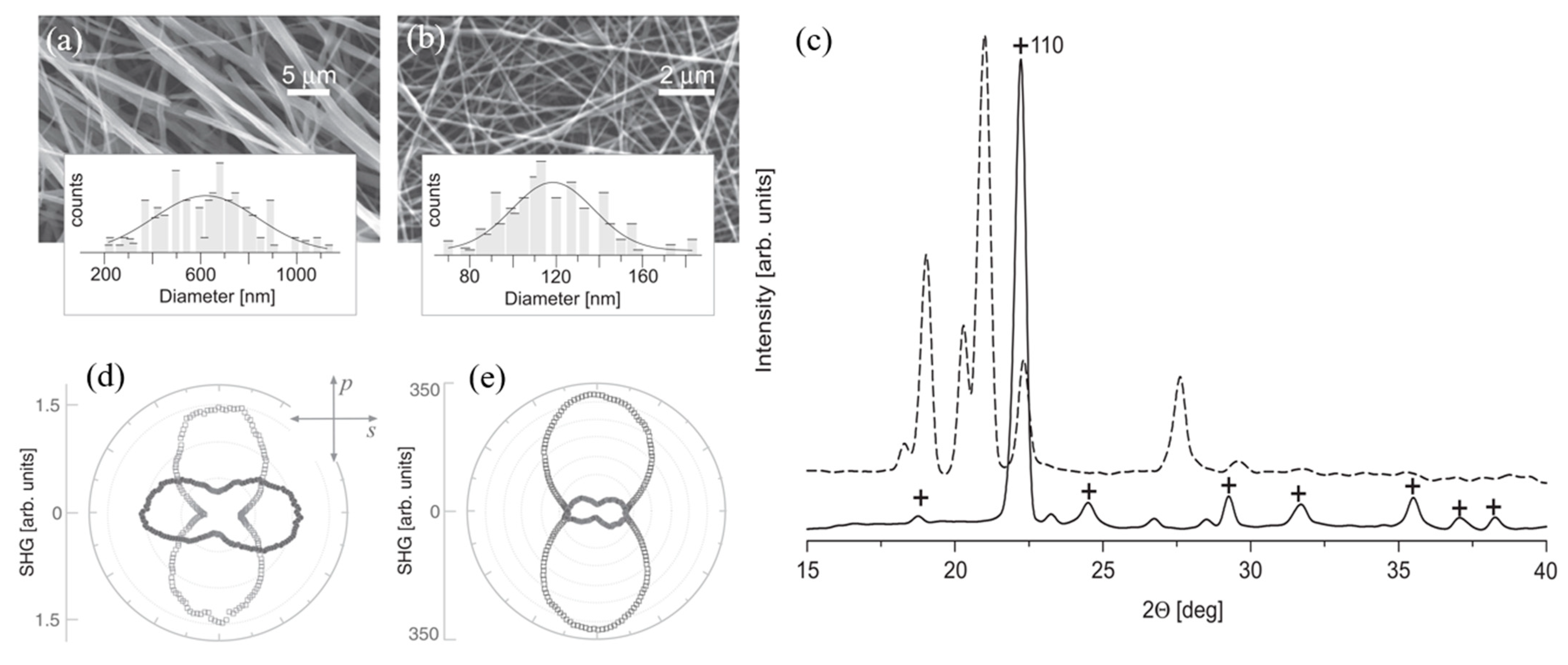
- Isakov, D.V.; de Matos Gomes, E.; Vieira, L.G.; Dekola, T.; Belsley, M.S.; Almeida, B.G. Oriented single-crystal-like molecular arrangement of optically nonlinear 2-methyl-4-nitroaniline in electrospun nanofibers. ACS Nano 2011, 5, 73–78. [Google Scholar] [CrossRef]
- Wendorff, J.H.; Agarwal, S.; Greiner, A. Electrospinning: Materials, Processing, and Applications; John Wiley & Sons: Hoboken, NJ, USA, 2012. [Google Scholar]
- Starr, J.D.; Andrew, J.S. Janus-type bi-phasic functional nanofibers. Chem. Commun. 2013, 49, 4151–4153. [Google Scholar] [CrossRef] [PubMed]
- Isakov, D.; Gomes, E.D.; Almeida, B.; Kholkin, A.L.; Zelenovskiy, P.; Neradovskiy, M.; Shur, V.Y. Energy harvesting from nanofibers of hybrid organic ferroelectric dabcoHReO4. Appl. Phys. Lett. 2014, 104, 4. [Google Scholar] [CrossRef]
- Sun, B.; Long, Y.Z.; Zhang, H.D.; Li, M.M.; Duvail, J.L.; Jiang, X.Y.; Yin, H.L. Advances in three-dimensional nanofibrous macrostructures via electrospinning. Prog. Polym. Sci. 2014, 39, 862–890. [Google Scholar] [CrossRef]
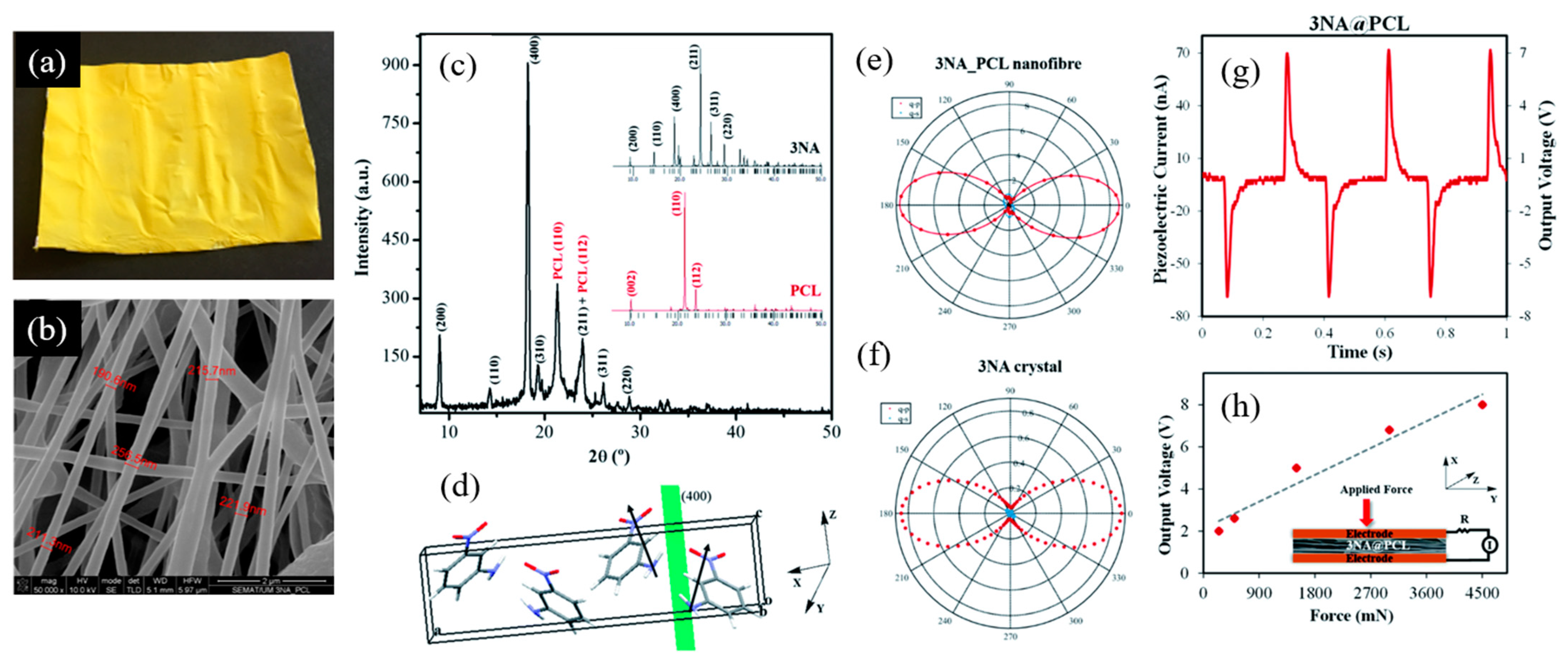
- Bernardo, C.R.; Baptista, R.M.F.; de Matos Gomes, E.; Lopes, P.E.; Raposo, M.M.M.; Costa, S.P.G.; Belsley, M.S. Anisotropic PCL nanofibers embedded with nonlinear nanocrystals as strong generators of polarized second harmonic light and piezoelectric currents. Nanoscale Adv. 2020, 2, 1206–1213. [Google Scholar] [CrossRef] [PubMed]
- Laramée, A.W.; Lanthier, C.; Pellerin, C. Electrospinning of Highly Crystalline Polymers for Strongly Oriented Fibers. ACS Appl. Polym. Mater. 2020, 2, 5025–5032. [Google Scholar] [CrossRef]
- Greiner, A.; Wendorff, J.H. Electrospinning: A Fascinating Method for the Preparation of Ultrathin Fibers. Angew. Chem. Int. Ed. 2007, 46, 5670–5703. [Google Scholar] [CrossRef]
- Ramakrishna, S.; Fujihara, K.; Teo, W.-E.; Yong, T.; Ma, Z.; Ramaseshan, R. Electrospun nanofibers: Solving global issues. Mater. Today 2006, 9, 40–50. [Google Scholar] [CrossRef]
- Ramakrishna, S.; Fujihara, K.; Teo, W.-E.; Lim, T.-C.; Ma, Z. An Introduction to Electrospinning and Nanofibers; World Scientific: Singapore, 2005; p. 396. [Google Scholar]
- Li, D.; Xia, Y. Electrospinning of Nanofibers: Reinventing the Wheel? Adv. Mater. 2004, 16, 1151–1170. [Google Scholar] [CrossRef]
- Huang, Z.-M.; Zhang, Y.Z.; Kotaki, M.; Ramakrishna, S. A review on polymer nanofibers by electrospinning and their applications in nanocomposites. Compos. Sci. Technol. 2003, 63, 2223–2253. [Google Scholar] [CrossRef]
- Sun, Y.; Cheng, S.; Lu, W.; Wang, Y.; Zhang, P.; Yao, Q. Electrospun fibers and their application in drug controlled release, biological dressings, tissue repair, and enzyme immobilization. RSC Adv. 2019, 9, 25712–25729. [Google Scholar] [CrossRef]
- Blachowicz, T.; Ehrmann, A. Conductive electrospun nanofiber mats. Materials 2019, 13, 152. [Google Scholar] [CrossRef]
- Rathore, P.; Schiffman, J.D. Beyond the single-nozzle: Coaxial electrospinning enables innovative nanofiber chemistries, geometries, and applications. ACS Appl. Mater. Inter. 2020, 13, 48–66. [Google Scholar] [CrossRef] [PubMed]
- Oh, H.J.; Yeang, B.J.; Park, Y.K.; Choi, H.J.; Kim, J.H.; Kang, Y.S.; Bae, Y.; Kim, J.Y.; Lim, S.J.; Lee, W. Washable colorimetric nanofiber nonwoven for ammonia gas detection. Polymers 2020, 12, 1585. [Google Scholar] [CrossRef] [PubMed]
- Fasano, V.; Polini, A.; Morello, G.; Moffa, M.; Camposeo, A.; Pisignano, D. Bright light emission and waveguiding in conjugated polymer nanofibers electrospun from organic salt added solutions. Macromolecules 2013, 46, 5935–5942. [Google Scholar] [CrossRef] [PubMed]
- Morello, G.; Polini, A.; Girardo, S.; Camposeo, A.; Pisignano, D. Enhanced emission efficiency in electrospun polyfluorene copolymer fibers. Appl. Phys. Lett. 2013, 102, 211911. [Google Scholar] [CrossRef]
- Prateek; Thakur, V.K.; Gupta, R.K. Recent progress on ferroelectric polymer-based nanocomposites for high energy density capacitors: Synthesis, dielectric properties, and future aspects. Chem. Rev. 2016, 116, 4260–4317. [Google Scholar] [CrossRef]
- Habib, M.; Lantgios, I.; Hornbostel, K. A review of ceramic, polymer and composite piezoelectric materials. J. Phys. D: Appl. Phys. 2022, 55, 423002. [Google Scholar] [CrossRef]
- Wang, X.; Fan, J.; Manikandan, M.; Zhang, B.; Guo, J.; Chen, J.; Yang, F.; Zheng, M.; Zhang, H.; Hou, M. Recent advances in composite films of lead-free ferroelectric ceramics and poly (vinylidene fluoride)(PVDF) for energy storage capacitor: A review. J. Mater. Sci. 2023, 58, 124–143. [Google Scholar] [CrossRef]
- Pal, S.; Sarath, N.; Priya, K.S.; Murugavel, P. A review on ferroelectric systems for next generation photovoltaic applications. J. Phys. D: Appl. Phys. 2022, 55, 283001. [Google Scholar] [CrossRef]
- Jayakrishnan, A.R.; Kumar, A.; Druvakumar, S.; John, R.; Sudeesh, M.; Puli, V.S.; Silva, J.P.; Gomes, M.J.; Sekhar, K.C. Inorganic ferroelectric thin films and their composites for flexible electronic and energy device applications: Current progress and perspectives. J. Mater. Chem. C 2023, 11, 827–858. [Google Scholar] [CrossRef]
- Bakhtiar, S.U.H.; abbas Hussain, S.; Ali, S.; Ismail, A.; Zada, A.; Sattar, H.; Raziq, F.; Zahid, M.; Al-Fatesh, A.S.; Dong, W. Innovative Perspectives on Porous Ferroelectric Ceramics and their Composites: Charting New Frontiers in Energy Applications. Mater. Today Commun. 2024, 38, 108388. [Google Scholar] [CrossRef]
- Wang, Z.L. Nanogenerators and piezotronics: From scientific discoveries to technology breakthroughs. MRS Bull. 2023, 48, 1014–1025. [Google Scholar] [CrossRef]
- Ren, K.; Shen, Y.; Wang, Z.L. Piezoelectric Properties of Electrospun Polymer Nanofibers and Related Energy Harvesting Applications. Macromol. Mater. Eng. 2024, 309, 2300307. [Google Scholar] [CrossRef]
- Arica, T.A.; Isık, T.; Guner, T.; Horzum, N.; Demir, M.M. Advances in Electrospun Fiber-Based Flexible Nanogenerators for Wearable Applications. Macromol. Mater. Eng. 2021, 306, 2100143. [Google Scholar] [CrossRef]
- Starr, J.D.; Andrew, J.S. A route to synthesize multifunctional tri-phasic nanofibers. J. Mater. Chem. C 2013, 1, 2529–2533. [Google Scholar] [CrossRef]
- Koka, A.; Sodano, H.A. High-sensitivity accelerometer composed of ultra-long vertically aligned barium titanate nanowire arrays. Nat. Commun. 2013, 4, 2682. [Google Scholar] [CrossRef]
- Jiang, Y.; Zhou, M.; Shen, Z.; Zhang, X.; Pan, H.; Lin, Y.-H. Ferroelectric polymers and their nanocomposites for dielectric energy storage applications. APL Mater. 2021, 9, 020905. [Google Scholar] [CrossRef]
- Kim, H.-Y.; Lee, M.; Park, K.J.; Kim, S.; Mahadevan, L. Nanopottery: Coiling of Electrospun Polymer Nanofibers. Nano Lett. 2010, 10, 2138–2140. [Google Scholar] [CrossRef]
- Luo, G.; Teh, K.S.; Liu, Y.; Zang, X.; Wen, Z.; Lin, L. Direct-Write, Self-Aligned Electrospinning on Paper for Controllable Fabrication of Three-Dimensional Structures. ACS Appl. Mater. Inter. 2015, 7, 27765–27770. [Google Scholar] [CrossRef] [PubMed]
- Cai, M.Q.; Zheng, Y.; Wang, B.; Yang, G.W. Nanosize confinement induced enhancement of spontaneous polarization in a ferroelectric nanowire. Appl. Phys. Lett. 2009, 95, 232901. [Google Scholar] [CrossRef]
- Wang, Z.; Hu, J.; Suryavanshi, A.P.; Yum, K.; Yu, M.-F. Voltage Generation from Individual BaTiO3 Nanowires under Periodic Tensile Mechanical Load. Nano Lett. 2007, 7, 2966–2969. [Google Scholar] [CrossRef]
- Wang, W.; Li, J.; Liu, H.; Ge, S. Advancing Versatile Ferroelectric Materials Toward Biomedical Applications. Adv. Sci. 2021, 8, 2003074. [Google Scholar] [CrossRef] [PubMed]
- Koka, A.; Zhou, Z.; Sodano, H.A. Vertically aligned BaTiO3 nanowire arrays for energy harvesting. Energy Environ. Sci. 2014, 7, 288–296. [Google Scholar] [CrossRef]
- Zhou, Z.; Tang, H.; Sodano, H.A. Vertically Aligned Arrays of BaTiO3 Nanowires. ACS Appl. Mater. Inter. 2013, 5, 11894–11899. [Google Scholar] [CrossRef] [PubMed]
- Baji, A.; Mai, Y.-W.; Li, Q.; Liu, Y. Electrospinning induced ferroelectricity in poly(vinylidene fluoride) fibers. Nanoscale 2011, 3, 3068–3071. [Google Scholar] [CrossRef]
- Noyori, M.; Neo, Y.; Mimura, H. Single-crystalline poly(vinylidene fluoride–trifluoroethylene) nanofiber webs fabricated by electrospinning. Jpn. J. Appl. Phys. 2015, 54, 021601. [Google Scholar] [CrossRef]
- Xin, Y.; Zhu, J.; Sun, H.; Xu, Y.; Liu, T.; Qian, C. A brief review on piezoelectric PVDF nanofibers prepared by electrospinning. Ferroelectrics 2018, 526, 140–151. [Google Scholar] [CrossRef]
- He, Z.; Rault, F.; Lewandowski, M.; Mohsenzadeh, E.; Salaün, F. Electrospun PVDF nanofibers for piezoelectric applications: A review of the influence of electrospinning parameters on the β phase and crystallinity enhancement. Polymers 2021, 13, 174. [Google Scholar] [CrossRef]
- Liu, Y.; Zhang, Y.; Chow, M.-J.; Chen, Q.N.; Li, J. Biological ferroelectricity uncovered in aortic walls by piezoresponse force microscopy. Phys. Rev. Lett. 2012, 108, 078103. [Google Scholar] [CrossRef]
- Liu, Y.; Wang, Y.; Chow, M.-J.; Chen, N.Q.; Ma, F.; Zhang, Y.; Li, J. Glucose suppresses biological ferroelectricity in aortic elastin. Phys. Rev. Lett. 2013, 110, 168101. [Google Scholar] [CrossRef]
- Coste, B.; Xiao, B.; Santos, J.S.; Syeda, R.; Grandl, J.; Spencer, K.S.; Kim, S.E.; Schmidt, M.; Mathur, J.; Dubin, A.E. Piezo proteins are pore-forming subunits of mechanically activated channels. Nature 2012, 483, 176–181. [Google Scholar] [CrossRef] [PubMed]
- Liu, Y.; Cai, H.-L.; Zelisko, M.; Wang, Y.; Sun, J.; Yan, F.; Ma, F.; Wang, P.; Chen, Q.N.; Zheng, H. Ferroelectric switching of elastin. Proc. Natl. Acad. Sci. USA 2014, 111, E2780–E2786. [Google Scholar] [CrossRef]
- Balizer, E.; Fedderly, J.; Haught, D.; Dickens, B.; Dereggi, A. FTIR and X-ray study of polymorphs of nylon 11 and relation to ferroelectricity. J. Polym. Sci. Part B Polym. Phys. 1994, 32, 365–369. [Google Scholar] [CrossRef]
- Itoh, T.; Tanaka, T.; Hashimoto, M.; Takashi Konishi, T.K. Ferroelectric Hysteresis Behavior and Structural Property of Even-Numbered Nylon Film. Jpn. J. Appl. Phys. 1995, 34, 6164. [Google Scholar] [CrossRef]
- Capsal, J.-F.; Dantras, E.; Dandurand, J.; Lacabanne, C. Dielectric relaxations and ferroelectric behaviour of even–odd polyamide PA 6,9. Polymer 2010, 51, 4606–4610. [Google Scholar] [CrossRef]
- Murata, Y.; Tsunashima, K.; Umemura, J.; Koizumi, N. Ferroelectric properties of polyamides consisting of hepta- and nonamethylenediamines. IEEE Trans. Dielectr. Electr. Insul. 1998, 5, 96–102. [Google Scholar] [CrossRef]
- Wu, J.; Fu, Y.; Hu, G.-H.; Wang, S.; Xiong, C. Effect of Stretching on Crystalline Structure, Ferroelectric and Piezoelectric Properties of Solution-Cast Nylon-11 Films. Polymers 2021, 13, 2037. [Google Scholar] [CrossRef]
- Eom, K.; Na, S.; Kim, J.-K.; Ko, H.; Jin, J.; Kang, S.J. Engineering crystal phase of Nylon-11 films for ferroelectric device and piezoelectric sensor. Nano Energy 2021, 88, 106244. [Google Scholar] [CrossRef]
- Prasad, G.; Graham, S.A.; Yu, J.S.; Kim, H.; Lee, D.-W. Investigated a PLL surface-modified Nylon 11 electrospun as a highly tribo-positive frictional layer to enhance output performance of triboelectric nanogenerators and self-powered wearable sensors. Nano Energy 2023, 108, 108178. [Google Scholar] [CrossRef]
- Tu, N.D.K.; Park, J.; Na, S.; Kim, K.M.; Kwon, T.-H.; Ko, H.; Kang, S.J. Co-solvent induced piezoelectric γ-phase nylon-11 separator for sodium metal battery. Nano Energy 2020, 70, 104501. [Google Scholar] [CrossRef]
- Kim, D.K.; Hwang, M.; Lagerwall, J.P.F. Liquid crystal functionalization of electrospun polymer fibers. J. Polym. Sci. Part B Polym. Phys. 2013, 51, 855–867. [Google Scholar] [CrossRef]
- Zhou, L.; Liu, S.; Miao, X.; Xie, P.; Sun, N.; Xu, Z.; Zhong, T.; Zhang, L.; Shen, Y. Advancements and Applications of Liquid Crystal/Polymer Composite Films. ACS Mater. Lett. 2023, 5, 2760–2775. [Google Scholar] [CrossRef]
- Bertocchi, M.J.; Ratchford, D.C.; Casalini, R.; Wynne, J.H.; Lundin, J.G. Electrospun polymer fibers containing a liquid crystal core: Insights into semiflexible confinement. J. Phys. Chem. C 2018, 122, 16964–16973. [Google Scholar] [CrossRef]
- Nguyen, J.; Stwodah, R.M.; Vasey, C.L.; Rabatin, B.E.; Atherton, B.; D’Angelo, P.A.; Swana, K.W.; Tang, C. Thermochromic fibers via electrospinning. Polymers 2020, 12, 842. [Google Scholar] [CrossRef] [PubMed]
- Lagerwall, J.P.; McCann, J.T.; Formo, E.; Scalia, G.; Xia, Y. Coaxial electrospinning of microfibres with liquid crystal in the core. Chem. Commun. 2008, 42, 5420–5422. [Google Scholar] [CrossRef]
- Reyes, C.G.; Sharma, A.; Lagerwall, J.P. Non-electronic gas sensors from electrospun mats of liquid crystal core fibres for detecting volatile organic compounds at room temperature. Liq. Cryst. 2016, 43, 1986–2001. [Google Scholar] [CrossRef]
- Williams, M.W.; Wimberly, J.A.; Stwodah, R.M.; Nguyen, J.; D’Angelo, P.A.; Tang, C. Temperature-Responsive Structurally Colored Fibers via Blend Electrospinning. ACS Appl. Polym. Mater. 2023, 5, 3065–3078. [Google Scholar] [CrossRef]
- Sharma, A.; Lagerwall, J.P. Electrospun composite liquid crystal elastomer fibers. Materials 2018, 11, 393. [Google Scholar] [CrossRef]
- Kularatne, R.S.; Kim, H.; Boothby, J.M.; Ware, T.H. Liquid crystal elastomer actuators: Synthesis, alignment, and applications. J. Polym. Sci. Part B Polym. Phys. 2017, 55, 395–411. [Google Scholar] [CrossRef]
- Liu, Y.; Luo, H.; Gao, Z.; Xie, H.; Guo, R.; Wang, F.; Zhou, X.; Cao, J.; Zhang, D. Electrospinning Synthesis of Na0.5Bi0.5TiO3 Nanofibers for Dielectric Capacitors in Energy Storage Application. Nanomaterials 2022, 12, 906. [Google Scholar] [CrossRef]
- Yuh, J.; Nino, J.C.; Sigmund, W.M. Synthesis of barium titanate (BaTiO3) nanofibers via electrospinning. Mater. Lett. 2005, 59, 3645–3647. [Google Scholar] [CrossRef]
- Sá, P.; Barbosa, J.; Bdikin, I.; Almeida, B.; Rolo, A.G.; Gomes, E.d.M.; Belsley, M.; Kholkin, A.L.; Isakov, D. Ferroelectric characterization of aligned barium titanate nanofibres. J. Phys. D Appl. Phys. 2013, 46, 105304. [Google Scholar] [CrossRef]
- Ganeshkumar, R.; Sopiha, K.V.; Wu, P.; Cheah, C.W.; Zhao, R. Ferroelectric KNbO3 nanofibers: Synthesis, characterization and their application as a humidity nanosensor. Nanotechnology 2016, 27, 395607. [Google Scholar] [CrossRef] [PubMed]
- Jalalian, A.; Grishin, A.M. Biocompatible ferroelectric (Na,K)NbO3 nanofibers. Appl. Phys. Lett. 2012, 100, 012904. [Google Scholar] [CrossRef]
- Chen, X.; Xu, S.; Yao, N.; Xu, W.; Shi, Y. Potential measurement from a single lead ziroconate titanate nanofiber using a nanomanipulator. Appl. Phys. Lett. 2009, 94, 253113. [Google Scholar] [CrossRef]
- Zhu, R.; Wang, Z.; Cheng, Z.; Kimura, H. Ferroelectric nanofibers and their application in energy harvesting. In Nanoscale Ferroelectric-Multiferroic Materials for Energy Harvesting Applications; Kimura, H., Cheng, Z., Jia, T., Eds.; Elsevier: Amsterdam, The Netherlands, 2019; pp. 181–194. [Google Scholar]
- Yan, J.; Jeong, Y.G. High performance flexible piezoelectric nanogenerators based on BaTiO3 nanofibers in different alignment modes. ACS Appl. Mater. Inter. 2016, 8, 15700–15709. [Google Scholar] [CrossRef]
- Zhao, Y.; Fan, H.; Liu, G.; Liu, Z.; Ren, X. Ferroelectric, piezoelectric properties and magnetoelectric coupling behavior in aurivillius Bi5Ti3FeO15 multiferroic nanofibers by electrospinning. J. Alloy Compd. 2016, 675, 441–447. [Google Scholar] [CrossRef]
- Li, B.; Wang, C.; Liu, W.; Zhong, Y.; An, R. Synthesis of Co-doped barium strontium titanate nanofibers by sol–gel/electrospinning process. Mater. Lett. 2012, 75, 207–210. [Google Scholar] [CrossRef]
- Wang, Y.; Santiago-Avilés, J.J. A Review on Synthesis and Characterization of Lead Zirconate Titanate Nanofibers through Electrospinning. Integr. Ferroelectr. 2011, 126, 60–76. [Google Scholar] [CrossRef]
- Yousefi, F.; Esfahani, H. Role of Nb5+-Nd3+ co-dopant in morphotropic boundary of electrospun PZT nanoneedles: Study on dielectric and piezoelectric sensitivity. J. Alloy Compd. 2023, 966, 171531. [Google Scholar] [CrossRef]
- Gu, L.; Cui, N.; Cheng, L.; Xu, Q.; Bai, S.; Yuan, M.; Wu, W.; Liu, J.; Zhao, Y.; Ma, F.; et al. Flexible Fiber Nanogenerator with 209 V Output Voltage Directly Powers a Light-Emitting Diode. Nano Lett. 2013, 13, 91–94. [Google Scholar] [CrossRef] [PubMed]
- Wu, W.; Bai, S.; Yuan, M.; Qin, Y.; Wang, Z.L.; Jing, T. Lead Zirconate Titanate Nanowire Textile Nanogenerator for Wearable Energy-Harvesting and Self-Powered Devices. ACS Nano 2012, 6, 6231–6235. [Google Scholar] [CrossRef]
- Xia, S.; Wei, C.; Zhai, Y.; Ding, B.; Yu, J.; Yan, J. Ultrasonic cavitation enhanced photocatalytic CO2 reduction by superior flexible black BaTiO3 nanofibers. Chem. Eng. J. 2023, 475, 146516. [Google Scholar] [CrossRef]
- Maensiri, S.; Nuansing, W.; Klinkaewnarong, J.; Laokul, P.; Khemprasit, J. Nanofibers of barium strontium titanate (BST) by sol–gel processing and electrospinning. J. Colloid Interface Sci. 2006, 297, 578–583. [Google Scholar] [CrossRef]
- Pan, Z.B.; Yao, L.M.; Zhai, J.W.; Liu, S.H.; Yang, K.; Wang, H.T.; Liu, J.H. Fast discharge and high energy density of nanocomposite capacitors using Ba0.6Sr0.4TiO3 nanofibers. Ceram. Int. 2016, 42, 14667–14674. [Google Scholar] [CrossRef]
- Maldonado-Orozco, M.C.; Ochoa-Lara, M.T.; Sosa-Márquez, J.E.; Olive-Méndez, S.F.; Espinosa-Magaña, F. Synthesis and characterization of electrospun LiNbO3 nanofibers. Ceram. Int. 2015, 41, 14886–14889. [Google Scholar] [CrossRef]
- Maldonado-Orozco, M.C.; Ochoa-Lara, M.T.; Sosa-Márquez, J.E.; Olive-Méndez, S.F.; Pizá-Ruiz, P.; Quintanar-Sierra, J.J.C.; Espinosa-Magaña, F. Characterization of Mn-doped electrospun LiNbO3 nanofibers by Raman spectroscopy. Mater. Charact. 2017, 127, 209–213. [Google Scholar] [CrossRef]
- Zhou, B.; Li, C.; Zhou, Y.; Liu, Z.; Gao, X.; Wang, X.; Jiang, L.; Tian, M.; Zhou, F.-L.; Jerrams, S.; et al. A flexible dual-mode pressure sensor with ultra-high sensitivity based on BTO@MWCNTs core-shell nanofibers. Compos. Sci. Technol. 2022, 224, 109478. [Google Scholar] [CrossRef]
- Ichangi, A.; Lê, K.; Queraltó, A.; Grosch, M.; Weißing, R.; Ünlü, F.; Chijioke, A.K.; Verma, A.; Fischer, T.; Surmenev, R.; et al. Electrospun BiFeO3 Nanofibers for Vibrational Energy Harvesting Application. Adv. Eng. Mater. 2022, 24, 2101394. [Google Scholar] [CrossRef]
- Fei, L.; Hu, Y.; Li, X.; Song, R.; Sun, L.; Huang, H.; Gu, H.; Chan, H.L.W.; Wang, Y. Electrospun Bismuth Ferrite Nanofibers for Potential Applications in Ferroelectric Photovoltaic Devices. ACS Appl. Mater. Inter. 2015, 7, 3665–3670. [Google Scholar] [CrossRef]
- Fourmont, P.; Nechache, R.; Cloutier, S.G. Reusable BiFeO3 Nanofiber-Based Membranes for Photo-activated Organic Pollutant Removal with Negligible Colloidal Release. ACS Appl. Nano Mater. 2021, 4, 12261–12269. [Google Scholar] [CrossRef]
- Prashanthi, K.; Shaibani, P.M.; Sohrabi, A.; Natarajan, T.S.; Thundat, T. Nanoscale magnetoelectric coupling in multiferroic BiFeO3 nanowires. Phys. Status Solidi (RRL)–Rapid Res. Lett. 2012, 6, 244–246. [Google Scholar] [CrossRef]
- Sá, P.; Bdikin, I.; Almeida, B.; Rolo, A.G.; Isakov, D. Production and PFM Characterization of Barium Titanate Nanofibers. Ferroelectrics 2012, 429, 48–55. [Google Scholar] [CrossRef]
- Wei, Y.; Song, Y.; Deng, X.; Han, B.; Zhang, X.; Shen, Y.; Lin, Y. Dielectric and ferroelectric properties of BaTiO3 nanofibers prepared via electrospinning. J. Mater. Sci. Technol. 2014, 30, 743–747. [Google Scholar] [CrossRef]
- Yan, J.; Han, Y.; Xia, S.; Wang, X.; Zhang, Y.; Yu, J.; Ding, B. Polymer template synthesis of flexible BaTiO3 crystal nanofibers. Adv. Funct. Mater. 2019, 29, 1907919. [Google Scholar] [CrossRef]
- Tang, M.; Shu, W.; Yang, F.; Zhang, J.; Dong, G.; Hou, J. The fabrication of La-substituted bismuth titanate nanofibers by electrospinning. Nanotechnology 2009, 20, 385602. [Google Scholar] [CrossRef]
- Choi, S.; Park, J.; Kang, J.; Koh, S.W.; Kang, Y.C. Synthesis and characterization of lead zirconate titanate nanofibers obtained by electrospinning. B. Kor. Chem. Soc. 2015, 36, 1594–1598. [Google Scholar] [CrossRef]
- Spaldin, N.A.; Ramesh, R. Advances in magnetoelectric multiferroics. Nat. Mater. 2019, 18, 203–212. [Google Scholar] [CrossRef]
- Leung, C.M.; Li, J.; Viehland, D.; Zhuang, X. A review on applications of magnetoelectric composites: From heterostructural uncooled magnetic sensors, energy harvesters to highly efficient power converters. J. Phys. D Appl. Phys. 2018, 51, 263002. [Google Scholar] [CrossRef]
- Hu, J.M.; Chen, L.Q.; Nan, C.W. Multiferroic heterostructures integrating ferroelectric and magnetic materials. Adv. Mater. 2016, 28, 15–39. [Google Scholar] [CrossRef]
- Hu, J.-M.; Nan, C.-W.; Chen, L.-Q. Perspective: Voltage control of magnetization in multiferroic heterostructures. Natl. Sci. Rev. 2019, 6, 621–624. [Google Scholar] [CrossRef] [PubMed]
- Lin, H.; Gao, Y.; Wang, X.; Nan, T.; Liu, M.; Lou, J.; Yang, G.; Zhou, Z.; Yang, X.; Wu, J. Integrated magnetics and multiferroics for compact and power-efficient sensing, memory, power, RF, and microwave electronics. IEEE Trans. Magn. 2016, 52, 4002208. [Google Scholar] [CrossRef]
- Manipatruni, S.; Nikonov, D.E.; Young, I.A. Beyond CMOS computing with spin and polarization. Nat. Phys. 2018, 14, 338–343. [Google Scholar] [CrossRef]
- Bichurin, M.; Petrov, R.; Sokolov, O.; Leontiev, V.; Kuts, V.; Kiselev, D.; Wang, Y. Magnetoelectric Magnetic Field Sensors: A Review. Sensors 2021, 21, 6232. [Google Scholar] [CrossRef]
- Zuo, S.; Schmalz, J.; Özden, M.Ö.; Gerken, M.; Su, J.; Niekiel, F.; Lofink, F.; Nazarpour, K.; Heidari, H. Ultrasensitive Magnetoelectric Sensing System for Pico-Tesla MagnetoMyoGraphy. IEEE Trans. Biomed. Circuits Syst. 2020, 14, 971–984. [Google Scholar] [CrossRef] [PubMed]
- Lorenz, M.; Lazenka, V.; Schwinkendorf, P.; Bern, F.; Ziese, M.; Modarresi, H.; Volodin, A.; Van Bael, M.J.; Temst, K.; Vantomme, A. Multiferroic BaTiO3–BiFeO3 composite thin films and multilayers: Strain engineering and magnetoelectric coupling. J. Phys. D Appl. Phys. 2014, 47, 135303. [Google Scholar] [CrossRef]
- Pradhan, D.K.; Kumari, S.; Rack, P.D. Magnetoelectric composites: Applications, coupling mechanisms, and future directions. Nanomaterials 2020, 10, 2072. [Google Scholar] [CrossRef]
- Andrew, J.S.; Starr, J.D.; Budi, M.A. Prospects for nanostructured multiferroic composite materials. Scr. Mater. 2014, 74, 38–43. [Google Scholar] [CrossRef]
- Zhang, C.; Chen, W.; Xie, S.; Yang, J.; Li, J. The magnetoelectric effects in multiferroic composite nanofibers. Appl. Phys. Lett. 2009, 94, 102907. [Google Scholar] [CrossRef]
- Liu, Y.; Sreenivasulu, G.; Zhou, P.; Fu, J.; Filippov, D.; Zhang, W.; Zhou, T.; Zhang, T.; Shah, P.; Page, M.R.; et al. Converse magneto-electric effects in a core–shell multiferroic nanofiber by electric field tuning of ferromagnetic resonance. Sci. Rep. 2020, 10, 20170. [Google Scholar] [CrossRef]
- Bauer, M.J.; Wen, X.; Tiwari, P.; Arnold, D.P.; Andrew, J.S. Magnetic field sensors using arrays of electrospun magnetoelectric Janus nanowires. Microsyst. Nanoeng. 2018, 4, 37. [Google Scholar] [CrossRef] [PubMed]
- Xie, S.; Ma, F.; Liu, Y.; Li, J. Multiferroic CoFe2O4–Pb(Zr0.52Ti0.48)O3 core-shell nanofibers and their magnetoelectric coupling. Nanoscale 2011, 3, 3152–3158. [Google Scholar] [CrossRef]
- Sreenivasulu, G.; Popov, M.; Zhang, R.; Sharma, K.; Janes, C.; Mukundan, A.; Srinivasan, G. Magnetic field assisted self-assembly of ferrite-ferroelectric core-shell nanofibers and studies on magneto-electric interactions. Appl. Phys. Lett. 2014, 104, 052910. [Google Scholar] [CrossRef]
- Yadav, S.K.; Hemalatha, J. Electrospinning and characterization of magnetoelectric NdFeO3–PbZr0.52Ti0.48O3 core–shell nanofibers. Ceram. Int. 2022, 48, 18415–18424. [Google Scholar] [CrossRef]
- Zhu, Q.; Xie, Y.; Zhang, J.; Liu, Y.; Zhan, Q.; Miao, H.; Xie, S. Multiferroic CoFe2O4–BiFeO3 core–shell nanofibers and their nanoscale magnetoelectric coupling. J. Mater. Res. 2014, 29, 657–664. [Google Scholar] [CrossRef]
- Li, Z.; Dai, J.; Huang, D.; Wen, X. Tuning the ferromagnetic and ferroelectric properties of BiFeO3 multiferroic nanofibers by Co/Ni spinel ferrites. J. Alloy Compd. 2022, 907, 164386. [Google Scholar] [CrossRef]
- Sreenivasulu, G.; Zhang, J.; Zhang, R.; Popov, M.; Petrov, V.; Srinivasan, G. Multiferroic Core-Shell Nanofibers, Assembly in a Magnetic Field, and Studies on Magneto-Electric Interactions. Materials 2017, 11, 18. [Google Scholar] [CrossRef]
- Molavi, A.M.; Alizadeh, P. Electrospinning of multiferroic CoFe2O4@Ba(Zr0.2Ti0.8)O3–0.5(Ba0.7Ca0.3)TiO3 nano-structured fibers via two different routes. Mater. Charact. 2021, 172, 110880. [Google Scholar] [CrossRef]
- Yadav, S.K.; Hemalatha, J. Direct magnetoelectric and magnetodielectric studies of electrospun Ba2Ni2Fe12O22–Pb(Zr0.52Ti0.48)O3 core–shell nanofibers. J. Magn. Magn. Mater. 2022, 564, 170174. [Google Scholar] [CrossRef]
- Hadouch, Y.; Mezzane, D.; Amjoud, M.b.; Laguta, V.; Hoummada, K.; Dolocan, V.O.; Jouiad, M.; Lahcini, M.; Uršič, H.; Fišinger, V.; et al. Multiferroic CoFe2O4–Ba0.95Ca0.05Ti0.89Sn0.11O3 Core–Shell Nanofibers for Magnetic Field Sensor Applications. ACS Appl. Nano Mater. 2023, 6, 10236–10245. [Google Scholar] [CrossRef]
- Li, B.; Wang, C.; Zhang, W.; Hang, C.; Fei, J.; Wang, H. Fabrication of multiferroic Ba0.7Sr0.3TiO3–Ni0.8Zn0.2Fe2O4 composite nanofibers by electrospinning. Mater. Lett. 2013, 91, 55–58. [Google Scholar] [CrossRef]
- Fu, B.; Lu, R.; Gao, K.; Yang, Y.; Wang, Y. Magnetoelectric coupling in multiferroic BaTiO3-CoFe2O4 composite nanofibers via electrospinning. Europhys. Lett. 2015, 111, 17007. [Google Scholar] [CrossRef]
- Xie, S.; Li, J.; Qiao, Y.; Liu, Y.; Lan, L.; Zhou, Y.; Tan, S. Multiferroic CoFe2O4–Pb(Zr0.52Ti0.48)O3 nanofibers by electrospinning. Appl. Phys. Lett. 2008, 92, 062901. [Google Scholar] [CrossRef]
- Zhu, Q.; Pan, K.; Xie, S.; Liu, Y.; Li, J. Nanomechanics of multiferroic composite nanofibers via local excitation piezoresponse force microscopy. J. Mech. Phys. Solids 2019, 126, 76–86. [Google Scholar] [CrossRef]
- Xie, S.; Li, J.; Liu, Y.; Lan, L.; Jin, G.; Zhou, Y. Electrospinning and multiferroic properties of NiFe2O4–Pb(Zr0.52Ti0.48)O3 composite nanofibers. J. Appl. Phys. 2008, 104, 024115. [Google Scholar] [CrossRef]
- Hadouch, Y.; Abdallah, N.; Mezzane, D.; Amjoud, M.b.; Dolocan, V.; Hoummada, K.; Novak, N.; Razumnaya, A.; Rozic, B.; Fisinger, V. Multiferroic properties of electrospun CoFe2O4–(Ba0.95Ca0.05)(Ti0.89Sn0.11)O3 nanocomposites for magnetoelectric and magnetic field sensing applications. J. Mater. Sci. Mater. Electron. 2024, 35, 1794. [Google Scholar] [CrossRef]
- An, F.; Zhong, G.; Zhu, Q.; Huang, Y.; Yang, Y.; Xie, S. Synthesis and mechanical properties characterization of multiferroic BiFeO3-CoFe2O4 composite nanofibers. Ceram. Int. 2018, 44, 11617–11621. [Google Scholar] [CrossRef]
- Liu, Z.; Sun, D.D.; Guo, P.; Leckie, J.O. An efficient bicomponent TiO2/SnO2 nanofiber photocatalyst fabricated by electrospinning with a side-by-side dual spinneret method. Nano lett. 2007, 7, 1081–1085. [Google Scholar] [CrossRef]
- Starr, J.D.; Budi, M.A.; Andrew, J.S. Processing-Property Relationships in Electrospun Janus-Type Biphasic Ceramic Nanofibers. J. Am. Ceram. Soc. 2015, 98, 12–19. [Google Scholar] [CrossRef]
- Dolbashian, C.; Chavez, B.; Bauer, M.; Budi, M.; Andrew, J.S.; Crawford, T.M. Magnetic properties of aligned multiferroic Janus nanofiber agglomerates measured with the scattered magneto-optical Kerr effect. J. Phys. D Appl. Phys. 2020, 53, 195002. [Google Scholar] [CrossRef]
- Arash, S.; Kharal, G.; Chavez, B.L.; Ferson, N.D.; Mills, S.C.; Andrew, J.S.; Crawford, T.M.; Wu, Y. Multiferroicity and Semi-Cylindrical Alignment in Janus Nanofiber Aggregates. Adv. Funct. Mater. 2024, 35, 2412690. [Google Scholar] [CrossRef]
- Chavez, B.L.; Sosnowski, K.C.; Bauer, M.J.; Budi, M.A.; Andrew, J.S.; Crawford, T.M. Toward nanoscale multiferroic devices: Magnetic field-directed self-assembly and chaining in Janus nanofibers. AIP Adv. 2018, 8, 056808. [Google Scholar] [CrossRef]
- Isakov, D.V.; Gomes, E.d.M.; Almeida, B.G.; Bdikin, I.K.; Martins, A.M.; Kholkin, A.L. Piezoresponse force microscopy studies of the triglycine sulfate-based nanofibers. J. Appl. Phys. 2010, 108, 042011. [Google Scholar] [CrossRef]
- Isakov, D.; Gomes, E.d.M.; Bdikin, I.; Almeida, B.; Belsley, M.; Costa, M.; Rodrigues, V.; Heredia, A. Production of Polar β-Glycine Nanofibers with Enhanced Nonlinear Optical and Piezoelectric Properties. Cryst. Growth. Des. 2011, 11, 4288–4291. [Google Scholar] [CrossRef]
- Isakov, D.; Martins, A.M.; Gomes, E.d.M.; Bdikin, I.; Guimarães, A.; Dekola, T.; Almeida, B.; Neves, N.M.; Reis, R.L.; Macedo, F. Synthesis of polymer-based triglycine sulfate nanofibres by electrospinning. J. Phys. D Appl. Phys. 2009, 42, 205403. [Google Scholar] [CrossRef]
- Baptista, R.M.F.; Isakov, D.; Raposo, M.M.M.; Belsley, M.; Bdikin, I.; Kholkin, A.L.; Costa, S.P.G.; de Matos Gomes, E. Ferroelectric nanofibers with an embedded optically nonlinear benzothiazole derivative. J. Nanopart. Res. 2014, 16, 2502. [Google Scholar] [CrossRef]
- Nye, J.F. Physical Properties of Crystals: Their Representation by Tensors and Matrices; Oxford University Press: Oxford, UK, 2004. [Google Scholar]
- Baptista, R.M.F.; Moreira, G.; Silva, B.; Oliveira, J.; Almeida, B.; Castro, C.; Rodrigues, P.V.; Machado, A.; Belsley, M.; de Matos Gomes, E. Lead-Free MDABCO-NH4I3 Perovskite Crystals Embedded in Electrospun Nanofibers. Materials 2022, 15, 8397. [Google Scholar] [CrossRef]
- Chemla, D.S. Nonlinear Optical Properties of Organic Molecules and Crystals; Academic Press: New York, NY, USA, 1987. [Google Scholar]
- Isakov, D.; de Matos Gomes, E.; Belsley, M.; Almeida, B.; Martins, A.; Neves, N.; Reis, R. High nonlinear optical anisotropy of urea nanofibers. EPL Europhys. Lett. 2010, 91, 28007. [Google Scholar] [CrossRef]
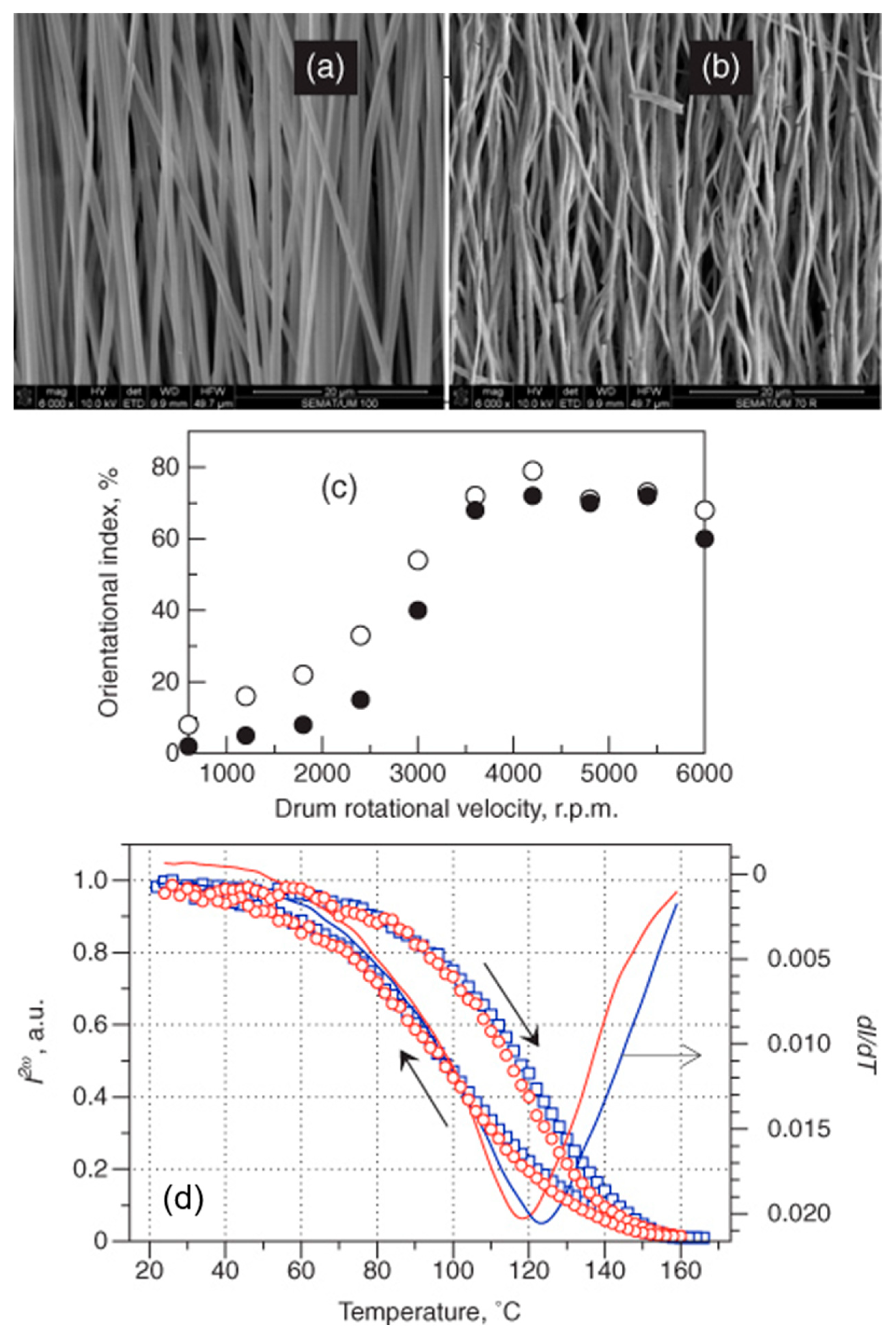
- Kongkhlang, T.; Tashiro, K.; Kotaki, M.; Chirachanchai, S. Electrospinning as a New Technique To Control the Crystal Morphology and Molecular Orientation of Polyoxymethylene Nanofibers. J. Am. Chem. Soc. 2008, 130, 15460–15466. [Google Scholar] [CrossRef]
- Isakov, D.; Gomes, E.D.; Belsley, M.S.; Almeida, B.; Cerca, N. Strong enhancement of second harmonic generation in 2-methyl-4-nitroaniline nanofibers. Nanoscale 2012, 4, 4978–4982. [Google Scholar] [CrossRef]
- Woodford, J.; Pauley, M.; Wang, C. Solvent dependence of the first molecular hyperpolarizability of p-nitroaniline revisited. J. Phys. Chem. A 1997, 101, 1989–1992. [Google Scholar] [CrossRef]
- Karna, S.P.; Prasad, P.N.; Dupuis, M. Nonlinear optical properties of p-nitroaniline: An ab initio time-dependent coupled perturbed Hartree–Fock study. J. Chem. Phys. 1991, 94, 1171–1181. [Google Scholar] [CrossRef]
- Champagne, B. Vibrational polarizability and hyperpolarizability of p-nitroaniline. Chem. Phys. Lett. 1996, 261, 57–65. [Google Scholar] [CrossRef]
- Trueblood, K.N.; Goldish, E.; Donohue, J. A three-dimensional refinement of the crystal structure of 4-nitroaniline. Acta Crystallogr. 1961, 14, 1009–1017. [Google Scholar] [CrossRef]
- Isakov, D.V.; Belsley, M.S.; de Matos Gomes, E.; Goncalves, H.; Schellenberg, P.; Almeida, B.G. Intense optical second harmonic generation from centrosymmetric nanocrystalline para-nitroaniline. Appl. Phys. Lett. 2014, 104, 181903. [Google Scholar] [CrossRef]
- Gonçalves, H.; Saavedra, I.; Ferreira, R.A.; Lopes, P.; de Matos Gomes, E.; Belsley, M. Efficient second harmonic generation by para-nitroaniline embedded in electrospun polymeric nanofibres. J. Phys. D Appl. Phys. 2018, 51, 105106. [Google Scholar] [CrossRef]
- Kolev, T.; Koleva, B.B.; Spiteller, M.; Mayer-Figge, H.; Sheldrick, W.S. 2-Amino-4-nitroaniline, a Known Compound with Unexpected Properties. J. Phys. Chem. A 2007, 111, 10084–10089. [Google Scholar] [CrossRef]
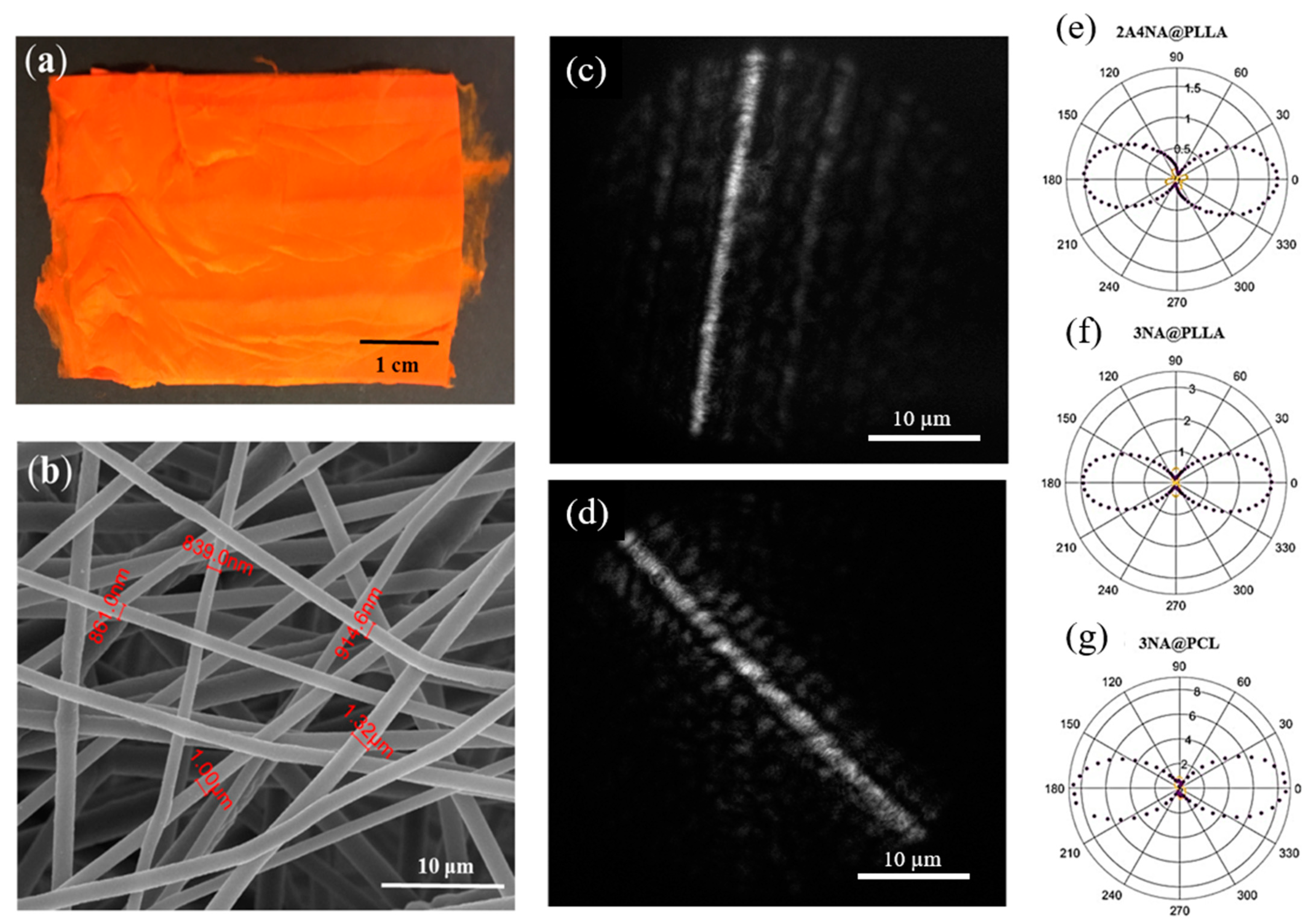
- Baptista, R.M.F.; Bernardo, C.R.; Belsley, M.S.; de Matos Gomes, E. Electrospun fibers with highly polarized second harmonic light from 2-amino-4-nitroaniline and 3-nitroaniline nanocrystals embedded in poly-L-lactic acid polymer. Opt. Mater. 2021, 116, 111089. [Google Scholar] [CrossRef]
- Liu, Y.; Pellerin, C. Stability and phase behavior of the poly(ethylene oxide)–urea complexes prepared by electrospinning. Polymer 2009, 50, 2601–2607. [Google Scholar] [CrossRef]
- Liu, Y.; Antaya, H.; Pellerin, C. Characterization of the stable and metastable poly(ethylene oxide)–urea complexes in electrospun fibers. J. Polym. Sci. Part B Polym. Phys. 2008, 46, 1903–1913. [Google Scholar] [CrossRef]
- Tadokoro, H.; Yoshihara, T.; Chatani, Y.; Murahashi, S. A preliminary report of structural studies on polyethylene oxide-urea complex. J. Polym. Sci. Part B Polym. Lett. 1964, 2, 363–368. [Google Scholar] [CrossRef]
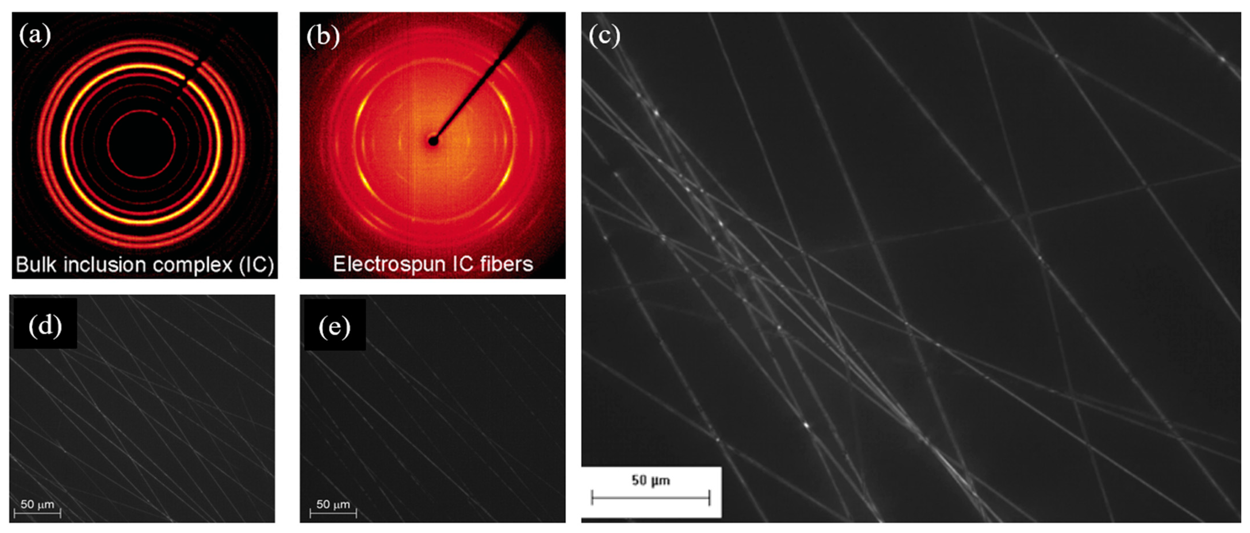
- Liu, Y.; Pellerin, C. Highly Oriented Electrospun Fibers of Self-Assembled Inclusion Complexes of Poly(ethylene oxide) and Urea. Macromolecules 2006, 39, 8886–8888. [Google Scholar] [CrossRef]
- Malara, A. Environmental concerns on the use of the electrospinning technique for the production of polymeric micro/nanofibers. Sci. Rep. 2024, 14, 8293. [Google Scholar] [CrossRef] [PubMed]
- Gagliardi, M. Global markets and technologies for nanofibers. PR Newswire 2016, 1, 1–10. [Google Scholar]
- Al-Abduljabbar, A.; Farooq, I. Electrospun Polymer Nanofibers: Processing, Properties, and Applications. Polymers 2023, 15, 65. [Google Scholar] [CrossRef]
- Sridhar, R.; Sundarrajan, S.; Venugopal, J.R.; Ravichandran, R.; Ramakrishna, S. Electrospun inorganic and polymer composite nanofibers for biomedical applications. J. Biomater. Sci. Polym. Ed. 2013, 24, 365–385. [Google Scholar] [CrossRef]
- Houis, S.; Engelhardt, E.; Wurm, F.; Gries, T. Application of polyvinylidene fluoride (PVDF) as a biomaterial in medical textiles. In Medical and Healthcare Textiles; Elsevier: Amsterdam, The Netherlands, 2010; pp. 342–352. [Google Scholar]
- Da Silva, D.; Kaduri, M.; Poley, M.; Adir, O.; Krinsky, N.; Shainsky-Roitman, J.; Schroeder, A. Biocompatibility, biodegradation and excretion of polylactic acid (PLA) in medical implants and theranostic systems. J. Chem. Eng. 2018, 340, 9–14. [Google Scholar] [CrossRef] [PubMed]
- Alfareed, T.M.; Slimani, Y.; Almessiere, M.A.; Nawaz, M.; Khan, F.A.; Baykal, A.; Al-Suhaimi, E.A. Biocompatibility and colorectal anti-cancer activity study of nanosized BaTiO3 coated spinel ferrites. Sci. Rep. 2022, 12, 14127. [Google Scholar] [CrossRef]
- Srinivasan, S.Y.; Paknikar, K.M.; Bodas, D.; Gajbhiye, V. Applications of cobalt ferrite nanoparticles in biomedical nanotechnology. Nanomedicine 2018, 13, 1221–1238. [Google Scholar] [CrossRef]
- Lickmichand, M.; Shaji, C.S.; Valarmathi, N.; Benjamin, A.S.; Kumar, R.A.; Nayak, S.; Saraswathy, R.; Sumathi, S.; Raj, N.A.N. In vitro biocompatibility and hyperthermia studies on synthesized cobalt ferrite nanoparticles encapsulated with polyethylene glycol for biomedical applications. Mater. Today Proc. 2019, 15, 252–261. [Google Scholar] [CrossRef]
- Xue, J.; Wu, T.; Dai, Y.; Xia, Y. Electrospinning and electrospun nanofibers: Methods, materials, and applications. Chem. Rev. 2019, 119, 5298–5415. [Google Scholar] [CrossRef] [PubMed]
- Inovenso. Nanospinner 416 Industrial Electrospinning/Spraying Line. Available online: https://www.inovenso.com/portfolio-view/nanospinner416/ (accessed on 25 February 2025).
- Elmarco. Available online: http://www.elmarco.com (accessed on 25 February 2025).
- O’Connor, D.; Hou, D. Manage the environmental risks of perovskites. One Earth 2021, 4, 1534–1537. [Google Scholar] [CrossRef]
- Ibn-Mohammed, T.; Koh, S.; Reaney, I.; Sinclair, D.; Mustapha, K.; Acquaye, A.; Wang, D. Are lead-free piezoelectrics more environmentally friendly? MRS Commun. 2017, 7, 1–7. [Google Scholar] [CrossRef]
- Bell, A.J.; Deubzer, O. Lead-free piezoelectrics-The environmental and regulatory issues. MRS Bull 2018, 43, 581–587. [Google Scholar] [CrossRef]
- Gomes, M.d.A.; Magalhães, L.G.; Paschoal, A.R.; Macedo, Z.S.; Lima, Á.S.; Eguiluz, K.I.B.; Salazar-Banda, G.R. An Eco-Friendly Method of BaTiO3 Nanoparticle Synthesis Using Coconut Water. J. Nanomater. 2018, 2018, 5167182. [Google Scholar] [CrossRef]


| Polymer | Inclusions | Heat Treatment | Purpose | Ref. |
|---|---|---|---|---|
| PVP Mw = 1,300,000 | KNbO3 | Heated to 550 °C at a 5 °C/min in air | For humidity sensors | [86] |
| PVP | (Na,K)NbO3 | Dried at 100 °C in nitrogen atmosphere for 12 h; annealed at 800 °C for 1 h in air | For biocompatible implants and tissue growth | [87] |
| PVP | PbZr1–xTixO3 (PZT) (52/48) | Annealed at 650 °C in air | To measure single-fiber bending piezoelectric voltage | [88] |
| PVP Mw = 13,000,000 | 0.96KNNS–0.04BNKZ, BZT–BCT, PZT (52/48) | Energy harvesting | [89] | |
| PVP Mw = 1,300,000 | BaTiO3 nanofibers in PDMS | Calcined at 1000 °C for 6 h, then inserted in PDMS | Flexible nanogenerators | [90] |
| PVP Mw = 1,300,000 | Aurivillius Bi5Ti3FeO15 | Dried in vacuum overnight at 90 °C; calcined at 300 °C for 2 h in oxygen burn PVP; annealed at 600 °C for 2 h in nitrogen; heating rate of 30 °C/h | Multiferroic nanofibers | [91] |
| PVP Mw = 1,300,000 | Co doped Ba0.7Sr0.3Ti0.95Co0.05O3 | Dried at 130 °C for 4 h and heated at 400 °C for 2 h; annealed at target temperatures (700 °C and 600 °C) for 2 h under a heating rate of 2 °C/min | Multiferroic nanofibers | [92] |
| PVP Mw = 1,300,000 | Na0.5Bi0.5TiO3 (NBT) nanofibers in PVDF | Dried at 60 °C for 48 h and then kept at 325 °C and 700 °C for 1 h; afterwards, NBT fibers inserted in PVDF | NBT–PVDF composites in capacitors for energy storage applications | [83] |
| xylene | Pb(Zr0.52Ti0.48)O3 (PZT) | The as-spun fibers and mats were isochronally sintered in air for two hours at 400, 500, 600, 700, and 800 °C. | To study PZT electrospun nanofiber synthesis | [93] |
| PVP | Co-doping of Nb5+–Nd3+ into PZT nanoneedles | Calcination at 800 °C for 2 h | For piezoelectric and high-dielectric-constant applications | [94] |
| PVP Mw = 1,300,000 | vertically aligned ultralong Pb(Zr0.52Ti0.48)O3 (PZT) nanowire | Calcination at 650 °C for 3 h | Wearable energy-harvesting and self-powered devices, flexible fiber nanogenerators | [95,96] |
| PVP Mw = 1,300,000 | BaTiO3 | Pyrolysis in nitrogen at 900 °C | Photocatalysis | [97] |
| PVP Mw = 1,300,000 | Ba0.6Sr0.4TiO3 (BST) | Different heat treatment temperatures: calcined at 600–800 °C for 2 h in air | To study BST synthesis | [98] |
| PVP Mw = 50,000 | Ba0.6Sr0.4TiO3 (BST) | Dried at 60 °C for 10 h; calcined at 900 °C in air, then included in PVDF to form BST–PVDF composites by drop casting | Nanocomposite capacitors | [99] |
| PVP | LiNbO3 (LNO) | Annealing at 700 °C for 6 h | To study LNO fiber synthesis | [100] |
| PVP | Mn-doped LiNbO3 | Annealing at 700 °C | To study Mn–LNO fiber synthesis | [101] |
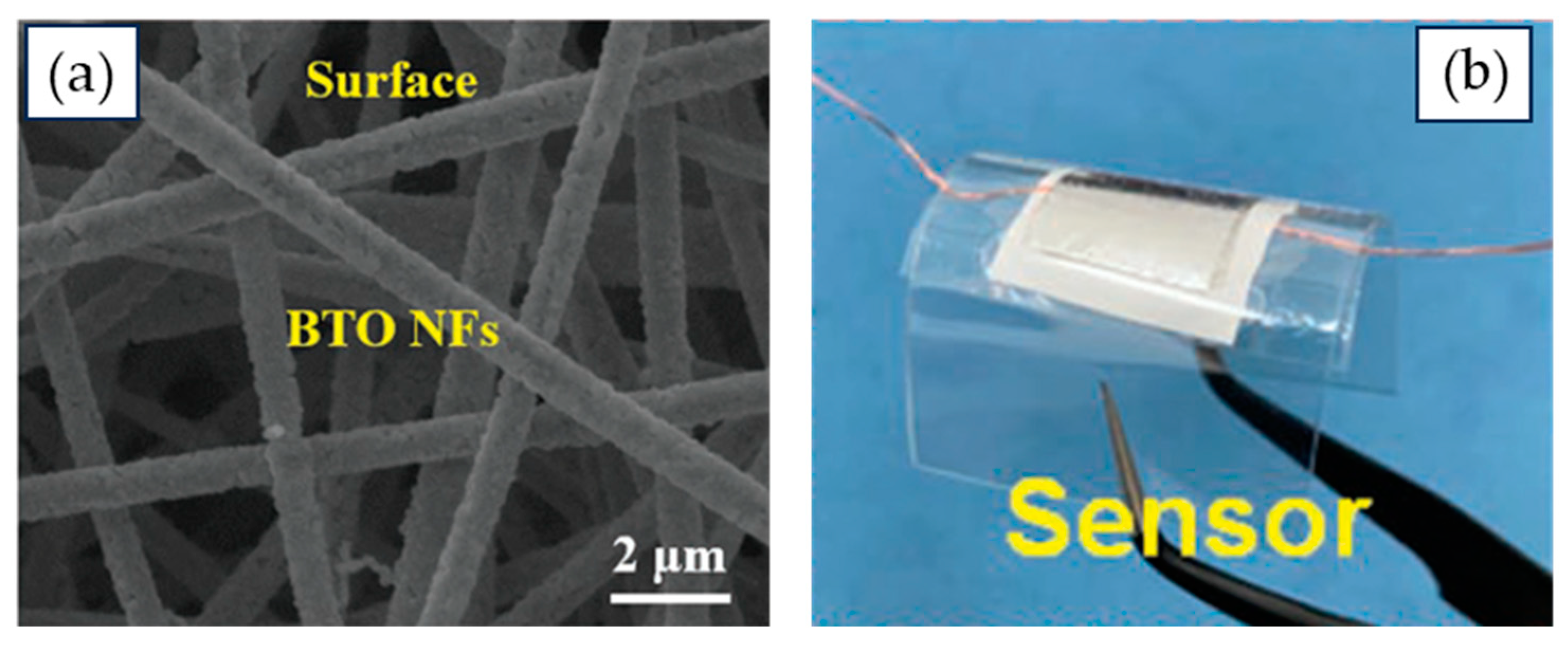
| PVP | BaTiO3-multiwalled carbon nanotube core–shell fibers | Put in vacuum oven at 70 °C for 1 h, and annealed at 800 °C in a nitrogen atmosphere for 2 h | Flexible piezoelectric pressure sensors | [102] |
| PAN Mw = 150,000 | BiFeO3 | Calcined at 500 °C for 3 h; then dispersed in PVDF to form a composite | Flexible piezoelectric nanogenerators | [103] |
| PVP Mw = 1,300,000 | BiFeO3 | Thermal annealing at temperatures from 400 to 600 °C for 2 h in ambient conditions | Photovoltaic devices | [104] |
| PVP Mw = 1,300,000 | BiFeO3 | Calcined at 520 °C for 2 h in an ambient atmosphere | Photocatalysis | [105] |
| Nylon-6 | BiFeO3 | Calcined at 600 °C for 2 h in air | Magnetoelectric α33 = 0.49 V cm–1 Oe−1 | [106] |
Disclaimer/Publisher’s Note: The statements, opinions and data contained in all publications are solely those of the individual author(s) and contributor(s) and not of MDPI and/or the editor(s). MDPI and/or the editor(s) disclaim responsibility for any injury to people or property resulting from any ideas, methods, instructions or products referred to in the content. |
© 2025 by the authors. Licensee MDPI, Basel, Switzerland. This article is an open access article distributed under the terms and conditions of the Creative Commons Attribution (CC BY) license (https://creativecommons.org/licenses/by/4.0/).
Share and Cite
Baptista, R.M.F.; de Matos Gomes, E.; Belsley, M.; Almeida, B. Ferroelectric and Non-Linear Optical Nanofibers by Electrospinning: From Inorganics to Molecular Crystals. Nanomaterials 2025, 15, 409. https://doi.org/10.3390/nano15050409
Baptista RMF, de Matos Gomes E, Belsley M, Almeida B. Ferroelectric and Non-Linear Optical Nanofibers by Electrospinning: From Inorganics to Molecular Crystals. Nanomaterials. 2025; 15(5):409. https://doi.org/10.3390/nano15050409
Chicago/Turabian StyleBaptista, Rosa M. F., Etelvina de Matos Gomes, Michael Belsley, and Bernardo Almeida. 2025. "Ferroelectric and Non-Linear Optical Nanofibers by Electrospinning: From Inorganics to Molecular Crystals" Nanomaterials 15, no. 5: 409. https://doi.org/10.3390/nano15050409
APA StyleBaptista, R. M. F., de Matos Gomes, E., Belsley, M., & Almeida, B. (2025). Ferroelectric and Non-Linear Optical Nanofibers by Electrospinning: From Inorganics to Molecular Crystals. Nanomaterials, 15(5), 409. https://doi.org/10.3390/nano15050409