Article

A Highly Efficient Visible Absorber Coating on a Curved Substrate

1
Key Laboratory of Optical System Advanced Manufacturing Technology, Changchun Institute of Optics, Fine Mechanics and Physics, Chinese Academy of Sciences, Changchun 130033, China
2
College of Da Heng, University of Chinese Academy of Sciences, Beijing 100049, China
3
Chang Chun Champion Optics Co., Ltd., Changchun 130000, China
*
Authors to whom correspondence should be addressed.
Coatings 2020, 10(1), 71; https://doi.org/10.3390/coatings10010071
Submission received: 13 December 2019 / Revised: 7 January 2020 / Accepted: 10 January 2020 / Published: 13 January 2020
(This article belongs to the Section Thin Films)

Abstract

:
In this study, we propose and fabricate a perfect absorber on a planar substrate using alternate silicon dioxide and ultrathin metallic lossy chromium (Cr) films. Furthermore, we transfer the absorber to a curved substrate via an optimization design of symmetric structures. The absorber exhibits a highly efficient absorption and large incident-angular tolerance characteristics in the whole visible region. We investigate each layer contribution to the absorption theoretically, and find that ultrathin (~5 nm) lossy Cr films play a dominant absorptive role. Using the effective interface method, we calculate the phase difference on the lossy Cr front surface. It is close to the destructive interference condition, from which we clarify why the proposed structures can produce a highly efficient absorption.

1. Introduction

Highly efficient light absorbers are greatly attractive in wide science and technology applications, such as stray light reduction, blackbody cavity, optical, and optoelectronic devices [1,2,3,4]. For example, improving the stray light suppression is greatly important for optical instruments, especially space-flight optical instruments. Earth and space astrophysical observations are tremendously impacted by stray light, which obscures very dim objects and degrades signal to noise in optical measurements. Stray light suppression using high-efficient absorbing surface can simplify instrument stray light controls and increase observational efficiencies [5,6]. Various approaches are utilized to produce a perfect absorber including plasmonic microstructures or metamaterials [7,8,9], inductively coupled plasma reactive ion etching (ICP-RIE) black silicon [10], and ultrathin lossy films [11,12,13]. Many studies have demonstrated that plasmonic microstructures and metamaterials can achieve a perfect or near-perfect absorption [14,15,16]. However, owing to their resonant nature, plasmonic absorbers are generally limited to a narrow spectral range. Therefore, combining several resonators together with the neighbor spectrum is an effective method to broaden the absorption spectrum [17]. For plasmonic microstructures and metamaterials, they often require time-consuming, complex, and expensive nano-scale fabrication processes.
Lithography-free ICP-RIE black silicon is a high-performance absorber in a broadband range from the visible to short-wavelength infrared region [10]. The absorber comprises a needle-like silicon nanostructure established by ICP-RIE on a highly doped silicon substrate. It can reach an absorptance higher than 99.5% in the broadband range. Recently, Liu et al. demonstrated an ultra-black absorber by SiAl film deposition and subsequent chemical etching [18]. They found that nanocone-like microstructures on the film surface could be fabricated easily by Al atom doping, leading to a significant decrease in the reflection of incident light. It also exhibits an average absorption higher than 99% from the visible to short-wavelength infrared region. Both approaches mentioned above are low-cost, but very effective to produce a large-area broadband ultra-black absorber.
Ultrathin lossy films provide an alternative approach to achieving a perfect absorber [11,12,13,19]. Usually, highly absorbing films are undesirable in anti-reflection or high-refection coating design because light propagation through such media destroys interference effects. However, under appropriate conditions, Capasso’s group have demonstrated that interference could instead persist in ultrathin, highly absorbing films with a few to tens nanometer thickness [12]. These coatings require minimal amounts of absorbing material that can be as thin as 5–20 nm for visible light, and have a low sensitivity to incident angle.
Up to now, all the demonstrated absorbers based on plasmonic microstructures or metamaterials, ICP-RIE black silicon, and ultrathin lossy films are done on a planar substrate. It is difficult to fabricate them on a curved substrate, particularly irregular ones. In this study, we propose and fabricate a perfect absorber on a planar substrate using ultrathin metallic lossy chromium (Cr) films. Furthermore, we transfer the absorber to a curved substrate via an optimization design of symmetric structures. The absorber on curved substrate exhibits a high absorption characteristic in the whole visible region. Detailed absorptive mechanisms are discussed.

2. Materials and Methods

The proposed broadband absorber is composed of alternate silicon oxide (SiO2) and metallic films, as depicted in Figure 1a. To achieve a highly efficient absorption characteristics in the structure, Cr with high index and extinction coefficient is adopted. The upper two thin Cr films mainly play an absorptive role, and the bottom Cr films with 200 nm thickness are assumed to be thick enough to block any light transmission. All layer thicknesses are optimized based on accurately characterizing optical constants of Cr and SiO2 films, and the absorption distributions and the light phase difference are analyzed by the transfer matrix method.
The alternate Cr/SiO2 films are deposited in an OPTRUN (OTFC-1300, OPTRUN, Kawagoe, Japan) coating machine, and the deposition method is ion beam-assisted electron beam evaporation. The thickness and deposition rate are controlled by using a quartz crystal oscillate monitor. The deposition rates are 1.5 Å/s for Cr and 6 Å/s for SiO2, respectively. Transmission electron microscopy (TEM) measurement is taken to clarify all layer morphology. The reflectance (R) and transmittance (T) spectra are measured in a Lambda-1050 spectrometer (PerkinElmer, Billerica, MA, USA), from which the absorptance (A) spectra are extracted through A = 1 − RT.

3. Results and Discussions

Figure 1b displays the optical image of fabricated absorber on K9 glass substrate with optimized film thickness. It looks perfectly black because the incident light in the visible region is completely absorbed. Figure 1c displays the absorber TEM image, where the bright layers are SiO2 films and the black layers are Cr films. The upper Cr layer shown in the high-resolution TEM image of Figure 1d is as thin as 5 nm, indicating that a highly accurate deposition is required.
Figure 2a,b show the theoretical absorption spectra of the designed absorber and the experimental absorption spectra of our fabricated absorber under different incident angle. As the bottom Cr layer with 200 nm thickness is thick enough to block any light transmission, the absorption spectra are extracted through A = 1 − R. The average theoretical and experimental absorption in the whole working region is up to 99.6% and 98.5% under normal incidence, respectively. With the incidence angle increasing, it still maintains a high-efficiency absorption (96.5%) even under a large incident angle of 45°. Thus, the absorber exhibits a large-angular tolerance feature on visible light absorption.
In order to clarify the absorption mechanism, we draw the optical admittance diagrams in Figure 3. As there is no transmitted light through the bottom thick Cr layer, the high absorptions correspond to the low reflections, which can be studied by the optical admittance. The admittance rotated trajectory is dependent on both the thickness and optical constant of deposited films. In Equation (1), we give the relationship between surface reflection and optical admittance [20]:
R = ( 1 ( x + i y ) 1 + ( x + i y ) ) 2
where x and y are the real and imaginary parts, respectively, of the admittance termination point. It is very clear from Equation (1) that minimizing the difference between the overall admittance (i.e., termination point of deposited films) and that of the air (1, 0) can suppress the surface reflection effectively. As shown in Figure 3, the starting admittance is simply 1.52, the admittance of K9 glass. It is found from admittance termination that the SiO2 layer plays an importantly antireflection role to reduce the surface reflection of the previous Cr layer. After each double Cr/SiO2 layers coating, the admittance terminates at the points of (0.31, −0.24), (0.71, −0.12), and (1.08, −0.03) for 550 nm light and (0.34, −0.50), (0.78, −0.21), and (1.09, −0.06) for 650 nm light, respectively, and gradually tends to 1. In another word, after six-layer film coating, the termination admittance is very close to air as the incident medium. This implies that the absorber composed of six-layer films shown in Figure 1 has a perfect anti-reflection surface and, therefore, it exhibits a very low surface reflection in the whole visible region.
In the following section, we will discuss how the visible light is absorbed greatly in the designed structures. To quantify the absorbed energy distributed into different layers of the absorber, we calculated it by using the simple equation [13]:
P = 1 2 c ε 0 α n | E ( x ) | 2
where c is the speed of light, ε0 is the permittivity of free space, n is the real part of the refractive index, α = 4πk/λ is the absorption coefficient with k being the imaginary part of the refractive index, and E(x) is the electric field amplitude. Figure 4 displays the absorbed energy distribution, from which it can be found that a dominate absorption occurs in the upper Cr layer. Its absorption peak is four times higher than that in the middle Cr layer. When incident lights penetrate the structure, about half of the energy is first dissipated within the upper Cr layer, although it has only 5 nm thickness. Then, the transmitted light is further dissipated within the middle Cr layer. Finally, the residual is absorbed within the bottom thick Cr layer. Although the bottom Cr layer has a very weak absorption, it plays a really important role in the absorption process. It can bounce back the remaining light and increase the absorption. If the bottom Cr layer is removed, partial incident light will transmit through the absorber structure directly and the theoretical absorption within the working wavelength range will decrease to 84.7% from 99.6%. Thus, the bottom Cr layer mainly works as a reflection mirror and contributes little to the direct absorption.
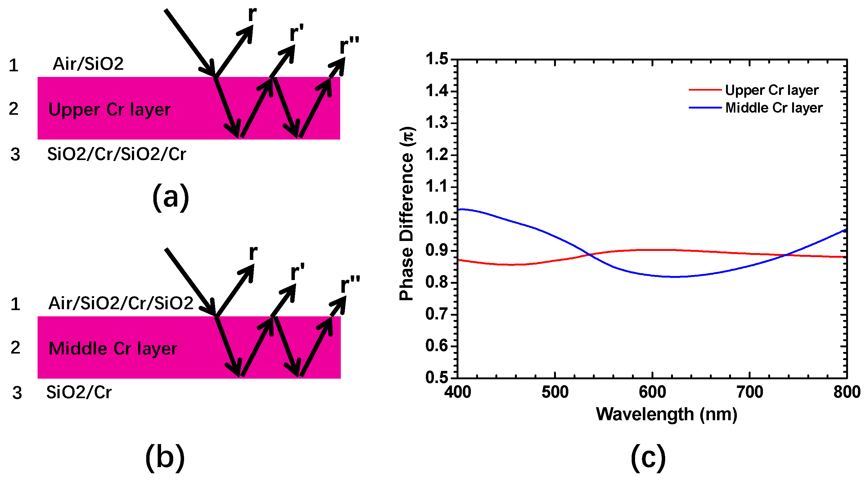
To further study the absorption in the thin Cr layer, we treat the six-layer structures in Figure 1 as a single Cr layer by effective interface method [21], as shown in Figure 5a,b, and calculate the reflection phase difference (Φ) between the decomposed partial wave r and other reflection components at the interface 1/2 (i.e., r′, r″, …) according to the following equation [12,22]:
r = r 12 + r 23 e 2 i β 2 1 + r 12 r 23 e 2 i β 2
where rpq = (mp − mq)/(mp + mq), β2 = (2π/λ)m2d2, and mp = np + ikp is the complex refractive index of layer p (np is the refractive index and kp is the extinction coefficient). As shown in Figure 5c, ϕ for both upper and middle Cr layers is close to the destructive interference condition (i.e., ϕ ≈ π) in the working wavelength range. The average Φ is 0.88π for the upper Cr layer and 0.90π for the middle Cr layer. Generally, the dielectric layer thickness should be λ/4n to meet the π phase difference, which is the mechanism of the conventional Gires–Tournois etalon [23,24]. However, for the lossy films, an additional phase difference can be introduced by its complex refractive index, which is the key issue to tune the phase difference to meet destructive interference even under its thickness <<λ/4n [12].
The above-mentioned absorber can be fabricated only on a planar or smooth curved substrate. It becomes extremely difficult to be done on a curved substrate owing to serious oblique-angle deposition influence [25]. In order to extend its application on a curved substrate, we optimized the absorber structure and its fabrication process. Figure 6a displays the optimized absorber with a total thickness of 700 nm composed of double symmetric structures in Figure 1a. The double symmetric structures lead to both upper and bottom surfaces having a perfect anti-reflection effect, as shown in Figure 6b. It has a greatly beneficial effect on its fabrication on a curved substrate, which will be interpreted in the following. Meanwhile, in Figure 1, the absorber bottom surface has a high reflection around 50%.
Figure 7a displays how the absorber is fabricated on a curved substrate. First, thin positive photoresist films are prepared on a planar substrate through a spin coating method, and subsequently, the double symmetric structures are deposited on photoresist films. Second, the sample is dipped into acetone solutions to strip out the absorber from the substrate. Third, the absorber is grinded into small pieces, mixed with transparent glue water by a ratio of around 1:5, and finally coated on a curved substrate. Figure 7b displays a curved substrate image before and after absorber coating taken under 45° incidence. The curved substrate has a hemisphere surface with a diameter of 30 mm. It looks greatly black even under a large angle observation. Its integrated absorption spectra are given in Figure 7c. The average integrated absorption is as high as 97.5% in the whole visible region. The perfect absorption mainly originates from two factors. One is that it has a large-angular tolerance feature, shown in Figure 2. Another is that double sides of the design structures shown in Figure 6a are super black. No matter which side is up when small pieces are coated on substrate, highly efficient absorption can be achieved. The proposed absorber is grinded into small pieces and mixed with transparent glue water; it is like viscous liquid. Thus, in general, it can be applied on both any small radius and any irregular-shape structure. It has great potential application on stray light suppression for complex components in optical instruments, especially space-flight optical instruments. It can simplify instrument stray light controls and increase observational efficiencies.

4. Conclusions

In summary, we have demonstrated a broadband absorber working in the visible light range using alternate SiO2 and lossy Cr films. Furthermore, we transfer the absorber to a curved substrate via an optimization design of symmetric structures. The absorber fabricated on a planar substrate exhibits a highly efficient absorption from 400 to 800 nm, and a large incident-angular tolerance characteristic. By theoretical analysis, we found that the upper ultrathin Cr layer played a dominant absorptive role. After that, the transmitted light was further absorbed within the middle Cr layer. Using the effective interface method, we calculated the phase difference on the front surface of lossy Cr films, and we found that the phase differences were close to the destructive interference condition, leading to a highly efficient absorption within the proposed structures.

Author Contributions

Conceptualization, R.G., H.Y., and H.B.; Methodology, R.G., H.L., and Z.L. (Zhen Liu); Validation, R.G., Z.L. (Zizheng Li), and F.Y.; Formal Analysis, R.G., Y.W., and H.Y.; Investigation, H.Y., H.B., and X.W.; Data Curation, R.G., Q.L., and X.W.; Writing—Original Draft Preparation, R.G., Q.L., and Z.S.; Writing—Review and Editing, R.G., H.Y., and H.B. All authors have read and agreed to the published version of the manuscript.

Funding

This research was funded by the National Natural Science Foundation of China (Grant Nos. 61675199, 61227901, 61875193, 61905238, and 61705226), the Jilin Province Science Foundation of China (Grant No. 20190201126JC), and the Changchun Science and Technology Innovation “Shuangshi Project” Major Scientific and Technological Project (Grant No. 19SS004).

Acknowledgments

In this section you can acknowledge any support given which is not covered by the author contribution or funding sections. This may include administrative and technical support, or donations in kind (e.g., materials used for experiments).

Conflicts of Interest

The authors declare no conflict of interest.

References

  1. Theocharous, E.; Chunnilall, C.J.; Mole, R.; Gibbs, D.; Fox, N.; Shang, N.; Howlett, G.; Jensen, B.; Taylor, R.; Reveles, R.J.; et al. The partial space qualification of a vertically aligned carbon nanotube coating on aluminium substrates for EO applications. Opt. Express 2014, 22, 7290–7307. [Google Scholar] [CrossRef] [PubMed]
  2. Yang, J.; Luo, F.; Kao, T.S.; Li, X.; Ho, W.G.; Teng, J.; Luo, X.; Hong, M. Design and fabrication of broadband ultralow reflectivity black Si surfaces by laser micro/nanoprocessing. Light Sci. Appl. 2014, 3, e185. [Google Scholar] [CrossRef]
  3. Liu, X.; Gao, J.; Yang, L.; Wang, X.; Wang, T.; Shen, Z.; Liu, Z.; Liu, H.; Zhang, J.; Li, Z.; et al. Microcavity electrodynamics of hybrid surface plasmon polariton modes in highquality multilayer trench gratings. Light Sci. Appl. 2018, 3, 14. [Google Scholar]
  4. Liu, Y.; Hong, M. Ultralow broadband optical reflection of silicon nanostructured surfaces coupled with antireflection coating. J. Mater. Sci. 2012, 47, 1594–1597. [Google Scholar] [CrossRef]
  5. Hagopian, J.G.; Getty, S.A.; Quijada, M.; Tveekrem, J.; Shiri, R.; Roman, P.; Butler, J.; Georgiev, G.; Livas, J.; Hunt, C.; et al. Multiwalled carbon nanotubes for stray light suppression in space flight instruments. In Proceedings of the International Society for Optics and Photonics, San Diego, CA, USA, 1–5 August 2010; Volume 7761, p. 77610F. [Google Scholar]
  6. Chunnilall, C.J.; Lehman, J.H.; Theocharous, E.; Sanders, A. Infrared hemispherical reflectance of carbon nanotube mats and arrays in the 5–50 um wavelength region. Carbon 2012, 50, 5348–5350. [Google Scholar] [CrossRef]
  7. Ji, D.; Song, H.; Zeng, X.; Hu, H.; Liu, K.; Zhang, N.; Gan, Q. Broadband absorption engineering of hyperbolic metafilm patterns. Sci. Rep. 2014, 4, 4498. [Google Scholar] [CrossRef] [Green Version]
  8. Hedayati, M.K.; Javaherirahim, M.; Mozooni, B.; Abdekaziz, R.; Tavassolizadeh, A.; Chakravadhanula, K.S.V.; Zaporojtchenko, V.; Strunkus, T.; Faupel, F.; Elbahri, M. Design of a perfect black absorber at visible frequencies using plasmonic metamaterials. Adv. Mater. 2011, 23, 5410–5414. [Google Scholar] [CrossRef] [Green Version]
  9. Bora, M.; Behymer, E.M.; Dehlinger, D.A.; Britten, A.J.; Larson, C.C.; Chang, A.S.P.; Munechika, K.; Nguyen, T.H.; Bond, C.T. Plasmonic black metals in resonant nanocavities. Appl. Phys. Lett. 2013, 102, 251105. [Google Scholar] [CrossRef]
  10. Steglich, M.; Lehr, D.; Ratzsch, S.; Kasebier, K.; Schrempel, F.; Kley, E.; Tunnermann, A. An ultra-black silicon absorber. Laser Photonics Rev. 2014, 8, L13–L17. [Google Scholar] [CrossRef]
  11. Ding, F.; Mo, L.; Zhu, J.; He, S. Lithography-free, broadband, omnidirectional, and polarization-insensitive thin optical absorber. Appl. Phys. Lett. 2015, 106, 061108. [Google Scholar] [CrossRef]
  12. Kats, M.A.; Blanchard, R.; Genevet, P.; Capasso, F. Nanometre optical coatings based on strong interference effects in highly absorbing media. Nat. Mater. 2013, 12, 20. [Google Scholar] [CrossRef] [PubMed]
  13. Lee, K.T.; Ji, C.; Guo, L.J. Wide-angle, polarization-independent ultrathin broadband visible absorbers. Appl. Phys. Lett. 2016, 108, 031107. [Google Scholar] [CrossRef]
  14. Liu, N.; Mesch, M.; Weiss, T.; Hentschel, M.; Giessen, H. Infrared perfect absorber and its application as plasmonic sensor. Nano Lett. 2010, 10, 2342–2348. [Google Scholar] [CrossRef] [PubMed]
  15. Liu, X.; Starr, T.; Starr, A.F.; Padilla, W.J. Infrared spatial and frequency selective metamaterial with near-unity absorbance. Phys. Rev. Lett. 2010, 104, 207403. [Google Scholar] [CrossRef] [PubMed] [Green Version]
  16. Li, Q.; Gao, J.; Yang, H.; Liu, H. A super meta-cone absorber for near-infrared wavelengths. Plasmonics 2016, 11, 1067–1072. [Google Scholar] [CrossRef]
  17. Cui, Y.; Xu, J.; Hung, F.K.; Jin, Y.; Kumar, A.; He, S.; Fang, N.X. A thin film broadband absorber based on multi-sized nanoantennas. Appl. Phys. Lett. 2011, 99, 253101. [Google Scholar] [CrossRef]
  18. Liu, Z.; Liu, H.; Wang, X.; Yang, H.; Gao, J. Large area and broadband ultra-black absorber using microstructured aluminum doped silicon films. Sci. Rep. 2017, 7, 42750. [Google Scholar] [CrossRef] [Green Version]
  19. Song, H.; Guo, L.; Liu, Z.; Liu, K.; Zeng, X.; Ji, D.; Zhang, N.; Hu, H.; Jiang, S.; Gan, Q. Nanocavity enhancement for ultra-thin film optical absorber. Adv. Mater. 2014, 26, 2737–2743. [Google Scholar] [CrossRef]
  20. Macleod, H.A. Thin-Film Optical Filters, 4th ed.; CRC Press: Boca Raton, FL, USA; Taylor & Francis Group: London, UK; New York, NY, USA, 2010. [Google Scholar]
  21. Smith, S.D. Design of multilayer filters by considering two effective interfaces. J. Opt. Soc. Am. A 1958, 48, 43–50. [Google Scholar] [CrossRef]
  22. Liu, D.; Yu, H.; Yang, Z.; Duan, Y. Ultrathin planar broadband absorber through effective medium design. Nano Res. 2016, 9, 2354–2363. [Google Scholar] [CrossRef]
  23. Gires, F.; Tournois, P. Interferometre utilisable pour la compression d’impulsions lumineuses modulees en frequence. Comptes Rendus de l’Académie des Sciences Série I. Mathématique 1964, 258, 6112–6615. [Google Scholar]
  24. Born, M.; Wolf, E. Principles of Optics, 6th ed.; Pergamon Press Ltd.: London, UK, 1980. [Google Scholar]
  25. Karabacak, T. Thin-film growth dynamics with shadowing and re-emission effects. J. Nanophotonics 2011, 5, 052501. [Google Scholar] [CrossRef] [Green Version]
Figure 1. (a) The proposed absorber structure diagram; (b) a photograph of the fabricated absorber under 45° incidence; (c) the transmission electron microscopy (TEM) image of the absorber structures; (d) high-resolution TEM image.
Coatings 10 00071 g001
Figure 2. (a) The calculated absorption spectra of the designed absorber under different incident angle; (b) the measured absorption spectra of our fabricated absorber under different incident angles.
Coatings 10 00071 g002
Figure 3. (a) The optical admittance diagram at 550 nm incident light; (b) the optical admittance diagrams at 650 nm incident light.
Coatings 10 00071 g003
Figure 4. (a) The absorbed energy distribution within the absorber structures at 550 nm incident light; (b) the absorbed energy distribution within the absorber structures at 650 nm incident light.
Coatings 10 00071 g004
Figure 5. (a) Effective upper Cr layer diagram for six-layer structures; (b) effective middle Cr layer diagram for six-layer structures; (c) the calculated reflection phase difference on the front surface of both upper and middle Cr layers.
Coatings 10 00071 g005
Figure 6. (a) The optimized absorber diagram with double symmetric structures; (b) both upper and bottom surface image of the optimized absorber.
Coatings 10 00071 g006
Figure 7. (a) The processes of the absorber fabricated on a curved substrate; (b) a hemisphere substrate image before and after absorber coating taken under 45° incidence; (c) the integrated absorption spectra.
Coatings 10 00071 g007