Abstract
Type 45 steel substrate surfaces were coated with Ni–Co–P alloy coatings using jet electrodeposition in varying reciprocating sweep speed and jet gap to improve the wear and seawater polarization resistance of the substrate surface. The properties of the deposited coatings were analyzed and characterized. The results showed that the morphologies of the cross-section, thickness, and chemical composition of coatings were affected by reciprocating sweep speed and jet gap variation. At a reciprocating sweep speed of 175 mm·s−1 coupled with a jet gap of 2.0 mm, the content of Co element in the deposit attained the highest value of 47.66 wt.%. Reciprocating sweep speed and jet gap variation exhibited no significant influence on either the phase structure or the peak intensities of deposited Ni–Co–P coatings, but an obvious preferred orientation was evident in the (111) plane. Further increase in reciprocating sweep speed and jet gap caused an initial increase in the microhardness of Ni–Co–P alloy coatings followed by a decrease, where the highest value attained was 635 HV0.1. At a jet gap of 2.0 mm and a reciprocating sweep speed of 175 mm·s−1, Ni–Co–P alloy coatings reached a minimum wear scar width value of 460 µm. Electrochemical tests showed that the seawater corrosion resistance of coatings exhibited an observable change with increased reciprocating sweep speed and jet gap. The Ni–Co–P alloy coatings exhibited the highest polarization resistance (Rp) of 28.32 kΩ·cm−2 when the reciprocating sweep speed was 175 mm·s−1 and the jet gap was 2.0 mm, which indicated that the coatings had better seawater corrosion resistance.
1. Introduction
Materials form a key pillar in industrial engineering technology. Generally, the mechanical, thermal, and electrochemical interactions are initiated on the surface of the coatings. As such, there is a constant threat of wear and corrosion phenomena that seriously degrade the properties of equipment leading to reduced production capacity and increased maintenance costs. It is therefore critical to develop mitigation measures against these phenomena. Over the years, various forms of surface enhancement techniques have been employed to mitigate the negative effects of wear and corrosion on the surfaces of metallic coatings. Such techniques include: powder metallurgy, thermospraying, and electrodeposition. These techniques have allowed the synthesis of entirely new engineering materials that exhibit superior properties.
Electrodeposition is a surface modification technique that relies on an electrochemical approach to coat the surfaces of metals with other materials. Electrodeposition has several advantages over the other techniques, and these include: simplicity, possibility of coating parts with different geometries, affordability, and reproducibility. Different metals have been used to coat other metals depending on desired properties. Ni is one such metal. Ni coatings have been used for surface protection, functional uses, and decoration purposes [1,2]. Other metals have been deposited together with Ni to form alloy coatings which exhibit enhanced mechanical properties. These range from Co, P, W [3], to Mo and when either of them is combined with Ni, they form binary alloy coatings. This makes it possible to tailor the coatings depending on the properties desired. Nickel-based coatings have been reported to exhibit superior hardness, wear resistance, and excellent corrosion resistance, and are therefore employed in the marine industry, power generation industry, chemical, and automotive industries [4]. In some instances, the properties of deposited coatings can be further improved by depositing Ni with two other metals to form ternary alloy coatings. These coatings include Ni-Zn-P, Ni-Cu-P, Ni-Mo-P, and Ni-Co-P. Zhao et al. [5] compared a Ni–P alloy coating with a Ni–Zn–P alloy coating in artificially simulated seawater and found that the deposited Ni–Zn–P alloy exhibited a more uniform and smooth coating compared to the Ni–P coating and the corrosion rate of the Ni–Zn–P alloy coating was significantly lower than that of the Ni–P coating. Fang et al. [6] studied the electrochemical activity of Ni–P and Ni–Cu–P alloy coatings in varying artificial seawater temperatures. It was concluded that the corrosion current densities of amorphous Ni–P and Ni–Cu–P coatings and nanometer crystalline Ni–Cu–P coatings increased with an increase in artificial seawater temperature. Wang et al. [7] reported that inclusion of Sn2+ in the Ni–P bath provided better corrosion resistance in artificial seawater. These research works demonstrate that ternary alloy coatings have better seawater corrosion resistance compared to binary alloy coatings in the marine environment.
Ni–Co–P alloy coatings are often used as electrocatalysis materials, anticorrosion materials, and diffusion barrier owing to their exceptional wear resistance and hardness, excellent saturation magnetization, polarization resistance, and low coercive force [8]. Fetohi et al. [9] compared Ni–P alloy coatings with Ni–Co–P alloy coatings and found that Ni–Co–P alloy coatings had lower corrosion current densities and therefore exhibited better corrosion resistance. Khan et al. [10] reported on the influence of electrodeposition parameters on Co–P binary alloy coatings and Ni–Co–P tertiary alloy coatings. From the analysis, it was found that the coercivity for deposited Ni–Co–P alloy coatings was higher than that of Co–P alloy coatings. Lew et al. [11] reported that nickel content was low and cobalt content was high at low current density and at high electrolyte pH. When the current density was decreased and the electrolyte pH increased, the amorphous phase of Ni–Co–P coatings increased while the face-centered cubic (FCC) phase intensity decreased. Hence, studies on Ni–Co–P alloy coatings are crucial for practical, industrial, and academic applications. Additionally, studies on seawater polarization resistance of Ni–Co–P alloy coatings have important significance as well as value in the improvement of metals surface properties.
Over the past few decades, interest in jet electrodeposition has been continuously growing due to high efficiency, high limiting current density, low processing costs, and high selectivity compared to conventional electrodeposition methods [12,13,14,15,16]. Moreover, jet electrodeposition is also used to enhance local surface of metallic parts [17]. Tang et al. [18] investigated the influence of bath flow on jet electrodeposited Co–Ni alloy coating properties. The grains of Co–Ni alloy coating became smaller and there was an increase in mass fraction of Co with increasing bath flow. Wang et al. [19] studied the influence of current density, particle concentration in the electrolyte, flow of solutions and spray gun speed on the content of particles deposited in the coating and Co–Cr3C2 coating properties. The optimal parameters for preparing the composite coating were determined and it was found that the gun movement speed had the most significant influence on the mass fraction of Cr3C2 in the coating. Zhang et al. [20] reported that the Co–Ni–Cr3C2 composite coating deposited using jet electrodeposition exhibited the highest deposition, best wear resistance and microhardness at a current density of 40 A/dm2. Qiao et al. [14] investigated the influence of temperature, cathodic current density and jet speed on Co2+ ion content in Ni–Co coatings with jet electrodeposition. It was found that a single-phase face-centered cubic (FCC) structure was exhibited by Ni–Co alloy coatings at low Co content. Cui et al. [21] concluded that the flow rate of the plating solution increased with an increase in the diameter of the nickel anode nozzle. Jiang et al. [22] reported that pure nickel coatings were no longer characterized by distinct cell bulges and microcracks when magnetic field enhanced jet electrodeposition was used. Ning et al. [23] recovered Cu2+ from wastewater using jet electrodeposition. A Faradaic efficiency of 77.2% was achieved and the Cu2+ removed from wastewater was in excess of 97.4%. Kim et al. [24] proposed using jet-circulating electrodeposition for a novel selective Cu pattern metallization process. However, the distance between suction nozzle and electrode nozzle in jet circulating electrodeposition was not considered.
The results collected from above experiments indicated that jet electrodeposition method has some unique favorable aspects in the synthesis of the coatings compared with conventional electrodeposition. The grains, phase, deposition, wear resistance and microhardness of coatings exhibited an observable change with jet electrodeposition parameter. Additionally, the mechanical properties of the coating are significantly improved by jet electrodeposition method under suitable process parameters. Qiao et al. [25] concluded that the Ni–Co alloys synthesized by jet electrodeposition were characterized by lower grain sizes coupled with improved microhardness. To further enhance these properties and increase coercivity, Phosphorus has been added to the Ni–Co alloy [10]. Substantial research on corrosion and wear resistance of Ni–Co–P alloy coatings has also been undertaken [26,27]. The properties of jet electrodeposited Ni-Co-P coatings with varying reciprocating sweep speeds and jet gaps have yet to be broadly studied over the years. Usually, constant reciprocating sweep speed [28] and jet gap [29] are selected for the jet deposition technique. For this reason, the study of Ni–Co–P alloy coatings deposited with jet electrodeposition while taking into consideration varying reciprocating sweep speeds and jet gaps is an important research area for improvement of metallic material surface wear resistance and seawater corrosion resistance properties.
In this research, 45 steel substrates were coated with Ni–Co–P alloy coatings using jet electrodeposition with varying reciprocating sweep speeds and jet gaps so as to enhance the seawater polarization resistance and wear resistance of metals. The cross-section morphology, chemical composition, and coating’s crystalline structure were investigated and characterized using scanning electron microscopy (SEM), energy dispersive spectroscopy (EDS), and X-ray diffraction (XRD), respectively. Meanwhile, the wear resistance, microhardness, and seawater corrosion resistance of the coatings were analyzed and characterized using a friction wear tester, microhardness tester, and electrochemical workstation, respectively. The experiments conducted coupled with results analyzed can prove advantageous for improving seawater polarization resistance and wear resistance of Ni–Co–P alloy coatings as well as providing a theoretical framework for application of the coatings.
2. Experimental
2.1. Experimental Setup
The jet electrodeposition technique has several advantages such as high deposition current density and high velocity, which are used for synthesis or large-scale production of nanocrystalline materials; it shows broad applications and is worthy of development. The self-made jet electrodeposition equipment was employed to fabricate the Ni–Co–P coatings in this study. Figure 1 shows the experimental setup of the numerically controlled jet electrodeposition. It can be seen that the experimental setup comprises of a power source, machine accessories, a numerical control servo device, circulating pump, and a thermostatic apparatus. The anodic nozzle oscillates along the Y-axis in a continuous motion as the plating solution passes through it. The experimental device can vary reciprocating sweep speed, jet gap, jet voltage, and also control the temperature and flow of plating solution. The power source was utilized to control the voltage and current. The servo device was used to control the reciprocating sweep speed and regulate the jet gap during the jet electrodeposition process. The plating solution could be jetted from the anode cavity to the 45-steel substrate surface through the circulating pump. At the same time, metal cations of the plating solution could achieve jet electrodeposition under the action of an electric field.
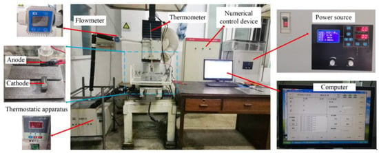
Figure 1.
Numerically controlled jet electrodeposition experimental setup.
2.2. Materials and Pretreatment
The substrate materials were 45 steel bars of dimensions 30 mm × 8 mm × 7 mm procured from Suzhou Co. (Jiangsu, China). The chemical compositions of the 45 steel substrates were as follows: 0.59 wt.% Mn, 0.46 wt.% C, 0.27 wt.% Si, 0.05 wt.% Cu, 0.05 wt.% Cr, 0.04 wt.% Ni, 0.02 wt.% S, and 0.02 wt.% P, and the rest was Fe. To ensure a favorable quality deposit was obtained, the 45 steel substrates were taken through a series of pretreatment processes prior to deposition. Firstly, #320 mesh tungsten carbide (WC) sandpaper was used to clean and polish the 45 steels substrate’s surface. In order to obtain a bright and smooth surface, further abrasive action with #800 to #1500 grade WC sandpaper was conducted. Secondly, the 45 steel samples were degreased using an electric cleaning solution. Thirdly, the 45 steel samples were connected to the positive electrode and immersed in a strong activation solution for the removal of the oxide film. Finally, the 45 steel samples were treated in a weak activation solution so as to remove carbon black. Deionized water was used to rinse the samples after each step. The composition of the pretreatment solutions and operating conditions are given in Table 1.

Table 1.
Pretreatment solutions composition and operating conditions.
2.3. Synthesis of Ni–Co–P Alloy Coatings
Self-made jet electrodeposition equipment was used to synthesize Ni–Co–P alloy coatings on 45 steel samples with (i) varying reciprocating sweep speeds (100, 125, 150, 175, 200, 225, 250 and 275 mm·s−1) at a constant jet gap of 2.0 mm, and (ii) varying jet gaps between the nozzle and the cathode (1.5, 1.75, 2.0, 2.25, 2.5, 2.75, 3.0 and 3.25 mm) at a constant reciprocating sweep speed of 175 mm·s−1. The coatings were deposited from an aqueous solution containing 200.0 g·L−1 Nickel sulphate (NiSO4·6H2O), 60.0 g·L−1 Citric acid monohydrate (C6H8O7·H2O), 30.0 g·L−1 Nickel chloride hexahydrate (NiCl2·6H2O), 30.0 g·L−1 Boric acid (H3BO3), 20.0 g·L−1 Cobaltous sulphate heptahydrate (CoSO4·7H2O), 20.0 g·L−1 Phosphorous acid (H3PO3), 0.080 g·L−1 Sodium dodecyl sulfate (CH3(CH2)11SO4Na) and 0.020 g·L−1 Sulfourea (H2NCSNH2). All the jet electrodeposition experiments were performed at a temperature of 60 °C, an injection speed of 1.5 m·s−1, a jet voltage of 12 V and a electrodeposition time of 20 min. These parameters were selected after consideration of past research on similar coatings where the temperature and jet voltages had been optimized [30].
2.4. Sample Characterization
The cross-section morphologies and predominant element contents in the deposited coatings were observed and analyzed by a scanning electron microscope (SEM, Quanta 250, FEI, Hillsboro, OR, USA) and an energy dispersive spectrometer (EDS, XFlash Detector 5030, BRUKER, Karlsruhe, Germany), respectively. X-ray diffraction (XRD, X’Pert Powder, PANalytical B.V., Almelo, The Netherlands) was used to determine the phase composition of coatings. The monochromatic CuKα radiation was scanned with a voltage of 40 kV. Diffraction patterns were recorded in the 2θ range from 20° to 90° at a scanning rate of 4°/min.
A microhardness tester (Struers, Duramin-40 A1, Ballerup, Copenhagen, Denmark) was used to measure the microhardness of various samples. A test load of 100 g coupled with an indentation time of 15 s was selected. Five randomly selected locations were tested on each sample, and four samples were selected for each batch of the experiment. The total values were then summed up and an average value was computed and taken to be the microhardness value. A high frequency reciprocating wear test machine was used to measure the wear resistance of various coatings. The friction pair consisted of GCr15 bearing steel ball having a diameter of 3 mm. The applied test load was 3.2 N, the time was 30 min, and the speed of main shaft was 500 r/min. An ultrasonic cleaner was used to clean the samples before and after each test. The surface morphologies of the wear grooves were determined using a scanning electron microscope (SEM) and laser scanning confocal microscopy (LSCM, OLS4000, OLYMPUS, Tokyo, Japan).
An electrochemical workstation (CS350, Wuhan Corrtest Instruments Corp., Ltd., Wuhan, China) was used to investigate the corrosion potentiodynamic polarization curves, Nyquist and Bode plots of various samples. All the samples used as working electrode (WE) had an exposed surface area of 1 cm2. The counter electrode (CE) and reference electrode (RE) consisted of a platinum plate and saturated calomel electrode, respectively. The tests were performed in an artificial seawater environment at room temperature. Standard ASTM D 1141–98 [30] was taken into consideration when preparing the chemical composition of the corrosive medium. Prior to the electrochemical experiments, the samples were immersed in the corrosive artificial seawater for approximately 0.5 h to attain open circuit potential (Eocp). The corrosion potentials (Ecorr) and corrosion current densities (Icorr) were determined using Tafel method. The sweeping range was selected as −0.6 V to +0.6 V with respect to the Eocp and the sweeping rate was 0.5 mV/s. The corrosion rate was obtained from the extrapolated data using CView software (CView4.4, CorrTest, NC, USA). The electrochemical impedance spectroscopy (EIS) test was recorded in the frequency range of 105 Hz to 10−2 Hz and a sinusoidal excitation amplitude of 10 mV root mean square.
3. Results and Discussion
3.1. Effects of Varying Reciprocating Sweep Speed and Jet Gap on Ni–Co–P Alloy Coating’s Cross-Section Morphologies
The influence of varying the reciprocating sweep speed on cross-section morphologies of coatings is displayed in Figure 2 (constant jet gap of 2.0 mm). It is evident from Figure 2 that there was a clear change in Ni–Co–P alloy coatings’ cross-section morphologies with increased reciprocating sweep speeds. From Figure 2 it can be seen that the average thickness of the coating was 20.5 µm when the reciprocating sweep speed was 100 mm·s−1. It is evident that the average thickness of the coating increased with the increase in reciprocating sweep speed reaching a value of 37.5 µm at 275 mm·s−1. The above phenomena may be associated with the fact that increasing reciprocating sweep speed leads to an increase in the stirring strength of the plating solution, thereby decreasing the diffusion layer thickness, which in turn increased the limiting current density and increased the deposition speed [31].
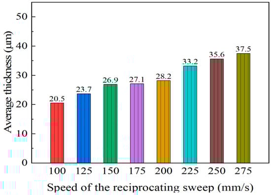
Figure 2.
Effect of varying reciprocating sweep speed on average coating thicknesses.
Figure 3 represents the Ni–Co–P coating deposited at 100 and 275 mm·s−1. From the figures, it is evident that the coating was uniform and defect free.
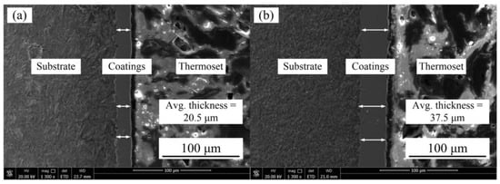
Figure 3.
SEM images of Ni–Co–P coatings deposited with reciprocating sweep speed: (a) 100 mm·s−1 and (b) 275 mm·s−1.
The effect of varying the jet gap on cross-section morphologies of coatings is displayed in Figure 4 with a constant reciprocating sweep speed of 175 mm·s−1. It is evident from Figure 4 that the Ni–Co–P alloy coatings’ cross-section morphologies exhibited an observable change with increased jet gap. From Figure 4, it is evident that the average thickness of coatings was 34.8 µm when the jet gap was 1.5 mm. It is clear that the average thickness of coatings decreased with the increase in jet gap reaching a value of 15.5 µm at 3.25 mm. The above phenomena may be associated with decrease in the pressure and flow velocity of the plating solution sprayed by the nozzle as the jet gap increased. The degree of turbulence of the plating solution on the coating surface was weakened and the thickness of the diffusion layer increased, and this in turn decreased the current density between the nozzle and the cathode. As reported previously by Wang et al. [32] and Xia et al. [33], increasing the jet gap leads to a decrease in the current density. As a consequence, current density reduction caused the thickness of the coating to decrease. Similarly, jet electrodeposited Ni–Co–P alloy coatings showed a tendency to rapidly decrease in thickness as the jet gap increased.
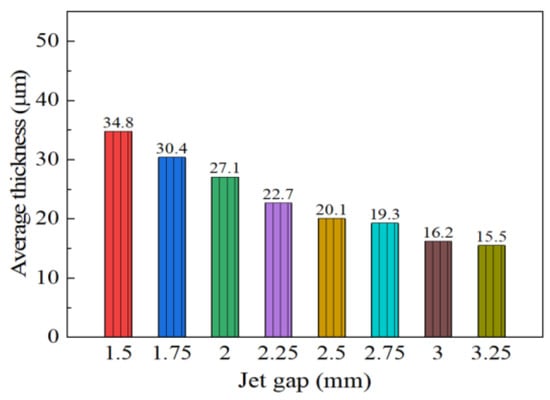
Figure 4.
Effect of varying jet gap on average coating thickness.
Figure 5 represents the Ni–Co–P coating deposited at a jet gap of 1.5 and 3.25 mm. From the figure, it is evident that the coating was uniform and defect free.
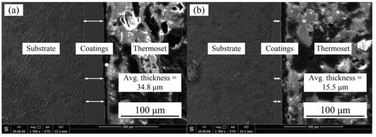
Figure 5.
SEM images of Ni–Co–P coatings deposited with a jet gap: (a) 1.5 mm and (b) 3.25 mm.
3.2. Effect of Varying Reciprocating Sweep Speed and Jet Gap on the EDS Patterns of Ni–Co–P Alloy Coatings
The effects of reciprocating sweep speed variation with a constant jet gap of 2.0 mm on Ni–Co–P alloy coatings’ EDS patterns is shown in Figure 6a. From Figure 6a, it can be seen that the content of Co element in Ni–Co–P alloy coatings at a reciprocating sweep speed of 100 mm/s was 38.75 wt.%. It is clear that with the increase in reciprocating sweep speed, the content of Co element in the deposit first increased and then decreased. Figure 6b displays the influence of jet gap variation with a constant reciprocating sweep speed of 175 mm·s−1 on the Ni–Co–P alloy coatings’ EDS patterns. It can be seen that the content of Co element in Ni–Co–P alloy coatings at a jet gap of 1.5 mm was 43.41 wt.%. Increase in jet gap caused the content of Co element in the deposit to first increase then decrease. A combination of Figure 6a,b indicate that the content of Co element in the deposit reached a maximum value of 47.66 wt.% when the reciprocating sweep speed was 175 mm·s−1 and the jet gap was 2.0 mm.
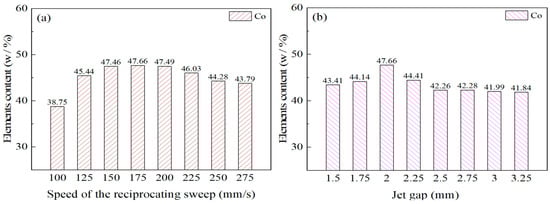
Figure 6.
Element content for Ni–Co–P alloy coatings deposited with varying: (a) reciprocating sweep speeds; (b) jet gaps.
3.3. Effect of Varying Reciprocating Sweep Speed and Jet Gap on Ni–Co–P Alloy Coating XRD Patterns
Figure 7a,b displays the Ni–Co–P alloy coatings’ XRD patterns synthesized with varying reciprocating sweep speeds and jet gaps. It is evident from the images that the deposited Ni–Co–P coatings exhibited three distinct peaks at 2θ = 44.56°, 51.79°, and 76.25°, which corresponded to the diffraction of the Nickel (111), (200), and (220), respectively. Figure 7a,b show that variation of reciprocating sweep speed and jet gap exhibited no distinct influence on either phase structure or peak intensities of Ni–Co–P coatings, but there was clear indication that a distinct preferred orientation in the (111) plane was evident. Additionally, a face-centered cubic (FCC) structure was exhibited by the deposited coatings. Some Ni atoms existing in the face-centered cubic Ni lattice were displaced by Co atoms and the Ni and Co atoms combined to form an α-phase solid solution. The Ni–Co alloy coatings exhibited single phase of face-centered cubic (FCC) structure at low Co content and this conforms to past reported findings [14]. Phosphorus diffraction peaks were not distinct, and this was associated with phosphorus combining with Ni and Co atoms to form a solid solution [34].
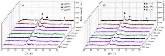
Figure 7.
XRD patterns for Ni–Co–P alloy coatings deposited with varying: (a) reciprocating sweep speeds; (b) jet gaps.
3.4. Effect of Varying Reciprocating Sweep Speed and Jet Gap on the Microhardness of Ni–Co–P Alloy Coatings
Figure 8a shows the microhardness of Ni–Co–P alloy coatings deposited as a function of reciprocating sweep speed variation. It is evident that microhardness increased from 620 HV0.1 at 100 mm·s−1 to 635 HV0.1 at 175 mm·s−1. This marked the highest value of microhardness achieved. Further increase in reciprocating sweep speed caused a subsequent decrease in microhardness, reaching a minimum value of 570 HV0.1 at 275 mm·s−1. This phenomenon may be associated with an increase in Co content in the Ni–Co–P alloy coatings. Going by partial EDS data illustrated in Table 2, it is clear that with increase in reciprocating sweep speed, the highest content of Co attained was 47.66 wt.% at 175 mm·s−1. Therefore, a suggestion that Co content significantly influenced the Ni–Co–P coatings’ microhardness can be considered. Increase in the reciprocating sweep speeds leads to the Co reaching a maximum value, which was associated with an increase in Co2+ metallic ion diffusion in the plating solution in the direction of the cathode surface [35]. As a consequence, solid solution strengthening improved the coatings’ microhardness owing to the combination of Ni and Co elements to form a solid solution. Once the optimum reciprocating sweep speed had been achieved, any further increase in reciprocating sweep speed resulted in the content of Co decreasing, which caused a consequential microhardness decrease. From Figure 7a, there is clear indication that an obvious preferred orientation in the (111) plane was evident for coatings deposited with varying reciprocating sweep speeds. Zimmerman et al. [36] found that nanocrystalline Ni coatings, having a preferred (111) crystallographic orientation, have better microhardness compared to those with (200) orientation. As such, the preferred orientation of the Ni–Co–P alloy coatings can be associated with the microhardness increase [36]. Similar findings were presented by Li et al. [37], whereby the crystalline structural change coupled with Co distribution and content were related to microhardness variation. A further increase in reciprocating sweep speed caused a subsequent decrease in microhardness, reaching a minimum value of 570 HV0.1 at 275 mm·s−1. Once the optimum reciprocating sweep speed had been achieved, any further increase in reciprocating sweep speed resulted in a decrease in Co content, and a corresponding decrease in microhardness.
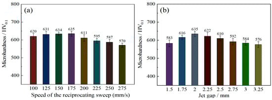
Figure 8.
Microhardness of Ni–Co–P alloy coatings deposited with varying: (a) reciprocating sweep speeds; (b) jet gaps.
Table 2.
Partial data of Ni–Co–P alloy coatings with varying reciprocating sweep speeds and jet gaps.
Figure 8b depicts the interaction effect between the jet gap and the microhardness of coatings. It is evident that the microhardness of Ni–Co–P coatings corresponded to 583 HV0.1 at a jet gap of 1.5 mm. Increase in the jet gap increased the hardness of the coating, reaching a maximum value of 635 HV0.1 at a jet gap of 2.0 mm. However, further increase in the jet gap to 3.25 mm caused a subsequent decrease in microhardness to 576 HV0.1. The above phenomena may be explained by the content of Co in the Ni–Co–P alloy coatings. Going by partial EDS data shown in Table 2, it is evident that with the increase in jet gap, the content of Co reached the highest content of 47.66 wt.% at 2.0 mm. A suggestion can therefore be made that the content of Co significantly influenced the Ni–Co–P coatings’ microhardness. Jet gap increase led to the Co content reaching a maximum value and this was associated with increased Co2+ metallic ion diffusion in the plating bath in the direction of the cathode [35]. A solid solution was formed at the cathode as the Ni and Co elements combined, and as a result, solid solution strengthening improved the microhardness of the coatings. From Figure 7b, it is clear that a distinct preferred orientation in the (111) plane was observed for coatings deposited with varying reciprocating sweep speeds. As such, preferred orientation of the Ni–Co–P alloy coatings can be associated with microhardness increase. However, further increase in the jet gap to 3.25 mm caused a subsequent decrease in microhardness to 576 HV0.1. This can be attributed to a decrease in Co content with further an increase in the jet gap.
Table 2 shows the relationship between Co content and varying reciprocating sweep speed as well as varying jet gap.
The optical microscopy image of the Vickers indent for Ni–Co–P coatings deposited at a varying reciprocating sweep speed of 175 mm·s−1 and a jet gap of 2.0 mm is illustrated in Figure 9. The absence of microcracks after the indenting indicated that the deposited coatings were compact. As such, it can be suggested that a load bearing Ni–Co–P matrix has significant resistance to formation and propagation of microcracks.
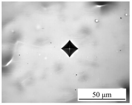
Figure 9.
Optical microscopy image of the Vickers indent for Ni–Co–P coatings deposited at 2.0 mm, and 175 mm·s−1.
3.5. Effect of Varying Reciprocating Sweep Speed and Jet Gap on the Friction resistance of Ni–Co–P Alloy Coatings
The influence of reciprocating sweep speed variation on friction resistance of coatings was shown in Figure 10a. It is evident that the wear scar width of the samples first decreased from 491 to 460 µm with increase in reciprocating sweep speed from 100 to 175 mm·s−1, and then increased to 496 µm with further increase in reciprocating sweep speed to 275 mm·s−1. Figure 10b shows the effect of varying jet gap on the friction resistance of Ni–Co–P coatings. It is evident that there was significant change in the Ni–Co–P alloy coatings’ wear track width. The wear track width of the coatings first decreased from 473 to 460 µm with increase in the jet gap from 1.5 to 2.0 mm. A further increase in the jet gap to 3.25 mm caused the wear scar width of samples to increase to 518 µm and this marked the largest value of wear scar width achieved over the tested range. The coating’s wear resistance has been associated with the microhardness and friction coefficient of a material in a mathematical relationship called Archard’s law, whereby material hardness is inversely proportional to wear loss of a material [38]. It is well known that the microhardness and friction coefficient have a great influence on the coating’s wear resistance. A lower coefficient of friction and a higher microhardness indicates better wear resistance [39]. It is evident from the test results that there was no considerable variation in the friction coefficient of 0.6. Therefore, a postulation can be made that the influence of Ni–Co–P alloy coating microhardness on the wear resistance is greater than that of friction coefficient. From Figure 9, it is evident that the microhardness of coatings attained the highest microhardness of 635 HV0.1 at a jet gap of 2.0 mm and a reciprocating sweep speed of 175 mm·s−1. With these parameter combinations, the Ni–Co–P alloy coatings exhibited the narrowest wear track width which indicated the best wear resistance. This conforms to Archard’s law and it indicates that the microhardness of coatings was a significant factor influencing the wear resistance of the deposited coatings.
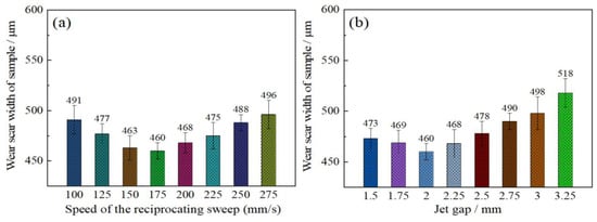
Figure 10.
Wear resistance of Ni–Co–P alloy coatings as a function of varying: (a) reciprocating sweep speed; (b) jet gap.
Figure 11 shows the SEM micrographs and LSCM 3D morphologies of wear tracks of Ni–Co–P alloy coatings deposited at varying reciprocating sweep speeds and jet gaps. It can be seen from Figure 11a–d that there were bright and dark areas on the surface of the wear tracks. At a reciprocating sweep speed of 175 mm·s−1 and a jet gap of 1.5 mm (Figure 11c,g), the furrow in Ni–Co–P alloy coatings became shallow and had little surface adhesion. Furthermore, it can be seen from Figure 11e–h1 that the average wear scar depths of the samples were 12.2 µm, 13.8 µm, 10.7 µm and 15.4 µm, respectively.
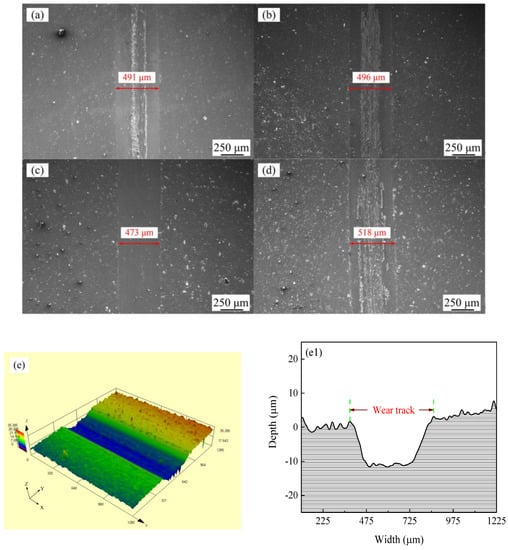
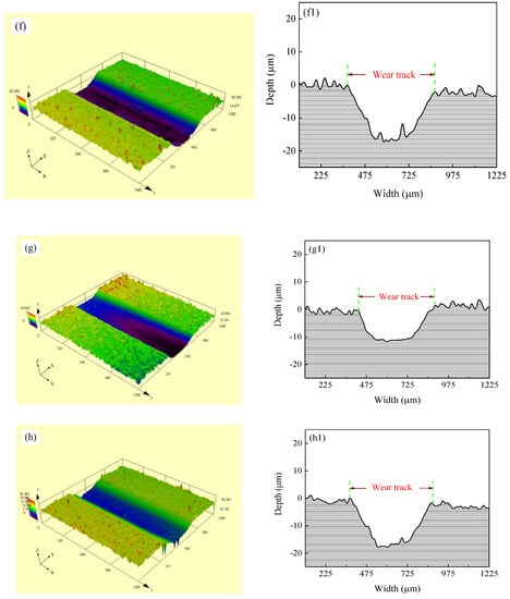
Figure 11.
SEM micrographs and laser scanning confocal microscopy (LSCM) 3D morphologies of worn surfaces of Ni–Co–P alloy coatings: (a) and (e–e1) 100 mm·s−1, 2.0 mm; (b) and (f–f1) 275 mm·s−1, 2.0 mm; (c) and (g–g1) 1.5 mm, 175 mm·s−1; (d) and (h–h1) 3.25 mm, 175 mm·s−1.
3.6. Effect of Varying Reciprocating Sweep Speed and Jet Gap on Ni–Co–P Alloy Coatings’ Seawater Corrosion Resistance
3.6.1. Influence of Reciprocating Sweep Speed Variation on Ni–Co–P Alloy Coatings’ Seawater Corrosion Resistance
Figure 12 presents corrosion curves of coatings deposited with varying reciprocating sweep speeds ranging from 100, 125, 150, 175, 200, 225, 250, to 275 mm·s−1 at 2.0 mm. Table 3 presents corresponding values for corrosion current densities (Icorr), anodic Tafel slopes (βa), cathodic Tafel slopes (βc), corrosion potentials (Ecorr), corrosion rates, and polarization resistances (Rp). The polarization resistances (Rp) were obtained from the potentiodynamic polarization curves of Figure 12 [40,41]. Polarization resistance (Rp) corresponds to an important index used to evaluate the corrosion resistance of coatings. A high polarization resistance (Rp) corresponds to better corrosion resistance. The opposite is also true [42,43,44]. It is evident from Figure 12 and Table 3 that the Ni–Co–P alloy coatings’ seawater corrosion resistance exhibited an observable change with increased reciprocating sweep speed. When the reciprocating sweep speed was 100 mm·s−1, a corrosion current density (Icorr) of 10.73 µA·cm−2, a corrosion rate of 141.9 µm·year−1, coupled with a polarization resistance (Rp) of 4.38 kΩ·cm−2 were obtained for the coatings. Increase in the reciprocating sweep speed lead to an increase in the polarization resistance (Rp) of the coatings, reaching a maximum value of 28.32 kΩ·cm−2 at 175 mm·s−1. The large polarization resistance (Rp) indicated a significant improvement in seawater corrosion resistance. Further increasing the reciprocating sweep speed to 275 mm·s−1 resulted in a decrease in the polarization resistance (Rp) of the coatings reaching a value of 7.99 kΩ·cm−2.
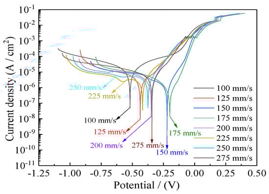
Figure 12.
Effect of varying reciprocating sweep speed on Ni–Co–P alloy coatings’ corrosion curves in artificial seawater.
Table 3.
Polarization resistance data obtained from Figure 12.
The phenomena may be explained by the composition of the surface oxide and Co element content. After the jet electrodeposition process was complete, the samples were exposed to the air. Oxides of Nickel and Cobalt were formed on the surface, which effectively hindered polarization when the coating was immersed in an artificial seawater corrosive environment. Furthermore, the increase in content of Co in the coating improved seawater corrosion resistance. According to the Figure 6, there was an initial increase in the content of Co element in the deposit followed by a decrease as the reciprocating sweep speed increased. The highest Co content attained for the Ni–Co–P alloy coatings was 47.66 wt.% at a reciprocating sweep speed of 175 mm·s−1. The increase in Co content in Ni–Co–P alloy coatings improved the corrosion resistance of Ni–Co–P alloy coatings [45]. Similar conclusions were made previously by Fan et al. [46], whereby the addition of Co improved the corrosion resistance of a Sn-0.7Cu solder alloy under a salt spray atmosphere. Additionally, increase in the content of Co caused a decrease in the mass loss rate of the alloy.
To further demonstrate the improvement of coating seawater corrosion resistance, electrochemical impedance spectroscopy (EIS) was relied on to investigate the seawater corrosion resistance of coatings as a powerful compliment to the Tafel curves. Several physical parameters that correspond to the seawater corrosion resistance of Ni–Co–P alloy coatings were obtained from EIS. The effect of reciprocating sweep speed on Ni–Co–P alloy coatings’ EIS profiles in artificial seawater is shown in Figure 13. The Nyquist plots of coatings are shown in Figure 13a. Generally, a larger impedance semicircle diameter indicates superior coating polarization resistance [47]. It is evident that with the increase in reciprocating sweep speed, there was an initial increase in the coatings’ impedance semicircle diameter followed by a decrease. The impedance semicircle diameter of the coatings was largest when the reciprocating sweep speed was 175 mm·s−1, which indicated excellent corrosion protection of Ni–Co–P alloy coatings. Figure 13b depicts Bode plots for the coatings (impedance modulus |Z| as a function of frequency). From the figure, it is evident that the impedance spectra were much closer at a high frequency for all the coatings deposited with increase in reciprocating sweep speed. However, the impedance modulus (|Z|) for 175 mm·s−1 was largest at low frequency in the Bode plots. The higher impedance modulus (|Z|) value indicates better seawater corrosion protection performance. In addition, the impedance modulus (|Z|) in the Bode plots was extremely smooth and the slope exhibited no distinct fluctuation, which indicated that the coatings exhibited uniform polarization without pitting in an artificial seawater environment.
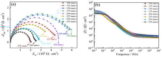
Figure 13.
Effect of reciprocating sweep speed on Ni–Co–P alloy coatings’ electrochemical impedance spectra in artificial seawater: (a) Nyquist plots (Zre—Zim); (b) Bode plots (F—|Z|).
Figure 14 presents the equivalent circuit models used for the Ni–Co–P alloy coatings, where Rs represents the solution resistance, the Cc and Rc are the resistance and capacitance of the coating, Cdl is double layer capacitance, and Rct is the charge transfer resistance [48]. A previous study [49,50] showed that a higher value of Rct implied more inefficient charge transfer across the electrode/electrolyte interface, which could increase the possibility of charge recombination and thus improve the corrosion resistance. Table 4 lists the well-fitting results obtained from Figure 14. As shown in Figure 14 and Table 4, it is evident that a stable state was exhibited by the test system owing to Rs not being obvious. At a reciprocating sweep speed of 100 mm·s−1, the coatings’ charge transfer resistance (Rct) was 2.02 × 10⁴ Ω·cm−2. At first, there was an increase in charge transfer resistance (Rct) of the coatings with increase in reciprocating sweep speed reaching a value of 5.04 × 10⁴ Ω·cm−2 at 175 mm·s−1. This marked the maximum value of charge transfer resistance (Rct) achieved, which indicated that the Ni–Co–P alloy coating provided effective protection for the 45 steel substrates. Further increase in the reciprocating sweep speed caused the charge transfer resistance (Rct) to decrease, reaching a value of 1.75 × 10⁴ Ω·cm−2 at 275 mm·s−1. The results obtained concur with the polarization curves.
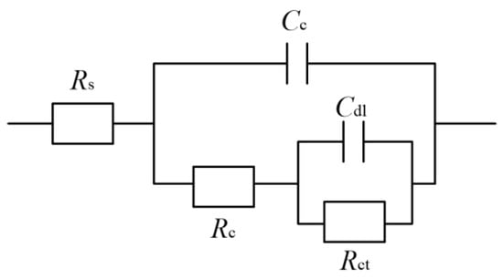
Figure 14.
Ni–Co–P alloy coatings’ equivalent circuit model in artificial seawater.
Table 4.
Impedance spectrum fitting value of Ni–Co–P alloy coatings deposited with varying reciprocating sweep speeds.
3.6.2. Influence of Jet Gap Variation on Ni–Co–P Alloy Coatings’ Seawater Corrosion Resistance
Figure 15 presents the corrosion curves of Ni–Co–P alloy coatings deposited with varying jet gaps ranging from 1.5, 1.75, 2.0, 2.25, 2.5, 2.75, 3.0, to 3.25 mm at 175 mm·s−1. Additionally, Table 5 presents corresponding values for corrosion current densities (Icorr), anodic Tafel slopes (βa), cathodic Tafel slopes (βc), corrosion potentials (Ecorr), corrosion rates, and polarization resistances (Rp). The polarization resistances (Rp) were obtained from the potentiodynamic polarization curves of Figure 15. It is evident from Figure 15 and Table 5 that the Ni–Co–P alloy coatings’ seawater corrosion resistance exhibited an observable change with increase in the jet gap. At a jet gap of 1.5 mm the polarization resistance (Rp) was 9.49 kΩ·cm−2. Initially, increase in the jet gap caused an increase in the polarization resistance (Rp) of the coatings, reaching a maximum value of 28.32 kΩ·cm−2 at 2.0 mm. The phenomena may be attributed to the increase in the Co element content.
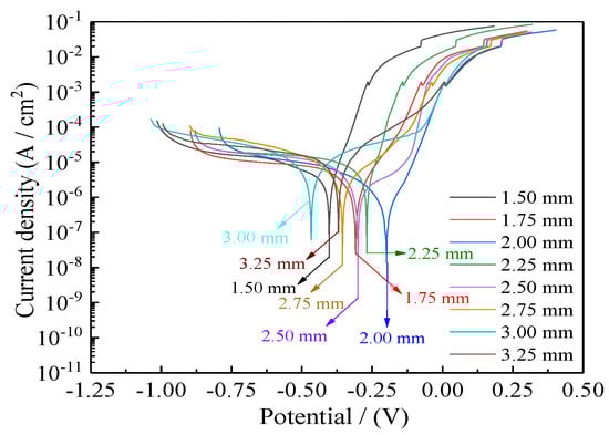
Figure 15.
Influence of jet gap on Ni–Co–P alloy coatings’ corrosion curves in artificial seawater.
Table 5.
Polarization data obtained from Figure 15.
From Figure 6, there was an initial increase in the content of Co element in the deposit followed by a decrease as the jet gap increased. The highest Co content attained for the Ni–Co–P alloy coatings was 47.66 wt.% at a jet gap of 2.0 mm. Cobalt is less noble than Ni, and as such, Co is more reactive than Ni. As such, the Co content increase in the deposited coatings promoted adsorption and aggregation of the products of corrosion. As a result, there was an increase in the area of coverage by products of corrosion on the surface, which further improved the coatings’ corrosion resistance. The large polarization resistance (Rp) indicated that seawater corrosion resistance of the coating was greatly improved. Further increase in the jet gap caused a decrease in the polarization resistance (Rp) of the coatings, reaching a minimum value of 4.81 kΩ·cm−2 at 3.25 mm. This indicated a decrease in the corrosion resistance of the coatings which can be associated with decreasing Co element content in the coatings.
To further demonstrate the improvement of the coatings’ seawater corrosion resistance, electrochemical impedance spectroscopy (EIS) was relied on to investigate seawater polarization resistance of coatings as a compliment to Tafel curves. Figure 16 presents the influence of jet gap on Ni–Co–P alloy coatings’ EIS in artificial seawater. The coatings’ Nyquist plots are depicted in Figure 16a. It is evident that with the increase in jet gap, there was an initial increase in the coatings’ impedance semicircle diameter followed by a decrease. The impedance semicircle diameter of the coatings was largest when the jet gap was 2.0 mm, which indicated excellent the corrosion protection of Ni–Co–P coatings. Figure 16b depicts Bode plots of the coatings (impedance modulus |Z| as a function of frequency). From Figure 16b, it is evident that the impedance spectra were much closer at a high frequency for all the coatings deposited with an increase in jet gap. However, the impedance modulus (|Z|) for 2.0 mm was largest at low frequency in the Bode plots. Higher impedance modulus (|Z|) value indicates better seawater corrosion protection performance. In addition, the impedance modulus (|Z|) in the Bode plots was extremely smooth with no obvious fluctuation for the slope, which indicated that the coatings exhibited uniform polarization without pitting in artificial seawater environment. Table 6 presents the well-fitting results derived from Figure 16. From Figure 16 and Table 6, it is evident that a stable state was exhibited by the test system owing to Rs not being obvious. At a jet gap of 1.5 mm, the coatings’ charge transfer resistance (Rct) was 2.05 × 10⁴ Ω·cm−2. At first, there was an increase in charge transfer resistance (Rct) of the coatings with the increase in jet gap reaching a value of 5.04 × 10⁴ Ω·cm−2 at 2.0 mm. This marked the maximum value of charge transfer resistance (Rct) achieved, which indicated that the Ni–Co–P alloy coating provided effective protection for the 45 steel substrates. Further increase in the jet gap caused the charge transfer resistance (Rct) to decrease, reaching a value of 1.17 × 10⁴ Ω·cm−2 at 3.25 mm. The results obtained concur with the polarization curves.
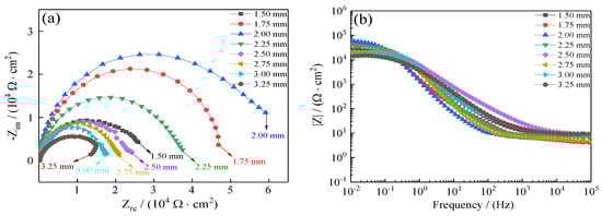
Figure 16.
Influence of jet gap variation on Ni–Co–P alloy coatings’ electrochemical impedance spectra in artificial seawater: (a) Nyquist plots (Zre—Zim); (b) Bode plots (F—|Z|).
Table 6.
Impedance spectrum fitting value of Ni–Co–P alloy coatings with varying jet gaps.
Figure 17 shows the corrosion resistance of 45 steel substrate and Ni–Co–P alloy coatings when immersed in artificial seawater. The polarization resistance (Rp) of 45 steel substrates obtained from the potentiodynamic polarization curves of Figure 17a was 4.05 kΩ·cm−2. The polarization resistance (Rp) of Ni–Co–P alloy coatings was 28.32 kΩ·cm−2, which showed that the Ni–Co–P alloy coatings could effectively protect type 45 steel substrates. Figure 17b,c displays the Nyquist plots and Bode plots of 45 steel substrate and Ni–Co–P alloy coatings. It can be seen from Figure 17b,c that the impedance semicircle diameter of Ni–Co–P alloy coatings was much larger than that of 45 steel substrate, which showed that the Ni–Co–P alloy coatings had excellent seawater corrosion resistance.
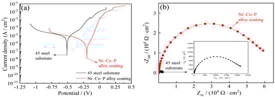
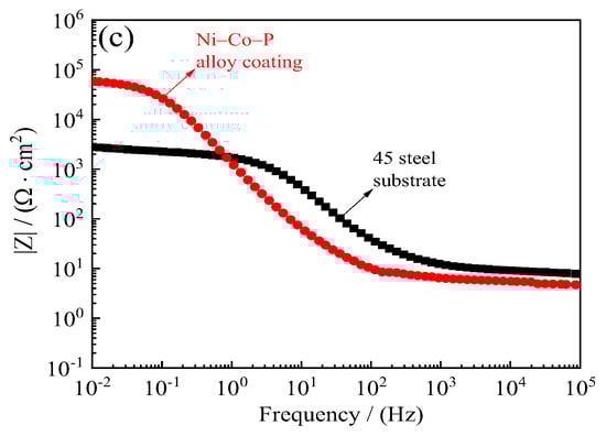
Figure 17.
Corrosion resistance of 45 steel substrate and Ni–Co–P alloy coatings in artificial seawater: (a) Corrosion curves; (b) Nyquist plots (Zre—Zim); (c) Bode plots (F—|Z|).
4. Conclusions
In this work, 45 steel substrates were coated with Ni–Co–P alloy coatings using a self-made jet electrodeposition equipment to investigate the influence of reciprocating sweep speed and jet gap variation on coating properties. From the experimental testing and results obtained, the following conclusions were made:
- (1)
- The chemical composition, thickness, and cross-section morphologies of Ni–Co–P alloy coatings were affected by reciprocating sweep speed and jet gap. When the reciprocating sweep speed was 175 mm·s−1 and the jet gap was 2.0 mm, the contents of Co elements in the deposit attained the highest content of 47.66 wt.%. Variation of reciprocating sweep speed and jet gap exhibited no distinct influence on either peak intensities or phase structure of Ni–Co–P coatings, but a distinct preferred orientation in the (111) plane was evident.
- (2)
- Further increase in reciprocating sweep speed and jet gap caused an initial increase in the microhardness followed by a decrease, with the highest microhardness attained being 635 HV0.1. The wear track width of Ni–Co–P alloy coatings attained the narrowest width of 460 µm at a jet gap of 2.0 mm and a reciprocating sweep speed of 175 mm·s−1.
- (3)
- Ni–Co–P alloy coatings’ seawater corrosion resistance exhibited an observable change with increased reciprocating sweep speed and jet gap. The polarization curve in the electrochemical test showed that the coatings exhibited the highest polarization resistance (Rp) of 28.32 kΩ·cm−2 when the reciprocating sweep speed was 175 mm·s−1 and the jet gap was 2.0 mm, which indicated that the Ni–Co–P alloy coatings deposited under these conditions had the best seawater corrosion resistance.
Author Contributions
Conceptualization, Y.Z. and M.K.; methodology, Y.Z., S.M.N., and L.Y.; validation, Y.Z. and L.Y.; formal analysis, Y.Z. and S.M.N.; investigation, M.J. and L.Y.; resources, M.K.; writing—original draft preparation, Y.Z. and S.M.N.; writing—review and editing, Y.Z., S.M.N., and M.K.; visualization, Y.Z.; supervision, M.K.; project administration, M.K. and J.Z.; funding acquisition, M.K. All authors have read and agreed to the published version of the manuscript.
Funding
This research was funded by the Research and Innovation Program for Graduate Students in Jiangsu, Grant No. KYCX19_0607.
Acknowledgments
EDS spectra of Ni–Co–P alloy coatings’ surface were analyzed by Research Institute of Nanjing Chemical Industry Group, Sinopec.
Conflicts of Interest
The authors declare no conflict of interest. The funders had no role in the design of the study; in the collection, analyses, or interpretation of data; in the writing of the manuscript; or in the decision to publish the results.
References
- Mbugua, N.S.; Kang, M.; Zhang, Y.; Ndumia, J.N.; Gbenontin, V.B.; Yao, L. Electrochemical deposition of Ni, NiCo alloy and NiCo–ceramic composite coatings—A critical review. Materials 2020, 13, 3475. [Google Scholar] [CrossRef] [PubMed]
- Schlesinger, M.; Paunovic, M. Modern Electroplating; John Wiley & Sons: New York, NY, USA, 2011. [Google Scholar]
- Nyambura, S.M.; Kang, M.; Zhu, J.; Liu, Y.; Zhang, Y.; Ndumia, J.N. Synthesis and characterization of Ni-W/Cr2O3 nanocomposite coatings using electrochemical deposition technique. Coatings 2019, 9, 815. [Google Scholar] [CrossRef]
- Liu, X.; Zhao, X.; An, Y.; Hou, G.; Li, S.; Deng, W.; Zhou, H.; Chen, J. Effects of loads on corrosion-wear synergism of NiCoCrAlYTa coating in artificial seawater. Tribol. Int. 2018, 118, 421–431. [Google Scholar] [CrossRef]
- Zhao, D.; Xu, X.; Xu, B. Corrosion behavior of Ni-Zn-P alloy coating in artificial seawater. Surf. Technol. 2016, 4, 169–174. (In Chinese) [Google Scholar]
- Fang, X.; Du, X.; Gao, S.; Zhang, X. Effect of artificial seawater temperature on electrochemical behavior of Ni-P and Ni-Cu-P alloy coatings. Trans. Nonferr. Met. Soc. China. 2018, 6, 1176–1181. (In Chinese) [Google Scholar]
- Wang, H.; Wu, Q.; Zhang, Z.; Yao, S.; Zhang, W. Corrosion behavior and mechanism of Ni-Sn-P alloy coatings in artificial sea water. CIESC J. 2013, 4, 1359–1363. (In Chinese) [Google Scholar]
- Pang, J.; Li, Q.; Wang, W.; Xu, X.; Zhai, J. Preparation and characterization of electroless Ni-Co-P ternary alloy on fly ash cenospheres. Surf. Coat. Technol. 2011, 205, 4237–4242. [Google Scholar] [CrossRef]
- Fetohi, A.E.; Hameed, R.M.A.; El-Khatib, K.M.; Souaya, E.R. Ni-P and Ni-Co-P coated aluminum alloy 5251 substrates as metallic bipolar plates for PEM fuel cell applications. Int. J. Hydrog. Energy 2012, 37, 7677–7688. [Google Scholar] [CrossRef]
- Khan, M.R.; Nicholson, E.L. Magnetic properties and microstructure of electroless plated Co-Ni-P and Co-P thin films for longitudinal recording. J. Magn. Magn. Mater. 1986, 54, 1654–1656. [Google Scholar] [CrossRef]
- Lew, K.S.; Raja, M.; Thanikaikarasan, S.; Kim, T.; Kim, Y.D.; Mahalingam, T. Effect of pH and current density in electrodeposited Co-Ni-P alloy thin films. Mater. Chem. Phys. 2008, 112, 249–253. [Google Scholar] [CrossRef]
- Shen, L.; Wang, Y.; Jiang, W.; Liu, X.; Wang, C.; Tian, Z. Jet electrodeposition multilayer nickel on the surface of sintered NdFeB and corrosion behaviors. Corros. Eng. Sci. Technol. 2017, 52, 311–316. [Google Scholar] [CrossRef]
- Rajput, M.S.; Pandey, P.M.; Jha, S. Micromanufacturing by selective jet electrodeposition process. Int. J. Adv. Manuf. Technol. 2015, 76, 61–67. [Google Scholar] [CrossRef]
- Qiao, G.; Jing, T.; Wang, N.; Gao, Y.; Zhao, X.; Zhou, J.; Wang, W. High-speed jet electrodeposition and microstructure of nanocrystalline Ni-Co alloys. Electrochim. Acta 2005, 51, 85–92. [Google Scholar] [CrossRef]
- Rajput, M.S.; Pandey, P.M.; Jha, S. Experimental investigations into ultrasonic-assisted jet electrodeposition process. J. Eng. Manuf. 2014, 228, 682–694. [Google Scholar] [CrossRef]
- Wang, G.F.; Shen, L.D.; Huang, Y.H. Jet electrodeposition of bulk nanocrystalline nickel with real-time polishing. Int. J. Electrochem. Sci. 2012, 7, 10818–10824. [Google Scholar]
- Zheng, X.; Wang, M.; Song, H.; Wu, D.; Liu, X.; Tan, J. Effect of ultrasonic power and pulse-on time on the particle content and mechanical property of Co-Cr3C2 composite coatings by jet electrodeposition. Surf. Coat. Technol. 2017, 325, 181–189. [Google Scholar] [CrossRef]
- Tang, Z.; Ye, X.; Tan, J.; Zhang, Q. Effect of flow of bath on properties of Co-Ni alloy coating prepared by jet electrodeposition. Electroplat. Pollut. Control 2020, 3, 11–14. [Google Scholar]
- Wang, M.; Tan, J.; Wu, D.; Lan, L. Process optimization of preparing Co-Cr3C2 composite coatings by jet-electrodeposition. China Surf. Eng. 2016, 4, 75–85. [Google Scholar]
- Zhang, Q.; Tan, J.; Xie, F.; Lan, L.; Meng, L.; Zang, Y.; Zhu, X. Effect of jet electrodeposition current density on microstructure and properties of Co-Ni-nano Cr3C2 composite coatings. Surf. Technol. 2020, 5, 191–199. [Google Scholar]
- Cui, W.; Wang, K.; Xia, F.; Wang, P. Simulation and characterization of Ni–doped SiC nanocoatings prepared by jet electrodeposition. Ceram. Int. 2018, 44, 5500–5505. [Google Scholar] [CrossRef]
- Jiang, W.; Shen, L.; Qiu, M.; Wang, X.; Fan, M.; Tian, Z. Preparation of Ni-SiC composite coatings by magnetic field-enhanced jet electrodeposition. J. Alloys Compd. 2018, 762, 115–124. [Google Scholar] [CrossRef]
- Ning, D.; Yang, C.; Wu, H. Ultrafast Cu2+ recovery from waste water by jet electrodeposition. Sep. Purif. Technol. 2019, 220, 217–221. [Google Scholar] [CrossRef]
- Kim, H.; Kim, J.G.; Park, J.W.; Chu, C.N. Selective copper metallization of nonconductive materials using jet circulating electrodeposition. Precis. Eng. 2018, 51, 153–159. [Google Scholar] [CrossRef]
- Qiao, G.; Jing, T.; Mang, N.; Gao, Y.; Zhao, X.; Zhou, J.; Wang, W. Effect of current density on microstructure and properties of bulk nanocrystalline Ni-Co alloys prepared by JED. J. Electrochem. Soc. 2006, 153, C305–C308. [Google Scholar] [CrossRef]
- Parente, M.V.; Mattos, O.R.; Diaz, S.L.; De Lima-Neto, P.; Miranda, F.F. Electrochemical characterization of Ni-P and Ni-Co-P amorphous alloy deposits obtained by electrodeposition. J. Appl. Electrochem. 2001, 31, 677–683. [Google Scholar] [CrossRef]
- Yao, S.; Liu, B.; Guo, H.; Takao, S. Study of Ni-Co-P amorphous alloy electrodeposition and its properties. J. Chem. Ind. Eng. 1996, 1, 48–52. [Google Scholar]
- Li, H.; Kang, M.; Zhang, Y.; Niu, X.; Liu, C.; Jin, M. Influences of jet parameters on structure and wear resistance of Ni-Co-BN(h) nanocomposite coatings. China Surf. Eng. 2018, 2, 103–112. (In Chinese) [Google Scholar]
- Chen, H.; Liu, Z.; Shen, L.; Qiu, M.; Tian, Z.; Ge, M. Electrochemical polishing of monocrystalline silicon with specific crystallographic planes. Mater. Sci. Semicond. Process. 2017, 67, 8–13. [Google Scholar] [CrossRef]
- Zhang, Y.; Kang, M.; Yao, L.; Mbugua, N.S.; Jin, M.; Zhu, J. Study on the wear and seawater corrosion resistance of Ni-Co-P alloy coatings with jet electrodeposition in different jet voltages and temperatures of plating solution. Coatings 2020, 10, 639. [Google Scholar] [CrossRef]
- Wang, Y.; Zhang, J.; Kang, M. Experimental study on the depositing rate of jet-electrodeposition Ni-P alloy. Electromach. Mould. 2013, 1, 16–18. (In Chinese) [Google Scholar]
- Wang, M.; Du, N.; Zhao, Q.; Lu, X. Study of quick local electrodeposition by jet plating. Mater. Prot. 2006, 9, 49–50, 70, 73. (In Chinese) [Google Scholar]
- Liu, X.; Shen, L.D.; Qiu, M.B.; Tian, Z.J.; Wang, Y.H.; Zhao, K.L. Jet electrodeposition of nanocrystalline nickel assisted by controllable friction. Surf. Coat. Technol. 2016, 305, 231–240. [Google Scholar] [CrossRef]
- Li, Z.; Deng, Y.; Shen, B.; Liu, L.; Hu, W. Synthesis, characterization and microwave properties of Ni-Co-P hollow spheres. J. Alloys Compd. 2010, 491, 406–410. [Google Scholar] [CrossRef]
- Gilewicz, A.; Chmielewska, P.; Murzynski, D.; Dobruchowska, E.; Warcholinski, B. Corrosion resistance of CrN and CrCN/CrN coatings deposited using cathodic arc evaporation in Ringer’s and Hank’s solutions. Surf. Coat. Technol. 2016, 299, 7–14. [Google Scholar] [CrossRef]
- Zimmerman, A.F.; Palumbo, G.; Aust, K.T.; Erb, U. Mechanical properties of nickel silicon carbide nanocomposites. Mater. Sci. Eng. A 2002, 328, 137–146. [Google Scholar] [CrossRef]
- Li, B.; Zhang, W.; Li, D. Synthesis and properties of a novel Ni-Co and Ni-Co/ZrO2 composite coating by DC electrodeposition. J. Alloy Compd. 2020, 821, 153258. [Google Scholar] [CrossRef]
- Archard, J.F. Contact and rubbing of flat surfaces. J. Appl. Phys. 1953, 24, 981–988. [Google Scholar] [CrossRef]
- Zhang, Y.; Kang, M.; Fu, X.; Li, H.; Liu, Y. Surface structure and wear resistance of Ni-Co-P-BN(h)-Al2O3 binary nano composite coatings. Mater. Sci. Technol. 2019, 6, 55–66. [Google Scholar]
- Hu, X.; Qu, N. Enhanced corrosion resistance of nickel–cobalt/carborundum coatings formed by supergravity field-assisted electrodeposition. Thin Solid Films 2020, 700, 137923. [Google Scholar] [CrossRef]
- Sun, Y.; Huang, Y.J.; Fan, H.B.; Wang, Y.M.; Ning, Z.L.; Liu, F.Y.; Feng, D.F.; Jin, X.X.; Shen, J.; Sun, J.F.; et al. In vitro and in vivo biocompatibility of an Ag-bearing Zr-based bulk metallic glass for potential medical use. J. NonCryst. Solids 2015, 419, 82–91. [Google Scholar] [CrossRef]
- Yu, Z.; Ji, Z.; Tao, D.; Zhang, Q.; Liu, R. Research on a reversible superwetting behavior and its corrosion resistance. Appl. Surf. Sci. 2020, 517, 146145. [Google Scholar] [CrossRef]
- Wang, X.; Zhang, Y. Microstructures and corrosion resistance properties of as-cast and homogenized AlFeNiCuCr high entropy alloy. Mater. Chem. Phys. 2020, 254, 123440. [Google Scholar] [CrossRef]
- Shun, T.T.; Hung, C.H.; Lee, C.F. Formation of ordered/disordered nanoparticles in FCC high entropy alloys. J. Alloy Compd. 2010, 493, 105–109. [Google Scholar] [CrossRef]
- Kang, M.; Zhang, Y.; Li, H. Study on the performances of Ni-Co-P/BN(h) nanocomposite coatings made by jet electrodeposition. Procedia CIRP 2018, 68, 221–226. [Google Scholar] [CrossRef]
- Fan, J.; Liu, Z.; Zhai, H.; Wang, X.; Wang, Y.; Li, Y.; Zhou, X.; Wu, S.; Liu, J. Effect of Co content on the microstructure, spreadability, conductivity and corrosion resistance of Sn-0.7Cu alloy. Microelectron. Reliab. 2020, 107, 113615. [Google Scholar] [CrossRef]
- Li, B.; Zhang, W.; Huan, Y.; Zhang, W. Effect of SiC on corrosion and wear resistance of Ni-W coatings. Rare Met. Mater. Eng. 2017, 10, 381–386. [Google Scholar]
- Yu, D.; Tian, J.; Dai, J.; Wang, X. Corrosion resistance of three-layer superhydrophobic composite coating on carbon steel in seawater. Electrochim. Acta 2013, 97, 409–419. [Google Scholar] [CrossRef]
- Jayaraj, J.; Raj, A.S.; Srinivasan, A.; Ananthakumar, S.; Pillai, U.T.S.; Dhaipule, N.G.K.; Mudali, U.K. Composite magnesium phosphate coatings for improved corrosion resistance of magnesium AZ31 alloy. Corros. Sci. 2016, 113, 104–115. [Google Scholar] [CrossRef]
- Ji, X.J.; Luan, G.F.; Lyu, J.C.; Cui, L.Y.; Li, S.Q.; Zeng, R.C.; Wang, Z.L. Corrosion resistance and tunable release of ciproflfloxacin-loaded multilayers on magnesium alloy: Effects of SiO2 nanoparticles. Appl. Surf. Sci. 2020, 508, 145240. [Google Scholar] [CrossRef]


© 2020 by the authors. Licensee MDPI, Basel, Switzerland. This article is an open access article distributed under the terms and conditions of the Creative Commons Attribution (CC BY) license (http://creativecommons.org/licenses/by/4.0/).