Abstract
The friction surfacing technique is an advanced method for creating coatings of various materials onto the surface of a similar or dissimilar material substrate. In this method, there is no external source of heat energy, and all the heat energy required in this method is generated by friction. In this paper, a novel method of friction surfacing from the side of the consumable tool is introduced. The most significant difference in this technique is that material transfer will occur from the radial surface of the consumable tool as opposed to the end of the tool as in conventional friction surfacing. In lateral friction surfacing, the side of the rotating consumable tool is pressed against the substrate surface, which generates frictional heating and shear forces at the interface between tool and substrate. A layer of tool material is transferred from the consumable rod to the substrate surface as the tool moves across. In this study, 6063 aluminum alloy and AISI 1018 carbon steel are used as the materials of consumable tool and substrate, respectively. The impact of process factors, surface roughness values, tool mass loss, and deposition thickness are discussed in detail. The experimental results of this study reveal that lateral friction surfacing produces a very smooth ultra-thin deposition with full coverage, with coating layers with roughness values in the order of 1 µm. Additionally, there is no flash formed in this technique which reduces material consumption. Moreover, temperatures at the interface between the consumable tool and workpiece were measured to be lower than for that in friction surfacing from the end of the tool, which is beneficial for the metallurgical characteristics of the deposited material.
1. Introduction
Friction surfacing is a thermo-mechanical solid-state process for the deposition of dissimilar material. It is a relatively new variation of the friction stir welding process for modification of the surface properties of the substrate. Friction surfacing is a metallic deposition technique in which a rotating consumable tool deposits material onto a solid substrate, due to frictional heat generated between the rotating consumable rod and the substrate. In the process, the rotating consumable tool is forced against the substrate surface, which generates frictional heating and shear forces at the interface between tool and substrate. A layer of tool material can be transferred from the rod to the substrate surface as the consumable tool moves across.
The possibility of producing metal deposition without any metal melting makes this technique distinct from other conventional methods of coating. Klopstock and Neelands introduced this technique as a metal-deposition process in 1941 [1]. In this method, the friction deposition is feasible due to frictional heat generated between the substrate and rotating consumable tool which makes this technique a powerful alternative for creating metal deposition [2]. There has been a developing interest in employing the friction surfacing process in recent years. Friction surfacing has many applications in welding, coating, repair of defective components, hard surfacing, and corrosion protection. This process does not generate high temperatures; therefore, this technique is a suitable method capable of coating low melting point alloys [2]. This technique could be used to create friction deposition over dissimilar materials [3,4,5,6,7,8]. Other advantages of this technique, such as a negligible amount of distortion in the rod and workpiece, low amount of residual stress, and removal of defects like porosities, are noticeable. The friction deposition process has a lower specific energy consumption and a higher rate of material transfer than laser cladding and plasma arc welding techniques. In the surfacing technique, using the end of the consumable tool, there is the possibility of enhancing the efficiency of the bonding up to 5%, by tilting the tool along the deposition direction. In addition, flash formation is another imperative issue which can result in material loss of about 40–60% of the total tool consumed [9].
Chandrasekaran et al. studied conventional friction surfacing of aluminum, stainless steel, mild steel, inconel, and titanium as the consumable rods onto aluminum and mild steel as substrates. The results of their study show that inconel and steel rods were coated successfully onto mild steel, while the deposition of the aluminum rod was only successful under high axial load. The friction depositions of inconel, mild steel, and stainless steel onto aluminum substrate were successful, but deposition of titanium was not feasible [10]. Guo et al. [11] studied the possibility of friction deposition of AISI 316L as a consumable rod onto AISI 304 steel substrate. In this study, the experimental tests were performed under the protection of argon as the shielding gas to avoid oxidation. Increasing forced convection using argon shielding gas resulted in an increment in the average grain diameter within the coating. Friction surfacing of stainless steel 316L onto 304 substrates was investigated, and it was exhibited that the tool rotational speed employed in this process has a more significant influence on the microstructures of the coating surface than those in the cross-section [12]. Further investigations have been done to study the friction surfacing of dissimilar materials such as aluminum [13,14,15,16] and copper [17] onto steel, and steel onto aluminum [18,19,20,21,22].
Additionally, there are many investigations studying the effects of friction surfacing process factors with variations of materials [23,24,25,26,27,28,29,30]. In order to obtain high-quality coating in friction surfacing, a proper adoption of process parameters is essential. The process parameters of the friction surfacing technique have a significant influence on the coating width, thickness, microstructural evolution, and corrosion resistance. There are three main process parameters in the friction surfacing technique: tool rotational speed, substrate travel speed, and the load applied on the consumable tool. Many investigations have been done to evaluate the friction surfacing process under different process parameters [2].
Kumar et al. [23] studied the influences of process parameters on dimensions of the deposition in friction surfacing of 6063 aluminum alloy on IS2062 substrate. It was concluded that some physical factors such as axial load, tool rotational speed, and traverse speed were the most important parameters for dimensions of deposition layers. The coating thickness decreased as the coating width increased. Furthermore, higher combined values of table traverse speed and axial load leads to greater deposition thickness and width. Gandra et al. [31] evaluated the friction deposition of 6082-T6 aluminum alloy onto 2024-T3 aluminum alloy substrate, with special attention to the effects of process parameters including axial load, tool rotational speed, and table travel speed. The experimental results indicated that, to increase coating thickness and width, low tool rotation speeds and table travel speed should be considered.
Shinoda et al. [32] established a procedure to study the effects of process factors on the coating quality. In this method, a 1 mm thick hard coating was formed using the friction surfacing process. It was concluded that the rotational speed of the tools has a significant influence on the hardness of the coating. This study shows that a harder deposition can be generated when the consumable rod has a lower rotational speed. In another investigation [33], Rafi et al. studied the friction deposition of steel H13 onto low carbon steel substrate. In this study, the axial load was constant, while the rod rotational speed and the table traverse speed were varied. The results reveal that using a higher rod rotational speed results in a narrower deposition layer compared to the layers created at a lower rod rotational speed. Further improvement in friction deposition requires development in analytical modeling of the process, which improves the optimization methods of the process [34]. The effects of friction surfacing process parameters in friction deposition of AA6351-T6 onto AA5052-H32 using a milling machine were studied in [35]. In this investigation, the tool feed rate was considered as a control process parameter, and the superficial and microstructural characterization of the deposition was studied. The result of the friction surfacing process shows that this technique could be used to create homogeneous coating layers. In this investigation, the hardness value in the central region of the deposition layer decreased by 15.87% with respect to the as-received substrate material.
Kumar et al. [36] has done an investigation to determine the appropriate process parameters for the friction surfacing process. Analysis proved that lower deposition thickness could be obtained by using a higher axial force. Fitseva et al. [37] investigated the influence of tool rotational speed on mechanical properties, microstructures, and grain size evolution during the friction surfacing of a Ti-6Al-4V consumable rod onto a Ti-6Al-4V plate in a hot-rolled condition. In a recent investigation [38], Monel 500 was effectively deposited onto mild steel AISI 1012. In this study, a computing modeling using the fuzzy logic technique was developed to correlate the process parameters to the thickness and width of the deposition.
Ratheea et al. [39] studied the issues and strategies in developing surface composites through friction stir processing. This study has a special focus on the important process parameters involved in the surface composite fabrication process, and the mechanical properties and microstructures associated with these process parameters. In [40], friction deposition of AA5083 as a consumable tool onto AA5052 substrate was investigated. In this study, the finite element analysis was utilized to stimulate the thermo-mechanical behavior of the friction surfacing process. In another investigation [41], finite element analysis was used to study the friction surfacing of a 2024 aluminum alloy consumable rod onto an 1050 aluminum alloy substrate. This study revealed that as the tool rotational speed is increased, the axial feeding rate is decreased.
The friction surfacing process can be used as a new method for filling the keyholes made by the friction stir welding process. Huang et al. [42] investigated using a semi-consumable joining tool through the filling friction stir welding technique to repair and fill the keyholes. In this study, the employed semi-consumable tool which has been designed for creating a solid-state joint consists of an alloy steel shoulder and an aluminum alloy joining bit. Huang et al. [43] and Han et al. [44] studied filling friction stir welding of AA2219 aluminum alloy substrate using a semi-consumable tool including an alloy steel shoulder, and AA2219 and AA7075 bits, respectively. The influences of the plunge speed and bit’s geometry on the interface, fracture features, ductility, and hardness distributions were investigated. In the process of repairing the keyhole using an AA 2219 joining bit, the microhardness distribution of the sectioned joint was evaluated. The result of the hardness examination reveals that the highest values of hardness occur toward the center of the weld.
The results of the friction surfacing process can be subjected to many different types of evaluation and inspection, such as surface roughness and hardness tests, tensile and strength tests, optical microscopy, scanning electron microscopy, and X-ray diffraction examinations. Rafi et al. [45] studied the friction deposition of AISI H13 steel onto low-carbon steel. The microstructural and microhardness evaluations were conducted, which proved a defect-free friction coating. The coating layer exhibited higher hardness values as compared to the as-received consumable rod material. In [46], Sekharbabu et al. utilized optical microscopy, scanning electron microscopy, and X-ray diffraction to examine the friction deposition of D2 tool steel onto a low-carbon steel substrate. In order to measure the thermal profile during the friction surfacing process, infrared thermography was performed and a maximum temperature of about 1200 °C was recorded. The scanning electron microscopy exhibited finer carbides in the deposition as compared to the as-received D2 tool steel. This is due to the fragmentation of carbides during the severe deformation occurring in the friction surfacing process.
The literature review shows that material deposition from the end of the tool is well studied. However, there has not been published research about the deposition of material from the lateral surface of the consumable friction surfacing tool. In this paper, the friction deposition of 6063 aluminum alloy onto AISI 1018 carbon steel alloy using a new method of friction surfacing is presented. As is shown in Figure 1, the principal difference in this study is that the material transfer will occur from the radial surface of the tool, while in the conventional friction surfacing approach, the material transfer between the tool and workpiece happens from the end of the tool. In Section 2 of this paper, the friction surfacing of 6063 aluminum alloy onto carbon steel using different combinations of process parameters is discussed. Section 3 is devoted to investigating the tool mass loss, surface roughness, coating coverage, process temperature, deposition thickness, and optical microscopy. Finally, in Section 4, the conclusions of this study are summarized.
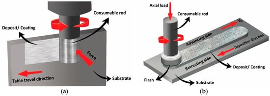
Figure 1.
Friction surfacing deposition: (a) from the side of the tool, (b) from the end of the tool.
2. Materials and Methods
In this research, basic principles of lateral friction surfacing were established, with emphasis on the influence of different process parameters such as axial force, rotation and travel speeds, and material deposition rate on the friction deposition. The major difference in this study is that material transfer occurred from the radial surface of the consumable rod. Furthermore, there is no advancing and retreating side in this novel technique of friction surfacing, therefore, this method provides a more consistent and uniform coating compared to the conventional methods. The influences of process parameters on deposition thickness, coating coverage, process temperature, material consumption rate, and surface roughness of deposited coatings were investigated.
2.1. Experimental Setup of Friction Surfacing Process
In this study, the friction deposition process was performed using a customized JET JMD-18 milling machine, as shown in Figure 2. Moreover, to improve the accuracy of the experimental testing results and provide a more precise and uniform longitudinal movement of the table, the manual feed handle attached to the table was removed, and the machine was equipped with a servo power feed. The transverse table movement of the JET JMD-18 milling machine was controlled manually. Real-time force measurement was made during the friction deposition process using a Kistler 9272 drilling dynamometer, data acquisition apparatus, and LabVIEW programming, as shown in Figure 2.
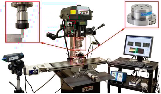
Figure 2.
The experimental setup in this study including benchtop milling machine, dynamometer, and data acquisition apparatus.
2.2. Materials and Experimental Parameters
The length and diameter of the AA60603 consumable rod employed in this investigation were 10 and 1.27 cm, respectively. The AA6063 was selected as the consumable material. This is a medium-strength aluminum alloy that is well suited for friction surfacing. The chemical composition of AA6063 is presented in Table 1.

Table 1.
Chemical composition of AA6063 aluminum alloy.
In this investigation, AISI 1018 low-carbon steel was used as the substrate for deposition with dimensions of 127 mm × 63.5 mm and a thickness of 3.175 mm. This material offers a good balance of mechanical properties such as strength, toughness, and ductility. AISI 1018 has been utilized for various industrial applications and is appropriate for various processes such as welding, machining, drilling, forging, heat treating, and cold drawing. The chemical composition of AISI 1018 is presented in Table 2.
Table 2.
Chemical composition of AISI 1018.
In this study, the friction depositions of the aluminum rod onto the carbon steel were created using two different spindle speeds of 2300 and 3000 rpm, and with constant table traverse speed of 76.2 mm/min. Two different normal forces of 150 and 250 N were tested. Friction surfacing experiments were carried out with single- and dual-pass deposition methods. The purpose of choosing this procedure and these process parameters was to establish the design parameters that have a significant impact on the deposition quality. Selecting these parameters provides an opportunity to investigate the effects of process factors such as applied force, tool rotational speed, and multi-pass deposition on the process temperature, surface roughness, material consumption, deposition thickness, and material characterization. The range of critical process parameters has been selected based on the capability of the machine, as well as the previous experiences in creating deposition. Table 3 represents the details of the process parameters employed in this study.
Table 3.
Process parameters of the experiments.
2.3. Process Temperature Measurement Procedure
All the heat is generated by frictional heating in this technique. In order to record the temperature at the interface of the consumable rod and substrate, an IR FLIR SC655 camera (FLIR Systems, Wilsonville, OR, USA) was used. This camera provides the real-time temperature measurement at any point in the frame, as well as the maximum temperature during the entire friction surfacing process. In order to study the effects of the process parameters on the maximum temperature of the process, the experiments were carried out using tool rotation speeds of 2300 and 3000 rpm and applied forces of 150 and 250 N.
2.4. Surface Roughness Measurement Procedure
In coating quality, the roughness test is one of the most important surface analyses in examining superficial properties. In this investigation, a Landtek SRT6200S surface roughness tester (Guangzhou Landtek Instruments, Guangzhou, China) was used to measure the surface roughness values of the experimental depositions. The resolution of this device is 0.001 μm if measuring roughness values smaller than 10 μm. In order to examine and compare the surface roughness of the samples, 20 different random spots on the deposition surfaces were selected and examined, and the average roughness values of these points were recorded.
2.5. Measurement of Coating Thickness and Material Transfer
The coating thickness and material consumption rate were also measured. By evaluating the volume of rod material consumed in the process, the material consumption rate was determined for the experimental tests. A higher material consumption rate results in thicker deposits. The Leica DM2700 optical microscope (Leica Microsystems, Wetzlar, Germany) was utilized to evaluate the cross-sectional view and thickness of the deposits. In order to prepare the experimental samples for this evaluation, 1 cm of the coated samples was cut and mounted in epoxy, as presented in Figure 3, and then polished using 1 and 0.3 µm alpha-alumina abrasive particles, before viewing on the optical microscope.
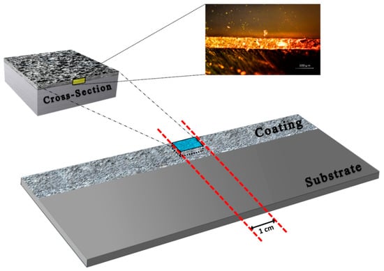
Figure 3.
Cross-sectioning of the coated substrate.
3. Results and Discussion
3.1. Forces and Temperature During the Process
In this study, the friction deposition of the 6063 aluminum alloy consumable tool was made on AISI 1018 carbon steel plate as substrate. The friction surfacing process was performed using manually controlled forces of 150 and 250 N, as presented in Figure 4. The normal force and the tangential force are represented by Fn and Ft, respectively. The rotating consumable rod was forced in contact with the substrate for about a 50 s dwell period to achieve a higher temperature. This process is required to create initial deposition, before moving across the surface of the substrate.
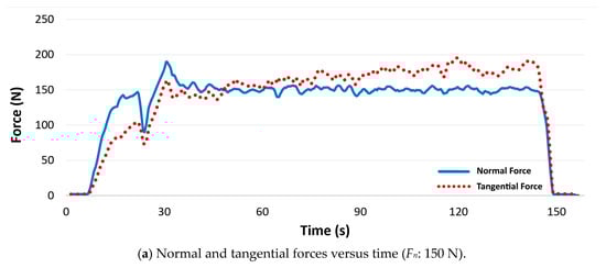
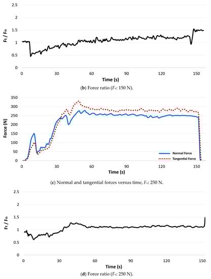
Figure 4.
Manual controlling of the applied forces: (a,c) Normal and tangential forces versus time; (b,d) force ratio (Ft/Fn).
Figure 5 presents a thermal infrared photo of the friction surfacing process using the side of the consumable tool, which shows that the highest temperature occurs at the tool–substrate contact interface.
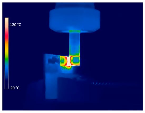
Figure 5.
Thermal infrared photo of friction deposition process using side of the consumable tool.
The maximum temperature profiles of the experiments are presented in Figure 6. The recorded values indicate that the process temperature converges to a steady state in all the experiments. Comparing all the temperature graphs reveals important information about the influence of process parameters. These graphs indicate that the applied force and the tool rotational speed have a significant effect on the process temperature. The temperature at the interface of the consumable tool and substrate rise and converge to its highest temperature in a steady state. By increasing the applied force from 150 to 250 N, the maximum temperature was raised from 230 to 373 °C, and from 296 to 392 °C, as the tool rotational speeds of 2300 and 3000 rpm were used, respectively.
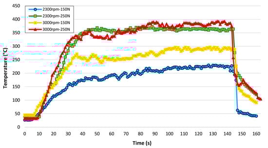
Figure 6.
The maximum temperature during the friction surfacing process.
The temperature measurement shows that the pressing force and tool rotational speed could be employed as temperature controlling factors since they significantly impact on the heat generation process during the friction surfacing. Moreover, the experimental results show that friction surfaced deposition could be carried out using this novel technique at a lower temperature compared to the conventional method of friction surfacing [2]. Figure 7 presents the maximum temperature recorded in this technique. It is shown that the friction surfaced deposition could be fabricated at a maximum temperature as low as 230 °C, which is significantly lower than 326 and 468 °C as the lowest temperatures achieved in the conventional friction surfacing process of 6063 aluminum alloy onto stainless steel [47] and carbon steel [48], respectively. Applying lower forces and tool rotational speeds may decrease the maximum process temperature even more in this technique.
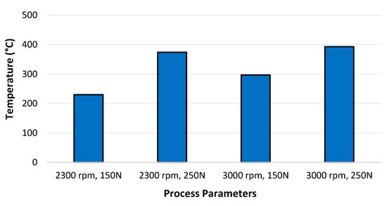
Figure 7.
Maximum temperature in the friction surfacing process.
3.2. Influence of Process Parameters on the Surface Roughness
The fabrication of 6063 aluminum alloy from the side of the consumable tool onto carbon steel under different sets of process parameters is presented in Figure 8. As presented in Table 3, the experiments were carried out in two approaches of single- and double-pass deposition using two different applied forces of 150 and 250 N, and two different tool rotational speeds of 2300 and 3000 rpm. The aluminum coating is the white layer located in the top half of each sample’s photo. The initial visual assessment indicates that this technique is capable of providing an ultra-thin coating with a great level of coverage. The first layer of friction depositions exhibits good coverage, however, adding the second layer of deposition further improves the coating coverage slightly. Moreover, the visual assessment indicates that using higher values of pressing force creates a rougher coating.
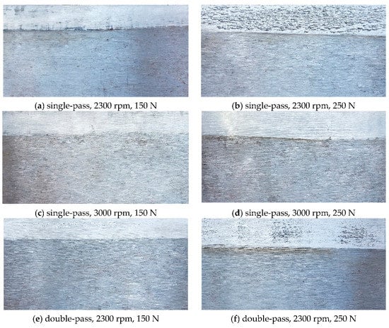
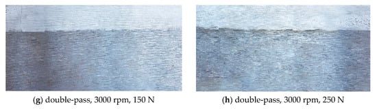
Figure 8.
Experimental samples using different process parameters.
The surface roughness values of depositions and the influence of process parameters, such as the applied force, tool rotational speed, and number of passes of deposition, on the surface roughness values are examined. The surface roughness, Ra, refers to the arithmetical mean deviation of the assessed surface profile. The surface roughness measurement shows that friction surfacing deposition from the side of the consumable tool can provide coatings with roughness values in the order of 1 micrometer.
Figure 9 presents the influence of different process parameters on the surface roughness of depositions in the novel friction surfacing technique. As is shown in Figure 8, the visual assessment showed that applying a higher pressing force during the novel technique of friction surfacing provides a rougher surface. As the roughness measurement shows, the surface roughness was increased as the pressing force was raised from 150 to 250 N, in both single- and two-pass coatings. Furthermore, the results of the measurements reveal that tool rotational speed plays an important role in friction surfacing. This evaluation shows that increasing the tool rotational speed from 2300 to 3000 rpm mostly results in lower coating surface roughness values which means smoother deposition.
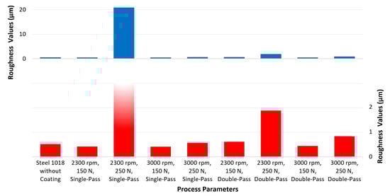
Figure 9.
Influence of process parameters on the surface roughness (Ra) of the coatings.
Multi-layer friction deposition is possible through the novel friction surfacing technique. Increasing the number of coating layers may change the physical properties and characteristics of the metallic deposition. The experimental result shows that adding the second layer of coating slightly improves the coating coverage; however, its influence on the surface roughness varies. Figure 9 shows that adding the second layer of deposition has different impacts on the final surface roughness values of coatings fabricated using various combinations of process parameters. The result of the measurements shows that creating ultra-smooth coatings using multiple deposition layers is possible through the novel friction surfacing technique.
3.3. Further Investigation on the Samples with High Surface Roughness Values
The evaluation of surface roughness values of the coated surfaces reveals that the novel friction surfacing technique has the capability of creating ultra-smooth surfaces with roughness values in the order of 1 micrometer. However, the roughness values of sample #2 provided by the applied force of 250 N and the tool rotational speed of 2300 rpm is high compared to the other samples. The high roughness value of this sample led us to do more investigation on experiments in which their process parameters have values close to values associated with sample #2. In order to further study the roughest sample, a set of experiments were designed with attention to the limitations of the machines and instruments. The highlighted process parameters’ values in Table 4 present the further sets of experiments that were performed.
Table 4.
Additional experiments to study the roughest surface.
Focusing more on the roughest sample resulted in the coatings which are rougher than other samples, Figure 10 presents the roughness values of coated layers created by process factors presented in Table 4. As is demonstrated in Figure 10, it can be concluded that the process parameters close to 2300 rpm and 250 N provide rougher surfaces. This fact indicates that the very high roughness value recorded in sample #2 is not an outlier value, and it has a root in the process temperature and material transfer process associated with it.
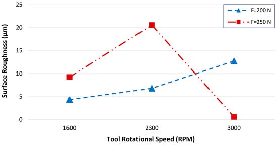
Figure 10.
The surface roughness (Ra) values of experimental samples provided by process parameters close to the roughest sample.
3.4. Influence of Process Parameters and Number of Coating Layers on Material Consumption
Friction surfacing using the side of the consumable tool is a great alternative technique to create super-thin coating layers in which the material consumption rate is very low. Figure 11a provides detailed information about the volume of tool material consumed per millimeter of coating width fabricated on the steel substrate during this process. It is seen that using higher applied force resulted in a significant increment in material consumption; however, increasing the tool rotational speed decreases the tool material consumption in single-pass deposition. Figure 11b reveals that by adding the second layer of deposition, a reverse material transfer process occurs, which means a portion of material from the first fabricated layer of the coating is transferred back to the rod. Therefore, by using even less material, better coverage was obtained through a dual-pass deposition process.
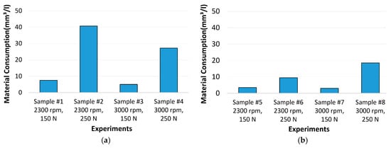
Figure 11.
Tool material consumption through single- and dual-pass deposition processes: (a) single-pass coating; (b) dual-pass coating.
3.5. Influence of Process Parameters on Coating Thickness
The geometry of depositions was investigated by cross-sectional views of the deposition layers using a Leica DM2700 optical microscope (Leica Microsystems, Wetzlar, Germany). As was presented in Figure 3, 1 cm of the coated substrates was cut and mounted in epoxy. In the next stage, they were polished using 1 and 0.3 µm alpha-alumina abrasive particles, respectively, before viewing on the optical microscope. Figure 12 presents the cross-sectional viewing of the experimental samples. The highest thickness value was recorded in some areas on sample #2 (2300 rpm, 250 N), and it was around 200 µm. All other sample cross-sectional images exhibit an average layer thickness that was between 16 to 70 µm, as presented in Figure 13. The thickness values of the depositions emphasize that by adding the second pass of deposition, a reverse material transfer process occurs. Therefore, a portion of deposited material from the first fabricated layer of the coating was transferred back to the rod which resulted in lower thickness values in the double-pass depositions.
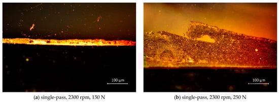
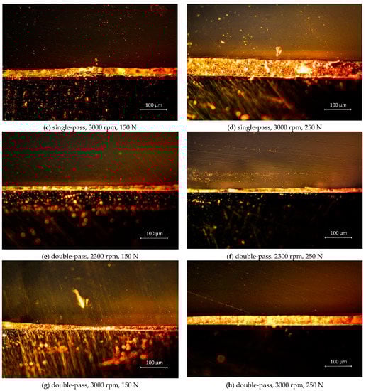
Figure 12.
Optical microscope view of cross-sections of depositions using 20× magnification of a Leica DM2700.
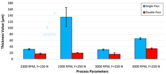
Figure 13.
The thickness of coating layers created in single- and double-pass deposition processes.
4. Summary and Conclusions
In this investigation, different combinations of process parameters such as tool rotational speeds of 2300 and 3000 rpm, applied forces of 150 and 250 N, and single- and dual-pass deposition approaches were deployed, and 6063 aluminum deposition was successfully fabricated onto AISI 1018 carbon steel from the side of the consumable tool. In this investigation, real-time force measurement, surface roughness evaluation, process temperature analysis, and cross-sectional viewing geometry using optical microscopy were conducted. The following conclusions were drawn.
- The lateral friction surfacing technique using the side of the consumable tool creates no flash and can save a significant amount of the tool material and increase the economic efficiency. As was discussed previously, in the conventional friction surfacing process using the end of the tool, flash formation is a serious issue which can waste up to 60 percent of the consumable tool material.
- The deposition thickness and material consumption were found to be dependent on the rotational speed, pressing force, and the number of coating passes. The result of the experiments shows that a dual-pass deposition had complete coverage and lower coating thicknesses compared to the single-pass deposition.
- The surface roughness was found to be the lowest for process parameters of 2300 and 3000 rpm, 150 N and single-pass mode, which was 0.45 µm. The experiments show that this technique is capable of producing coating layers with roughness values of less than 1 µm. Increasing the applied force increased the roughness values, however, in most of experiments, increasing the tool rotational speed results in lower roughness values.
- A spike in surface roughness was found at process parameters of 2300 rpm, 250 N, and single-pass mode. Further experimental investigation of surface roughness for similar process parameters resulted in high surface roughness values, and it was found that the high roughness value recorded at process parameters of 2300 rpm and 250 N did not occur accidentally, and it had a root in the process temperature and material transfer process associated with it.
- Friction deposition could be carried out using the novel technique of friction surfacing at a very lower temperature compared to the conventional method of this method. The maximum temperature recorded was as low as 230 °C at the interface between the tool and workpiece, while a high forging force of 150 N and tool rotational speed of 2300 rpm were employed. This fact indicates that the novel method of friction surfacing provides the ability to create friction deposition at a low temperature which reduces thermal effect on grain structure and metallurgical properties.
Author Contributions
E.S.: Conceptualization, Formal analysis, Investigation, Methodology, Data curation, Visualization, Writing—Original draft preparation, Writing—review and editing. S.F.M.: Supervision, Methodology, Funding acquisition, Resources, Writing—Reviewing and editing. All authors have read and agreed to the published version of the manuscript.
Funding
This research is supported by General Motors and NSF CMMI grant # 1763147.
Acknowledgments
We thank Farnaz Kaviari (University of Hawaii at Manoa) for her graphical support in preparing some of the figures.
Conflicts of Interest
The authors declare no conflict of interest.
References
- Klopstock, H.; Neelands, A.R. An Improved Method of Joining or Welding Metals. GB Patent Application No 572789, 17 October 1941. [Google Scholar]
- Seidi, E.; Miller, S.F. Friction surfacing using consumable tools: A review. In Processes and Materials, Proceedings of the ASME 2019 14th International Manufacturing Science and Engineering Conference, Erie, PA, USA, 10–14 July 2019; ASME: New York, NY, USA, 2019; Volume 2, p. V002T03A048. [Google Scholar]
- Huang, Y.; Lv, Z.; Wan, L.; Shen, J.; Dos Santos, J.F. A new method of hybrid friction stir welding assisted by friction surfacing for joining dissimilar Ti/Al alloy. Mater. Lett. 2017, 207, 172–175. [Google Scholar] [CrossRef]
- Badheka, K.; Badheka, V. Friction surfacing of aluminium on steel: An experimental approach. Mater. Today Proc. 2017, 4, 9937–9941. [Google Scholar] [CrossRef]
- Rao, K.P.; Damodaram, R.; Rafi, H.K.; Ram, G.D.J.; Reddy, G.M.; Nagalakshmi, R. Friction surfaced Stellite6 coatings. Mater. Charact. 2012, 70, 111–116. [Google Scholar] [CrossRef]
- Jujare, T.; Kumar, A.; Kailas, S.V.; Bhat, K.U. Friction surfacing of mild steel by copper: A feasibility study. Procedia Mater. Sci. 2014, 5, 1300–1307. [Google Scholar] [CrossRef]
- De Macedo, M.L.K.; Pinheiro, G.A.; Dos Santos, J.F.; Strohaecker, T.R. Deposit by friction surfacing and its applications. Weld. Int. 2010, 24, 422–431. [Google Scholar] [CrossRef]
- Liu, X.-M.; Zou, Z.; Zhang, Y.; Qu, S.; Wang, X. Transferring mechanism of the coating rod in friction surfacing. Surf. Coat. Technol. 2008, 202, 1889–1894. [Google Scholar] [CrossRef]
- Gandra, J.; Miranda, R.M.; Vilaça, P. Performance analysis of friction surfacing. J. Mater. Process. Technol. 2012, 212, 1676–1686. [Google Scholar] [CrossRef]
- Chandrasekaran, M.; Batchelor, A.W.; Jana, S. Friction surfacing of metal coatings on steel and aluminum substrate. J. Mater. Process. Technol. 1997, 72, 446–452. [Google Scholar] [CrossRef]
- Guo, D.; Kwok, C.; Chan, S. Strengthened forced convection—A novel method for improving the pitting corrosion resistance of friction-surfaced stainless steel coating. Mater. Des. 2019, 182, 108037. [Google Scholar] [CrossRef]
- Guo, D.; Kwok, C.T.; Chan, S. Spindle speed in friction surfacing of 316L stainless steel—How it affects the microstructure, hardness and pitting corrosion resistance. Surf. Coat. Technol. 2019, 361, 324–341. [Google Scholar] [CrossRef]
- Da Silva, M.M.; Afonso, M.L.B.; Silva, S.L.N.; Troysi, F.C.T.D.; Dos Santos, Í.B.; Brito, P. Application of the friction surfacing process in a CNC machining center: A viability assessment for producing Al-alloy coatings on low carbon steel. J. Braz. Soc. Mech. Sci. Eng. 2018, 40, 14. [Google Scholar] [CrossRef]
- Miles, M.; Kohkonen, K.; Packer, S.; Steel, R.; Siemssen, B.; Sato, Y.S. Solid state spot joining of sheet materials using consumable bit. Sci. Technol. Weld. Join. 2009, 14, 72–77. [Google Scholar] [CrossRef]
- Sahoo, D.K.; Chari, A.N.; Reddy, A.S. Optimization & characterization of friction surfaced coatings of AA6063 aluminium alloy over AISI316 stainless steel substrate. Mater. Today Proc. 2020, 23, 565–572. [Google Scholar]
- Sudherson, D.P.S.; Anandkumar, P.P.; Jinu, G.; Balasubramanian, K.A.; Vettivel, S.C. Experimental investigation on corrosion behavior of friction surfaced mild steel with aluminum alloy 5083-Cadmium composite. Mater. Res. Express 2019, 6, 086587. [Google Scholar] [CrossRef]
- Rao, K.P.; Sreenu, A.V.; Rafi, H.K.; Libin, M.; Balasubramaniam, K. Tool steel and copper coatings by friction surfacing—A thermography study. J. Mater. Process. Technol. 2012, 212, 402–407. [Google Scholar] [CrossRef]
- Stegmueller, M.; Grant, R.J.; Schindele, P. Quantification of the interfacial roughness when coating stainless steel onto aluminium by friction surfacing. Surf. Coat. Technol. 2019, 375, 22–33. [Google Scholar] [CrossRef]
- Zhang, G.F.; Jiao, W.M.; Zhang, J.X. Filling friction stir weld keyhole using pin free tool and T shaped filler bit. Sci. Technol. Weld. Join. 2013, 19, 98–104. [Google Scholar] [CrossRef]
- Casalino, G.; Campanelli, S.; Mortello, M. Influence of shoulder geometry and coating of the tool on the friction stir welding of aluminium alloy plates. Procedia Eng. 2014, 69, 1541–1548. [Google Scholar] [CrossRef]
- Stegmueller, M.; Schindele, P.; Grant, R.J. Inductive heating effects on friction surfacing of stainless steel onto an aluminium substrate. J. Mater. Process. Technol. 2015, 216, 430–439. [Google Scholar] [CrossRef][Green Version]
- Stegmüller, M.J.; Grant, R.J.; Schindele, P. Improvements in the process efficiency and bond strength when friction surfacing stainless steel onto aluminium substrates. Proc. Inst. Mech. Eng. Part L J. Mater. Des. Appl. 2017, 233, 687–698. [Google Scholar] [CrossRef]
- Kumar, B.V.; Reddy, G.M.; Mohandas, T. Influence of process parameters on physical dimensions of AA6063 aluminium alloy coating on mild steel in friction surfacing. Def. Technol. 2015, 11, 275–281. [Google Scholar] [CrossRef]
- Nixon, R.G.S.; Mohanty, B.S.; Bhaskar, G.B. Effect of process parameters on physical measurements of AISI316 stainless steel coating on EN24 in friction surfacing. Mater. Manuf. Process. 2017, 33, 778–785. [Google Scholar] [CrossRef]
- Kumar, V.A.; Sammaiah, P. Comparison of process parameters influence on mechanical and metallurgical properties of zinc coating on mild steel & aluminium during mechanical process. Mater. Today Proc. 2018, 5, 3861–3866. [Google Scholar] [CrossRef]
- Li, H.; Qin, W.; Galloway, A.M.; Toumpis, A. Friction surfacing of aluminium alloy 5083 on DH36 steel plate. Metals 2019, 9, 479. [Google Scholar] [CrossRef]
- Sahoo, D.K.; Mohanty, B.S. Evaluation of bond strength on deposition of aluminium 6063 alloy over EN24 medium carbon steel by friction surfacing using different mechtrode diameter. e-J. Surf. Sci. Nanotechnol. 2019, 17, 83–94. [Google Scholar] [CrossRef]
- Batchelor, A.; Jana, S.; Koh, C.; Tan, C. The effect of metal type and multi-layering on friction surfacing. J. Mater. Process. Technol. 1996, 57, 172–181. [Google Scholar] [CrossRef]
- Govardhan, D.; Kumar, A.; Murti, K.; Reddy, G.M. Characterization of austenitic stainless steel friction surfaced deposit over low carbon steel. Mater. Des. 2012, 36, 206–214. [Google Scholar] [CrossRef]
- Govardhan, D.; Sammaiah, K.; Murti, K.; Reddy, G.M. Evaluation of bond quality for stainless steel-carbon steel friction surfaced deposits. Mater. Today Proc. 2015, 2, 3511–3519. [Google Scholar] [CrossRef]
- Gandra, J.; Pereira, D.; Miranda, R.M.; Vilaça, P. Influence of process parameters in the friction surfacing of AA 6082-T6 over AA 2024-T3. Procedia CIRP 2013, 7, 341–346. [Google Scholar] [CrossRef]
- Shinoda, T.; Li, J.Q.; Katoh, Y.; Yashiro, T. Effect of process parameters during friction coating on properties of non-dilution coating layers. Surf. Eng. 1998, 14, 211–216. [Google Scholar] [CrossRef]
- Rafi, H.K.; Ram, G.D.J.; Phanikumar, G.; Rao, K.P. Friction surfaced tool steel (H13) coatings on low carbon steel: A study on the effects of process parameters on coating characteristics and integrity. Surf. Coat. Technol. 2010, 205, 232–242. [Google Scholar] [CrossRef]
- Vitanov, V.; Voutchkov, I. Process parameters selection for friction surfacing applications using intelligent decision support. J. Mater. Process. Technol. 2005, 159, 27–32. [Google Scholar] [CrossRef]
- Galvis, J.; Oliveira, P.; Hupalo, M.; Martins, J.; Carvalho, A. Influence of friction surfacing process parameters to deposit AA6351-T6 over AA5052-H32 using conventional milling machine. J. Mater. Process. Technol. 2017, 245, 91–105. [Google Scholar] [CrossRef]
- Kumar, B.V.; Reddy, G.M.; Mohandas, T. Identification of suitable process parameters for friction surfacing of mild steel with AA6063 aluminium alloy. Int. J. Adv. Manuf. Technol. 2014, 74, 433–443. [Google Scholar] [CrossRef]
- Fitseva, V.; Hanke, S.; Dos Santos, J.; Stemmer, P.; Gleising, B. The role of process temperature and rotational speed in the microstructure evolution of Ti-6Al-4V friction surfacing coatings. Mater. Des. 2016, 110, 112–123. [Google Scholar] [CrossRef]
- Murugan, C.K.; Balusamy, V.; Padmanaban, R.; Vignesh, R.V. Friction surfacing mild-steel with Monel and predicting the coating parameters using fuzzy logic. Mater. Today Proc. 2018, 5, 16402–16410. [Google Scholar] [CrossRef]
- Rathee, S.; Maheshwari, S.; Siddiquee, A.N. Issues and strategies in composite fabrication via friction stir processing: A review. Mater. Manuf. Process. 2017, 33, 239–261. [Google Scholar] [CrossRef]
- Bararpour, S.M.; Aval, H.J.; Jamaati, R. Modeling and experimental investigation on friction surfacing of aluminum alloys. J. Alloy. Compd. 2019, 805, 57–68. [Google Scholar] [CrossRef]
- Rahmati, Z.; Aval, H.J.; Nourouzi, S.; Jamaati, R. Modeling and experimental study of friction surfacing of AA2024 alloy over AA1050 plates. Mater. Res. Express 2019, 6, 0865g2. [Google Scholar] [CrossRef]
- Huang, Y.X.; Han, B.; Tian, Y.; Liu, H.J.; Lv, S.X.; Feng, J.C.; Leng, J.S.; Li, Y. New technique of filling friction stir welding. Sci. Technol. Weld. Join. 2011, 16, 497–501. [Google Scholar] [CrossRef]
- Huang, Y.; Han, B.; Lv, S.X.; Feng, J.C.; Liu, H.J.; Leng, J.S.; Li, Y. Interface behaviours and mechanical properties of filling friction stir weld joining AA 2219. Sci. Technol. Weld. Join. 2012, 17, 225–230. [Google Scholar] [CrossRef]
- Han, B.; Huang, Y.; Lv, S.; Wan, L.; Feng, J.; Fu, G. AA7075 bit for repairing AA2219 keyhole by filling friction stir welding. Mater. Des. 2013, 51, 25–33. [Google Scholar] [CrossRef]
- Rafi, H.K.; Ram, G.J.; Phanikumar, G.; Rao, K.P. Microstructural evolution during friction surfacing of tool steel H13. Mater. Des. 2011, 32, 82–87. [Google Scholar] [CrossRef]
- Sekharbabu, R.; Rafi, H.K.; Rao, K.P. Characterization of D2 tool steel friction surfaced coatings over low carbon steel. Mater. Des. 2013, 50, 543–550. [Google Scholar] [CrossRef]
- Sahoo, D.K.; Mohanty, B.S.; Pradeep, A.M.; John, A.D.F. An experimental study on friction surfaced coating of Aluminium 6063 over AISI 316 stainless steel substrate. Mater. Today Proc. 2020. [Google Scholar] [CrossRef]
- Sahoo, D.; Mohanty, B.; Veetil, A.M. Evaluation of Bond Strength and Flash Mass on Friction Surfaced Deposition of Aluminium 6063 over IS 2062 Low Carbon Steel Using Different Mechtrode Face. Ann. Chim. Sci. Matériaux 2020, 44, 109–119. [Google Scholar] [CrossRef]
Publisher’s Note: MDPI stays neutral with regard to jurisdictional claims in published maps and institutional affiliations. |
© 2020 by the authors. Licensee MDPI, Basel, Switzerland. This article is an open access article distributed under the terms and conditions of the Creative Commons Attribution (CC BY) license (http://creativecommons.org/licenses/by/4.0/).